EP0925548B1 - Verfahren zum übertragen von daten in einem radiofrequenz identifikations-system - Google Patents
Verfahren zum übertragen von daten in einem radiofrequenz identifikations-system Download PDFInfo
- Publication number
- EP0925548B1 EP0925548B1 EP97944877A EP97944877A EP0925548B1 EP 0925548 B1 EP0925548 B1 EP 0925548B1 EP 97944877 A EP97944877 A EP 97944877A EP 97944877 A EP97944877 A EP 97944877A EP 0925548 B1 EP0925548 B1 EP 0925548B1
- Authority
- EP
- European Patent Office
- Prior art keywords
- sent
- signal
- reader
- answer signal
- transponder
- Prior art date
- Legal status (The legal status is an assumption and is not a legal conclusion. Google has not performed a legal analysis and makes no representation as to the accuracy of the status listed.)
- Expired - Lifetime
Links
Images

Classifications
-
- G—PHYSICS
- G07—CHECKING-DEVICES
- G07F—COIN-FREED OR LIKE APPARATUS
- G07F7/00—Mechanisms actuated by objects other than coins to free or to actuate vending, hiring, coin or paper currency dispensing or refunding apparatus
- G07F7/08—Mechanisms actuated by objects other than coins to free or to actuate vending, hiring, coin or paper currency dispensing or refunding apparatus by coded identity card or credit card or other personal identification means
- G07F7/10—Mechanisms actuated by objects other than coins to free or to actuate vending, hiring, coin or paper currency dispensing or refunding apparatus by coded identity card or credit card or other personal identification means together with a coded signal, e.g. in the form of personal identification information, like personal identification number [PIN] or biometric data
- G07F7/1008—Active credit-cards provided with means to personalise their use, e.g. with PIN-introduction/comparison system
-
- G—PHYSICS
- G06—COMPUTING; CALCULATING OR COUNTING
- G06K—GRAPHICAL DATA READING; PRESENTATION OF DATA; RECORD CARRIERS; HANDLING RECORD CARRIERS
- G06K19/00—Record carriers for use with machines and with at least a part designed to carry digital markings
- G06K19/06—Record carriers for use with machines and with at least a part designed to carry digital markings characterised by the kind of the digital marking, e.g. shape, nature, code
- G06K19/067—Record carriers with conductive marks, printed circuits or semiconductor circuit elements, e.g. credit or identity cards also with resonating or responding marks without active components
- G06K19/07—Record carriers with conductive marks, printed circuits or semiconductor circuit elements, e.g. credit or identity cards also with resonating or responding marks without active components with integrated circuit chips
- G06K19/0723—Record carriers with conductive marks, printed circuits or semiconductor circuit elements, e.g. credit or identity cards also with resonating or responding marks without active components with integrated circuit chips the record carrier comprising an arrangement for non-contact communication, e.g. wireless communication circuits on transponder cards, non-contact smart cards or RFIDs
- G06K19/0726—Record carriers with conductive marks, printed circuits or semiconductor circuit elements, e.g. credit or identity cards also with resonating or responding marks without active components with integrated circuit chips the record carrier comprising an arrangement for non-contact communication, e.g. wireless communication circuits on transponder cards, non-contact smart cards or RFIDs the arrangement including a circuit for tuning the resonance frequency of an antenna on the record carrier
-
- G—PHYSICS
- G06—COMPUTING; CALCULATING OR COUNTING
- G06K—GRAPHICAL DATA READING; PRESENTATION OF DATA; RECORD CARRIERS; HANDLING RECORD CARRIERS
- G06K7/00—Methods or arrangements for sensing record carriers, e.g. for reading patterns
- G06K7/0008—General problems related to the reading of electronic memory record carriers, independent of its reading method, e.g. power transfer
-
- G—PHYSICS
- G06—COMPUTING; CALCULATING OR COUNTING
- G06Q—INFORMATION AND COMMUNICATION TECHNOLOGY [ICT] SPECIALLY ADAPTED FOR ADMINISTRATIVE, COMMERCIAL, FINANCIAL, MANAGERIAL OR SUPERVISORY PURPOSES; SYSTEMS OR METHODS SPECIALLY ADAPTED FOR ADMINISTRATIVE, COMMERCIAL, FINANCIAL, MANAGERIAL OR SUPERVISORY PURPOSES, NOT OTHERWISE PROVIDED FOR
- G06Q20/00—Payment architectures, schemes or protocols
- G06Q20/30—Payment architectures, schemes or protocols characterised by the use of specific devices or networks
- G06Q20/34—Payment architectures, schemes or protocols characterised by the use of specific devices or networks using cards, e.g. integrated circuit [IC] cards or magnetic cards
- G06Q20/341—Active cards, i.e. cards including their own processing means, e.g. including an IC or chip
-
- G—PHYSICS
- G06—COMPUTING; CALCULATING OR COUNTING
- G06Q—INFORMATION AND COMMUNICATION TECHNOLOGY [ICT] SPECIALLY ADAPTED FOR ADMINISTRATIVE, COMMERCIAL, FINANCIAL, MANAGERIAL OR SUPERVISORY PURPOSES; SYSTEMS OR METHODS SPECIALLY ADAPTED FOR ADMINISTRATIVE, COMMERCIAL, FINANCIAL, MANAGERIAL OR SUPERVISORY PURPOSES, NOT OTHERWISE PROVIDED FOR
- G06Q20/00—Payment architectures, schemes or protocols
- G06Q20/38—Payment protocols; Details thereof
- G06Q20/40—Authorisation, e.g. identification of payer or payee, verification of customer or shop credentials; Review and approval of payers, e.g. check credit lines or negative lists
- G06Q20/409—Device specific authentication in transaction processing
- G06Q20/4097—Device specific authentication in transaction processing using mutual authentication between devices and transaction partners
- G06Q20/40975—Device specific authentication in transaction processing using mutual authentication between devices and transaction partners using encryption therefor
-
- G—PHYSICS
- G11—INFORMATION STORAGE
- G11C—STATIC STORES
- G11C11/00—Digital stores characterised by the use of particular electric or magnetic storage elements; Storage elements therefor
- G11C11/21—Digital stores characterised by the use of particular electric or magnetic storage elements; Storage elements therefor using electric elements
- G11C11/34—Digital stores characterised by the use of particular electric or magnetic storage elements; Storage elements therefor using electric elements using semiconductor devices
- G11C11/40—Digital stores characterised by the use of particular electric or magnetic storage elements; Storage elements therefor using electric elements using semiconductor devices using transistors
- G11C11/41—Digital stores characterised by the use of particular electric or magnetic storage elements; Storage elements therefor using electric elements using semiconductor devices using transistors forming static cells with positive feedback, i.e. cells not needing refreshing or charge regeneration, e.g. bistable multivibrator or Schmitt trigger
- G11C11/413—Auxiliary circuits, e.g. for addressing, decoding, driving, writing, sensing, timing or power reduction
- G11C11/417—Auxiliary circuits, e.g. for addressing, decoding, driving, writing, sensing, timing or power reduction for memory cells of the field-effect type
- G11C11/419—Read-write [R-W] circuits
-
- G—PHYSICS
- G11—INFORMATION STORAGE
- G11C—STATIC STORES
- G11C7/00—Arrangements for writing information into, or reading information out from, a digital store
- G11C7/10—Input/output [I/O] data interface arrangements, e.g. I/O data control circuits, I/O data buffers
- G11C7/1048—Data bus control circuits, e.g. precharging, presetting, equalising
-
- G—PHYSICS
- G11—INFORMATION STORAGE
- G11C—STATIC STORES
- G11C7/00—Arrangements for writing information into, or reading information out from, a digital store
- G11C7/10—Input/output [I/O] data interface arrangements, e.g. I/O data control circuits, I/O data buffers
- G11C7/1051—Data output circuits, e.g. read-out amplifiers, data output buffers, data output registers, data output level conversion circuits
Definitions
- the invention relates to a method for transmitting data in one Radio frequency identification system from one transponder to one Reading device by load modulation of one emitted by the reading device Interrogation signal
- An RFID transponder generally consists of an antenna coil and an integrated circuit that contains all the necessary electronic Circuit blocks, such as B. for power supply, clock generation, for sequence control and for storing the for identification necessary data.
- B. for power supply
- clock generation for sequence control
- storing for identification necessary data.
- the one connected in parallel to the antenna coil Capacity is also often part of the integrated circuit. she can, however, also be formed by a discrete component.
- the RFID reader consists of an oscillating circuit with a transmitter coil and a capacitance that is provided by a driver stage with a signal with a generally fixed frequency (e.g. 125 kHz) is driven.
- a driver stage with a signal with a generally fixed frequency (e.g. 125 kHz) is driven.
- the reader contains electronic circuit blocks to be read by the Detect absorption modulation data sent by the transponder and around data and commands, e.g. B. by modulating the field to the Send transponder.
- the reader and transponder form the data and the Energy transfer a loosely coupled transformer. That is why Energy transfer relatively low.
- the object of the invention is therefore to provide a method for transmitting Data in a radio frequency identification system from one Transponders to a reader by modulating a load from the Specify reader signal sent by a single data transmission provides the correct result.
- the transponder at the beginning of the reception of the interrogation signal is initialized and responds by sending the response signal initially a predetermined number of not to the response signal belonging data bits and then in recurring sequence a terminator sequence followed by the Response signal until the interrogation signal is interrupted.
- the terminator sequence advantageously consists of a bit sequence which in the actual response signal cannot occur.
- the query signal for a duration of 1.5 Bit periods is unmodulated.
- Such a sequence can actually Response signal does not occur and is therefore safe from the reader recognized. It is also possible to do this when sending the terminator sequence Interrogation signal for load modulation for a period of 1.5 bit periods.
- the time period of 1.5 bit periods is important for reliable detection are reliably recognized by the reader as a terminator sequence.
- the transponder sends at the beginning of the data transmission, such as B. during initialization, some irrelevant data bits, followed by a special, non-data typical Pattern (terminator) consisting, for example, of sequences of 1.5 Bit periods. This will synchronize the reader and in addition, the terminator sequence makes the start of a valid one Data word displayed, so that this already at the first transmission is correctly recognized.
- a special, non-data typical Pattern consisting, for example, of sequences of 1.5 Bit periods.
- the Transponder After this Reception of the query signal generated by the reader, the Transponder, initialized.
- the initialization includes setting the communication parameters and the transfer of the transponder to a defined initial state.
- the transponder then begins by modulating the load of the interrogation signal to the reader send. to give the reader enough time one at a time Generate constant query signal frame that is used for secure Decoding of the data sent from the transponder to the reader is necessary, the transponder first a predetermined Number of data bits not belonging to the response signal sent. During this time the reader will also respond to the response signal synchronized.
- a terminator sequence is then sent, which is thereby distinguishes that it cannot occur in the actual data flow.
- a 3-bit sequence has been found to be particularly advantageous in the case of that the interrogation signal is unmodulated for a period of 1.5 bit periods.
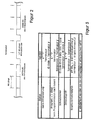
- Figure 2 shows a terminator in data flow. In addition to the property that this sequence cannot occur in the actual data flow they are characterized by the very short duration.
- the response signal becomes the reader Posted. If the reader has recognized the terminator sequence, use with a very high probability the answer signal is immediately correct decoded. Nevertheless, the answer signal is followed by one
- the terminator sequence is repeatedly sent by the transponder until the interrogation signal is interrupted. Then either Communication between the reader and the transponder ended or the reader transmits data or commands to the transponder.
- the data can be correct immediately on the first transfer be recognized. This leads to a shortening of the duration of the Data transmission.
Abstract
Description
- Figur 1
- Ablaufdiagramm des Verfahrens;
- Figur 2
- zeigt einen Terminator in Datenfluß;
- Figur 3
- zeigt eine Tabelle mit den Betriebszuständen, die zum senden des Terminators führen.
Claims (6)
- Verfahren zum Übertragen von Daten in einem Radiofrequenz Identifikations-System von einem Transponder zu einem Lesegerät durch Belastungsmodulation eines vom Lesegerät ausgesendeten Abfragesignals, wobei der Transponder bei Beginn des Empfangs des Abfragesignals initialisiert wird und mit dem Senden des Anwortsignals antwortet,
dadurch gekennzeichnet,
daß zunächst eine vorbestimmte Anzahl von nicht zum Antwortsignal gehörenden Datenbits gesendet werden und
daß anschließend solange in wiederkehrender Folge eine Terminatorsequenz gefolgt von dem Antwortsignal gesendet wird bis das Abfragesignal unterbrochen wird. - Verfahren zum Übertragen von Daten nach Anspruch 1, dadurch gekennzeichnet, daß die Terminatorsequenz aus einer Bitfolge besteht, die im eigentlichen Antwortsignal nicht auftreten kann.
- Verfahren zum Übertragen von Daten nach Anspruch 1 oder 2, dadurch gekennzeichnet, daß beim Senden der Terminatorsequenz das Abfragesignal für eine Dauer von 1,5 Bitperioden nicht moduliert wird.
- Verfahren zum Übertragen von Daten nach Anspruch 1 oder 2, dadurch gekennzeichnet, daß beim Senden der Terminatorsequenz das Abfragesignal für eine Dauer von 1,5 Bitperioden belastungsmoduliert wird.
- Verfahren zum Übertragen von Daten nach einem der Ansprüche 1 - 4,
dadurch gekennzeichnet, daß als vorbestimmte Anzahl von nicht zum Antwortsignal gehörenden Datenbits eine Folge von 3 bis 10 logische Einsen gesendet werden. - Verfahren zum übertragen von Daten nach einem der Ansprüche 1 - 4,
dadurch gekennzeichnet, daß als vorbestimmte Anzahl von nicht zum Antwortsignal gehörenden Datenbits eine Folge von 3 bis 10 logische Nullen gesendet werden.
Applications Claiming Priority (3)
| Application Number | Priority Date | Filing Date | Title |
|---|---|---|---|
| DE19637319 | 1996-09-13 | ||
| DE19637319 | 1996-09-13 | ||
| PCT/EP1997/005010 WO1998011496A1 (de) | 1996-09-13 | 1997-09-13 | Verfahren zum übertragen von daten in einem radiofrequenz identifikations-system |
Publications (2)
| Publication Number | Publication Date |
|---|---|
| EP0925548A1 EP0925548A1 (de) | 1999-06-30 |
| EP0925548B1 true EP0925548B1 (de) | 2001-03-28 |
Family
ID=7805530
Family Applications (3)
| Application Number | Title | Priority Date | Filing Date |
|---|---|---|---|
| EP97942920A Expired - Lifetime EP0925551B1 (de) | 1996-09-13 | 1997-09-13 | Verfahren zum abgleich eines empfangsschwingkreises eines transponders in einem rfid system |
| EP97944877A Expired - Lifetime EP0925548B1 (de) | 1996-09-13 | 1997-09-13 | Verfahren zum übertragen von daten in einem radiofrequenz identifikations-system |
| EP97909259A Expired - Lifetime EP0925665B1 (de) | 1996-09-13 | 1997-09-13 | Verfahren zur kryptologischen authentifizierung in einem radiofrequenz-identifikations-system |
Family Applications Before (1)
| Application Number | Title | Priority Date | Filing Date |
|---|---|---|---|
| EP97942920A Expired - Lifetime EP0925551B1 (de) | 1996-09-13 | 1997-09-13 | Verfahren zum abgleich eines empfangsschwingkreises eines transponders in einem rfid system |
Family Applications After (1)
| Application Number | Title | Priority Date | Filing Date |
|---|---|---|---|
| EP97909259A Expired - Lifetime EP0925665B1 (de) | 1996-09-13 | 1997-09-13 | Verfahren zur kryptologischen authentifizierung in einem radiofrequenz-identifikations-system |
Country Status (7)
| Country | Link |
|---|---|
| US (3) | US6272321B1 (de) |
| EP (3) | EP0925551B1 (de) |
| JP (3) | JP2001501051A (de) |
| AU (4) | AU4702997A (de) |
| DE (3) | DE59707804D1 (de) |
| ES (3) | ES2157089T3 (de) |
| WO (4) | WO1998011689A2 (de) |
Families Citing this family (64)
| Publication number | Priority date | Publication date | Assignee | Title |
|---|---|---|---|---|
| JPH10187916A (ja) * | 1996-12-27 | 1998-07-21 | Rohm Co Ltd | 非接触icカード通信システムにおける応答器 |
| DE19910875A1 (de) * | 1999-03-11 | 2000-09-21 | Siemens Ag | System zur berührungslosen, seriellen Übertragung von Daten aus insbesondere schnell bewegten, mobilen Datenträgern, und bevorzugte Verwendungen des Systems |
| FR2792135B1 (fr) * | 1999-04-07 | 2001-11-02 | St Microelectronics Sa | Fonctionnement en complage tres proche d'un systeme a transpondeur electromagnetique |
| US6650226B1 (en) | 1999-04-07 | 2003-11-18 | Stmicroelectronics S.A. | Detection, by an electromagnetic transponder reader, of the distance separating it from a transponder |
| FR2792136B1 (fr) | 1999-04-07 | 2001-11-16 | St Microelectronics Sa | Transmission en duplex dans un systeme de transpondeurs electromagnetiques |
| FR2792132B1 (fr) | 1999-04-07 | 2001-11-02 | St Microelectronics Sa | Borne de lecture d'un transpondeur electromagnetique fonctionnant en couplage tres proche |
| FR2796781A1 (fr) * | 1999-07-20 | 2001-01-26 | St Microelectronics Sa | Dimensionnement d'un systeme a transpondeur electromagnetique pour un fonctionnement en hyperproximite |
| US7049935B1 (en) | 1999-07-20 | 2006-05-23 | Stmicroelectronics S.A. | Sizing of an electromagnetic transponder system for a dedicated distant coupling operation |
| SE515391C2 (sv) * | 1999-11-08 | 2001-07-23 | Tagmaster Ab | Identifieringsbricka och läsare med interferensskydd |
| FR2804557B1 (fr) * | 2000-01-31 | 2003-06-27 | St Microelectronics Sa | Adaptation de la puissance d'emission d'un lecteur de transpondeur electromagnetique |
| EP1124206A1 (de) * | 2000-02-08 | 2001-08-16 | Infineon Technologies AG | Verfahren und Anordnung zur gegenseitigen Authentifizierung zweier Datenverarbeitungseinheiten |
| FR2808945B1 (fr) | 2000-05-12 | 2002-08-16 | St Microelectronics Sa | Evaluation du nombre de transpondeurs electromagnetiques dans le champ d'un lecteur |
| FR2808941B1 (fr) | 2000-05-12 | 2002-08-16 | St Microelectronics Sa | Validation de la presence d'un transpondeur electromagnetique dans le champ d'un lecteur a demodulation d'amplitude |
| FR2808942B1 (fr) * | 2000-05-12 | 2002-08-16 | St Microelectronics Sa | Validation de la presence d'un transpondeur electromagnetique dans le champ d'un lecteur a demodulation de phase |
| FR2808946A1 (fr) | 2000-05-12 | 2001-11-16 | St Microelectronics Sa | Validation de la presence d'un transpondeur electromagnetique dans le champ d'un lecteur |
| FR2809251B1 (fr) * | 2000-05-17 | 2003-08-15 | St Microelectronics Sa | Dispositif de production d'un champ electromagnetique pour transpondeur |
| FR2809235A1 (fr) * | 2000-05-17 | 2001-11-23 | St Microelectronics Sa | Antenne de generation d'un champ electromagnetique pour transpondeur |
| FR2812986B1 (fr) * | 2000-08-09 | 2002-10-31 | St Microelectronics Sa | Detection d'une signature electrique d'un transpondeur electromagnetique |
| US20030169169A1 (en) * | 2000-08-17 | 2003-09-11 | Luc Wuidart | Antenna generating an electromagnetic field for transponder |
| AU2002255527B2 (en) * | 2001-02-12 | 2007-11-29 | Symbol Technologies, Llc. | Radio frequency identification architecture |
| US6961000B2 (en) * | 2001-07-05 | 2005-11-01 | Amerasia International Technology, Inc. | Smart tag data encoding method |
| US6994783B2 (en) * | 2001-12-31 | 2006-02-07 | Clark Joseph Use | Water pollution trap with inlet basket |
| US7098808B2 (en) * | 2002-09-30 | 2006-08-29 | Aviation Communication & Surveillance Systems, Llc | System having termination for data loading port |
| JP4705317B2 (ja) * | 2003-04-16 | 2011-06-22 | 株式会社東海理化電機製作所 | スイッチ装置、セキュリティシステム |
| US7515881B2 (en) * | 2003-11-26 | 2009-04-07 | Starkey Laboratories, Inc. | Resonance frequency shift canceling in wireless hearing aids |
| TWI283524B (en) * | 2004-04-09 | 2007-07-01 | Lite On Technology Corp | Method to control and manage an authentication mechanism using an active identification device |
| US7602274B2 (en) * | 2004-04-23 | 2009-10-13 | Microchip Technology Incorporated | Dynamic configuration of a radio frequency transponder |
| KR20050104652A (ko) * | 2004-04-29 | 2005-11-03 | 삼성에스디아이 주식회사 | 전자 방출 표시 장치 및 그 구동 방법 |
| US7493619B1 (en) | 2004-08-09 | 2009-02-17 | The Mathworks, Inc. | Methods for transmitting data between tasks of differing priority in a graphical modeling environment |
| JP4736398B2 (ja) * | 2004-10-22 | 2011-07-27 | 日本電気株式会社 | 近接する端末間における認証方法、秘匿情報の配送方法、装置、システム、及び、プログラム |
| US7551081B2 (en) * | 2004-11-10 | 2009-06-23 | Rockwell Automation Technologies, Inc. | Systems and methods that integrate radio frequency identification (RFID) technology with agent-based control systems |
| US7339476B2 (en) * | 2004-11-10 | 2008-03-04 | Rockwell Automation Technologies, Inc. | Systems and methods that integrate radio frequency identification (RFID) technology with industrial controllers |
| US7613927B2 (en) * | 2004-11-12 | 2009-11-03 | Raritan Americas, Inc. | System for providing secure access to KVM switch and other server management systems |
| JP3765544B1 (ja) | 2004-11-26 | 2006-04-12 | 株式会社ソニー・コンピュータエンタテインメント | バッテリ、及び認証要求装置 |
| DE102005005812A1 (de) * | 2005-02-09 | 2006-08-17 | Atmel Germany Gmbh | Schaltungsanordnung und Verfahren zur Spannungsversorgung eines Transponders |
| US7689195B2 (en) * | 2005-02-22 | 2010-03-30 | Broadcom Corporation | Multi-protocol radio frequency identification transponder tranceiver |
| US7636044B1 (en) | 2005-05-13 | 2009-12-22 | Rockwell Automation Technologies, Inc. | RFID tag programming, printing application, and supply chain/global registration architecture |
| US7616117B2 (en) | 2005-07-19 | 2009-11-10 | Rockwell Automation Technologies, Inc. | Reconciliation mechanism using RFID and sensors |
| US7388491B2 (en) * | 2005-07-20 | 2008-06-17 | Rockwell Automation Technologies, Inc. | Mobile RFID reader with integrated location awareness for material tracking and management |
| US7764191B2 (en) | 2005-07-26 | 2010-07-27 | Rockwell Automation Technologies, Inc. | RFID tag data affecting automation controller with internal database |
| US8260948B2 (en) | 2005-08-10 | 2012-09-04 | Rockwell Automation Technologies, Inc. | Enhanced controller utilizing RFID technology |
| US7510110B2 (en) | 2005-09-08 | 2009-03-31 | Rockwell Automation Technologies, Inc. | RFID architecture in an industrial controller environment |
| US7931197B2 (en) * | 2005-09-20 | 2011-04-26 | Rockwell Automation Technologies, Inc. | RFID-based product manufacturing and lifecycle management |
| US7446662B1 (en) | 2005-09-26 | 2008-11-04 | Rockwell Automation Technologies, Inc. | Intelligent RFID tag for magnetic field mapping |
| US8025227B2 (en) * | 2005-09-30 | 2011-09-27 | Rockwell Automation Technologies, Inc. | Access to distributed databases via pointer stored in RFID tag |
| FR2906952B1 (fr) * | 2006-10-05 | 2009-02-27 | Inside Contactless Sa | Procede d'authentification mutuelle entre une interface de communication et un processeur hote d'un chipset nfc. |
| US7586385B2 (en) * | 2006-11-18 | 2009-09-08 | Rfmicron, Inc. | Method and apparatus for varying an impedance |
| US10224902B2 (en) | 2006-11-18 | 2019-03-05 | Rfmicron, Inc. | Roll-to-roll production of RFID tags |
| US20080280560A1 (en) * | 2007-05-09 | 2008-11-13 | Micron Technology, Inc. | Method and system of placing a rfid tag in a continuous transmission mode |
| DE102007051792B4 (de) * | 2007-10-30 | 2012-01-12 | Texas Instruments Deutschland Gmbh | Selbstkalibrierender RFID-Transponder und Verfahren zur Selbstkalibrierung eines RFID-Transponders |
| CN101159639B (zh) * | 2007-11-08 | 2010-05-12 | 西安西电捷通无线网络通信有限公司 | 一种单向接入认证方法 |
| JP2009141729A (ja) * | 2007-12-07 | 2009-06-25 | Panasonic Corp | 検波用回路装置および携帯機器 |
| US20090160648A1 (en) * | 2007-12-24 | 2009-06-25 | Rfmicron, Inc. | Method and apparatus for bulk calibrating RFID tags |
| US8635452B2 (en) * | 2008-08-19 | 2014-01-21 | Nxp B.V. | Method for generating a cipher-based message authentication code |
| DE102009051201B4 (de) * | 2009-10-29 | 2012-12-20 | Siemens Aktiengesellschaft | Authentifikation und Datenintegritätschutz eines Tokens |
| WO2012003586A1 (en) * | 2010-07-08 | 2012-01-12 | Certicom Corp. | System and method for performing device authentication using key agreement |
| US9214274B2 (en) | 2010-10-04 | 2015-12-15 | Dr. Hahn Gmbh & Co. Kg | Method and apparatus for transmitting signals between a wall and a leaf fastened to this wall using hinges around a hinge axis |
| DE102010037944B4 (de) | 2010-10-04 | 2018-03-08 | Dr. Hahn Gmbh & Co. Kg | Verfahren und Vorrichtung zur kontaktlosen Übertragung von elektrischer Energie und/oder elektrischen Signalen zwischen einer Wand und einem an dieser Wand befestigten Flügel |
| DE102010043968A1 (de) | 2010-11-16 | 2012-05-16 | Aug. Winkhaus Gmbh & Co. Kg | Verfahren zum Abgleich eines Empfangsschwingkreises eines Transponders in einem RFID-System |
| US9808730B2 (en) * | 2011-10-31 | 2017-11-07 | Traxxas Lp | Multi-function electronic device-enabled transmit controller |
| DE102012015406A1 (de) * | 2012-08-01 | 2014-02-06 | Gantner Electronic Gmbh | Verfahren und Vorrichtung zur Optimierung des RFID-Feldes einer Zugangskontrolleinrichtung |
| SI24189A (sl) * | 2012-09-05 | 2014-03-31 | Ams R&D Analogni Polprevodniki, D.O.O. | Postopek in vezje za uglasitev antenskega vezja aktivno oddajajoče nalepke |
| US10137860B2 (en) * | 2016-11-17 | 2018-11-27 | Ford Global Technologies, Llc | Remote keyless entry message authentication |
| DE102018002157A1 (de) * | 2018-03-16 | 2019-09-19 | Zf Active Safety Gmbh | Vorrichtung und Verfahren zur verschlüsselten Übertragung eines digitalen Steuersignals von einem Kraftfahrzeugschlüssel an ein Kraftfahrzeug |
Family Cites Families (23)
| Publication number | Priority date | Publication date | Assignee | Title |
|---|---|---|---|---|
| US3605091A (en) * | 1969-09-18 | 1971-09-14 | Bell Telephone Labor Inc | Feedback error control arrangement |
| US5282249A (en) * | 1989-11-14 | 1994-01-25 | Michael Cohen | System for controlling access to broadcast transmissions |
| FR2662320B1 (fr) * | 1990-05-18 | 1994-05-13 | Cemagref | Dispositif de liaison sans contact pour relier des troncons de bus serie. |
| DE4114777A1 (de) * | 1990-05-22 | 1992-02-06 | Peter Elsner | Verfahren und einrichtung zur nachrichtenumschluesselung |
| US5309516A (en) * | 1990-12-07 | 1994-05-03 | Hitachi, Ltd. | Group cipher communication method and group cipher communication system |
| JP3100716B2 (ja) * | 1991-01-04 | 2000-10-23 | シーエスアイアール | 識別装置 |
| EP0505653A1 (de) * | 1991-03-29 | 1992-09-30 | International Business Machines Corporation | Kombinierte Abfühlverstärker und Verriegelungsschaltung für sehr schnelle ROM-Speicher |
| US5365589A (en) * | 1992-02-07 | 1994-11-15 | Gutowitz Howard A | Method and apparatus for encryption, decryption and authentication using dynamical systems |
| US5313521A (en) * | 1992-04-15 | 1994-05-17 | Fujitsu Limited | Key distribution protocol for file transfer in the local area network |
| NL9202069A (nl) * | 1992-11-30 | 1994-06-16 | Nedap Nv | Identificatiesysteem met verbeterde identificatie-algorithme. |
| DE4317380C1 (de) * | 1993-05-25 | 1994-08-18 | Siemens Ag | Verfahren zur Authentifikation zwischen zwei elektronischen Einrichtungen |
| US5491715A (en) * | 1993-06-28 | 1996-02-13 | Texas Instruments Deutschland Gmbh | Automatic antenna tuning method and circuit |
| US5517194A (en) * | 1994-02-10 | 1996-05-14 | Racom Systems, Inc. | Passive RF transponder and method |
| EP0683293A1 (de) | 1994-05-03 | 1995-11-22 | TEMIC TELEFUNKEN microelectronic GmbH | Verfahren zum Betrieb eines Datenübertragungssystems aus einem Transponder und einem Lesegerät |
| US5530702A (en) * | 1994-05-31 | 1996-06-25 | Ludwig Kipp | System for storage and communication of information |
| US5550536A (en) * | 1994-08-17 | 1996-08-27 | Texas Instruments Deutschland Gmbh | Circuit frequency following technique transponder resonant |
| JPH08101867A (ja) * | 1994-09-30 | 1996-04-16 | Fujitsu Ltd | ソフトウェア利用許可システム |
| DE4438286C2 (de) * | 1994-10-26 | 2002-09-12 | Siemens Ag | System zur kontaktlosen Energie- und Datenübertragung |
| DE4438287C1 (de) * | 1994-10-26 | 1996-05-09 | Siemens Ag | System zur kontaktlosen Energie- und Datenübertragung |
| DE19502373C2 (de) | 1995-01-26 | 1997-07-03 | Telefunken Microelectron | Verfahren zur Diebstahlsicherung motorangetriebener Kraftfahrzeuge |
| US5583819A (en) * | 1995-01-27 | 1996-12-10 | Single Chip Holdings, Inc. | Apparatus and method of use of radiofrequency identification tags |
| US5673018A (en) * | 1995-06-07 | 1997-09-30 | Palomar Technologies Corporation | Transponder system for reporting the distance traveled by a wheeled vehicle |
| JP3086887B2 (ja) * | 1996-08-08 | 2000-09-11 | 株式会社ローレルインテリジェントシステムズ | 情報伝達方法、情報発信方法、情報再生方法及び通信装置 |
-
1997
- 1997-09-13 AU AU47029/97A patent/AU4702997A/en not_active Abandoned
- 1997-09-13 AU AU46228/97A patent/AU4622897A/en not_active Abandoned
- 1997-09-13 ES ES97944877T patent/ES2157089T3/es not_active Expired - Lifetime
- 1997-09-13 JP JP10513274A patent/JP2001501051A/ja active Pending
- 1997-09-13 US US09/254,866 patent/US6272321B1/en not_active Expired - Lifetime
- 1997-09-13 WO PCT/EP1997/005012 patent/WO1998011689A2/de active IP Right Grant
- 1997-09-13 DE DE59707804T patent/DE59707804D1/de not_active Expired - Lifetime
- 1997-09-13 EP EP97942920A patent/EP0925551B1/de not_active Expired - Lifetime
- 1997-09-13 ES ES97942920T patent/ES2179369T3/es not_active Expired - Lifetime
- 1997-09-13 AU AU44583/97A patent/AU4458397A/en not_active Abandoned
- 1997-09-13 EP EP97944877A patent/EP0925548B1/de not_active Expired - Lifetime
- 1997-09-13 ES ES97909259T patent/ES2172769T3/es not_active Expired - Lifetime
- 1997-09-13 US US09/254,865 patent/US6510517B1/en not_active Expired - Lifetime
- 1997-09-13 AU AU44582/97A patent/AU4458297A/en not_active Abandoned
- 1997-09-13 WO PCT/EP1997/005013 patent/WO1998011553A1/de active Application Filing
- 1997-09-13 DE DE59706402T patent/DE59706402D1/de not_active Expired - Lifetime
- 1997-09-13 JP JP51327398A patent/JP3867251B2/ja not_active Expired - Fee Related
- 1997-09-13 DE DE59703244T patent/DE59703244D1/de not_active Expired - Lifetime
- 1997-09-13 WO PCT/EP1997/005010 patent/WO1998011496A1/de active IP Right Grant
- 1997-09-13 WO PCT/EP1997/005011 patent/WO1998011505A1/de active IP Right Grant
- 1997-09-13 US US09/254,867 patent/US6426692B1/en not_active Expired - Lifetime
- 1997-09-13 EP EP97909259A patent/EP0925665B1/de not_active Expired - Lifetime
- 1997-09-13 JP JP51327598A patent/JP3890510B2/ja not_active Expired - Fee Related
Also Published As
| Publication number | Publication date |
|---|---|
| AU4702997A (en) | 1998-04-02 |
| ES2157089T3 (es) | 2001-08-01 |
| WO1998011689A2 (de) | 1998-03-19 |
| US6426692B1 (en) | 2002-07-30 |
| US6510517B1 (en) | 2003-01-21 |
| JP3890510B2 (ja) | 2007-03-07 |
| WO1998011496A1 (de) | 1998-03-19 |
| WO1998011505A1 (de) | 1998-03-19 |
| AU4458297A (en) | 1998-04-02 |
| AU4458397A (en) | 1998-04-02 |
| DE59707804D1 (de) | 2002-08-29 |
| EP0925551B1 (de) | 2002-07-24 |
| EP0925665A2 (de) | 1999-06-30 |
| ES2172769T3 (es) | 2002-10-01 |
| WO1998011553A1 (de) | 1998-03-19 |
| JP3867251B2 (ja) | 2007-01-10 |
| DE59703244D1 (de) | 2001-05-03 |
| US6272321B1 (en) | 2001-08-07 |
| AU4622897A (en) | 1998-04-02 |
| WO1998011689A3 (de) | 1998-05-14 |
| JP2001501051A (ja) | 2001-01-23 |
| JP2001500685A (ja) | 2001-01-16 |
| EP0925548A1 (de) | 1999-06-30 |
| JP2001501391A (ja) | 2001-01-30 |
| EP0925665B1 (de) | 2002-02-13 |
| ES2179369T3 (es) | 2003-01-16 |
| EP0925551A1 (de) | 1999-06-30 |
| DE59706402D1 (de) | 2002-03-21 |
Similar Documents
| Publication | Publication Date | Title |
|---|---|---|
| EP0925548B1 (de) | Verfahren zum übertragen von daten in einem radiofrequenz identifikations-system | |
| EP0590122B1 (de) | Verfahren zur übertragung serieller datenstrukturen für informationsträgeridentifikationssysteme, danach arbeitendes übertragungssystem und informationsträger | |
| EP0783740B1 (de) | Datenübertragungssystem zwischen mindestens einer schreib-lese-station und mehreren datenträgern | |
| DE60023561T2 (de) | Elektronisches etikettenlesesystem | |
| DE69909258T2 (de) | Lesegerät zur identifizierung von gegenständen | |
| EP2256662B1 (de) | Verfahren zum Erkennen von Identifikationsmedien | |
| DE69831514T2 (de) | Identifizierungssystem | |
| DE602005003236T2 (de) | Modulation von Ladung in einem elektromagnetischen Transponder | |
| DD269478A5 (de) | Elektronisches datenverarbeitungssystem | |
| DE60303824T2 (de) | Inventurverfahren für transponder mittels einer kommunikationsstation | |
| DE3832409C2 (de) | ||
| DE3802061C2 (de) | ||
| DE60308529T2 (de) | Antikollisionsverfahren mit zeitschlitzen mit verarbeitung von informationen, die die zeitschlitze markieren | |
| EP1818858B1 (de) | Transponder und Verfahren zur drahtlosen Datenübertragung | |
| EP1586917A2 (de) | Verfahren zur Auswahl eines oder mehrer Transponder | |
| DE69726824T2 (de) | Verfahren zum Laden für einen Transponder | |
| DE69937942T2 (de) | Datenträger mit einer schaltung mit mitteln zur zeitschlitzbestimmung und mitteln zur zeitschlitzfestlegung | |
| DE69900584T3 (de) | System zur übertragung von daten von einem datenträger nach einer station mittels eines oder zum mindest eines anderen hilfsträgersignals | |
| DE4009133A1 (de) | Speicherpackungssystem | |
| DE1279134B (de) | Verfahren zum Erkennen von Gegenstaenden sowie Sende- und Empfangsanordnung zur Ausfuehrung des Verfahrens | |
| DE102006057602B3 (de) | Verfahren zur drahtlosen Datenübertragung zwischen einer Basisstation und einem passiven Transponder sowie passiver Transponder | |
| DE69906821T2 (de) | Festhalten eines kanals mit antikollision in einem elektronischen identifizierungssystem | |
| DE60319102T2 (de) | Verfahren zum lesen einer vielzahl von nicht-kontakt-datenträgern, einschliesslich eines antikollisionsschemas | |
| WO1998010364A1 (de) | Verfahren zur kommunikation zwischen berührungslos arbeitenden chipkarten und kartenendgeräten und kommunikationssystem hierzu | |
| EP0971305A2 (de) | Verfahren und Vorrichtung zur Steuerung einer Kommunikation zwischen einem Terminal und einer Anzahl von Chipkarten |
Legal Events
| Date | Code | Title | Description |
|---|---|---|---|
| PUAI | Public reference made under article 153(3) epc to a published international application that has entered the european phase |
Free format text: ORIGINAL CODE: 0009012 |
|
| 17P | Request for examination filed |
Effective date: 19990121 |
|
| AK | Designated contracting states |
Kind code of ref document: A1 Designated state(s): DE ES FR GB IT |
|
| RAP1 | Party data changed (applicant data changed or rights of an application transferred) |
Owner name: TEMIC TELEFUNKEN MICROELECTRONIC GMBH |
|
| RAP1 | Party data changed (applicant data changed or rights of an application transferred) |
Owner name: TEMIC SEMICONDUCTOR GMBH |
|
| GRAG | Despatch of communication of intention to grant |
Free format text: ORIGINAL CODE: EPIDOS AGRA |
|
| GRAG | Despatch of communication of intention to grant |
Free format text: ORIGINAL CODE: EPIDOS AGRA |
|
| GRAH | Despatch of communication of intention to grant a patent |
Free format text: ORIGINAL CODE: EPIDOS IGRA |
|
| RTI1 | Title (correction) |
Free format text: DATA TRANSFER METHOD FOR A RADIO FREQUENCY IDENTIFICATION SYSTEM |
|
| GRAH | Despatch of communication of intention to grant a patent |
Free format text: ORIGINAL CODE: EPIDOS IGRA |
|
| 17Q | First examination report despatched |
Effective date: 20000921 |
|
| RAP1 | Party data changed (applicant data changed or rights of an application transferred) |
Owner name: ATMEL GERMANY GMBH |
|
| ITF | It: translation for a ep patent filed |
Owner name: DE DOMINICIS & MAYER S.R.L. |
|
| GRAA | (expected) grant |
Free format text: ORIGINAL CODE: 0009210 |
|
| AK | Designated contracting states |
Kind code of ref document: B1 Designated state(s): DE ES FR GB IT |
|
| GBT | Gb: translation of ep patent filed (gb section 77(6)(a)/1977) |
Effective date: 20010410 |
|
| REF | Corresponds to: |
Ref document number: 59703244 Country of ref document: DE Date of ref document: 20010503 |
|
| ET | Fr: translation filed | ||
| REG | Reference to a national code |
Ref country code: ES Ref legal event code: FG2A Ref document number: 2157089 Country of ref document: ES Kind code of ref document: T3 |
|
| REG | Reference to a national code |
Ref country code: GB Ref legal event code: IF02 |
|
| PLBE | No opposition filed within time limit |
Free format text: ORIGINAL CODE: 0009261 |
|
| STAA | Information on the status of an ep patent application or granted ep patent |
Free format text: STATUS: NO OPPOSITION FILED WITHIN TIME LIMIT |
|
| 26N | No opposition filed | ||
| PGFP | Annual fee paid to national office [announced via postgrant information from national office to epo] |
Ref country code: IT Payment date: 20080924 Year of fee payment: 12 Ref country code: FR Payment date: 20080912 Year of fee payment: 12 |
|
| PGFP | Annual fee paid to national office [announced via postgrant information from national office to epo] |
Ref country code: GB Payment date: 20080918 Year of fee payment: 12 |
|
| PGFP | Annual fee paid to national office [announced via postgrant information from national office to epo] |
Ref country code: ES Payment date: 20080929 Year of fee payment: 12 |
|
| GBPC | Gb: european patent ceased through non-payment of renewal fee |
Effective date: 20090913 |
|
| REG | Reference to a national code |
Ref country code: FR Ref legal event code: ST Effective date: 20100531 |
|
| PG25 | Lapsed in a contracting state [announced via postgrant information from national office to epo] |
Ref country code: FR Free format text: LAPSE BECAUSE OF NON-PAYMENT OF DUE FEES Effective date: 20090930 |
|
| PG25 | Lapsed in a contracting state [announced via postgrant information from national office to epo] |
Ref country code: GB Free format text: LAPSE BECAUSE OF NON-PAYMENT OF DUE FEES Effective date: 20090913 |
|
| PG25 | Lapsed in a contracting state [announced via postgrant information from national office to epo] |
Ref country code: IT Free format text: LAPSE BECAUSE OF NON-PAYMENT OF DUE FEES Effective date: 20090913 |
|
| REG | Reference to a national code |
Ref country code: ES Ref legal event code: FD2A Effective date: 20110718 |
|
| PG25 | Lapsed in a contracting state [announced via postgrant information from national office to epo] |
Ref country code: ES Free format text: LAPSE BECAUSE OF NON-PAYMENT OF DUE FEES Effective date: 20110706 |
|
| PG25 | Lapsed in a contracting state [announced via postgrant information from national office to epo] |
Ref country code: ES Free format text: LAPSE BECAUSE OF NON-PAYMENT OF DUE FEES Effective date: 20090914 |
|
| PGFP | Annual fee paid to national office [announced via postgrant information from national office to epo] |
Ref country code: DE Payment date: 20120927 Year of fee payment: 16 |
|
| REG | Reference to a national code |
Ref country code: DE Ref legal event code: R119 Ref document number: 59703244 Country of ref document: DE Effective date: 20140401 |
|
| PG25 | Lapsed in a contracting state [announced via postgrant information from national office to epo] |
Ref country code: DE Free format text: LAPSE BECAUSE OF NON-PAYMENT OF DUE FEES Effective date: 20140401 |