EP0925551B1 - Verfahren zum abgleich eines empfangsschwingkreises eines transponders in einem rfid system - Google Patents
Verfahren zum abgleich eines empfangsschwingkreises eines transponders in einem rfid system Download PDFInfo
- Publication number
- EP0925551B1 EP0925551B1 EP97942920A EP97942920A EP0925551B1 EP 0925551 B1 EP0925551 B1 EP 0925551B1 EP 97942920 A EP97942920 A EP 97942920A EP 97942920 A EP97942920 A EP 97942920A EP 0925551 B1 EP0925551 B1 EP 0925551B1
- Authority
- EP
- European Patent Office
- Prior art keywords
- transponder
- tuning
- capacitors
- receiver circuit
- reader
- Prior art date
- Legal status (The legal status is an assumption and is not a legal conclusion. Google has not performed a legal analysis and makes no representation as to the accuracy of the status listed.)
- Expired - Lifetime
Links
Images


Classifications
-
- G—PHYSICS
- G07—CHECKING-DEVICES
- G07F—COIN-FREED OR LIKE APPARATUS
- G07F7/00—Mechanisms actuated by objects other than coins to free or to actuate vending, hiring, coin or paper currency dispensing or refunding apparatus
- G07F7/08—Mechanisms actuated by objects other than coins to free or to actuate vending, hiring, coin or paper currency dispensing or refunding apparatus by coded identity card or credit card or other personal identification means
- G07F7/10—Mechanisms actuated by objects other than coins to free or to actuate vending, hiring, coin or paper currency dispensing or refunding apparatus by coded identity card or credit card or other personal identification means together with a coded signal, e.g. in the form of personal identification information, like personal identification number [PIN] or biometric data
- G07F7/1008—Active credit-cards provided with means to personalise their use, e.g. with PIN-introduction/comparison system
-
- G—PHYSICS
- G06—COMPUTING; CALCULATING OR COUNTING
- G06K—GRAPHICAL DATA READING; PRESENTATION OF DATA; RECORD CARRIERS; HANDLING RECORD CARRIERS
- G06K19/00—Record carriers for use with machines and with at least a part designed to carry digital markings
- G06K19/06—Record carriers for use with machines and with at least a part designed to carry digital markings characterised by the kind of the digital marking, e.g. shape, nature, code
- G06K19/067—Record carriers with conductive marks, printed circuits or semiconductor circuit elements, e.g. credit or identity cards also with resonating or responding marks without active components
- G06K19/07—Record carriers with conductive marks, printed circuits or semiconductor circuit elements, e.g. credit or identity cards also with resonating or responding marks without active components with integrated circuit chips
- G06K19/0723—Record carriers with conductive marks, printed circuits or semiconductor circuit elements, e.g. credit or identity cards also with resonating or responding marks without active components with integrated circuit chips the record carrier comprising an arrangement for non-contact communication, e.g. wireless communication circuits on transponder cards, non-contact smart cards or RFIDs
- G06K19/0726—Record carriers with conductive marks, printed circuits or semiconductor circuit elements, e.g. credit or identity cards also with resonating or responding marks without active components with integrated circuit chips the record carrier comprising an arrangement for non-contact communication, e.g. wireless communication circuits on transponder cards, non-contact smart cards or RFIDs the arrangement including a circuit for tuning the resonance frequency of an antenna on the record carrier
-
- G—PHYSICS
- G06—COMPUTING; CALCULATING OR COUNTING
- G06K—GRAPHICAL DATA READING; PRESENTATION OF DATA; RECORD CARRIERS; HANDLING RECORD CARRIERS
- G06K7/00—Methods or arrangements for sensing record carriers, e.g. for reading patterns
- G06K7/0008—General problems related to the reading of electronic memory record carriers, independent of its reading method, e.g. power transfer
-
- G—PHYSICS
- G06—COMPUTING; CALCULATING OR COUNTING
- G06Q—INFORMATION AND COMMUNICATION TECHNOLOGY [ICT] SPECIALLY ADAPTED FOR ADMINISTRATIVE, COMMERCIAL, FINANCIAL, MANAGERIAL OR SUPERVISORY PURPOSES; SYSTEMS OR METHODS SPECIALLY ADAPTED FOR ADMINISTRATIVE, COMMERCIAL, FINANCIAL, MANAGERIAL OR SUPERVISORY PURPOSES, NOT OTHERWISE PROVIDED FOR
- G06Q20/00—Payment architectures, schemes or protocols
- G06Q20/30—Payment architectures, schemes or protocols characterised by the use of specific devices or networks
- G06Q20/34—Payment architectures, schemes or protocols characterised by the use of specific devices or networks using cards, e.g. integrated circuit [IC] cards or magnetic cards
- G06Q20/341—Active cards, i.e. cards including their own processing means, e.g. including an IC or chip
-
- G—PHYSICS
- G06—COMPUTING; CALCULATING OR COUNTING
- G06Q—INFORMATION AND COMMUNICATION TECHNOLOGY [ICT] SPECIALLY ADAPTED FOR ADMINISTRATIVE, COMMERCIAL, FINANCIAL, MANAGERIAL OR SUPERVISORY PURPOSES; SYSTEMS OR METHODS SPECIALLY ADAPTED FOR ADMINISTRATIVE, COMMERCIAL, FINANCIAL, MANAGERIAL OR SUPERVISORY PURPOSES, NOT OTHERWISE PROVIDED FOR
- G06Q20/00—Payment architectures, schemes or protocols
- G06Q20/38—Payment protocols; Details thereof
- G06Q20/40—Authorisation, e.g. identification of payer or payee, verification of customer or shop credentials; Review and approval of payers, e.g. check credit lines or negative lists
- G06Q20/409—Device specific authentication in transaction processing
- G06Q20/4097—Device specific authentication in transaction processing using mutual authentication between devices and transaction partners
- G06Q20/40975—Device specific authentication in transaction processing using mutual authentication between devices and transaction partners using encryption therefor
-
- G—PHYSICS
- G11—INFORMATION STORAGE
- G11C—STATIC STORES
- G11C11/00—Digital stores characterised by the use of particular electric or magnetic storage elements; Storage elements therefor
- G11C11/21—Digital stores characterised by the use of particular electric or magnetic storage elements; Storage elements therefor using electric elements
- G11C11/34—Digital stores characterised by the use of particular electric or magnetic storage elements; Storage elements therefor using electric elements using semiconductor devices
- G11C11/40—Digital stores characterised by the use of particular electric or magnetic storage elements; Storage elements therefor using electric elements using semiconductor devices using transistors
- G11C11/41—Digital stores characterised by the use of particular electric or magnetic storage elements; Storage elements therefor using electric elements using semiconductor devices using transistors forming static cells with positive feedback, i.e. cells not needing refreshing or charge regeneration, e.g. bistable multivibrator or Schmitt trigger
- G11C11/413—Auxiliary circuits, e.g. for addressing, decoding, driving, writing, sensing, timing or power reduction
- G11C11/417—Auxiliary circuits, e.g. for addressing, decoding, driving, writing, sensing, timing or power reduction for memory cells of the field-effect type
- G11C11/419—Read-write [R-W] circuits
-
- G—PHYSICS
- G11—INFORMATION STORAGE
- G11C—STATIC STORES
- G11C7/00—Arrangements for writing information into, or reading information out from, a digital store
- G11C7/10—Input/output [I/O] data interface arrangements, e.g. I/O data control circuits, I/O data buffers
- G11C7/1048—Data bus control circuits, e.g. precharging, presetting, equalising
-
- G—PHYSICS
- G11—INFORMATION STORAGE
- G11C—STATIC STORES
- G11C7/00—Arrangements for writing information into, or reading information out from, a digital store
- G11C7/10—Input/output [I/O] data interface arrangements, e.g. I/O data control circuits, I/O data buffers
- G11C7/1051—Data output circuits, e.g. read-out amplifiers, data output buffers, data output registers, data output level conversion circuits
Definitions
- the invention relates to a method for balancing a receiving resonant circuit of a transponder in an RFID system on resonance to the frequency of the interrogation signal generated by a reading device, the receiving resonant circuit from at least one inductor and from at least a capacity exists.
- An RFID transponder generally consists of an antenna coil and an integrated circuit that contains all the necessary electronic circuit blocks, such as B. for power supply, clock generation, Sequence control and for storing the necessary for identification Data.
- the capacitance connected in parallel to the antenna coil is also often part of the integrated circuit. However, it can can also be formed by a discrete component.
- the RFID reader consists of an oscillating circuit with a transmitter coil and a capacitance that is provided by a driver stage with a signal with a generally fixed frequency, e.g. 125 kHz is controlled.
- a driver stage with a signal with a generally fixed frequency, e.g. 125 kHz is controlled.
- the reader contains electronic circuit blocks to by the absorption modulation recognize data sent by the transponder and for data and commands, e.g. B. by modulating the field to the Send transponder.
- the reader and transponder form the data and the Energy transfer a loosely coupled transformer. That is why Energy transfer relatively low.
- From DE 44 38 287 C1 is a system for contactless energy and Data transmission known, in which the capacity of the Resonant circuit, a series of arranged parallel to the capacitance Capacitors according to a value stored in a memory be added.
- the object of the invention is therefore a method for automatic Alignment of a receiving resonant circuit of a transponder in an RFID Specify a system that has constant response tents.
- a method has been developed in which the transponder during the initialization phase to the resonance frequency of the base station. This is done by adding capacitors to the LC resonant circuit switched on and adjusted to the maximum voltage value become.
- the coil voltage is Vcoil using a low pass rectified and smoothed.
- This voltage Vtp, 1 is stored.
- capacitors are connected in parallel in steps the LC resonant circuit, whereby the resonance frequency and thus the induced voltage or Vtp also changes.
- This new Vtp, 2 voltage is compared with the previous Vtp, 1 by means of a comparator. As soon as Vtp, n + 1 is smaller than Vtp, n, this is registered and the Capacitor value of Vtp, n (maximum value) added.
- FIG. 3 shows a Block diagram of a circuit arrangement for performing the method.
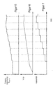
- FIGS. 5 to 7 show the change in the voltages during the adjustment.
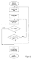
- FIG. 1 shows a flow chart of the method.
- the procedural step “Adjustment” is shown in detail in FIG. 2. The following will the sequence of the method according to Figures 1 and 2 described.
- the capacitors become the receiving resonant circuit added for which the maximum rectified and smoothed Voltage Vtp was stored in the memory.
- the coil voltage Vcoil is rectified and smoothed using a low pass.
- the voltage Vtp, 1 thus generated becomes provisionally stored as a reference value in a first memory SP.
- the second memory makes the configuration of the capacitors Cn unique descriptive reference number filed.
- capacitors Cn parallel to the LC resonant circuit of the receiving resonant circuit switched. This changes its resonance frequency and thus the induced coil voltage Vcoil and finally also the rectified and smoothed voltage Vtp.
- By switching on of a first capacitor C1 changes with the resonance frequency of the receiving resonant circuit also the one used for the evaluation Voltage Vtp.
- This new, modified, available at a second point in time Voltage Vtp, 2 is compared to the previous one by means of a comparator, Voltage Vtp, 1 stored in the memory compared. Is that in the second Voltage Vtp, 2 present at the time is greater than that stored in the memory value, the new voltage becomes Vtp, 2 instead of the previous voltage Vtp, 1 and the new one, which clearly describes the configuration of the capacitors Cn Reference number written in memory, the next capacitor added and the comparison with the new pair of values, the new, third voltage Vtp, 3 and the value of the stored in the memory second voltage Vtp, 2, repeated.
- This method of comparison is particularly preferable if when the query signal is switched on or when the transponder is immersed a certain temporal behavior of the transponder in a query field it is asked for.
- FIG. 3 shows a first embodiment of a circuit arrangement for performing the method in the block diagram.
- the receiving resonant circuit of the transponder consists of at least one inductor and at least one capacitance and is connected to the circuit arrangement via the Coil1 / Coil2 connection pair.
- This consists of a large number of capacitances which can be connected in parallel to the capacitance of the receiving resonant circuit by means of controllable switches - represented in FIG. 3 by the circuit block with the name Adapt.
- a low-pass filter is also connected to the connection pair Coil1 / Coil2 - shown in FIG. 3 by the circuit block with the designation front2.
- the output signal Vtp of the low-pass filter is fed to a comparator stage - shown in FIG. 3 by the circuit block called max_detect.
- the output signal Vtp of the low-pass filter is compared with the previously occurring maximum value stored there.
- the large number of capacitances are controlled adaptively.
- FIG. 4 shows the circuit arrangement again in an improved Presentation. Only the functional units of the transponder are shown which contribute significantly to the function of the comparison.
- the receiving resonant circuit 1 of the transponder consisting of at least one inductor and at least one capacity, forms with that, not shown Resonance circuit of the reader a loosely coupled transformer.
- Parallel the capacitance of the receiving resonant circuit 1 is a large number of capacitances 2, by controllable switch to the capacity of the receiving resonant circuit are switchable, arranged.
- the switches are activated through a control logic 6.
- the control logic 6 also gets one from the Interrogation signal generated clock signal supplied.
- the receiving resonant circuit 1 is still with a Rectifier stage 3 and a clock generator circuit 7 connected.
- the rectified signal from rectifier stage 3 becomes a filter stage 4 fed for smoothing.
- the filter stage is designed as a low-pass filter.
- the such rectified and smoothed signal is the input of a maximum detector 5 fed.
- the maximum detector compares this to his Input pending signal with a stored size and takes over the larger one in its memory. As a result, the memory contains of the maximum detector always the largest value of the rectified and smoothed signal since the start of the adjustment.
- the maximum detector 5 is connected to the control logic 6. This sets the switchable capacitors so that again the maximum value is achieved and shows at another output that the adjustment is finished.
- the switchable capacities advantageously consist of a series connection a capacitor and a switching transistor, the switching transistor is controlled by the control logic.
- One pair each of the same size Capacitors are controlled by the control logic, the first series connection of capacitor and switching transistor each connects the first connection of the receiving resonant circuit to the ground potential and the second series connection of capacitor and switching transistor the second connection of the receiving resonant circuit with the ground potential combines.
- the control logic contains an n-level Dual counter, the outputs of which control n pairs of capacitors / switches.
- the values of the individual pairs of capacitors are chosen so that they are graded in binary weighted pairs and thus one cover a wide range of values. For example, a four-step binary would Control 4 pairs of capacitors at its outputs.
- the Capacities then correspond to the assigned meter levels and are one, two, four and eight times a base value, for example 10 pF. With such an arrangement, the receiving resonant circuit can be next to its basic setting can be changed in 15 steps.
- all capacitors are equally sized. They can then be controlled directly or be connected together in groups, the ones described above correspond to binary weighted values.
- the receiving resonant circuit of a transponder to tune to the interrogation signal in response to frequency. This comparison can be done every time the transponder is started up, or by a given command can be triggered by the reader. Also for one-off, factory adjustment to a predetermined frequency around the Component tolerances of the receiving resonant circuit can compensate for procedures and circuit arrangement are used. Then the through a setting determined once, e.g. the counter reading of the the switches of the counter driving the capacitors, in a read-only memory of the transponder is saved permanently and with every initialization used again to control the capacitors.
Abstract
Description
- Sendeenergie (beschränkt durch gesetzliche Bestimmungen)
- Spulenabmessungen
- Störpegel der Umgebung
- Übereinstimmung der Resonanzfrequenzen
- Modulationshub
- Spannungsverlust über den Gleichrichter
- Verwendete Übertragungsverfahren
- Figur 1
- Ablaufdiagramm des Verfahrens
- Figur 2
- Ablauf des Abgleichs gemäß einen zweiten Aufgestaltung des Verfahrens
- Figur 3
- zeigt ein Blockschaltbild einer ersten Schaltungsanordnung zur Durchführung des Verfahrens;
- Figur 4
- zeigt ein Blockschaltbild der Schaltungsanordnung einer zweiten Schaltungsanordnung zur Durchführung des Verfahrens;
- Figur 5 zeigt
- die Änderung der Spulenspannung Vvcil1/2 beim Ablauf des Abgleichs;
- Figur 6
- zeigt die Änderung der Ausgangsspannung der Filterstufe beim Ablauf des Abgleichs;
- Figur 7
- zeigt die Änderung der Gesamtkapazität des Empfangsschwingkreises beim Ablauf des Abgleichs;
- Gleiche Resonanzfrequenz von Basisstation und Transponder
- Zeitlich optimierte Übertragungsprotokolle
- Minimale Verluste bei der Energieübertragung
- Maximaler Modulationshub bei der Datenübertragung zur Basisstation (Read)
- Optimierte Datenübertragung zum Transponder (Send)
Der Empfangsschwingkreises des Transponders besteht aus mindestens einer Induktivität und mindestens einer Kapazität und wird über das Anschlußpaar Coil1/Coil2 mit der Schaltungsanordnung verbunden. Diese besteht aus einer Vielzahl von Kapazitäten, die durch ansteuerbare Schalter parallel zur Kapazität des Empfangsschwingkreis schaltbar sind ― dargestellt in der Figur 3 durch den Schaltungsblock mit der Bezeichnung Adapt. Ebenfalls mit dem Anschlußpaar Coil1/Coil2 ist ein Tiefpaßfilter verbunden ― dargestellt in der Figur 3 durch den Schaltungsblock mit der Bezeichnung front2. Das Ausgangssignal Vtp des Tiefpaßfilters wird einer Komparatorstufe zugeführt ― dargestellt in der Figur 3 durch den Schaltungsblock mit der Bezeichnung max_detect. In der Komparatorstufe wird das Ausgangssignal Vtp des Tiefpaßfilters mit dem dort gespeicherten, bisher aufgetretenen Maximalwert verglichen. In Abhängigkeit von dessen Ausgangssignal adapt_out werden die Vielzahl von Kapazitäten adapt angesteuert.
Claims (5)
- Verfahren zum Abgleich eines Empfangsschwingkreises eines Transponders in einem RFID System auf Resonanz zu der Frequenz eines von einem Lesegerät ausgesendeten Abfragesignals, wobei der Empfangsschwingkreises aus mindestens einer Induktivität und aus mindestens einer Kapazität besteht, wobei die Kapazität des Empfangsschwingkreises schrittweise durch hinzu- bzw. hinwegschalten einer Vielzahl von einzelnen Kondensatoren geändert und schließlich so eingestellt wird, daß das vom Transponder empfangene Abfragesignal einen innerhalb des Änderungsbereiches maximalen Spannungswert annimmt, und wobei die Kapazitätswerte der Kondensatoren binär gewichtet abgestuft sind und die Ansteuerung der Kondensatoren durch binäres Zählen erfolgt.
dadurch gekennzeichnet, daß zum Abgleich alle werte der Kondensatoren im Änderungsbereich geschaltet werden, der Zählerstand beim maximalen Spannungswert festgehalten und schließlich die Kondensatoransteuerung für diesen Zählerstand eingestellt wird. - Verfahren nach Anspruch 1, dadurch gekennzeichnet, daß der Abgleich unmittelbar nach Beginn des Empfangs des Abfragesignals durchgeführt wird.
- Verfahren nach Anspruch 1, dadurch gekennzeichnet, daß der Abgleich nach dem Empfang eines entsprechenden, vom Lesegerät gesendeten Kommandos durchgeführt wird.
- Verfahren nach einem der Ansprüche 1-3, dadurch gekennzeichnet, daß der Abgleich von größeren Frequenzen hin zu kleineren Frequenzen erfolgt.
- Verfahren nach einem der Ansprüche 1-3, dadurch gekennzeichnet, daß der Abgleich von kleineren Frequenzen hin zu größeren Frequenzen erfolgt.
Applications Claiming Priority (3)
| Application Number | Priority Date | Filing Date | Title |
|---|---|---|---|
| DE19637319 | 1996-09-13 | ||
| DE19637319 | 1996-09-13 | ||
| PCT/EP1997/005011 WO1998011505A1 (de) | 1996-09-13 | 1997-09-13 | Verfahren zum abgleich eines empfangsschwingkreises eines transponders in einem rfid system |
Publications (2)
| Publication Number | Publication Date |
|---|---|
| EP0925551A1 EP0925551A1 (de) | 1999-06-30 |
| EP0925551B1 true EP0925551B1 (de) | 2002-07-24 |
Family
ID=7805530
Family Applications (3)
| Application Number | Title | Priority Date | Filing Date |
|---|---|---|---|
| EP97942920A Expired - Lifetime EP0925551B1 (de) | 1996-09-13 | 1997-09-13 | Verfahren zum abgleich eines empfangsschwingkreises eines transponders in einem rfid system |
| EP97909259A Expired - Lifetime EP0925665B1 (de) | 1996-09-13 | 1997-09-13 | Verfahren zur kryptologischen authentifizierung in einem radiofrequenz-identifikations-system |
| EP97944877A Expired - Lifetime EP0925548B1 (de) | 1996-09-13 | 1997-09-13 | Verfahren zum übertragen von daten in einem radiofrequenz identifikations-system |
Family Applications After (2)
| Application Number | Title | Priority Date | Filing Date |
|---|---|---|---|
| EP97909259A Expired - Lifetime EP0925665B1 (de) | 1996-09-13 | 1997-09-13 | Verfahren zur kryptologischen authentifizierung in einem radiofrequenz-identifikations-system |
| EP97944877A Expired - Lifetime EP0925548B1 (de) | 1996-09-13 | 1997-09-13 | Verfahren zum übertragen von daten in einem radiofrequenz identifikations-system |
Country Status (7)
| Country | Link |
|---|---|
| US (3) | US6426692B1 (de) |
| EP (3) | EP0925551B1 (de) |
| JP (3) | JP2001501051A (de) |
| AU (4) | AU4458297A (de) |
| DE (3) | DE59707804D1 (de) |
| ES (3) | ES2172769T3 (de) |
| WO (4) | WO1998011553A1 (de) |
Cited By (1)
| Publication number | Priority date | Publication date | Assignee | Title |
|---|---|---|---|---|
| DE102010043968A1 (de) | 2010-11-16 | 2012-05-16 | Aug. Winkhaus Gmbh & Co. Kg | Verfahren zum Abgleich eines Empfangsschwingkreises eines Transponders in einem RFID-System |
Families Citing this family (63)
| Publication number | Priority date | Publication date | Assignee | Title |
|---|---|---|---|---|
| JPH10187916A (ja) * | 1996-12-27 | 1998-07-21 | Rohm Co Ltd | 非接触icカード通信システムにおける応答器 |
| DE19910875A1 (de) * | 1999-03-11 | 2000-09-21 | Siemens Ag | System zur berührungslosen, seriellen Übertragung von Daten aus insbesondere schnell bewegten, mobilen Datenträgern, und bevorzugte Verwendungen des Systems |
| FR2792132B1 (fr) | 1999-04-07 | 2001-11-02 | St Microelectronics Sa | Borne de lecture d'un transpondeur electromagnetique fonctionnant en couplage tres proche |
| US6650226B1 (en) | 1999-04-07 | 2003-11-18 | Stmicroelectronics S.A. | Detection, by an electromagnetic transponder reader, of the distance separating it from a transponder |
| FR2792136B1 (fr) | 1999-04-07 | 2001-11-16 | St Microelectronics Sa | Transmission en duplex dans un systeme de transpondeurs electromagnetiques |
| FR2792135B1 (fr) * | 1999-04-07 | 2001-11-02 | St Microelectronics Sa | Fonctionnement en complage tres proche d'un systeme a transpondeur electromagnetique |
| FR2796781A1 (fr) | 1999-07-20 | 2001-01-26 | St Microelectronics Sa | Dimensionnement d'un systeme a transpondeur electromagnetique pour un fonctionnement en hyperproximite |
| US7049935B1 (en) | 1999-07-20 | 2006-05-23 | Stmicroelectronics S.A. | Sizing of an electromagnetic transponder system for a dedicated distant coupling operation |
| SE515391C2 (sv) * | 1999-11-08 | 2001-07-23 | Tagmaster Ab | Identifieringsbricka och läsare med interferensskydd |
| FR2804557B1 (fr) * | 2000-01-31 | 2003-06-27 | St Microelectronics Sa | Adaptation de la puissance d'emission d'un lecteur de transpondeur electromagnetique |
| EP1124206A1 (de) * | 2000-02-08 | 2001-08-16 | Infineon Technologies AG | Verfahren und Anordnung zur gegenseitigen Authentifizierung zweier Datenverarbeitungseinheiten |
| FR2808945B1 (fr) | 2000-05-12 | 2002-08-16 | St Microelectronics Sa | Evaluation du nombre de transpondeurs electromagnetiques dans le champ d'un lecteur |
| FR2808941B1 (fr) | 2000-05-12 | 2002-08-16 | St Microelectronics Sa | Validation de la presence d'un transpondeur electromagnetique dans le champ d'un lecteur a demodulation d'amplitude |
| FR2808942B1 (fr) * | 2000-05-12 | 2002-08-16 | St Microelectronics Sa | Validation de la presence d'un transpondeur electromagnetique dans le champ d'un lecteur a demodulation de phase |
| FR2808946A1 (fr) | 2000-05-12 | 2001-11-16 | St Microelectronics Sa | Validation de la presence d'un transpondeur electromagnetique dans le champ d'un lecteur |
| FR2809251B1 (fr) * | 2000-05-17 | 2003-08-15 | St Microelectronics Sa | Dispositif de production d'un champ electromagnetique pour transpondeur |
| FR2809235A1 (fr) * | 2000-05-17 | 2001-11-23 | St Microelectronics Sa | Antenne de generation d'un champ electromagnetique pour transpondeur |
| FR2812986B1 (fr) * | 2000-08-09 | 2002-10-31 | St Microelectronics Sa | Detection d'une signature electrique d'un transpondeur electromagnetique |
| US20030169169A1 (en) * | 2000-08-17 | 2003-09-11 | Luc Wuidart | Antenna generating an electromagnetic field for transponder |
| US6989750B2 (en) * | 2001-02-12 | 2006-01-24 | Symbol Technologies, Inc. | Radio frequency identification architecture |
| US6961000B2 (en) * | 2001-07-05 | 2005-11-01 | Amerasia International Technology, Inc. | Smart tag data encoding method |
| US6994783B2 (en) * | 2001-12-31 | 2006-02-07 | Clark Joseph Use | Water pollution trap with inlet basket |
| US7098808B2 (en) * | 2002-09-30 | 2006-08-29 | Aviation Communication & Surveillance Systems, Llc | System having termination for data loading port |
| JP4705317B2 (ja) * | 2003-04-16 | 2011-06-22 | 株式会社東海理化電機製作所 | スイッチ装置、セキュリティシステム |
| US7515881B2 (en) * | 2003-11-26 | 2009-04-07 | Starkey Laboratories, Inc. | Resonance frequency shift canceling in wireless hearing aids |
| TWI283524B (en) * | 2004-04-09 | 2007-07-01 | Lite On Technology Corp | Method to control and manage an authentication mechanism using an active identification device |
| US7602274B2 (en) * | 2004-04-23 | 2009-10-13 | Microchip Technology Incorporated | Dynamic configuration of a radio frequency transponder |
| KR20050104652A (ko) * | 2004-04-29 | 2005-11-03 | 삼성에스디아이 주식회사 | 전자 방출 표시 장치 및 그 구동 방법 |
| US7493619B1 (en) | 2004-08-09 | 2009-02-17 | The Mathworks, Inc. | Methods for transmitting data between tasks of differing priority in a graphical modeling environment |
| JP4736398B2 (ja) * | 2004-10-22 | 2011-07-27 | 日本電気株式会社 | 近接する端末間における認証方法、秘匿情報の配送方法、装置、システム、及び、プログラム |
| US7339476B2 (en) | 2004-11-10 | 2008-03-04 | Rockwell Automation Technologies, Inc. | Systems and methods that integrate radio frequency identification (RFID) technology with industrial controllers |
| US7551081B2 (en) | 2004-11-10 | 2009-06-23 | Rockwell Automation Technologies, Inc. | Systems and methods that integrate radio frequency identification (RFID) technology with agent-based control systems |
| US7613927B2 (en) * | 2004-11-12 | 2009-11-03 | Raritan Americas, Inc. | System for providing secure access to KVM switch and other server management systems |
| JP3765544B1 (ja) | 2004-11-26 | 2006-04-12 | 株式会社ソニー・コンピュータエンタテインメント | バッテリ、及び認証要求装置 |
| DE102005005812A1 (de) * | 2005-02-09 | 2006-08-17 | Atmel Germany Gmbh | Schaltungsanordnung und Verfahren zur Spannungsversorgung eines Transponders |
| US7689195B2 (en) * | 2005-02-22 | 2010-03-30 | Broadcom Corporation | Multi-protocol radio frequency identification transponder tranceiver |
| US7636044B1 (en) | 2005-05-13 | 2009-12-22 | Rockwell Automation Technologies, Inc. | RFID tag programming, printing application, and supply chain/global registration architecture |
| US7616117B2 (en) | 2005-07-19 | 2009-11-10 | Rockwell Automation Technologies, Inc. | Reconciliation mechanism using RFID and sensors |
| US7388491B2 (en) * | 2005-07-20 | 2008-06-17 | Rockwell Automation Technologies, Inc. | Mobile RFID reader with integrated location awareness for material tracking and management |
| US7764191B2 (en) | 2005-07-26 | 2010-07-27 | Rockwell Automation Technologies, Inc. | RFID tag data affecting automation controller with internal database |
| US8260948B2 (en) | 2005-08-10 | 2012-09-04 | Rockwell Automation Technologies, Inc. | Enhanced controller utilizing RFID technology |
| US7510110B2 (en) * | 2005-09-08 | 2009-03-31 | Rockwell Automation Technologies, Inc. | RFID architecture in an industrial controller environment |
| US7931197B2 (en) * | 2005-09-20 | 2011-04-26 | Rockwell Automation Technologies, Inc. | RFID-based product manufacturing and lifecycle management |
| US7446662B1 (en) | 2005-09-26 | 2008-11-04 | Rockwell Automation Technologies, Inc. | Intelligent RFID tag for magnetic field mapping |
| US8025227B2 (en) * | 2005-09-30 | 2011-09-27 | Rockwell Automation Technologies, Inc. | Access to distributed databases via pointer stored in RFID tag |
| FR2906952B1 (fr) * | 2006-10-05 | 2009-02-27 | Inside Contactless Sa | Procede d'authentification mutuelle entre une interface de communication et un processeur hote d'un chipset nfc. |
| US7586385B2 (en) * | 2006-11-18 | 2009-09-08 | Rfmicron, Inc. | Method and apparatus for varying an impedance |
| US10224902B2 (en) | 2006-11-18 | 2019-03-05 | Rfmicron, Inc. | Roll-to-roll production of RFID tags |
| US20080280560A1 (en) * | 2007-05-09 | 2008-11-13 | Micron Technology, Inc. | Method and system of placing a rfid tag in a continuous transmission mode |
| DE102007051792B4 (de) * | 2007-10-30 | 2012-01-12 | Texas Instruments Deutschland Gmbh | Selbstkalibrierender RFID-Transponder und Verfahren zur Selbstkalibrierung eines RFID-Transponders |
| CN101159639B (zh) * | 2007-11-08 | 2010-05-12 | 西安西电捷通无线网络通信有限公司 | 一种单向接入认证方法 |
| JP2009141729A (ja) * | 2007-12-07 | 2009-06-25 | Panasonic Corp | 検波用回路装置および携帯機器 |
| US20090160648A1 (en) * | 2007-12-24 | 2009-06-25 | Rfmicron, Inc. | Method and apparatus for bulk calibrating RFID tags |
| US8635452B2 (en) * | 2008-08-19 | 2014-01-21 | Nxp B.V. | Method for generating a cipher-based message authentication code |
| DE102009051201B4 (de) * | 2009-10-29 | 2012-12-20 | Siemens Aktiengesellschaft | Authentifikation und Datenintegritätschutz eines Tokens |
| CA2798951C (en) * | 2010-07-08 | 2016-05-10 | Certicom Corp. | System and method for performing device authentication using key agreement |
| DE102010037944B4 (de) | 2010-10-04 | 2018-03-08 | Dr. Hahn Gmbh & Co. Kg | Verfahren und Vorrichtung zur kontaktlosen Übertragung von elektrischer Energie und/oder elektrischen Signalen zwischen einer Wand und einem an dieser Wand befestigten Flügel |
| US9214274B2 (en) | 2010-10-04 | 2015-12-15 | Dr. Hahn Gmbh & Co. Kg | Method and apparatus for transmitting signals between a wall and a leaf fastened to this wall using hinges around a hinge axis |
| US9808730B2 (en) * | 2011-10-31 | 2017-11-07 | Traxxas Lp | Multi-function electronic device-enabled transmit controller |
| DE102012015406A1 (de) * | 2012-08-01 | 2014-02-06 | Gantner Electronic Gmbh | Verfahren und Vorrichtung zur Optimierung des RFID-Feldes einer Zugangskontrolleinrichtung |
| SI24189A (sl) | 2012-09-05 | 2014-03-31 | Ams R&D Analogni Polprevodniki, D.O.O. | Postopek in vezje za uglasitev antenskega vezja aktivno oddajajoče nalepke |
| US10137860B2 (en) * | 2016-11-17 | 2018-11-27 | Ford Global Technologies, Llc | Remote keyless entry message authentication |
| DE102018002157A1 (de) * | 2018-03-16 | 2019-09-19 | Zf Active Safety Gmbh | Vorrichtung und Verfahren zur verschlüsselten Übertragung eines digitalen Steuersignals von einem Kraftfahrzeugschlüssel an ein Kraftfahrzeug |
Family Cites Families (23)
| Publication number | Priority date | Publication date | Assignee | Title |
|---|---|---|---|---|
| US3605091A (en) * | 1969-09-18 | 1971-09-14 | Bell Telephone Labor Inc | Feedback error control arrangement |
| US5282249A (en) * | 1989-11-14 | 1994-01-25 | Michael Cohen | System for controlling access to broadcast transmissions |
| FR2662320B1 (fr) * | 1990-05-18 | 1994-05-13 | Cemagref | Dispositif de liaison sans contact pour relier des troncons de bus serie. |
| DE4114777A1 (de) * | 1990-05-22 | 1992-02-06 | Peter Elsner | Verfahren und einrichtung zur nachrichtenumschluesselung |
| US5309516A (en) * | 1990-12-07 | 1994-05-03 | Hitachi, Ltd. | Group cipher communication method and group cipher communication system |
| JP3100716B2 (ja) * | 1991-01-04 | 2000-10-23 | シーエスアイアール | 識別装置 |
| EP0505653A1 (de) * | 1991-03-29 | 1992-09-30 | International Business Machines Corporation | Kombinierte Abfühlverstärker und Verriegelungsschaltung für sehr schnelle ROM-Speicher |
| US5365589A (en) * | 1992-02-07 | 1994-11-15 | Gutowitz Howard A | Method and apparatus for encryption, decryption and authentication using dynamical systems |
| US5313521A (en) * | 1992-04-15 | 1994-05-17 | Fujitsu Limited | Key distribution protocol for file transfer in the local area network |
| NL9202069A (nl) | 1992-11-30 | 1994-06-16 | Nedap Nv | Identificatiesysteem met verbeterde identificatie-algorithme. |
| DE4317380C1 (de) * | 1993-05-25 | 1994-08-18 | Siemens Ag | Verfahren zur Authentifikation zwischen zwei elektronischen Einrichtungen |
| US5491715A (en) * | 1993-06-28 | 1996-02-13 | Texas Instruments Deutschland Gmbh | Automatic antenna tuning method and circuit |
| US5517194A (en) * | 1994-02-10 | 1996-05-14 | Racom Systems, Inc. | Passive RF transponder and method |
| EP0683293A1 (de) | 1994-05-03 | 1995-11-22 | TEMIC TELEFUNKEN microelectronic GmbH | Verfahren zum Betrieb eines Datenübertragungssystems aus einem Transponder und einem Lesegerät |
| US5530702A (en) | 1994-05-31 | 1996-06-25 | Ludwig Kipp | System for storage and communication of information |
| US5550536A (en) * | 1994-08-17 | 1996-08-27 | Texas Instruments Deutschland Gmbh | Circuit frequency following technique transponder resonant |
| JPH08101867A (ja) * | 1994-09-30 | 1996-04-16 | Fujitsu Ltd | ソフトウェア利用許可システム |
| DE4438287C1 (de) * | 1994-10-26 | 1996-05-09 | Siemens Ag | System zur kontaktlosen Energie- und Datenübertragung |
| DE4438286C2 (de) * | 1994-10-26 | 2002-09-12 | Siemens Ag | System zur kontaktlosen Energie- und Datenübertragung |
| DE19502373C2 (de) | 1995-01-26 | 1997-07-03 | Telefunken Microelectron | Verfahren zur Diebstahlsicherung motorangetriebener Kraftfahrzeuge |
| US5583819A (en) * | 1995-01-27 | 1996-12-10 | Single Chip Holdings, Inc. | Apparatus and method of use of radiofrequency identification tags |
| US5673018A (en) * | 1995-06-07 | 1997-09-30 | Palomar Technologies Corporation | Transponder system for reporting the distance traveled by a wheeled vehicle |
| JP3086887B2 (ja) * | 1996-08-08 | 2000-09-11 | 株式会社ローレルインテリジェントシステムズ | 情報伝達方法、情報発信方法、情報再生方法及び通信装置 |
-
1997
- 1997-09-13 US US09/254,867 patent/US6426692B1/en not_active Expired - Lifetime
- 1997-09-13 WO PCT/EP1997/005013 patent/WO1998011553A1/de active Application Filing
- 1997-09-13 EP EP97942920A patent/EP0925551B1/de not_active Expired - Lifetime
- 1997-09-13 AU AU44582/97A patent/AU4458297A/en not_active Abandoned
- 1997-09-13 JP JP10513274A patent/JP2001501051A/ja active Pending
- 1997-09-13 DE DE59707804T patent/DE59707804D1/de not_active Expired - Lifetime
- 1997-09-13 EP EP97909259A patent/EP0925665B1/de not_active Expired - Lifetime
- 1997-09-13 ES ES97909259T patent/ES2172769T3/es not_active Expired - Lifetime
- 1997-09-13 WO PCT/EP1997/005011 patent/WO1998011505A1/de active IP Right Grant
- 1997-09-13 JP JP51327398A patent/JP3867251B2/ja not_active Expired - Fee Related
- 1997-09-13 AU AU47029/97A patent/AU4702997A/en not_active Abandoned
- 1997-09-13 ES ES97942920T patent/ES2179369T3/es not_active Expired - Lifetime
- 1997-09-13 DE DE59703244T patent/DE59703244D1/de not_active Expired - Lifetime
- 1997-09-13 WO PCT/EP1997/005010 patent/WO1998011496A1/de active IP Right Grant
- 1997-09-13 US US09/254,865 patent/US6510517B1/en not_active Expired - Lifetime
- 1997-09-13 AU AU44583/97A patent/AU4458397A/en not_active Abandoned
- 1997-09-13 ES ES97944877T patent/ES2157089T3/es not_active Expired - Lifetime
- 1997-09-13 AU AU46228/97A patent/AU4622897A/en not_active Abandoned
- 1997-09-13 US US09/254,866 patent/US6272321B1/en not_active Expired - Lifetime
- 1997-09-13 DE DE59706402T patent/DE59706402D1/de not_active Expired - Lifetime
- 1997-09-13 EP EP97944877A patent/EP0925548B1/de not_active Expired - Lifetime
- 1997-09-13 WO PCT/EP1997/005012 patent/WO1998011689A2/de active IP Right Grant
- 1997-09-13 JP JP51327598A patent/JP3890510B2/ja not_active Expired - Fee Related
Cited By (2)
| Publication number | Priority date | Publication date | Assignee | Title |
|---|---|---|---|---|
| DE102010043968A1 (de) | 2010-11-16 | 2012-05-16 | Aug. Winkhaus Gmbh & Co. Kg | Verfahren zum Abgleich eines Empfangsschwingkreises eines Transponders in einem RFID-System |
| EP2453392A2 (de) | 2010-11-16 | 2012-05-16 | Aug. Winkhaus GmbH & Co. KG | Verfahren zum Abgleich eines Empfangsschwingkreises eines Transponders in einem RFID-System |
Also Published As
| Publication number | Publication date |
|---|---|
| AU4458397A (en) | 1998-04-02 |
| US6272321B1 (en) | 2001-08-07 |
| JP2001500685A (ja) | 2001-01-16 |
| EP0925548A1 (de) | 1999-06-30 |
| EP0925665B1 (de) | 2002-02-13 |
| EP0925665A2 (de) | 1999-06-30 |
| JP2001501051A (ja) | 2001-01-23 |
| ES2157089T3 (es) | 2001-08-01 |
| DE59706402D1 (de) | 2002-03-21 |
| ES2179369T3 (es) | 2003-01-16 |
| AU4458297A (en) | 1998-04-02 |
| WO1998011496A1 (de) | 1998-03-19 |
| JP2001501391A (ja) | 2001-01-30 |
| WO1998011689A2 (de) | 1998-03-19 |
| JP3867251B2 (ja) | 2007-01-10 |
| EP0925548B1 (de) | 2001-03-28 |
| DE59707804D1 (de) | 2002-08-29 |
| US6510517B1 (en) | 2003-01-21 |
| JP3890510B2 (ja) | 2007-03-07 |
| EP0925551A1 (de) | 1999-06-30 |
| WO1998011689A3 (de) | 1998-05-14 |
| WO1998011553A1 (de) | 1998-03-19 |
| WO1998011505A1 (de) | 1998-03-19 |
| ES2172769T3 (es) | 2002-10-01 |
| DE59703244D1 (de) | 2001-05-03 |
| AU4702997A (en) | 1998-04-02 |
| US6426692B1 (en) | 2002-07-30 |
| AU4622897A (en) | 1998-04-02 |
Similar Documents
| Publication | Publication Date | Title |
|---|---|---|
| EP0925551B1 (de) | Verfahren zum abgleich eines empfangsschwingkreises eines transponders in einem rfid system | |
| EP0788633B1 (de) | System zur kontaktlosen energie- und datenübertragung | |
| DE60103079T2 (de) | Kontaktloses lesegerät für integrierte schaltung | |
| EP0590122B1 (de) | Verfahren zur übertragung serieller datenstrukturen für informationsträgeridentifikationssysteme, danach arbeitendes übertragungssystem und informationsträger | |
| DE60312208T2 (de) | Abstimmbare antennenschaltung, insbesondere für ein kontaktloses integriertes lesegerät | |
| DE4438286C1 (de) | System zur kontaktlosen Energie- und Datenübertragung | |
| DE19614455A1 (de) | Verfahren zum Betrieb eines Systems aus einer Basisstation und einem damit kontaktlos gekoppelten Transponders sowie dafür geeignetes System | |
| DE102005005812A1 (de) | Schaltungsanordnung und Verfahren zur Spannungsversorgung eines Transponders | |
| DE69936439T2 (de) | Kapazitive Modulation in einem elektromagnetischen Transponder | |
| DE102009021329B4 (de) | Halbduplex-RFID-Transponder und Verfahren zum Betreiben eines Halbduplex-RFID-Transponders | |
| WO2015052033A1 (de) | Treiberschaltung für eine induktivität, verfahren zum betreiben einer induktivität und aktive sendeeinrichtung mit einer treiberschaltung | |
| EP1344178B1 (de) | Vorrichtung und verfahren zum gleichzeitigen auslesen von passiven induktiven transpondern | |
| EP2115704B1 (de) | Güteanpassung eines empfangsschaltkreises | |
| DE19602316C1 (de) | Vorrichtung zum Übertragen von Daten oder Energie | |
| DE60007291T2 (de) | Schaltungsanordnung zum empfangen und senden von daten mit induktiver kopplung | |
| DE60125088T2 (de) | Lesegerät mit Mitteln zur Bestimmung der Anzahl von elektromagnetischen Transpondern im Felde des Lesegerätes | |
| DE112013004357T5 (de) | Verfahren und Schaltung zum Abstimmen einer Antennenschaltung eines aktiv sendenden Tags | |
| DE69915270T2 (de) | Vorrichtung zur Kontrolle der auf die Antenne zurückgeführten Impedanz eines elektronischen Etiketts | |
| DE10345497B4 (de) | Oszillatorschaltung, insbesondere für den Mobilfunk | |
| DE19755250A1 (de) | Schaltungsanordnung zum Einstellen der Resonanzfrequenz | |
| DE19800565A1 (de) | Datenübertragungssystem mit einem beweglichen Transponder und einer Basisstation | |
| WO1998011504A1 (de) | Passiver transponder | |
| DE19715956A1 (de) | Eingangsschaltung für einen Fernsehtuner | |
| WO1998010364A1 (de) | Verfahren zur kommunikation zwischen berührungslos arbeitenden chipkarten und kartenendgeräten und kommunikationssystem hierzu | |
| DE102008031149A1 (de) | Tragbarer Datenträger mit aktiver Kontaktlosschnittstelle und Verfahren zum Betreiben |
Legal Events
| Date | Code | Title | Description |
|---|---|---|---|
| PUAI | Public reference made under article 153(3) epc to a published international application that has entered the european phase |
Free format text: ORIGINAL CODE: 0009012 |
|
| 17P | Request for examination filed |
Effective date: 19990131 |
|
| AK | Designated contracting states |
Kind code of ref document: A1 Designated state(s): DE ES FR GB IT |
|
| RAP1 | Party data changed (applicant data changed or rights of an application transferred) |
Owner name: TEMIC TELEFUNKEN MICROELECTRONIC GMBH |
|
| 17Q | First examination report despatched |
Effective date: 20000602 |
|
| RAP1 | Party data changed (applicant data changed or rights of an application transferred) |
Owner name: TEMIC SEMICONDUCTOR GMBH |
|
| RAP1 | Party data changed (applicant data changed or rights of an application transferred) |
Owner name: ATMEL GERMANY GMBH |
|
| GRAG | Despatch of communication of intention to grant |
Free format text: ORIGINAL CODE: EPIDOS AGRA |
|
| GRAG | Despatch of communication of intention to grant |
Free format text: ORIGINAL CODE: EPIDOS AGRA |
|
| GRAH | Despatch of communication of intention to grant a patent |
Free format text: ORIGINAL CODE: EPIDOS IGRA |
|
| GRAH | Despatch of communication of intention to grant a patent |
Free format text: ORIGINAL CODE: EPIDOS IGRA |
|
| GRAA | (expected) grant |
Free format text: ORIGINAL CODE: 0009210 |
|
| AK | Designated contracting states |
Kind code of ref document: B1 Designated state(s): DE ES FR GB IT |
|
| REG | Reference to a national code |
Ref country code: GB Ref legal event code: FG4D Free format text: NOT ENGLISH |
|
| REF | Corresponds to: |
Ref document number: 59707804 Country of ref document: DE Date of ref document: 20020829 |
|
| GBT | Gb: translation of ep patent filed (gb section 77(6)(a)/1977) |
Effective date: 20020919 |
|
| ET | Fr: translation filed | ||
| REG | Reference to a national code |
Ref country code: ES Ref legal event code: FG2A Ref document number: 2179369 Country of ref document: ES Kind code of ref document: T3 |
|
| PLBE | No opposition filed within time limit |
Free format text: ORIGINAL CODE: 0009261 |
|
| STAA | Information on the status of an ep patent application or granted ep patent |
Free format text: STATUS: NO OPPOSITION FILED WITHIN TIME LIMIT |
|
| 26N | No opposition filed |
Effective date: 20030425 |
|
| PGFP | Annual fee paid to national office [announced via postgrant information from national office to epo] |
Ref country code: GB Payment date: 20040907 Year of fee payment: 8 |
|
| PGFP | Annual fee paid to national office [announced via postgrant information from national office to epo] |
Ref country code: FR Payment date: 20040910 Year of fee payment: 8 |
|
| PGFP | Annual fee paid to national office [announced via postgrant information from national office to epo] |
Ref country code: ES Payment date: 20040920 Year of fee payment: 8 |
|
| PG25 | Lapsed in a contracting state [announced via postgrant information from national office to epo] |
Ref country code: GB Free format text: LAPSE BECAUSE OF NON-PAYMENT OF DUE FEES Effective date: 20050913 |
|
| PG25 | Lapsed in a contracting state [announced via postgrant information from national office to epo] |
Ref country code: ES Free format text: LAPSE BECAUSE OF NON-PAYMENT OF DUE FEES Effective date: 20050914 |
|
| GBPC | Gb: european patent ceased through non-payment of renewal fee |
Effective date: 20050913 |
|
| PG25 | Lapsed in a contracting state [announced via postgrant information from national office to epo] |
Ref country code: FR Free format text: LAPSE BECAUSE OF NON-PAYMENT OF DUE FEES Effective date: 20060531 |
|
| REG | Reference to a national code |
Ref country code: FR Ref legal event code: ST Effective date: 20060531 |
|
| REG | Reference to a national code |
Ref country code: ES Ref legal event code: FD2A Effective date: 20050914 |
|
| PGFP | Annual fee paid to national office [announced via postgrant information from national office to epo] |
Ref country code: IT Payment date: 20070925 Year of fee payment: 11 |
|
| PG25 | Lapsed in a contracting state [announced via postgrant information from national office to epo] |
Ref country code: IT Free format text: LAPSE BECAUSE OF NON-PAYMENT OF DUE FEES Effective date: 20080913 |
|
| PGFP | Annual fee paid to national office [announced via postgrant information from national office to epo] |
Ref country code: DE Payment date: 20120927 Year of fee payment: 16 |
|
| REG | Reference to a national code |
Ref country code: DE Ref legal event code: R119 Ref document number: 59707804 Country of ref document: DE Effective date: 20140401 |
|
| PG25 | Lapsed in a contracting state [announced via postgrant information from national office to epo] |
Ref country code: DE Free format text: LAPSE BECAUSE OF NON-PAYMENT OF DUE FEES Effective date: 20140401 |