EP0926378A2 - Hydraulic coupling for vehicular power transfer systems - Google Patents
Hydraulic coupling for vehicular power transfer systems Download PDFInfo
- Publication number
- EP0926378A2 EP0926378A2 EP98310301A EP98310301A EP0926378A2 EP 0926378 A2 EP0926378 A2 EP 0926378A2 EP 98310301 A EP98310301 A EP 98310301A EP 98310301 A EP98310301 A EP 98310301A EP 0926378 A2 EP0926378 A2 EP 0926378A2
- Authority
- EP
- European Patent Office
- Prior art keywords
- clutch
- chamber
- piston
- fluid
- hydraulic
- Prior art date
- Legal status (The legal status is an assumption and is not a legal conclusion. Google has not performed a legal analysis and makes no representation as to the accuracy of the status listed.)
- Granted
Links
Images


Classifications
-
- F—MECHANICAL ENGINEERING; LIGHTING; HEATING; WEAPONS; BLASTING
- F16—ENGINEERING ELEMENTS AND UNITS; GENERAL MEASURES FOR PRODUCING AND MAINTAINING EFFECTIVE FUNCTIONING OF MACHINES OR INSTALLATIONS; THERMAL INSULATION IN GENERAL
- F16D—COUPLINGS FOR TRANSMITTING ROTATION; CLUTCHES; BRAKES
- F16D43/00—Automatic clutches
- F16D43/28—Automatic clutches actuated by fluid pressure
- F16D43/284—Automatic clutches actuated by fluid pressure controlled by angular speed
Definitions
- control valving functions to inhibit torque transfer during the occurrence of relatively low speed differentials between the rotary members to accommodate tight turns require for negotiating curves or parting the motor vehicle.
- pressure generated overcomes the control valving and causes the piston to be applied to the clutch pack.
- hydraulic couplings provide progressive torque transfer characteristics which vary in proportion to the relative differential speeds between the two rotary members.
- check valve 66 functions as a normally-closed valve.
- a separate reed-type check valve could be used with each first transfer port 60 and/or any other suitable type of check valve could be used to control flow into piston chamber 52 from hydraulic pump 24.
- a bleed port can be formed through piston 50 with a control valve 86 arranged for controlling flow from piston chamber 52 into clutch chamber 56.
Abstract
Description
- The present invention relates generally to hydromechanical limited slip couplings of the type used in motor vehicle driveline applications. In particular, the present invention is directed to a hydraulic coupling having a hydraulic pump, a transfer clutch, and a fluid distribution system for distributing fluid from the pump to a first chamber for actuating the transfer clutch and to a second chamber for lubricating and cooling the transfer clutch.
- Hydraulic couplings are used in various vehicular drivetrain applications to limit slip and transfer drive torque between a pair of rotary members. In all wheel drive applications, hydraulic couplings are used to automatically control the drive torque transferred from a driven member to a non-driven member in response to speed differentiation therebetween. In limited slip applications, such as in an axle assembly, full-time transfer case or transaxle, hydraulic couplings are used to automatically limit slip and bias the torque distribution between a pair of rotary members. Examples of hydraulic couplings which are adaptable for such driveline applications include viscous couplings, geared traction units, and electronically-controlled friction clutches generally similar to those shown and described in commonly-owned U.S. Pat. Nos. 5,148,900, 5,358,454, 5,649,459, 5,704,863 and 5,779,013.
- Hydraulic couplings of the type disclosed in commonly-owned U.S. Patent No. 5,704,863 include a clutch assembly operatively interconnected between a pair of rotary members, and a hydraulic pump for generating a fluid pumping action in response to relative rotation between the two rotary members that is used to actuate the clutch assembly. The clutch assembly includes a piston which is adapted to exert a clutch engagement force on a clutch pack operatively coupled between the two rotary members. The clutch engagement force is a function of the fluid pressure generated by the hydraulic pump. Additionally, control valving is provided for controlling the torque transfer characteristics of the hydraulic coupling. In particular, the control valving functions to inhibit torque transfer during the occurrence of relatively low speed differentials between the rotary members to accommodate tight turns require for negotiating curves or parting the motor vehicle. However, when higher speed differentials occur, the pressure generated overcomes the control valving and causes the piston to be applied to the clutch pack. Thus, such hydraulic couplings provide progressive torque transfer characteristics which vary in proportion to the relative differential speeds between the two rotary members.
- While known hydraulic couplings, including but not limited to those disclosed or discussed above, have proven to be acceptable for various vehicular driveline applications, such devices are nevertheless susceptible to improvements that may enhance their performance and cost. With this in mind, a need exists to develop improved hydraulic couplings which advance the art.
- Accordingly, it is an object of the present invention to provide a hydraulic coupling for use in motor vehicle driveline applications for limiting slip and transferring torque between a pair of rotary members.
- In accordance with this object, the hydraulic coupling of the present invention includes a clutch assembly operatively connecting two rotary members, and an actuator assembly for actuating the clutch assembly in response to and as a function of speed differentiation between the two rotary members. The clutch assembly includes a multi-place clutch pack alternately connected between the two rotary members within a clutch chamber. The actuator assembly includes a hydraulic pump, a piston disposed in a piston chamber, and a fluid distribution system including a first flow path between a supply chamber and the hydraulic pump, a second flow path between the hydraulic pump and the piston chamber, and a third flow path between the hydraulic pump and the clutch chamber. The fluid delivered to the piston chamber controls engagement of the piston with the clutch pack for controlling actuation of the clutch assembly. Moreover, the fluid delivered to the clutch chamber is used to cool and lubricate the clutch pack.
- As an additional feature, the hydraulic coupling is adapted to be installed in a driveline apparatus with its supply chamber in fluid communication with a sump associated with the driveline apparatus.
- As an alternative feature, the hydraulic coupling is a sealed unit installed within a driveline apparatus and includes a recirculatory flow path for returning fluid from the piston chamber and the clutch chamber to the supply chamber.
- Further objects, features and advantages of the present invention will become readily apparent from the following detailed specification and the appended claims which, in conjunction with drawings, set forth the best mode now contemplated for carrying out the invention. Referring to the drawings:
- FIG. 1 is a sectional view of a hydraulic coupling operatively interconnected between two rotary members;
- FIG. 2 is a side view of the piston housing associated with the hydraulic coupling shown in FIG. 1;
- FIG. 3 is an opposite side view of the piston housing shown in FIG. 2;
- FIG. 4 is a side view showing the components of the hydraulic pump associated with the hydraulic coupling shown in FIG. 1;
- FIG. 5 is a side view, partially broken away, of the pump housing associated with the hydraulic coupling shown in FIG. 1;
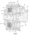
- FIG. 6 illustrates an alternative construction for the hydraulic coupling of the present invention; and
- FIG. 7 is a sectional view of a sealed version of the hydraulic coupling shown in FIG. 1 constructed according to another embodiment of the present invention.
-
- In general, the present invention is directed to a hydromechanical limited slip and torque transfer apparatus, hereinafter referred to as a hydraulic coupling. Driveline applications contemplated for the hydraulic couplings of the present invention include, but are not limited to, limited slip axle differentials, power take-offs and in-line couplings for use in all-wheel drive vehicles, on-demand couplings and limited slip differentials in use in four-wheel drive transfer cases, limited slip differentials for use in transaxles, and any other type of driveline apparatus requiring drive torque to be transferred between two rotary members. Furthermore, the hydraulic coupling of the present invention find particular application in vehicle driveline apparatuses which are not equipped with secondary lube pumping systems. Accordingly, this invention solves a problem inherent to conventional hydraulic couplings by providing a fluid distribution system and control valving which permit a hydraulic pump to supply fluid from a supply chamber to a piston chamber for actuating a clutch assembly and to a clutch chamber for cooling and lubricating the clutch assembly.
- Referring initially to FIG. 1, a hydraulic coupling according to the present invention is generally identified with
reference numeral 10.Hydraulic coupling 10 is installed within adriveline apparatus 11 and is operatively coupled between a first rotary member and a second rotary member for limiting speed differentiation and/or transferring rotary power (drive torque) therebetween. In the embodiment shown, first rotary member is a primary or drivenshaft 14 and second rotary member is a secondary ornon-driven shaft 12 which is supported by bearing 16 for rotation relative to drivenshaft 14. As will become apparent below,hydraulic coupling 10 is adapted to automatically and progressively coupleshafts shaft 14 toshaft 12 it is understood that, in other applications,shaft 12 could be the driven rotary member. - In general,
hydraulic coupling 10 includes apump assembly 18 and atransfer clutch 20 that are operably arranged within acover assembly 22. According to the embodiment shown,pump assembly 18 includes a bi-directionalhydraulic pump 24 and apiston assembly 46 whiletransfer clutch 20 is a hydraulically-actuated multi-plate clutch assembly.Cover assembly 22 includes a cylindricalouter drum 26 and a pair of coverplates 28a nd 30 secured (i.e., welded) thereto.Cover plate 28 is shown fixed (i.e., splined) toshaft 12 such thatcover assembly 22 drives or is driven byshaft 12. Likewise, atubular pump shaft 14a is splined toshaft 14 and is shown to support an O-ring seal 34 for permittingcover plate 30 ofcover assembly 22 to rotate relative topump shaft 14a while providing a fluid-tight seal therebetween. As such,cover assembly 22 surroundssecond shaft 14 and defines anannular drum chamber 35 therewith. A pair ofinlets 36 are formed throughcover plate 30 for permitting hydraulic fluid to be drawn intohydraulic coupling 10 from a sump, schematically identified byblock 32, located withindrivetrain apparatus 11. - With continued reference to FIG. 1,
transfer clutch 20 is shown located withindrum chamber 35 and includes aclutch hub 38 fixed (i.e., splined) to shaft 14 (orpump shaft 14a), and amulti-plate clutch pack 40.Clutch pack 40 includes a plurality ofinner clutch plates 42 fixed (i.e., splined) toclutch hub 38 and which are alternately interleaved with a plurality ofouter clutch plates 44 fixed (i.e., splined) toouter drum 26. Alternatively,clutch hub 38 may be eliminated withinner clutch plates 42 splined directly to one ofshafts assembly 46 includes apiston housing 48 that is fixed (i.e., splined) at its outer periphery toouter drum 26, and apiston 50 that is retained for sliding movement in anannular piston chamber 52 formed inpiston housing 48. As shown, an O-ring seal 54 is retained in a groove formed inpump shaft 14a for permittingpiston housing 48 to rotate relative topump shaft 14a while providing a fluid-tight seal therebetween. As such,piston assembly 46 cooperates withcover assembly 22 to define aclutch chamber 56. In addition, O-ring seals piston chamber 52 andpiston 50. Thus,piston 50 is supported for axial sliding movement withinpiston chamber 52 relative to interleavedmulti-plate clutch pack 40 for applying a compressive clutch engagement force thereon, thereby transferring drive torque from drivenshaft 14 to non-drivenshaft 12. Alternatively,piston 50 may have a cover material bonded thereto, such as rubber, to provide a sealed sliding engagement with the inner and outer edge surfaces ofpiston chamber 52. The amount of torque transfer betweenshafts piston 50 onclutch pack 40 which, in turn, is a function of the fluid pressure withinpiston chamber 52. Moreover, the magnitude of the fluid pressure withinpiston chamber 52 is controlled as a function of the speed differential (ΔRPM) betweens hafts 12 and 14. - With particular reference now to FIGS. 1 through 3,
piston housing 48 is shown to have a fluid distribution and valving arrangement that is operable for selectively controlling the delivery of fluid topiston chamber 52 andclutch chamber 56 fromhydraulic pump 24. In particular,piston housing 48 includes a pair offirst transfer ports 60 each extending between and communicating with one of a pair offirst shadow slots 62 and an arcuatepiston inlet slot 64 formed inpiston chamber 52. Acheck valve 66 is mounted byrivets 68 inpiston inlet slot 64 and its opposite terminal ends overliefirst transfer ports 60. Preferably,check valve 66 is an elongated metallic reed valve element. Based on the direction of relative rotation betweenshafts 12 and 14 (which results in a corresponding directional rotation of hydraulic pump 24), the hydraulic pressure in one offirst shadow slots 62 generated by the pumping action ofhydraulic pump 24 causes the corresponding terminal end ofcheck valve 66 to resiliently deflect to an "open" position away frompiston inlet slot 64 inpiston housing 48, thereby opening its correspondingfirst transfer port 60 to permit fluId to flow from that particularfirst shadow slot 62 intopiston chamber 52. Concurrently, the lower fluid pressure in the other offirst shadow slots 62 is unable to move the other terminal end ofcheck valve 66 which is maintained in a "closed" position withinpiston inlet slot 64 for inhibiting the discharge of hydraulic fluid frompiston chamber 52 through the other offirst transfer ports 60. As such, the hydraulic fluid inpiston chamber 52, if it exceeds a predetermined minimum pressure, will actuate transfer clutch 20 by movingpiston 50 toward the clutch pack for applying the resultant clutch engagement force thereon. During the opposite direction of relative rotation betweenshafts check valve 66 are reversed for eachfirst transfer port 60. Upon cessation of the pumping action, each terminal end ofcheck valve 66 is biased to return to its respective closed position for maintaining a supply of fluid inpiston chamber 52. Thus,check valve 66 functions as a normally-closed valve. As will be appreciated,a separate reed-type check valve could be used with eachfirst transfer port 60 and/or any other suitable type of check valve could be used to control flow intopiston chamber 52 fromhydraulic pump 24. - As seen from FIGS. 2 and 3,
piston housing 48 also includes a pair ofsecond transfer ports 74 each of which communicate with one of a pair ofsecond shadow slots 76 and anannular discharge cavity 78 which communicates withclutch chamber 56. The valving arrangement associated withpiston housing 48 further includes acheck valve 80 mounted byrivets 82 indischarge cavity 78. As is similar tocheck valve 66,check valve 80 is preferably an elongated metallic reed valve element. Based on the direction of relative rotation betweenshafts second shadow slots 76 generated by the pumping action ofhydraulic pump 24 will cause the corresponding terminal end ofcheck valve 80 to resiliently deflect to an "open" position away frompiston housing 48, thereby opening its correspondingsecond transfer port 74 to permit the flow of pumped hydraulic fluid intodischarge cavity 78 andclutch chamber 56. Concurrently, the other terminal end ofcheck valve 80 is maintained in a "closed" position relative topiston housing 48 for inhibiting the flow of hydraulic fluid fromclutch chamber 56 through the othersecond transfer port 74. Upon cessation of the pumping action, each terminal end ofcheck valve 80 is biased to return to its respective closed position. As before, a separate reed-type check valve can be used with eachsecond transfer port 74 and any other type of suitable check valve can be used. - As best seen from FIG. 3,
first shadow slots 62 andsecond shadow slots 76 are symmetrical about line "A". In addition, aweb portion 82 separates eachfirst shadow slot 62 from a correspondingsecond shadow slot 76. As such, fluid can be delivered fromsecond shadow slots 76 throughsecond transfer ports 74 to dischargecavity 78 without affecting the fluid pressure delivered throughfirst transfer ports 60 topiston chamber 52. Thus, the pressurization characteristics forpiston chamber 52 can be tuned for controlling movement ofpiston 50 and actuation of transfer clutch 20 in a manner which is independent of the pumped fluid used to lubricate and coolclutch pack 40 inclutch chamber 56. In this manner, the fluid pressure delivered topiston chamber 52 is higher than the fluid pressure delivered toclutch chamber 56 since the fluid inclutch chamber 56 is not intended to actuatetransfer clutch 20. Optionally,second shadow slot 76 could be used for delivery of high pressure fluid to piston chamber andfirst shadow slot 62 could be used for delivery of low pressure fluid toclutch chamber 56. Moreover, the relative size oftransfer ports -
Hydraulic coupling 10 Includes a control valve arrangement which is operable for setting the predetermined minimum pressure level withinpiston chamber 52 at which transfer clutch 20 is initially actuated to transfer drive torque and which is further operable to compensate for viscosity changes in the hydraulic fluid. As shown in FIG. 2, a pair ofcontrol valves 86 are secured byrivets 88 inchamfered bleed slots 90 formed inpiston chamber 52 such that the terminal end of eachcontrol valve 86 is normally maintained in an "open" position displaced from ableed port 92. Bleedports 92 extend throughpiston housing 48 and provide fluid communication betweenfirst transfer ports 60 and bleedslots 90. During initial relative rotation, the pumping action ofhydraulic pump 24 causes fluid to be supplied topiston chamber 52 through one ofbleed ports 92 from its correspondingfirst shadow slot 62 on the discharge side ofhydraulic pump 24. Concurrently, fluid is discharged frompiston chamber 52 through theother bleed port 92 to its correspondingfirst shadow slot 62 on the suction side ofhydraulic pump 24. As an alternative arrangement, a bleed port can be formed throughpiston 50 with acontrol valve 86 arranged for controlling flow frompiston chamber 52 intoclutch chamber 56. -
Control valves 86 are preferably bi-metallic valve elements made of a laminated pair of dissimilar metallic strips having different coefficients of thermal expansion. As such, the terminal end of eachcontrol valve 86 moves relative to itscorresponding bleed port 92 as the fluid temperature varies for controlling fluid flow throughbleed ports 92 regardless of changes in the viscosity of hydraulic fluid caused by temperature changes. However, when the ΔRPM exceeds a predetermined actuation value, the fluid inpiston chamber 52 reaches its predetermined pressure level and causes the terminal end ofcontrol valve 86 on the suction side ofpump 24 to move to its "closed" position for inhibiting fluid flow through itscorresponding bleed port 92. This flow restriction causes an increase in fluid pressure withinpiston chamber 52 which, in turn, causespiston 50 to exert a large clutch engagement force onclutch pack 40 for actuatingtransfer clutch 20. A by-pass groove 94 is shown formed in the terminal end of eachcontrol valve 86 to permit a small amount of bleed flow out ofpiston chamber 52 even whencontrol valve 86 is in its closed position to gradually depressurizepiston chamber 52 and disengage transfer clutch 20 whenpump 24 is inactive. As an alternative, the bleed groove can be formed inbleed slot 90 and communicate withbleed port 92. - As noted,
hydraulic pump 24 is operable for pumping hydraulic fluid throughfirst transfer ports 60 intopiston chamber 52 to actuate transfer clutch 20 and for pumping hydraulic fluid throughsecond transfer ports 74 intoclutch chamber 56 for cooling and lubricatingclutch pack 40. Preferably,hydraulic pump 24 is a bi-directional rotary pump capable of pumping fluid at a rate proportional to the speed differential betweenshafts hydraulic pump 24 includes agerotor pump assembly 100 and apump housing 102 which are both located withindrum chamber 35. Referring to FIGS. 1 and 4,gerotor pump assembly 100 is shown as a three component arrangement including apump ring 104 that is fixed (i.e., keyed or splined) to pumpshaft 14a, aneccentric ring 106 that is fixed (i.e., splined) toouter drum 26, and astator ring 108 that is operably disposed therebetween.Pump ring 104 has a plurality ofexternal teeth 110 that rotate concentrically relative to pumpshaft 14a about a common rotational axis, as noted by axis line "X".Stator ring 108 includes a plurality ofinternal lobes 112 and has an outercircumferential edge surface 114 that is journally rotatably supported within a circularinternal bore 116 formed ineccentric ring 106. Internal bore 116 is offset from the rotational axis "X" such that, due to meshing ofinternal lobes 112 ofstator ring 108 withexternal teeth 110 ofpump ring 104, relative rotation betweenpump ring 104 andeccentric ring 106 causes eccentric rotation ofstator ring 108. This eccentric arrangement results in pumping action of fluid under pressure frompump inlet slots 116 formed inpump housing 102 on the inlet side ofhydraulic pump 24 to corresponding first andsecond shadow slots piston housing 48 adjacent the discharge side ofpump 24. Preferably,stator ring 108 has a number oflobes 112 that is one more than the number ofteeth 110 provided onpump ring 104. As an alternative,hydraulic pump 24 can be a gear pump or any other fluid pump operable for generating hydraulic pressure in response to relative rotation between two pump components. -
Gerotor pump assembly 100 is shown operably installed withindrum chamber 35 betweenpiston housing 48 and pumphousing 102.Pump housing 102 is shown to have its outer peripheral surface fixed (i.e., splined) for rotation withouter drum 26 while its inner peripheral surface is journally supported for relative rotation with respect to pumpshaft 14a and is sealed relative thereto by an O-ring seal 120.Cover plate 30 is formed to include anannular supply chamber 122 which communicates withinlets 36.Pump housing 102 includes a series offirst inlet ports 124a extending betweenfirst inlet slots 116a andsupply chamber 122.Pump housing 102 also includes a series ofsecond inlet ports 124b extending betweensecond inlet slots 116b andsupply chamber 122. Whenhydraulic pump 24 is assembled,first inlet slots 116a are aligned withfirst shadow slots 62 andsecond inlet slots 116b are aligned withsecond shadow slots 76. A valving arrangement controls the delivery of fluid fromsupply chamber 122 into first andsecond inlet slots second check valves 126and 126b respectively mounted byrivets 128 within first andsecond inlet slots inlet ports valves rivets 128 from a "closed" position to an "open" position in response to the directional pumping action ofhydraulic pump 24 such that hydraulic fluid withinsupply chamber 122 is drawn into a corresponding set ofinlet ports check valve inlet slots cover plate 30 can be eliminated withpump housing 102 welded toouter drum 26 such thatinlet ports sump 32.Hydraulic coupling 10 further includes a fluid flow path for returning fluid fromclutch chamber 56 tosump 32. This fluid flow path is defined in part bylubrication ports outer drum 26 andcover plate 28. - Referring now to FIG. 6, an alternative embodiment of
hydraulic coupling 10 is shown and identified byreference numeral 10A. Common reference numerals are used to identify similar elements with the following description limited primarily to the differences betweenhydraulic couplings hydraulic coupling 10A is shown withpump shaft 14a eliminated such thatcover plates cover assembly 22 are rotatably supported thereon bybearings 130 and sealed relative thereto bysuitable seals 132.Cover plate 28 includes threadedbores 134 that are adapted to accept threaded fasteners for fixing a rotary component (i.e., a yoke, a sprocket, a ring gear, etc.) to coverassembly 22.Transfer clutch 20 is also shown withclutch hub 38 eliminated such thatinner plates 42 are splined directly toshaft 14. Furthermore, the upper half of FIG. 6 showsshaft 14 to include ayoke 136 with threadedapertures 138 for receipt of threaded fasteners to secureshaft 14 to another shaft or, other types of rotary members and/or joints. A slightly modified version ofhydraulic coupling 10A is shown in the lower half of FIG. 6 whereinshaft 14 includesexternal spines 140 for connection to internal splines of another driveline component. - Referring now to FIG. 7, a self-contained or "sealed" hydraulic coupling 10B is shown. Since hydraulic coupling 10B is sealed relative to
driveline apparatus 11, it does not require fluid to be drawn fromsump 32 and, as such, includes an internal recirculatory flow path for returning fluid inpiston chamber 52 andclutch chamber 56 to supplychamber 122. In most aspects, the construction of hydraulic coupling 10B is similar to that ofhydraulic coupling 10 of FIG. 1 with the exceptions that lubricationports cover assembly 22 have been eliminated to sealclutch chamber 56 relative tosump 32, aplug 150 has been mounted ininlet 36 to sealsupply chamber 122 relative tosump 32, and seals 152 and 154 have been added to assist in preventing the fluid within hydraulic coupling 10B from leaking intosump 32 ofdriveline apparatus 11. Due to the sealed arrangement, the type of fluid used within hydraulic coupling 10B can be different from that used withindriveline apparatus 11. - To provide means for returning fluid in hydraulic coupling 10B from
clutch chamber 56 to supplychamber 122, a return flow path is provided by eliminating one or more of the longitudinal internal spine teeth onouter drum 26. As such, fluid withinclutch chamber 56 travels along the channel(s) formed by the missing spline teeth past the outer periphery ofpiston housing 48,eccentric ring 106, and pumphousing 102. One or more recessednotches 155 are formed inpump housing 102 to permit fluid in the channel(s) to flow intosupply chamber 122. Likewise, to provide means for returning fluid in hydraulic coupling 10B frompiston chamber 50 to supplychamber 122, a bleed flow path is provided by a series of alignedthroughbores pump housing 48,eccentric ring 106, and pumphousing 102. Aflow control valve 162 is mounted in one ofthroughbores - Thus, the present invention is directed to providing both sealed and unsealed construction for a hydraulic coupling equipped with a clutch assembly, a hydraulic pump and a fluid distribution system for delivering fluid from the hydraulic pump to a first flow path for actuating the clutch assembly and to a second flow path for cooling the clutch assembly. The Invention being thus described, it will be obvious that the same may be varied in many ways. Such variations are not to be regarded as a departure from the spirit and scope of the invention, and all such modifications as would be obvious to one skilled in the art are intended to be included within the scope of the following claims.
Claims (12)
- A hydraulic coupling for use in a motor vehicle driveline apparatus to rotatively couple first and second rotary members, the hydraulic coupling comprising:a cover assembly fixed for rotation with the first rotary member and surrounding the second rotary member to define a drum chamber;a transfer clutch located in said drum chamber and including a clutch pack having a first clutch plate fixed for rotation with said cover assembly and a second clutch plate fixed for rotation with the second rotary member;a piston housing located in said drum chamber and defining a piston chamber, a first transfer port in fluid communication with said piston chamber, and a second transfer port in fluid communication with said clutch pack;a piston disposed in said piston chamber for movement relative to said clutch pack for exerting a clutch engagement force thereon the magnitude of which is a function of the fluid pressure in said piston chamber; anda hydraulic pump located in said drum chamber and operative for delivering fluid to said first and second transfer ports in response to a speed differential between the first and second rotary members.
- The hydraulic coupling of claim 1, wherein said piston housing is positioned between said clutch pack and said hydraulic pump and includes a first slot communicating with said first transfer port and a second slot communicating with said second transfer port, said hydraulic pump operable to deliver fluid to said first and second slots in response to speed differentiation between the first and second rotary members.
- The hydraulic coupling of claim 1 or claim 2, wherein said clutch pack is retained in a clutch chamber formed within said cover assembly, and wherein said piston housing is disposed in said cover assembly between said hydraulic pump and said clutch chamber.
- A hydraulic coupling for rotatively coupling a first shaft and a second shaft, comprising:a cover assembly coupled for rotation with the first shaft;a piston housing located between said cover assembly and the second shaft, said piston housing defining a piston chamber, a first transfer port in fluid communication with said piston chamber, a clutch chamber, and a second transfer port in fluid communication with said clutch chamber;a transfer clutch disposed in said clutch chamber and operatively connected between said cover assembly and the second shaft;a piston disposed in said piston chamber for movement relative to said transfer clutch for exerting a clutch engagement force thereon the magnitude of which is a function of the fluid pressure in said piston chamber; anda hydraulic pump including a first pump component coupled for rotation with said cover assembly and a second pump component coupled for rotation with the second shaft, said hydraulic pump operative for pumping fluid into said first and second transfer ports in response to speed differentiation between said first and second pump components.
- The hydraulic coupling of claim 4, wherein said piston housing is positioned between said transfer clutch and said hydraulic pump and further includes a first slot communicating with said first transfer port and a second slot communicating with said second transfer port, and said hydraulic pump is operable for delivering fluid to said first and second slots.
- The hydraulic coupling of claim 4 or claim 5, wherein said cover assembly includes an outer drum, a first cover plate secured to said outer drum and fixed to the first shaft, and a second cover plate fixed to said outer drum and sealed relative to the second shaft, said hydraulic coupling further including a check valve for permitting fluid to flow from a sump into a supply chamber through a port in said second cover plate while preventing flow from said supply chamber into said sump.
- A hydraulic coupling for use in a driveline apparatus having a casing containing hydraulic fluid to rotatively couple first and second rotary members, the hydraulic coupling comprising:a transfer clutch disposed in a clutch chamber and operatively connected between the first and second rotary members;a piston housing defining a piston chamber;a piston disposed in said piston chamber and actuatable to engage said transfer clutch and rotatively couple the first and second rotary members;a hydraulic pump for providing a pumping action in response to relative rotation between the first and second rotary members;a first flow path for supplying hydraulic fluid from a sump in the casing to said hydraulic pump;a second flow path for supplying hydraulic fluid from said hydraulic pump to said piston chamber; anda third flow path for supplying hydraulic fluid from said hydraulic pump to said clutch chamber.
- The hydraulic coupling of claim 7, wherein said second flow path includes a first transfer port formed through said piston housing and said third flow path includes a second transfer port formed through said piston housing.
- The hydraulic coupling of claim 8, wherein said piston housing is positioned between said transfer clutch and said hydraulic pump, and said second flow path further includes a first slot formed in said piston housing which communicates with said first transfer port, and said third flow path further includes a second slot formed in said piston housing which communicates with said second transfer port, and wherein said hydraulic pump is operable for supplying hydraulic fluid to said first and second slots.
- The hydraulic coupling of any one of claims 3, 5 and 9, further comprising:a first check valve moveable between an open position and a closed position relative to said first transfer port and permitting fluid to flow from said first slot into said piston chamber while preventing fluid flow from said piston chamber into said first slot; anda second check valve moveable between an open position and a closed position relative to said second transfer port for permitting fluid to flow from said second slot into said clutch chamber while preventing fluid flow from said clutch chamber into said second slot.
- The hydraulic coupling of claim 10, wherein said first and second check valves are mounted to said piston housing for movement relative thereto.
- The hydraulic coupling of any one of claims 3, 4 and 7 wherein said clutch chamber is sealed such that fluid in said clutch chamber is transferred through a flow passage to a supply chamber provided at an inlet to said hydraulic pump.
Applications Claiming Priority (6)
| Application Number | Priority Date | Filing Date | Title |
|---|---|---|---|
| US6981197P | 1997-12-17 | 1997-12-17 | |
| US6995197P | 1997-12-17 | 1997-12-17 | |
| US69811P | 1997-12-17 | ||
| US69951P | 1997-12-17 | ||
| US189884 | 1998-11-11 | ||
| US09/189,884 US6041903A (en) | 1997-12-17 | 1998-11-11 | Hydraulic coupling for vehicular power transfer systems |
Publications (3)
| Publication Number | Publication Date |
|---|---|
| EP0926378A2 true EP0926378A2 (en) | 1999-06-30 |
| EP0926378A3 EP0926378A3 (en) | 2000-05-24 |
| EP0926378B1 EP0926378B1 (en) | 2006-04-26 |
Family
ID=27371605
Family Applications (1)
| Application Number | Title | Priority Date | Filing Date |
|---|---|---|---|
| EP98310301A Expired - Lifetime EP0926378B1 (en) | 1997-12-17 | 1998-12-16 | Hydraulic coupling for vehicular power transfer systems |
Country Status (4)
| Country | Link |
|---|---|
| US (1) | US6041903A (en) |
| EP (1) | EP0926378B1 (en) |
| CA (1) | CA2256155C (en) |
| DE (1) | DE69834308T2 (en) |
Cited By (5)
| Publication number | Priority date | Publication date | Assignee | Title |
|---|---|---|---|---|
| WO2001027487A1 (en) * | 1999-10-12 | 2001-04-19 | Steyr Daimler Puch Fahrzeugtechnik Ag & Co. Kg | Rotational speed differential hydraulic clutch having control valves |
| DE10017131A1 (en) * | 2000-04-06 | 2001-10-18 | Gkn Viscodrive Gmbh | Axial adjustment device |
| DE102005021945B3 (en) * | 2005-05-12 | 2007-02-01 | Gkn Driveline International Gmbh | Automatic hydrostatic locking clutch used in drive train of vehicle, includes nested rotors on adjacent parallel axes containing magneto-rheological fluid with externally-controllable viscosity |
| DE102004033439C5 (en) * | 2004-07-08 | 2009-02-26 | Getrag Driveline Systems Gmbh | Powertrain for a motor vehicle |
| EP3096035A1 (en) * | 2015-05-19 | 2016-11-23 | Goodrich Corporation | Clutch including a pump |
Families Citing this family (23)
| Publication number | Priority date | Publication date | Assignee | Title |
|---|---|---|---|---|
| DE19860532C2 (en) * | 1998-12-30 | 2001-02-01 | Gkn Viscodrive Gmbh | Differential speed controlled transmission clutch |
| AT3343U1 (en) * | 1999-01-26 | 2000-01-25 | Steyr Daimler Puch Ag | SPEED DIFFERENTIAL-RELATED HYDRAULIC CLUTCH WITH TEMPERATURE COMPENSATION |
| CA2276643A1 (en) * | 1999-06-23 | 2000-12-23 | Bombardier Inc. | Straddle-type all-terrain vehicle with progressive differential |
| US6305515B1 (en) * | 1999-07-20 | 2001-10-23 | Power Transmission Technology, Inc. | Hydraulically actuated power takeoff clutch assembly |
| ATE289014T1 (en) * | 1999-12-07 | 2005-02-15 | Magna Drivetrain Ag & Co Kg | POWER TRANSMISSION UNIT WITH SPEED-DEPENDENT HYDRAULIC CLUTCH AND CENTRIFUGAL FORCE COMPENSATION |
| US6238315B1 (en) * | 1999-12-16 | 2001-05-29 | David Marshall Morse | Hydraulic coupling for vehicle drivetrain |
| US6315097B1 (en) | 2000-03-29 | 2001-11-13 | New Venture Gear, Inc. | Hydromechanical coupling with adaptive clutch control |
| US6446774B2 (en) | 2000-04-10 | 2002-09-10 | New Venture Gear, Inc. | Active control of a hydra-mechanical traction control device |
| US6953411B2 (en) * | 2001-04-02 | 2005-10-11 | Magna Drivetrain Of America, Inc. | Electronically-tuned hydromechanical coupling |
| US6626787B2 (en) * | 2001-04-02 | 2003-09-30 | New Venture Gear, Inc. | On-demand all-wheel drive system |
| US6942055B2 (en) | 2001-04-05 | 2005-09-13 | Magna Drivetrain Of America, Inc. | Electronically-controlled rear module for all-wheel drive system |
| US6578654B2 (en) | 2001-04-05 | 2003-06-17 | New Venture Gear, Inc. | Electronically-controlled coupling for all-wheel drive system |
| US6676555B2 (en) | 2001-12-14 | 2004-01-13 | Visteon Global Technologies, Inc. | Cone friction clutch |
| US6971494B2 (en) * | 2004-01-13 | 2005-12-06 | Magna Drivetrain Of America, Inc. | Torque transfer coupling with friction clutch and hydraulic clutch actuator |
| US7063198B2 (en) * | 2004-10-13 | 2006-06-20 | Eaton Corporation | Coupling device and improved fluid pressure system therefor |
| US7175013B2 (en) * | 2004-12-21 | 2007-02-13 | Magna Powertrain Usa, Inc. | On-demand cooling control for power transfer system |
| US7353928B2 (en) * | 2005-09-30 | 2008-04-08 | Dana Automotive Systems Group, Llc. | Torque coupling assembly with venting passage |
| DE102007038156A1 (en) * | 2007-08-13 | 2009-02-19 | Magna Powertrain Ag & Co Kg | clutch assembly |
| EP2655110B1 (en) * | 2010-12-23 | 2017-11-15 | Magna Powertrain of America, Inc. | Controlled gerotor actuated pre-trans parallel hybrid |
| US9156310B2 (en) * | 2013-01-11 | 2015-10-13 | Siemens Industry, Inc | Controlled lubricant volume seal housing |
| DE102014015809A1 (en) | 2014-10-24 | 2016-04-28 | Man Truck & Bus Ag | Hydraulic wheel drive for a motor vehicle and method for its operation |
| US10583734B2 (en) * | 2017-05-04 | 2020-03-10 | Borgwarner Inc. | Tubeless lubrication delivery system for a compact transfer case |
| US11920664B2 (en) | 2022-06-30 | 2024-03-05 | Bombardier Recreational Products Inc. | Limited-slip differential system |
Citations (5)
| Publication number | Priority date | Publication date | Assignee | Title |
|---|---|---|---|---|
| US5148900A (en) | 1991-06-25 | 1992-09-22 | New Venture Gear, Inc. | Viscous coupling apparatus with coined plates and method of making the same |
| US5358454A (en) | 1993-06-11 | 1994-10-25 | New Venture Gear, Inc. | Temperature and pressure compensated geared traction unit |
| US5649459A (en) | 1994-09-21 | 1997-07-22 | Nissan Motor Co., Ltd. | Power transfer system for vehicle |
| US5704863A (en) | 1996-07-01 | 1998-01-06 | New Venture Gear, Inc. | Two-speed transfer case with on-demand torque control having a coupling pump and a supply pump |
| US5779013A (en) | 1996-07-18 | 1998-07-14 | New Venture Gear, Inc. | Torque transfer apparatus using magnetorheological fluids |
Family Cites Families (8)
| Publication number | Priority date | Publication date | Assignee | Title |
|---|---|---|---|---|
| US5310388A (en) * | 1993-02-10 | 1994-05-10 | Asha Corporation | Vehicle drivetrain hydraulic coupling |
| US5536215A (en) * | 1993-02-10 | 1996-07-16 | Asha Corporation | Hydraulic coupling for vehicle drivetrain |
| US5595214A (en) * | 1993-02-10 | 1997-01-21 | Asha Corporation | Hydraulic coupling for vehicle drivetrain |
| US5749801A (en) * | 1995-03-28 | 1998-05-12 | Tochigi Fuji Sangyo Kabushiki Kaisha | Differential unit |
| US5611746A (en) * | 1995-06-28 | 1997-03-18 | Asha Corporation | Vehicle drivetrain coupling |
| US5702319A (en) * | 1995-10-13 | 1997-12-30 | Dana Corporation | Hydromechanical system for limiting differential speed between differentially rotating members |
| DE19619891C2 (en) * | 1996-05-17 | 2001-07-26 | Gkn Viscodrive Gmbh | Device for controlling a clutch |
| US5827145A (en) * | 1997-03-17 | 1998-10-27 | Asha Corporation | Hydraulic coupling having supplemental actuation |
-
1998
- 1998-11-11 US US09/189,884 patent/US6041903A/en not_active Expired - Lifetime
- 1998-12-16 DE DE69834308T patent/DE69834308T2/en not_active Expired - Lifetime
- 1998-12-16 EP EP98310301A patent/EP0926378B1/en not_active Expired - Lifetime
- 1998-12-16 CA CA002256155A patent/CA2256155C/en not_active Expired - Fee Related
Patent Citations (5)
| Publication number | Priority date | Publication date | Assignee | Title |
|---|---|---|---|---|
| US5148900A (en) | 1991-06-25 | 1992-09-22 | New Venture Gear, Inc. | Viscous coupling apparatus with coined plates and method of making the same |
| US5358454A (en) | 1993-06-11 | 1994-10-25 | New Venture Gear, Inc. | Temperature and pressure compensated geared traction unit |
| US5649459A (en) | 1994-09-21 | 1997-07-22 | Nissan Motor Co., Ltd. | Power transfer system for vehicle |
| US5704863A (en) | 1996-07-01 | 1998-01-06 | New Venture Gear, Inc. | Two-speed transfer case with on-demand torque control having a coupling pump and a supply pump |
| US5779013A (en) | 1996-07-18 | 1998-07-14 | New Venture Gear, Inc. | Torque transfer apparatus using magnetorheological fluids |
Cited By (10)
| Publication number | Priority date | Publication date | Assignee | Title |
|---|---|---|---|---|
| WO2001027487A1 (en) * | 1999-10-12 | 2001-04-19 | Steyr Daimler Puch Fahrzeugtechnik Ag & Co. Kg | Rotational speed differential hydraulic clutch having control valves |
| US6484856B1 (en) | 1999-10-12 | 2002-11-26 | Steyr-Daimler-Puch Fahrzeugtechnik Ag & Co. Kg | Speed-difference-dependent hydraulic coupling with control valves |
| US6684991B1 (en) * | 1999-10-12 | 2004-02-03 | Steyr-Daimler-Puch Fahrzeugtechnik Ag & Co Kg | Rotational speed differential hydraulic clutch having control valves |
| DE10017131A1 (en) * | 2000-04-06 | 2001-10-18 | Gkn Viscodrive Gmbh | Axial adjustment device |
| DE10017131C2 (en) * | 2000-04-06 | 2002-02-21 | Gkn Viscodrive Gmbh | axial setting |
| US6581741B2 (en) | 2000-04-06 | 2003-06-24 | Gkn Viscodrive Gmbh | Axial setting device |
| DE102004033439C5 (en) * | 2004-07-08 | 2009-02-26 | Getrag Driveline Systems Gmbh | Powertrain for a motor vehicle |
| DE102005021945B3 (en) * | 2005-05-12 | 2007-02-01 | Gkn Driveline International Gmbh | Automatic hydrostatic locking clutch used in drive train of vehicle, includes nested rotors on adjacent parallel axes containing magneto-rheological fluid with externally-controllable viscosity |
| EP3096035A1 (en) * | 2015-05-19 | 2016-11-23 | Goodrich Corporation | Clutch including a pump |
| US10030714B2 (en) | 2015-05-19 | 2018-07-24 | Goodrich Corporation | Clutch including a pump |
Also Published As
| Publication number | Publication date |
|---|---|
| CA2256155C (en) | 2005-11-01 |
| CA2256155A1 (en) | 1999-06-17 |
| EP0926378B1 (en) | 2006-04-26 |
| EP0926378A3 (en) | 2000-05-24 |
| US6041903A (en) | 2000-03-28 |
| DE69834308T2 (en) | 2007-01-04 |
| DE69834308D1 (en) | 2006-06-01 |
Similar Documents
| Publication | Publication Date | Title |
|---|---|---|
| US6041903A (en) | Hydraulic coupling for vehicular power transfer systems | |
| US6095939A (en) | Differential for vehicular power transfer systems | |
| US6145644A (en) | Multi-function control valve for hydraulic coupling | |
| US6533095B2 (en) | Hydraulic coupling with multi-function control device | |
| EP1027545B1 (en) | Self-contained hydraulic coupling | |
| US6626787B2 (en) | On-demand all-wheel drive system | |
| US6112874A (en) | Hydromechanical coupling with torque-limiting and temperature-sensitive unloading features | |
| US6966396B2 (en) | Electronically-controlled rear drive module for all-wheel drive system | |
| US6953411B2 (en) | Electronically-tuned hydromechanical coupling | |
| US7878933B2 (en) | Hydraulic coupling with disconnect pump clutch | |
| CA2465280C (en) | Rear drive module for all-wheel drive vehicle | |
| US8763777B2 (en) | Hydraulic coupling | |
| US6688446B2 (en) | Rear drive module for all-wheel drive vehicle |
Legal Events
| Date | Code | Title | Description |
|---|---|---|---|
| PUAI | Public reference made under article 153(3) epc to a published international application that has entered the european phase |
Free format text: ORIGINAL CODE: 0009012 |
|
| AK | Designated contracting states |
Kind code of ref document: A2 Designated state(s): DE GB |
|
| AX | Request for extension of the european patent |
Free format text: AL;LT;LV;MK;RO;SI |
|
| PUAL | Search report despatched |
Free format text: ORIGINAL CODE: 0009013 |
|
| AK | Designated contracting states |
Kind code of ref document: A3 Designated state(s): AT BE CH CY DE DK ES FI FR GB GR IE IT LI LU MC NL PT SE |
|
| AX | Request for extension of the european patent |
Free format text: AL;LT;LV;MK;RO;SI |
|
| 17P | Request for examination filed |
Effective date: 20001027 |
|
| AKX | Designation fees paid |
Free format text: DE GB |
|
| 17Q | First examination report despatched |
Effective date: 20040325 |
|
| GRAP | Despatch of communication of intention to grant a patent |
Free format text: ORIGINAL CODE: EPIDOSNIGR1 |
|
| GRAS | Grant fee paid |
Free format text: ORIGINAL CODE: EPIDOSNIGR3 |
|
| GRAA | (expected) grant |
Free format text: ORIGINAL CODE: 0009210 |
|
| AK | Designated contracting states |
Kind code of ref document: B1 Designated state(s): DE GB |
|
| REG | Reference to a national code |
Ref country code: GB Ref legal event code: FG4D |
|
| REF | Corresponds to: |
Ref document number: 69834308 Country of ref document: DE Date of ref document: 20060601 Kind code of ref document: P |
|
| PLBE | No opposition filed within time limit |
Free format text: ORIGINAL CODE: 0009261 |
|
| STAA | Information on the status of an ep patent application or granted ep patent |
Free format text: STATUS: NO OPPOSITION FILED WITHIN TIME LIMIT |
|
| 26N | No opposition filed |
Effective date: 20070129 |
|
| PGFP | Annual fee paid to national office [announced via postgrant information from national office to epo] |
Ref country code: GB Payment date: 20141210 Year of fee payment: 17 |
|
| GBPC | Gb: european patent ceased through non-payment of renewal fee |
Effective date: 20151216 |
|
| PG25 | Lapsed in a contracting state [announced via postgrant information from national office to epo] |
Ref country code: GB Free format text: LAPSE BECAUSE OF NON-PAYMENT OF DUE FEES Effective date: 20151216 |
|
| PGFP | Annual fee paid to national office [announced via postgrant information from national office to epo] |
Ref country code: DE Payment date: 20161213 Year of fee payment: 19 |
|
| REG | Reference to a national code |
Ref country code: DE Ref legal event code: R119 Ref document number: 69834308 Country of ref document: DE |
|
| PG25 | Lapsed in a contracting state [announced via postgrant information from national office to epo] |
Ref country code: DE Free format text: LAPSE BECAUSE OF NON-PAYMENT OF DUE FEES Effective date: 20180703 |