EP0926875A1 - Access terminal with printer - Google Patents
Access terminal with printer Download PDFInfo
- Publication number
- EP0926875A1 EP0926875A1 EP98310575A EP98310575A EP0926875A1 EP 0926875 A1 EP0926875 A1 EP 0926875A1 EP 98310575 A EP98310575 A EP 98310575A EP 98310575 A EP98310575 A EP 98310575A EP 0926875 A1 EP0926875 A1 EP 0926875A1
- Authority
- EP
- European Patent Office
- Prior art keywords
- telephone
- information
- message
- user
- call
- Prior art date
- Legal status (The legal status is an assumption and is not a legal conclusion. Google has not performed a legal analysis and makes no representation as to the accuracy of the status listed.)
- Withdrawn
Links
Images


Classifications
-
- H—ELECTRICITY
- H04—ELECTRIC COMMUNICATION TECHNIQUE
- H04M—TELEPHONIC COMMUNICATION
- H04M1/00—Substation equipment, e.g. for use by subscribers
- H04M1/02—Constructional features of telephone sets
- H04M1/21—Combinations with auxiliary equipment, e.g. with clocks or memoranda pads
-
- H—ELECTRICITY
- H04—ELECTRIC COMMUNICATION TECHNIQUE
- H04M—TELEPHONIC COMMUNICATION
- H04M15/00—Arrangements for metering, time-control or time indication ; Metering, charging or billing arrangements for voice wireline or wireless communications, e.g. VoIP
- H04M15/28—Arrangements for metering, time-control or time indication ; Metering, charging or billing arrangements for voice wireline or wireless communications, e.g. VoIP with meter at substation or with calculation of charges at terminal
-
- H—ELECTRICITY
- H04—ELECTRIC COMMUNICATION TECHNIQUE
- H04M—TELEPHONIC COMMUNICATION
- H04M17/00—Prepayment of wireline communication systems, wireless communication systems or telephone systems
- H04M17/02—Coin-freed or check-freed systems, e.g. mobile- or card-operated phones, public telephones or booths
-
- H—ELECTRICITY
- H04—ELECTRIC COMMUNICATION TECHNIQUE
- H04M—TELEPHONIC COMMUNICATION
- H04M3/00—Automatic or semi-automatic exchanges
- H04M3/42—Systems providing special services or facilities to subscribers
- H04M3/487—Arrangements for providing information services, e.g. recorded voice services or time announcements
- H04M3/493—Interactive information services, e.g. directory enquiries ; Arrangements therefor, e.g. interactive voice response [IVR] systems or voice portals
- H04M3/4931—Directory assistance systems
-
- H—ELECTRICITY
- H04—ELECTRIC COMMUNICATION TECHNIQUE
- H04W—WIRELESS COMMUNICATION NETWORKS
- H04W4/00—Services specially adapted for wireless communication networks; Facilities therefor
- H04W4/24—Accounting or billing
-
- H—ELECTRICITY
- H04—ELECTRIC COMMUNICATION TECHNIQUE
- H04M—TELEPHONIC COMMUNICATION
- H04M1/00—Substation equipment, e.g. for use by subscribers
- H04M1/64—Automatic arrangements for answering calls; Automatic arrangements for recording messages for absent subscribers; Arrangements for recording conversations
Definitions
- This invention relates to a pay telephone with a printer which enables users to retrieve information from information service providers in graphical and printed form.
- Pay telephones currently exist with a conventional two-line vacuum florescent display for displaying information about telephone calls.
- the conventional two-line display is often used to display or scroll text which may be used for advertising to attract a user to the telephone.
- text-only information produces a rather uninteresting advertising format.
- telephone service providers such as the Talking Yellow Pages (tm) currently provide information in an audio format to users making requests of such services.
- Use of such services is valuable to only those who are satisfied in receiving data in an audio format.
- some of such information may be presented rather quickly and can be difficult to write down, for example, exchange rate information or directory assistance information.
- DA Directory Assistance
- the user is equipped with a pen or pencil and paper to make appropriate notes.
- some uses may record the information by means of a knife or other sharp object, thus causing damage to the telephone booth or worse.
- Other users will be forced to depend upon memory, which can result in the dialling of incorrectly remembered numbers and consequently, in unnecessary expenses.
- a method of providing information at a telephone includes the steps of establishing a telephone call to a telephone services provider, answering a telephone call at a telephone service provider in response to the telephone call made from the telephone, transmitting to the telephone services provider a request for information, receiving a request for the information from the telephone at the telephone services provider during the telephone call, transmitting an information message from the telephone services provider to the telephone in response to the request, where the information message is transmitted during the telephone call, receiving the information message at the telephone, and, producing a user-readable representation of the information at the telephone.
- the above problems are addressed by providing the user with a printed, hardcopy record containing the number provided by the DA service, the details of a call transaction, or of other information that may be appropriately submitted to or gathered by the telephone network, and subsequently delivered via the same means.
- the method includes the step of receiving a user-initiated request in response to user input received at the telephone.
- the method includes the step of receiving a request which includes the step of receiving DTMF signals from the telephone.
- the method includes the step of transmitting the information message in a pre-defined format including a message identifier and a representation of the information.
- the method includes the step of transmitting the information message in an FSK format.
- the method which includes the step of producing the user-readable representation includes the step of displaying the information on a graphical display at the telephone.
- the method includes the step of printing the information message on a printable medium.
- the method includes the step of reading the message identifier to determine the message type and executing a message handling routine associated with the message type.
- the method includes the step of loading into a print buffer print commands for controlling a printer.
- the method includes the step of receiving payment at the telephone for the use of the telephone services provider.
- the method includes the step of receiving payment authorization at the telephone for the use of the telephone services provider.
- the method includes the step of producing a call detail record relating to the telephone call.
- a system for providing information using a public switched telephone network includes a telephone services provider which includes an answering device for answering a telephone call, a request receiver for receiving a request for the information during the telephone call, and a transmitter for transmitting an information message in response to the request during the telephone call.
- the system further includes at least one telephone, which includes a user input device for receiving user input from a user of the telephone, a central office interface and a dialler for establishing a telephone call to the telephone services provider in response to user-input received at the user input device, a request message transmitter for transmitting to the telephone services provider a request for information, a message receiver for receiving the information message, and a user output device for providing a user-readable representation of the information message.
- a user input device for receiving user input from a user of the telephone
- a central office interface and a dialler for establishing a telephone call to the telephone services provider in response to user-input received at the user input device
- a request message transmitter for transmitting to the telephone services provider a request for information
- a message receiver for receiving the information message
- a user output device for providing a user-readable representation of the information message.
- the message receiver is operable to receive a user-initiated request in response to user input received at the telephone.
- the receiver includes a DTMF receiver for receiving DTMF signals from the telephone.
- the information message has a pre-defined format including a message identifier and a representation of the information.
- the transmitter includes an FSK transmitter for transmitting the information message in an FSK format.
- the user output device includes a graphical display for displaying the information.
- the user output device includes a printer for printing the user-readable representation on a printable medium.
- the system includes a processor programmed to read a message identifier in the information message to determine the message type and programmed to execute a message handling routine associated with the message type.
- the system includes a print buffer and the processor is programmed to load a print buffer for directing the printer to print the user-readable representation.
- the processor is programmed to produce print commands for directing the printer to produce a call detail record.
- the call detail record includes information relating a telephone call made with the telephone.
- the system includes a payment receiver for receiving payment at the telephone for the use of the telephone services provider.
- the system includes a payment authorization receiver for receiving payment authorization at the telephone for the use of the telephone services provider.
- a method of providing information at a telephone includes the steps of establishing a telephone call to a telephone services provider, transmitting to the telephone services provider a request for information, during the telephone call, receiving an information message in response to the request, where the information message being transmitted during the telephone call, and producing a user-readable representation of the information message at the telephone.
- the method includes the step of displaying the information message on a graphical display at the telephone.
- the method which includes the step of providing the user-readable representation includes the step of printing the user-readable representation on a printable medium.
- the method includes the step of reading a message identifier in the information message to determine the message type and executing a message handling routine associated with the message type.
- the method which includes the step of printing includes the step of loading into a print buffer print commands for controlling the printer.
- the method includes the step of producing a call detail record relating to the telephone call.
- the method includes the step of receiving payment at the telephone for the use of the telephone services provider.
- the method includes the step of receiving payment authorization at the telephone for the use of the telephone services provider.
- an apparatus for providing information at a telephone includes a central office interface and a dialler for establishing a telephone call to a telephone services provider, a request message transmitter for transmitting to the telephone services provider a request for the information, during the telephone call, an information receiver for receiving an information message in response to the request where the information message is received during the telephone call, and, an output device for providing a user-readable representation of the information message at the telephone.
- the output device includes a graphical display for displaying the user-readable representation.
- the output device includes a printer for printing the user-readable representation on a printable medium.
- the apparatus includes a processor programmed to read a message identifier in the information message to determine a message type and programmed to execute a message handling routine associated with the message type.
- the processor is programmed to produce print commands for directing the printer to print the information message.
- the processor is programmed to produce print commands for directing the printer to produce a call detail record.
- the call detail record includes call information relating a telephone call made with the telephone.
- the apparatus includes a payment receiver for receiving payment at the telephone for the use of the telephone services provider.
- the apparatus includes a payment authorization receiver for receiving payment authorization at the telephone for the use of the telephone services provider.
- a system for providing graphical content to a plurality of graphical display pay telephones is shown generally at 10 .
- a system for providing telephone information services by telephone, using a public switched telephone network is shown generally at 12 .
- the system 10 includes a telephone service provider which, in this embodiment, is a central payphone server 14 , a public switched telephone network (PSTN) 16 and a plurality of graphical display telephones shown generally at 18 . Both the central payphone server 14 and each of the plurality of telephones 18 is operable to communicate with each other via the public switched telephone network 16 .
- PSTN public switched telephone network
- the central payphone server 14 includes a processor 20 which is connected to memory shown generally at 22 structured to include a link table 24 , content files 26 including graphical files and rate tables.
- the processor is in communication with a call receiver 28 and a content file transmitter 30 .
- the call receiver 28 and the content file transmitter 30 are operable to receive and transmit PSK data over a subscriber loop 32 through a central office line interface 34 .
- the processor 20 is operable to receive from an external source, not shown, separate graphical content files 26 for each respective telephone of the plurality of telephones 18 .
- each telephone is associated with a corresponding set of graphical content files and rate table files.
- the processor uses the link table to establish correlations of graphical content files and rate table files with individual telephones of the plurality of telephones 18 .
- the call receiver 28 receives PSK signals from the central office line interface 34 , such PSK signals being interpreted as requests for specific content files from the memory 22 .
- the processor 20 retrieves a content file as determined from the link table 24 and transmits the content file using the content file transmitter 30 through the central office line interface 34 , as a phase shift keyed (PSK) information message.
- PSK message includes an identifier field 36 , an attribute field 38 and a data field 40 .
- the identifier field 36 identifies the message as a graphical or rate table message
- the attribute field 38 identifies certain attributes of graphical files such as time for display, effective date of display, etc.
- the data field in the case of graphical files includes a bit map file for controlling pixels on a display of the telephone which sent the PSK request message.
- the data field includes rate information associated with the requesting telephone.
- the public switched telephone network conveys the PSK message to the requesting telephone, telephone 42 for example.
- the telephone includes a processor 44 in communication with an input/output (I/O) interface 46 , Random Access Memory (RAM) 48 , and flash memory 52 .
- the I/O interface 46 is in communication with a central office line interface shown generally at 54 , a keypad soft key interpreter 56 , a display 58 , a printer 60 , a payment receiver 62 , a handset 64 , and a clock timer 66 .
- the I/O interface 46 has a modem hookswitch output 80 , a Receive Data (RXD) input 81 , a Transmit Data (TXD) output 83 , a voice path hookswitch output 78 , a DTMF output 82 , a handset offhook detect input 85 , an RX mute output 86 , an FSK input 88 a CAS input 92 , and an answer supervision signal input 95 .
- RXD Receive Data
- TXD Transmit Data
- the central office line interface 54 interfaces the I/O interface 46 with a central office line 55 .
- the central office line interface includes a PSK modem 93 and a PSK modem hookswitch 79 .
- the PSK modem hookswitch 79 is connected to tip and ring terminals 68 and 70 and is operable to connect the PSK modem 93 for communication through the central office line 55 .
- the PSK modem hookswitch 79 has a control input 81 connected to the modem hookswitch output 80 such that the I/O interface is operable to control the connection of the PSK modem 93 to the central office line 55 .
- the PSK modem has a receive signal output 84 and a transmit signal input 87 which are connected to the RXD input 81 and TXD output 83 respectively of the I/O interface to facilitate reception and transmission of data using the PSK modem 93 .
- the central office line interface 54 further includes a voice path hookswitch 74 , a 2 -wire to 4 -wire hybrid 72 , a DTMF transmitter 98 , an RX mute circuit 102 , a handset 64 , a handset offhook detector 65 , an FSK receiver 104 and a CAS detector 108 .
- the voice path hookswitch 74 is operable to connect the 2 -wire to 4 -wire hybrid 72 to the central office line.
- the voice path hookswitch 74 has a control input 76 which is connected to the voice path hookswitch output 78 which allows the processor to control the voice path hookswitch through the I/O interface 46 .
- the 2 -wire to 4 -wire hybrid has a voice transmit input 73 and a receive output 75 .
- the DTMF transmitter 98 receives signals from the DTMF output 82 which cause it to present DTMF tones to the transmit signal input 73 for transmission over the central office line 55 under control of the processor 44 .
- the handset 64 is also operable to produce voice transmit signals which are received at the input 73 , also for transmission over the central office line 55 .
- the receive output 75 is connected to the receive mute circuit 102 and the receive (RX) mute circuit has an output 103 which provides a receive signal to the handset 64 .
- the RX mute circuit is controlled by the RX mute output 86 of the I/O interface to selectively mute and unmute the receive path between the 2 -wire to 4 -wire hybrid and the handset 64 .
- the hybrid 72 includes an answer supervision circuit 71 which produces an active answer supervision signal to the answer supervision signal input 95 on the I/O interface 46 .
- the handset offhook detector 65 provides an active handset offhook detect signal to the handset offhook detect input 85 when the user lifts the handset 64 off of a cradle (not shown).
- the FSK receiver is connected to receive signals from the receive output 75 and to present data representing FSK transmissions so received to the FSK input 88 at the I/O interface 46 .
- the CAS detector 108 is connected to the 2 -wire to 4 -wire hybrid 72 to receive signals from the receive output 75 .
- the CAS detector 108 produces an active CAS detect signal which is applied to the CAS input 92 of the I/O interface.
- the CAS detect signal is rendered active when a caller alerting signal (CAS) is received from the central office.
- CAS caller alerting signal
- the keypad soft key interpreter 56 provides signals to the processor 44 indicative of keys pressed on a dial keypad of the telephone or on softkeys adjacent the display 58 .
- the keypad softkey interpreter 56 thus acts as a user input device for receiving user input from a user of the telephone.
- the display is a 3 inch by 4 inch pixel-addressabledisplay.
- the printer 60 is a small receipt type printer similar to that found on cash registers.
- the payment receiver 62 is a hybrid credit card and smart card receiver, in this embodiment, and includes credit card validation software and hardware, etc., and credit card reading apparatus for reading a credit or IC-based smart card. Effectively, the payment receiver 62 renders a payment signal active when a valid credit card (not shown) has been inserted into the credit card reader (not shown) and the credit card has been validated.
- the apparatus thus includes a payment authorization receiver for receiving payment authorization at the telephone for the use of the telephone services provider.
- the handset 64 is conventional and allows the user to send and receive voice signals in the usual manner over the central office line.
- the clock timer 66 provides time of day information, date information and timing information to the processor 44 .
- the RAM is configured to include a PSK receive buffer 110 , an FSK receive buffer 112 , a call detail record buffer 114 , a display buffer 115 and a pnnt buffer 117 .
- the PSK receive buffer includes an identification register 116 , an attribute register 118 , a plurality of data registers shown generally at 120 and a cyclic redundancy check register 122 .
- the PSK receive buffer is used to receive and store messages received at the PSK modem 93 shown in Figure 2 .
- the FSK receive buffer 112 includes a switch to application (STA) register 124 , a data link register 126 , an application name register 128 , an action code register 130 , a plurality of data registers shown generally at 132 and a CRC register 134 .
- the FSK receive buffer is used to receive and store messages received at the FSK receiver 104 shown in Figure 2 .
- the call detail record buffer 114 includes a called number register 136, a from register 140 , date and time registers 144 and 146 , a duration register 148 , a charge register 150 , a payment by register 152 and a rate register 154 .
- the call detail record buffer 114 is used to store call detail information compiled in response to a telephone call made from the pay telephone.
- the display buffer 115 is used to hold a bit map of a graphic image for presentation on the display 58 shown in Figure 2 .
- the print buffer 117 is used to assemble and hold print commands for driving the printer 60 to print a message or the like.
- the flash memory is configured to include a display file buffer 119 a program file buffer 121 and a rate table buffer 123 .
- the display file buffer 119 , program file buffer 121 and rate table buffer 123 are loaded from data accumulated from the data registers 132 in the FSK receive buffer shown in Figure 3 .
- the display files are loaded into the display buffer under the control of program files 121 .
- the program file buffer 121 is preloaded with program codes readable by the processor 44 for directing the processor to execute various routines for effecting various functions of the telephone.
- Such codes direct the processor to execute a flash update routine 156 , a user call routine 158 , a place call routine 160 , a content use routine 162 and conventional call control and display routines 164 .
- the flash update routine is shown generally at 156 and is run on a periodic basis, in this embodiment, once every 24 hours.
- the flash update routine begins with a first block 176 which directs the processor to determine whether or not the telephone is in use. This is done by determining the state of the voice path hookswitch output 78 , which is set to connect the telephone to the central office line 55 , according to the conventional call control routines when a user is using the telephone.
- the flash update routine continues to direct the processor to execute block 176 to continually determine whether or not the telephone is in use.
- block 178 directs the processor to set the voice path hookswitch output 78 active to connect the telephone to the central office line 55 .
- Block 180 then directs the processorto activate the DTMF output 82 to cause the DTMF transmitter 98 to transmit DTMF signals representing a telephone number of the central payphone server 14 shown in Figure 1 .
- block 182 then directs the processor to set the modem hookswitch output 80 active to close the modem hookswitch to connect the PSK modem to the central office line 55 .
- the voice path hookswitch output 78 is then set inactive to open the voice path hookswitch 74 to disconnect the DTMF transmitter 98 from the central office line 55 .
- the TXD output 83 is then activated with request data representing a request message.
- the PSK modem transmits a PSK request signal to the central payphone server 14 through the PSTN 16 .
- Block 184 then directs the processor to determine whether or not a PSK response has been received from the central payphone server within a predefined time period, t 2 , at the PSK modem 93 .
- PSK data is received at the PSK modem 93 and is stored in the PSK receive buffer 110 shown in Figure 3 such that identification information is stored in the identification buffer, attribute information is stored in the attribute register 118 , graphical data is stored in the data registers 120 and cyclic redundancy check (CRC) information is stored in the CRC register 122 .
- the processor calculates a CRC of its own on the contents of the identification register 116 , attribute register 118 and data registers 120 and compares the calculated CRC against the contents of the CRC register 122 . When the contents match, a PSK response is, for the purposes of block 184 , deemed to have occurred.
- block 186 directs the processor to set the modem hookswitch output 80 inactive thereby disconnecting the telephone from the central office line 55 and aborting the call.
- the flash update routine is, however, restarted at block 176 . Thus, the flash update routine persists until PSK response data is received.
- the processor is directed to block 188 which directs it to generate display files, program files or rate tables using the contents of the data registers 120 and to store such display files, program files or rate tables in corresponding buffers shown at 119 , 121 and 123 in Figure 4 .
- the display files are produced in a bit map format, so they can merely be copied directly into the display buffer 115 under the control of program files 121 .
- the display files control individual pixels on the display 58 according to conventional display routines.
- the program files are in a format readable by the processor 44 and are able to direct the processor to execute desired algorithms.
- the rate tables are in a format readable by the processor 44 and are used to determine a rate to be used for calculating charges for caller placed to various numbers.
- Block 192 then directs the processor to determine whether or not a valid payment signal has been received from the payment receiver 62 .
- the processor remains at block 192 until such valid payment signal is active and if such signal does not become active with a predefined time period, t 3 , block 194 directs the processor to load the display buffer 115 with a display file requesting the user to try again and the processor is directed to return to the conventional call control and display routines 164 .
- the processor is directed to block 196 where it waits for the user to place a call.
- the user is deemed to have placed a call when a valid telephone number has been dialled on the keypad soft key interpreter 56 .
- the conventional telephone routines provide a flag signal (not shown) indicating whether or not the user has properly entered a valid telephone number.
- block 198 directs the processor to load the display buffer with a display file from the display file buffer 119 , indicating that a call has not been properly placed and the processor is directed to return to the conventional call control and display routines.
- the processor is directed to block 199 which directs the processor to search the rate table buffer 123 for a rate table entry applicable to the number dialled by the user.
- the processor is directed to block 200 which directs it to send it a rate request to the central payphone server 14 .
- This rate request is made by directing the processor to execute the flash update routine shown in Figure 6 whereupon the PSK request transmitted at block 182 is a request for rate information. It will be recalled that after executing the flash update routine, the PSK receive buffer is loaded with data, in this instance, representing rate table information.
- the processor upon completion of the flash Update Routine called from the user call routine, the processor is directed to block 195 which directs it to store the appropriate rate data for the call, as found in the located rate table, in the rate register 154 .
- the processor is directed to load the called number register 136 with the number dialled by the user.
- the telephone number of the pay telephone used by the user is stored in the "from" register 140 .
- the processor is also directed to load an indication of the type of payment (eg. coin, smart card, credit card) and account number, if applicable, into the "payment by" register 152 .
- the processor is then directed to the place call routine shown in Figure 8 .
- the Place Call routine is shown generally at 197 in Figure 8 .
- This routine begins with a first block 201 which directs the processor to set the voice path hookswitch output 78 active thereby closing the voice path hookswitch 74 and connecting the voice path defined by input 73 and output 75 to the central office line.
- the processor and central office line interface act in conjunction with the DTMF transmitter which acts as a dialler for establishing a telephone call to the telephone services provider, in response to user-input received at the user input device.
- the processor controls the DTMF output 82 to cause the DTMF transmitter 98 to transmit the telephone number dialled by the user, over the central office line.
- block 203 directs the processor to wait for an active answer supervision signal to be received at the answer supervision signal input 95 , from the 2 -wire to 4 -wire hybrid 72 . Until such signal is received, the processor executes block 205 which directs it to test for call termination hookswitch activity caused by the user hanging up the handset. Such user activity may occur as a result of an abandoned call, for example. If user activity occurs, the processor is directed to abort the place call routine and return to the conventional call, control and display routines 164 .
- the processor is directed to block 207 .
- Block 207 directs the processor to read the clock timer 66 to determine a current date and time from the clock timer 66 .
- the current date and time values are stored in the date and time registers 144 and 146 of the call detail record buffer 114 .
- the processor is then directed to block 209 where it is directed to wait for an inactive answer supervision signal from the 2 -wire to 4 -wire hybrid 72 . If no such inactive answer supervision signal has been received, the processor is directed to block 211 where it tests for user activity including call termination hookswitch activity caused by the user hanging up the handset or user activity in the form of keypad or softkey presses at the keypad soft key interpreter 56 . If call termination activity occurs at block 211 , or if an inactive answer supervision signal is received at block 209 , the processor is directed to block 213 .
- Block 213 directs the processor to again read the clock timer 66 , this time to determine a new time value only.
- the processor uses the presently obtained time value with the previously obtained time value as stored in the time register 146 , to determine the duration of the call.
- the duration of the call is then stored in the duration register 148 .
- the processor uses the date, time and duration values in conjunction with the data stored in the rate register 154 , to determine a charge value to be stored in the charge register 150 .
- the charge value represents the cost of the call or the amount the user will be billed.
- the loading of the call detail record is thus completed in connection with the call just completed by the user.
- the processor is then directed to block 215 , where it sets the voice path hookswitch output 78 inactive thereby opening the voice path hookswitch 74 and disconnecting the telephone from the central office line 55 .
- block 217 then directs the processor to load into the display buffer 115 , a display file from the display file buffer 119 , the display file including a prompt message which is displayed on the display 58 as shown in Figure 9 .
- the processor is then directed to block 219 where it waits for the user to press a key on the keypad or softkeys as received at the keypad soft key interpreter 56 shown in Figure 2 . If the user fails to press a keypad or softkey within a predefined period of time, the processor is returned to the conventional call control and display routines 164 .
- block 221 directs the processor to load from the program file buffer 121 , an appropriate printer driver into the print buffer 117 which directs the printer to print a call detail record including the contents of registers 136 through 154 stored in the called detail record buffer.
- a record is shown generally at 254 in Figure 10 .
- the processor is programmed to produce print commands for directing the printer to produce a call detail record and the call detail record includes information relating a telephone call made with the telephone.
- the user may prompt the user, using voice, to enter 1 or 2 etc. to select certain options.
- the telephone services provider is a directory assistance centre
- the user may be prompted to speak or enter the name of the city of the party he/she wishes to call.
- Spoken responses are transmitted from the payphone as conventional voice signals.
- Responses entered through the keypad are transmitted from the payphone as DTMF signals using the DTMF transmitter 98 .
- the DTMF transmitter acts as a request message transmitter for transmitting to the telephone services provider a request for information, during the telephone call.
- the telephone services provider 202 receives the voice response or DTMF signals at a central office interface 204 and provides signals to a call receiver 206 .
- the call receiver acts as an answering device for answering a telephone call and communicates the response to a processor 208 which interprets the response, accesses an appropriate service application 210 and forwards information requested by the user to a transmitter 212 .
- the transmitter formats the information into an extended ADSI message having an action code identifying the ADSI message as relating to directory assistance and data representing the information requested by the user.
- the information message has a pre-defined format including a message identifier and a representation of the information.
- the processor acts as a request receiver for receiving a request for the information during the telephone call and the transmitter transmits an information message in response to the request, during the telephone call.
- the processor acts as a request receiver operable to receive a user-initiated request in response to user input received at the telephone and the call receiver acts as a DTMF receiver for receiving DTMF signals from the telephone.
- the transmission of an ADSI message is preceded by a CAS tone which is detected by the CAS detector 108 , which renders a CAS signal active.
- the transmitter includes an FSK transmitter for transmitting the information message in an FSK format.
- This signal is received at the CAS input 92 of the I/O interface 46 and directs the processor 44 to execute a conventional ADSI message receive routine not shown but contained in the conventional call control and display routines to provide the required CAS response sequence, muting and unmuting of the receive path and reception and storage of the ADSI message in the FSK receive buffer 110 shown in Figure 3 .
- the FSK receive buffer acts as a message receiver for receiving an information message.
- the processor is directed to run the content use routine shown at 228 in Figure 11 .
- the content use routine 228 begins with a first block 230 which directs the processor 208 to run executable routines, stored in the program files buffer 121 , associated with the action code stored in the action code register 130 .
- the action code relates to directory assistance information, so any executable routines associated with directory assistance activities are executed.
- the apparatus includes a processor programmed to read a message identifier in the information message to determine the message type and programmed to execute a message handling routine associated with the message type.
- the processor Upon completion of block 230 , the processor is directed to block 244 which directs it to produce and load a graphic display, including the contents of the data registers 132 , into the display buffer 115 shown in Figure 3 .
- the display buffer 115 is loaded with a bit map including variables from the ADSI message received from the telephone services provider 202 , and the conventional call control and display routines produce an image on a graphical display as shown in Figure 14 .
- the display 58 acts as a user output device for providing a user-readable representation of the information message on a printable medium.
- block 248 then directs the processor 208 to read the keypad softkey input on the I/O interface 46 to determine whether or not the user has activated a print softkey. If the user has not activated the print softkey within a prespecified period of time T 6 , the processor is returned to the conventional call control and display routines. Thus, the display is returned to its original state as it was before the user made the call.
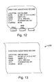
- block 252 directs the processor to run a printer driver associated with the action code to load the print buffer 117 shown in Figure 3 with printer commands which activate the printer to print a directory assistance record as shown generally at 256 in Figure 13 , using the data stored in the data registers 132 of the FSK receive buffer 112 .
- the apparatus includes a print buffer and the processor is programmed to load the print buffer for directing the printer to pnnt the user-readable representation.
- the printer also acts as a user output device for providing a user-readable representation of the information message on a printable medium.
- a user of a directory assistance provider can receive a printed record providing the telephone number of the party he/she wishes to call.
- voice recognition and conventional Interactive Voice Response (IVR) technologies may be used as alternatives to keypad or push buttons for user input.
- IVR Interactive Voice Response
- a method and apparatus provides information at a telephone.
- the method involves establishing a telephone call to a telephone services provider, answering the telephone call at the telephone services provider receiving a request for the information from the telephone at the telephone services provider during the telephone call, transmitting an information message from the telephone services provider to the telephone in response to the request during the telephone call, receiving the information message at the telephone, and, producing a user-readable representation of the information message at the telephone.
Landscapes
- Engineering & Computer Science (AREA)
- Signal Processing (AREA)
- Computer Networks & Wireless Communication (AREA)
- Business, Economics & Management (AREA)
- Accounting & Taxation (AREA)
- Computer Security & Cryptography (AREA)
- Telephonic Communication Services (AREA)
Abstract
Description
- This invention relates to a pay telephone with a printer which enables users to retrieve information from information service providers in graphical and printed form.
- Pay telephones currently exist with a conventional two-line vacuum florescent display for displaying information about telephone calls. When a pay telephone is not in use, the conventional two-line display is often used to display or scroll text which may be used for advertising to attract a user to the telephone. The use of text-only information produces a rather uninteresting advertising format.
- With the advent of the use of graphic displays in pay telephones, and with the use of the ADSI communications capabilities, advertising can be made more interesting. This type of advertising is also more effective in getting a message to the public.
- In addition, telephone service providers such as the Talking Yellow Pages (tm) currently provide information in an audio format to users making requests of such services. Use of such services, however, is valuable to only those who are satisfied in receiving data in an audio format. However, some of such information may be presented rather quickly and can be difficult to write down, for example, exchange rate information or directory assistance information.
- Users of public telephones frequently need a means of recording information provided by a Directory Assistance (DA) service, and there is a growing requirement for the user to make and retain a record of each call placed, for accounting and other purposes.
- At best, the user is equipped with a pen or pencil and paper to make appropriate notes. However, some uses may record the information by means of a knife or other sharp object, thus causing damage to the telephone booth or worse. Other users will be forced to depend upon memory, which can result in the dialling of incorrectly remembered numbers and consequently, in unnecessary expenses.
- There are situations where even a user equipped with pencil and paper will have difficulties, for example, perhaps when the number is given too quickly for the user.
- In accordance with one aspect of the invention, there is provided a method of providing information at a telephone. The method includes the steps of establishing a telephone call to a telephone services provider, answering a telephone call at a telephone service provider in response to the telephone call made from the telephone, transmitting to the telephone services provider a request for information, receiving a request for the information from the telephone at the telephone services provider during the telephone call, transmitting an information message from the telephone services provider to the telephone in response to the request, where the information message is transmitted during the telephone call, receiving the information message at the telephone, and, producing a user-readable representation of the information at the telephone.
- In one aspect of the invention, the above problems are addressed by providing the user with a printed, hardcopy record containing the number provided by the DA service, the details of a call transaction, or of other information that may be appropriately submitted to or gathered by the telephone network, and subsequently delivered via the same means.
- Preferably, the method includes the step of receiving a user-initiated request in response to user input received at the telephone.
- Preferably, the method includes the step of receiving a request which includes the step of receiving DTMF signals from the telephone.
- Preferably, the method includes the step of transmitting the information message in a pre-defined format including a message identifier and a representation of the information.
- Preferably, the method includes the step of transmitting the information message in an FSK format.
- Preferably, the method which includes the step of producing the user-readable representation includes the step of displaying the information on a graphical display at the telephone.
- Preferably, the method includes the step of printing the information message on a printable medium.
- Preferably, the method includes the step of reading the message identifier to determine the message type and executing a message handling routine associated with the message type.
- Preferably, the method includes the step of loading into a print buffer print commands for controlling a printer.
- Preferably, the method includes the step of receiving payment at the telephone for the use of the telephone services provider.
- Preferably, the method includes the step of receiving payment authorization at the telephone for the use of the telephone services provider.
- Preferably, the method includes the step of producing a call detail record relating to the telephone call.
- In accordance with another aspect of the invention, there is provided a system for providing information using a public switched telephone network. The system includes a telephone services provider which includes an answering device for answering a telephone call, a request receiver for receiving a request for the information during the telephone call, and a transmitter for transmitting an information message in response to the request during the telephone call. The system further includes at least one telephone, which includes a user input device for receiving user input from a user of the telephone, a central office interface and a dialler for establishing a telephone call to the telephone services provider in response to user-input received at the user input device, a request message transmitter for transmitting to the telephone services provider a request for information, a message receiver for receiving the information message, and a user output device for providing a user-readable representation of the information message.
- Preferably, the message receiver is operable to receive a user-initiated request in response to user input received at the telephone.
- Preferably, the receiver includes a DTMF receiver for receiving DTMF signals from the telephone.
- Preferably, the information message has a pre-defined format including a message identifier and a representation of the information.
- Preferably the transmitter includes an FSK transmitter for transmitting the information message in an FSK format.
- Preferably, the user output device includes a graphical display for displaying the information.
- Preferably, the user output device includes a printer for printing the user-readable representation on a printable medium.
- Preferably, the system includes a processor programmed to read a message identifier in the information message to determine the message type and programmed to execute a message handling routine associated with the message type.
- Preferably, the system includes a print buffer and the processor is programmed to load a print buffer for directing the printer to print the user-readable representation.
- Preferably, the processor is programmed to produce print commands for directing the printer to produce a call detail record.
- Preferably, the call detail record includes information relating a telephone call made with the telephone.
- Preferably, the system includes a payment receiver for receiving payment at the telephone for the use of the telephone services provider.
- Preferably, the system includes a payment authorization receiver for receiving payment authorization at the telephone for the use of the telephone services provider.
- In accordance with another aspect of the invention, there is provided a method of providing information at a telephone. The method includes the steps of establishing a telephone call to a telephone services provider, transmitting to the telephone services provider a request for information, during the telephone call, receiving an information message in response to the request, where the information message being transmitted during the telephone call, and producing a user-readable representation of the information message at the telephone.
- Preferably, the method includes the step of displaying the information message on a graphical display at the telephone.
- Preferably, the method which includes the step of providing the user-readable representation includes the step of printing the user-readable representation on a printable medium.
- Preferably, the method includes the step of reading a message identifier in the information message to determine the message type and executing a message handling routine associated with the message type.
- Preferably, the method which includes the step of printing includes the step of loading into a print buffer print commands for controlling the printer.
- Preferably, the method includes the step of producing a call detail record relating to the telephone call.
- Preferably, the method includes the step of receiving payment at the telephone for the use of the telephone services provider.
- Preferably, the method includes the step of receiving payment authorization at the telephone for the use of the telephone services provider.
- In accordance with another aspect of the invention, there is provided an apparatus for providing information at a telephone. The apparatus includes a central office interface and a dialler for establishing a telephone call to a telephone services provider, a request message transmitter for transmitting to the telephone services provider a request for the information, during the telephone call, an information receiver for receiving an information message in response to the request where the information message is received during the telephone call, and, an output device for providing a user-readable representation of the information message at the telephone.
- Preferably, the output device includes a graphical display for displaying the user-readable representation.
- Preferably, the output device includes a printer for printing the user-readable representation on a printable medium.
- Preferably, the apparatus includes a processor programmed to read a message identifier in the information message to determine a message type and programmed to execute a message handling routine associated with the message type.
- Preferably, the processor is programmed to produce print commands for directing the printer to print the information message.
- Preferably, the processor is programmed to produce print commands for directing the printer to produce a call detail record.
- Preferably, the call detail record includes call information relating a telephone call made with the telephone.
- Preferably, the apparatus includes a payment receiver for receiving payment at the telephone for the use of the telephone services provider.
- Preferably, the apparatus includes a payment authorization receiver for receiving payment authorization at the telephone for the use of the telephone services provider.
- In drawings which illustrate embodiments of the invention,
- Figure 1 is a block diagram of a system according to a first embodiment of the invention;
- Figure 2 is a block diagram of a telephone apparatus according to the first embodiment of the invention;
- Figure 3 is a schematic representation of a random access memory configuration, according to the first embodiment of the invention;
- Figure 4 is a schematic representation of a flash memory configuration, according to the first embodiment of the invention;
- Figure 5 is a schematic diagram of routines stored in program files in the flash memory shown in Figure 4;
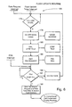
- Figure 6 is flowchart of a flash update routine, according to the first embodiment of the invention;
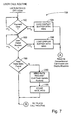
- Figure 7 is a flowchart of a user call routine, according to the first embodiment of the invention;
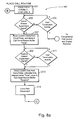
- Figure 8a is a flowchart of a place call routine, according to a first embodiment of the invention;
- Figure 8b is a continuation of Figure 8a;
- Figure 9 is a pictorial representation of a call detail record graphic image produced on a display of the apparatus shown in Figure 2;
- Figure 10 is a sample call detail record printed by a printer of the apparatus shown in Figure 2;
- Figure 11 is a flowchart of a content use routine, according to the first embodiment of the invention;
- Figure 12 is a pictorial representation of a graphic display of a directory assistance record produced by the apparatus shown in Figure 2; and
- Figure 13 is a pictorial representation of the printed directory assistance record printed by the apparatus shown in Figure 2.
-
- Referring to Figure 1, a system for providing graphical content to a plurality of graphical display pay telephones is shown generally at 10. In addition, a system for providing telephone information services by telephone, using a public switched telephone network, is shown generally at 12.
- The
system 10 includes a telephone service provider which, in this embodiment, is acentral payphone server 14, a public switched telephone network (PSTN) 16 and a plurality of graphical display telephones shown generally at 18. Both thecentral payphone server 14 and each of the plurality oftelephones 18 is operable to communicate with each other via the public switchedtelephone network 16. - The
central payphone server 14 includes aprocessor 20 which is connected to memory shown generally at 22 structured to include a link table 24, content files 26 including graphical files and rate tables. In addition, the processor is in communication with acall receiver 28 and acontent file transmitter 30. Thecall receiver 28 and thecontent file transmitter 30 are operable to receive and transmit PSK data over asubscriber loop 32 through a centraloffice line interface 34. - The
processor 20 is operable to receive from an external source, not shown, separate graphical content files 26 for each respective telephone of the plurality oftelephones 18. Thus, each telephone is associated with a corresponding set of graphical content files and rate table files. The processor uses the link table to establish correlations of graphical content files and rate table files with individual telephones of the plurality oftelephones 18. - The
call receiver 28 receives PSK signals from the centraloffice line interface 34, such PSK signals being interpreted as requests for specific content files from thememory 22. In response to such requests, theprocessor 20 retrieves a content file as determined from the link table 24 and transmits the content file using thecontent file transmitter 30 through the centraloffice line interface 34, as a phase shift keyed (PSK) information message. The PSK message includes an identifier field 36, anattribute field 38 and a data field 40. The identifier field 36 identifies the message as a graphical or rate table message, theattribute field 38 identifies certain attributes of graphical files such as time for display, effective date of display, etc. and the data field in the case of graphical files includes a bit map file for controlling pixels on a display of the telephone which sent the PSK request message. In the case of rate table files, the data field includes rate information associated with the requesting telephone. The public switched telephone network conveys the PSK message to the requesting telephone,telephone 42 for example. - Referring to Figure 2, the telephone includes a processor44 in communication with an input/output (I/O)
interface 46, Random Access Memory (RAM) 48, andflash memory 52. The I/O interface 46 is in communication with a central office line interface shown generally at 54, a keypad softkey interpreter 56, adisplay 58, aprinter 60, apayment receiver 62, ahandset 64, and aclock timer 66. - The I/
O interface 46 has amodem hookswitch output 80, a Receive Data (RXD)input 81, a Transmit Data (TXD)output 83, a voice pathhookswitch output 78, aDTMF output 82, a handset offhook detectinput 85, an RXmute output 86, an FSK input 88 aCAS input 92, and an answersupervision signal input 95. - The central
office line interface 54 interfaces the I/O interface 46 with acentral office line 55. The central office line interface includes aPSK modem 93 and aPSK modem hookswitch 79. ThePSK modem hookswitch 79 is connected to tip andring terminals PSK modem 93 for communication through thecentral office line 55. ThePSK modem hookswitch 79 has acontrol input 81 connected to themodem hookswitch output 80 such that the I/O interface is operable to control the connection of thePSK modem 93 to thecentral office line 55. The PSK modem has a receivesignal output 84 and a transmitsignal input 87 which are connected to theRXD input 81 andTXD output 83 respectively of the I/O interface to facilitate reception and transmission of data using thePSK modem 93. - The central
office line interface 54 further includes a voice path hookswitch 74, a 2-wire to 4-wire hybrid 72, aDTMF transmitter 98, an RXmute circuit 102, ahandset 64, ahandset offhook detector 65, anFSK receiver 104 and aCAS detector 108. The voice path hookswitch 74 is operable to connect the 2-wire to 4-wire hybrid 72 to the central office line. The voice path hookswitch 74 has acontrol input 76 which is connected to the voice pathhookswitch output 78 which allows the processor to control the voice path hookswitch through the I/O interface 46. The 2-wire to 4-wire hybrid has a voice transmit input 73 and a receiveoutput 75. TheDTMF transmitter 98 receives signals from theDTMF output 82 which cause it to present DTMF tones to the transmit signal input 73 for transmission over thecentral office line 55 under control of theprocessor 44. Thehandset 64 is also operable to produce voice transmit signals which are received at the input 73, also for transmission over thecentral office line 55. - The receive
output 75 is connected to the receivemute circuit 102 and the receive (RX) mute circuit has anoutput 103 which provides a receive signal to thehandset 64. The RX mute circuit is controlled by the RXmute output 86 of the I/O interface to selectively mute and unmute the receive path between the 2-wire to 4-wire hybrid and thehandset 64. - The hybrid 72 includes an answer supervision circuit 71 which produces an active answer supervision signal to the answer
supervision signal input 95 on the I/O interface 46. - The
handset offhook detector 65 provides an active handset offhook detect signal to the handset offhook detectinput 85 when the user lifts thehandset 64 off of a cradle (not shown). - The FSK receiver is connected to receive signals from the receive
output 75 and to present data representing FSK transmissions so received to theFSK input 88 at the I/O interface 46. - The
CAS detector 108 is connected to the 2-wire to 4-wire hybrid 72 to receive signals from the receiveoutput 75. TheCAS detector 108 produces an active CAS detect signal which is applied to theCAS input 92 of the I/O interface. The CAS detect signal is rendered active when a caller alerting signal (CAS) is received from the central office. - The keypad soft
key interpreter 56 provides signals to theprocessor 44 indicative of keys pressed on a dial keypad of the telephone or on softkeys adjacent thedisplay 58. Thekeypad softkey interpreter 56 thus acts as a user input device for receiving user input from a user of the telephone. - The display is a 3 inch by 4 inch pixel-addressabledisplay.
- The
printer 60 is a small receipt type printer similar to that found on cash registers. - The
payment receiver 62 is a hybrid credit card and smart card receiver, in this embodiment, and includes credit card validation software and hardware, etc., and credit card reading apparatus for reading a credit or IC-based smart card. Effectively, thepayment receiver 62 renders a payment signal active when a valid credit card (not shown) has been inserted into the credit card reader (not shown) and the credit card has been validated. The apparatus thus includes a payment authorization receiver for receiving payment authorization at the telephone for the use of the telephone services provider. - The
handset 64 is conventional and allows the user to send and receive voice signals in the usual manner over the central office line. - The
clock timer 66 provides time of day information, date information and timing information to theprocessor 44. - Referring to Figure 3, the RAM is configured to include a PSK receive buffer 110, an FSK receive buffer 112, a call detail record buffer 114, a display buffer 115 and a pnnt buffer 117.
- The PSK receive buffer includes an identification register 116, an attribute register 118, a plurality of data registers shown generally at 120 and a cyclic redundancy check register 122. The PSK receive buffer is used to receive and store messages received at the
PSK modem 93 shown in Figure 2. - Referring back to Figure 3, the FSK receive buffer 112 includes a switch to application (STA) register 124, a data link register 126, an application name register 128, an action code register 130, a plurality of data registers shown generally at 132 and a CRC register 134. The FSK receive buffer is used to receive and store messages received at the
FSK receiver 104 shown in Figure 2. - Referring back to Figure 3, the call detail record buffer 114 includes a called number register 136, a from register 140, date and time registers 144 and 146, a duration register 148, a charge register 150, a payment by register 152 and a rate register 154. The call detail record buffer 114 is used to store call detail information compiled in response to a telephone call made from the pay telephone.
- The display buffer 115 is used to hold a bit map of a graphic image for presentation on the
display 58 shown in Figure 2. - Referring back to Figure 3, the print buffer 117 is used to assemble and hold print commands for driving the
printer 60 to print a message or the like. - Referring to Figure 4, the flash memory is configured to include a display file buffer 119 a program file buffer 121 and a rate table buffer 123. The display file buffer 119, program file buffer 121 and rate table buffer 123 are loaded from data accumulated from the data registers 132 in the FSK receive buffer shown in Figure 3. The display files are loaded into the display buffer under the control of program files 121.
- Referring to Figure 4, the program file buffer 121 is preloaded with program codes readable by the
processor 44 for directing the processor to execute various routines for effecting various functions of the telephone. Such codes direct the processor to execute aflash update routine 156, auser call routine 158, aplace call routine 160, acontent use routine 162 and conventional call control anddisplay routines 164. - Referring to Figures 2 and 6, the flash update routine is shown generally at 156 and is run on a periodic basis, in this embodiment, once every 24 hours. The flash update routine begins with a
first block 176 which directs the processor to determine whether or not the telephone is in use. This is done by determining the state of the voice pathhookswitch output 78, which is set to connect the telephone to thecentral office line 55, according to the conventional call control routines when a user is using the telephone. - If at
block 176, the telephone is in use, the flash update routine continues to direct the processor to execute block 176 to continually determine whether or not the telephone is in use. When the telephone is no longer in use, block 178 directs the processor to set the voice pathhookswitch output 78 active to connect the telephone to thecentral office line 55.Block 180 then directs the processorto activate theDTMF output 82 to cause theDTMF transmitter 98 to transmit DTMF signals representing a telephone number of thecentral payphone server 14 shown in Figure 1. - Referring back to Figures 2 and 6, block 182 then directs the processor to set the
modem hookswitch output 80 active to close the modem hookswitch to connect the PSK modem to thecentral office line 55. The voice pathhookswitch output 78 is then set inactive to open the voice path hookswitch 74 to disconnect theDTMF transmitter 98 from thecentral office line 55. TheTXD output 83 is then activated with request data representing a request message. In response, the PSK modem transmits a PSK request signal to thecentral payphone server 14 through thePSTN 16. -
Block 184 then directs the processor to determine whether or not a PSK response has been received from the central payphone server within a predefined time period, t2, at thePSK modem 93. - PSK data is received at the
PSK modem 93 and is stored in the PSK receive buffer 110 shown in Figure 3 such that identification information is stored in the identification buffer, attribute information is stored in the attribute register 118, graphical data is stored in the data registers 120 and cyclic redundancy check (CRC) information is stored in the CRC register 122. The processor then calculates a CRC of its own on the contents of the identification register 116, attribute register 118 and data registers 120 and compares the calculated CRC against the contents of the CRC register 122. When the contents match, a PSK response is, for the purposes ofblock 184, deemed to have occurred. If a valid CRC is not calculated within a second time T2, block 186 directs the processor to set themodem hookswitch output 80 inactive thereby disconnecting the telephone from thecentral office line 55 and aborting the call. The flash update routine is, however, restarted atblock 176. Thus, the flash update routine persists until PSK response data is received. - When PSK data is deemed to have been received at
block 184, the processor is directed to block 188 which directs it to generate display files, program files or rate tables using the contents of the data registers 120 and to store such display files, program files or rate tables in corresponding buffers shown at 119, 121 and 123 in Figure 4. The display files are produced in a bit map format, so they can merely be copied directly into the display buffer 115 under the control of program files 121. The display files control individual pixels on thedisplay 58 according to conventional display routines. - The program files are in a format readable by the
processor 44 and are able to direct the processor to execute desired algorithms. - The rate tables are in a format readable by the
processor 44 and are used to determine a rate to be used for calculating charges for caller placed to various numbers. - After executing
block 188 of the flash update routine, this routine is completed. - Referring to Figure 7, the user call routine is shown generally at 158. This routine is entered upon the user lifting the handset, which according to the conventional call control routines, renders the handset offhook signal active.
Block 192 then directs the processor to determine whether or not a valid payment signal has been received from thepayment receiver 62. The processor remains atblock 192 until such valid payment signal is active and if such signal does not become active with a predefined time period, t3, block 194 directs the processor to load the display buffer 115 with a display file requesting the user to try again and the processor is directed to return to the conventional call control anddisplay routines 164. Otherwise, if a valid payment signal is detected, the processor is directed to block 196 where it waits for the user to place a call. The user is deemed to have placed a call when a valid telephone number has been dialled on the keypad softkey interpreter 56. The conventional telephone routines provide a flag signal (not shown) indicating whether or not the user has properly entered a valid telephone number. - If at
block 196, the user has not placed a call within a time T4, block 198 directs the processor to load the display buffer with a display file from the display file buffer 119, indicating that a call has not been properly placed and the processor is directed to return to the conventional call control and display routines. - If at
block 196, the user has dialled a valid telephone number, the processor is directed to block 199 which directs the processor to search the rate table buffer 123 for a rate table entry applicable to the number dialled by the user. - If at
block 199, no applicable rate table entry is found, the processor is directed to block 200 which directs it to send it a rate request to thecentral payphone server 14. This rate request is made by directing the processor to execute the flash update routine shown in Figure 6 whereupon the PSK request transmitted atblock 182 is a request for rate information. It will be recalled that after executing the flash update routine, the PSK receive buffer is loaded with data, in this instance, representing rate table information. - Referring back to Figure 7, upon completion of the flash Update Routine called from the user call routine, the processor is directed to block 195 which directs it to store the appropriate rate data for the call, as found in the located rate table, in the rate register 154. In addition, the processor is directed to load the called number register 136 with the number dialled by the user. In addition, the telephone number of the pay telephone used by the user is stored in the "from" register 140. Finally, the processor is also directed to load an indication of the type of payment (eg. coin, smart card, credit card) and account number, if applicable, into the "payment by" register 152.
- The processor is then directed to the place call routine shown in Figure 8.
- The Place Call routine is shown generally at 197 in Figure 8. This routine begins with a
first block 201 which directs the processor to set the voice pathhookswitch output 78 active thereby closing the voice path hookswitch 74 and connecting the voice path defined by input 73 andoutput 75 to the central office line. Thus, the processor and central office line interface act in conjunction with the DTMF transmitter which acts as a dialler for establishing a telephone call to the telephone services provider, in response to user-input received at the user input device. Still withinblock 201, the processor then controls theDTMF output 82 to cause theDTMF transmitter 98 to transmit the telephone number dialled by the user, over the central office line. - After the number is dialled, block 203 directs the processor to wait for an active answer supervision signal to be received at the answer
supervision signal input 95, from the 2-wire to 4-wire hybrid 72. Until such signal is received, the processor executes block 205 which directs it to test for call termination hookswitch activity caused by the user hanging up the handset. Such user activity may occur as a result of an abandoned call, for example. If user activity occurs, the processor is directed to abort the place call routine and return to the conventional call, control anddisplay routines 164. - If, at
block 205, no such user activity is detected and an active answer supervision signal is received atblock 203, the processor is directed to block 207. -
Block 207 directs the processor to read theclock timer 66 to determine a current date and time from theclock timer 66. The current date and time values are stored in the date and time registers 144 and 146 of the call detail record buffer 114. - The processor is then directed to block 209 where it is directed to wait for an inactive answer supervision signal from the 2-wire to 4-wire hybrid 72. If no such inactive answer supervision signal has been received, the processor is directed to block 211 where it tests for user activity including call termination hookswitch activity caused by the user hanging up the handset or user activity in the form of keypad or softkey presses at the keypad soft
key interpreter 56. If call termination activity occurs atblock 211, or if an inactive answer supervision signal is received atblock 209, the processor is directed to block 213. -
Block 213 directs the processor to again read theclock timer 66, this time to determine a new time value only. The processor then uses the presently obtained time value with the previously obtained time value as stored in the time register 146, to determine the duration of the call. The duration of the call is then stored in the duration register 148. The processor then uses the date, time and duration values in conjunction with the data stored in the rate register 154, to determine a charge value to be stored in the charge register 150. The charge value represents the cost of the call or the amount the user will be billed. The loading of the call detail record is thus completed in connection with the call just completed by the user. - The processor is then directed to block 215, where it sets the voice path
hookswitch output 78 inactive thereby opening the voice path hookswitch 74 and disconnecting the telephone from thecentral office line 55. - Referring to Figure 8b, block 217 then directs the processor to load into the display buffer 115, a display file from the display file buffer 119, the display file including a prompt message which is displayed on the
display 58 as shown in Figure 9. - The processor is then directed to block 219 where it waits for the user to press a key on the keypad or softkeys as received at the keypad soft
key interpreter 56 shown in Figure 2. If the user fails to press a keypad or softkey within a predefined period of time, the processor is returned to the conventional call control anddisplay routines 164. - If, however, at
block 219, the user activates a key at the keypad softkey interpreter 56, block 221 directs the processor to load from the program file buffer 121, an appropriate printer driver into the print buffer 117 which directs the printer to print a call detail record including the contents of registers 136 through 154 stored in the called detail record buffer. Such a record is shown generally at 254 in Figure 10. Thus, the processor is programmed to produce print commands for directing the printer to produce a call detail record and the call detail record includes information relating a telephone call made with the telephone. - Referring back to Figure 8, if at
block 209, the user has called and connected to a telephone service provider as shown at 202 in Figure 1, such provider may prompt the user, using voice, to enter 1 or 2 etc. to select certain options. For example, if the telephone services provider is a directory assistance centre, the user may be prompted to speak or enter the name of the city of the party he/she wishes to call. Spoken responses are transmitted from the payphone as conventional voice signals. Responses entered through the keypad are transmitted from the payphone as DTMF signals using theDTMF transmitter 98. Thus, the DTMF transmitter acts as a request message transmitter for transmitting to the telephone services provider a request for information, during the telephone call. - The
telephone services provider 202 receives the voice response or DTMF signals at acentral office interface 204 and provides signals to acall receiver 206. The call receiver acts as an answering device for answering a telephone call and communicates the response to aprocessor 208 which interprets the response, accesses anappropriate service application 210 and forwards information requested by the user to atransmitter 212. The transmitter formats the information into an extended ADSI message having an action code identifying the ADSI message as relating to directory assistance and data representing the information requested by the user. Thus, the information message has a pre-defined format including a message identifier and a representation of the information. Thus, the processor acts as a request receiver for receiving a request for the information during the telephone call and the transmitter transmits an information message in response to the request, during the telephone call. In addition, the processor acts as a request receiver operable to receive a user-initiated request in response to user input received at the telephone and the call receiver acts as a DTMF receiver for receiving DTMF signals from the telephone. - In accordance with the ADSI standard, the transmission of an ADSI message is preceded by a CAS tone which is detected by the
CAS detector 108, which renders a CAS signal active. The transmitter includes an FSK transmitter for transmitting the information message in an FSK format. This signal is received at theCAS input 92 of the I/O interface 46 and directs theprocessor 44 to execute a conventional ADSI message receive routine not shown but contained in the conventional call control and display routines to provide the required CAS response sequence, muting and unmuting of the receive path and reception and storage of the ADSI message in the FSK receive buffer 110 shown in Figure 3. Thus, the FSK receive buffer acts as a message receiver for receiving an information message. - After an ADSI message is received in the FSK receive buffer, the processor is directed to run the content use routine shown at 228 in Figure 11.
- Referring to Figure 11, the
content use routine 228 begins with afirst block 230 which directs theprocessor 208 to run executable routines, stored in the program files buffer 121, associated with the action code stored in the action code register 130. In the example presented, the action code relates to directory assistance information, so any executable routines associated with directory assistance activities are executed. Thus, the apparatus includes a processor programmed to read a message identifier in the information message to determine the message type and programmed to execute a message handling routine associated with the message type. - Upon completion of
block 230, the processor is directed to block 244 which directs it to produce and load a graphic display, including the contents of the data registers 132, into the display buffer 115 shown in Figure 3. Thus, the display buffer 115 is loaded with a bit map including variables from the ADSI message received from thetelephone services provider 202, and the conventional call control and display routines produce an image on a graphical display as shown in Figure 14. Thus, thedisplay 58 acts as a user output device for providing a user-readable representation of the information message on a printable medium. - Referring back to Figure 11, block 248 then directs the
processor 208 to read the keypad softkey input on the I/O interface 46 to determine whether or not the user has activated a print softkey. If the user has not activated the print softkey within a prespecified period of time T6, the processor is returned to the conventional call control and display routines. Thus, the display is returned to its original state as it was before the user made the call. - If at
block 248, the user has activated the print softkey, block 252 directs the processor to run a printer driver associated with the action code to load the print buffer 117 shown in Figure 3 with printer commands which activate the printer to print a directory assistance record as shown generally at 256 in Figure 13, using the data stored in the data registers 132 of the FSK receive buffer 112. Thus, the apparatus includes a print buffer and the processor is programmed to load the print buffer for directing the printer to pnnt the user-readable representation. Thus, the printer also acts as a user output device for providing a user-readable representation of the information message on a printable medium. - In this manner, a user of a directory assistance provider can receive a printed record providing the telephone number of the party he/she wishes to call.
- It will be appreciated that other telephone services providers such as e-mail providers, joke of the day, horoscope and the like can also provide information to one of the plurality of
telephones 18 for display in graphical format or for printout. - Alternatively, voice recognition and conventional Interactive Voice Response (IVR) technologies may be used as alternatives to keypad or push buttons for user input.
- In summary, a method and apparatus provides information at a telephone. The method involves establishing a telephone call to a telephone services provider, answering the telephone call at the telephone services provider receiving a request for the information from the telephone at the telephone services provider during the telephone call, transmitting an information message from the telephone services provider to the telephone in response to the request during the telephone call, receiving the information message at the telephone, and, producing a user-readable representation of the information message at the telephone.
- While specific embodiments of the invention have been described and illustrated, such embodiments should be considered illustrative of the invention only and not as limiting the invention as construed in accordance with the accompanying claims.
Claims (26)
- A method of providing information at a telephone, the method comprising the steps of:a) establishing a telephone call to a telephone services provider;b) answering a telephone call at a telephone services provider in response to said telephone call made from said telephone;c) transmitting a request message to said telephone services provider;d) receiving a request for said information, from said telephone, at said telephone services provider, during said telephone call;e) transmitting an information message from said telephone services provider to said telephone in response to said request, said information message being transmitted during said telephone call;f) receiving said information message at said telephone; andg) producing a user-readable representation of said information message at said telephone.
- A method as claimed in claim 1 wherein the step of receiving a request includes the step of receiving a user-initiated request in response to user input received at said telephone.
- A method as claimed in claim 1 or 2 wherein the step of receiving a request includes the step of receiving DTMF signals from said telephone.
- A method as claimed in claim 1 wherein the step of transmitting an information message further includes the step of transmitting said information message in a pre-defined format including a message identifier and a representation of said information.
- A method as claimed in claim 1 wherein the step of producing said user-readable representation includes the step of displaying said information on a graphical display at said telephone.
- A method as claimed in any preceding claim wherein the step of producing said user-readable representation includes the step of printing said information message on a printable medium.
- A method as claimed in claim 4 further including the step of reading said message identifier to determine the message type and executing a message handling routine associated with said message type.
- A method as claimed in claim 6 wherein the step of printing includes the step of loading into a print buffer print commands for controlling the printer.
- A method as claimed in any preceding claim further including the step of receiving payment at said telephone for the use of said telephone services provider.
- A method as claimed in any preceding claim further including the step of receiving payment authorization at said telephone for the use of said telephone services provider.
- A method as claimed in any preceding claim further including the step of producing a call detail record relating to said telephone call.
- A system for providing information using a public switched telephone network, the system comprising:a) telephone services provider including:i) an answering device for answering a telephone call;ii) a request receiver for receiving a request for said information during said telephone call;iii) a transmitter for transmitting an information message in response to said request, during said telephone call;b) at least one telephone, said at least one telephone including:i) a user input device for receiving user input from a user of said at least one telephone;ii) a central office line interface and a dialler for establishing a telephone call to said telephone services provider, in response to user-input received at said user input device;iii) a request message transmitter for transmitting a request message to the telephone services provider;iv) a message receiver for receiving said information message; andv) a user output device for providing a user-readable representation of said information message.
- A method of providing information at a telephone, the method comprising the steps of:a) establishing a telephone call to a telephone services provider;b) transmitting to said telephone services provider a request for said information, during said telephone call;c) receiving an information message in response to said request, said information message being transmitted during said telephone call; andd) producing a user-readable representation of said information at said telephone.
- An apparatus for providing information at a telephone, the apparatus comprising:a) a central office line interface and a dialler for establishing a telephone call to a telephone services provider;b) a request message transmitter for transmitting to said telephone services provider a request for said information, during said telephone call;c) an information receiver for receiving an information message in response to said request, said information message being received during said telephone call;d) an output device for providing a user-readable representation of said information message, at said telephone.
- A telephone, comprising:a data mechanism capable of receiving information while voice communication through a voice connection is achievable; anda printer coupled to the data mechanism, the printer being operable to print information in response to the information received by the data mechanism.
- The telephone according to claim 15, wherein the information received by the data mechanism arrives from a data connection separate from the voice connection.
- The telephone according to claim 15, wherein the information received by the data mechanism is received through the voice connection.
- A method of printing information using a telephone, the method comprising the steps of:initiating a voice connection using the telephone;the telephone receiving information while allowing voice communication through the voice connection to be achievable; andthe telephone printing information in response to the information received.
- A method of printing information using a telephone, the method comprising the steps of:initiating a telephone call using the telephone;transmitting a request message using the telephone;receiving an information message at the telephone in response to the request message; andproducing a user-readable representation of the information message using the telephone.
- A method of providing information to a telephone as set forth in claim 19, wherein said producing a user-readable representation of the information message using the telephone further includes printing the user-readable representation of the information message using the telephone.
- A telephone, comprising:a communication mechanism for communicating information;a pay mechanism coupled to the communication mechanism for enabling such communicating; anda printer coupled to the communication mechanism capable of printing information in response to information communicated by the communication mechanism.
- The telephone as set forth in claim 21, wherein the printer is integrated within the telephone.
- The telephone as set forth in claim 21, further comprising a voice mechanism for enabling voice communications.
- The telephone as set forth in claim 23, where the voice mechanism is a handset.
- The telephone as set forth in claim 21, further comprising a display mechanism for displaying graphical information.
- A telephone, comprising:a pay mechanism for enabling communication;a graphical display mechanism responsive to said communication for enabling graphical display of information associated therewith; anda printer responsive to said communication for printing information associated therewith.
Applications Claiming Priority (2)
| Application Number | Priority Date | Filing Date | Title |
|---|---|---|---|
| US99677397A | 1997-12-23 | 1997-12-23 | |
| US996773 | 1997-12-23 |
Publications (1)
| Publication Number | Publication Date |
|---|---|
| EP0926875A1 true EP0926875A1 (en) | 1999-06-30 |
Family
ID=25543299
Family Applications (1)
| Application Number | Title | Priority Date | Filing Date |
|---|---|---|---|
| EP98310575A Withdrawn EP0926875A1 (en) | 1997-12-23 | 1998-12-22 | Access terminal with printer |
Country Status (2)
| Country | Link |
|---|---|
| EP (1) | EP0926875A1 (en) |
| CA (1) | CA2254814A1 (en) |
Cited By (1)
| Publication number | Priority date | Publication date | Assignee | Title |
|---|---|---|---|---|
| EP1310084A1 (en) * | 2000-04-17 | 2003-05-14 | Shawn E. Wiederin | Method for charging on-line directory assistance services |
Citations (5)
| Publication number | Priority date | Publication date | Assignee | Title |
|---|---|---|---|---|
| US4918722A (en) * | 1988-05-11 | 1990-04-17 | Brooktrout Technology, Inc. | Control of electronic information delivery |
| US5555290A (en) * | 1990-04-23 | 1996-09-10 | Mci Communications Corporation | Long distance telephone switching system with enhanced subscriber services |
| WO1997004579A1 (en) * | 1995-07-14 | 1997-02-06 | American Express Trs | Method and apparatus for generating summaries of prepaid instrument transaction activity |
| US5615257A (en) * | 1994-01-04 | 1997-03-25 | Northern Telecom Limited | Screen-based telephone set for interactive enhanced telephony service |
| WO1997012479A1 (en) * | 1995-09-29 | 1997-04-03 | Teligent Ab | A communication and service terminal |
-
1998
- 1998-11-30 CA CA002254814A patent/CA2254814A1/en not_active Abandoned
- 1998-12-22 EP EP98310575A patent/EP0926875A1/en not_active Withdrawn
Patent Citations (5)
| Publication number | Priority date | Publication date | Assignee | Title |
|---|---|---|---|---|
| US4918722A (en) * | 1988-05-11 | 1990-04-17 | Brooktrout Technology, Inc. | Control of electronic information delivery |
| US5555290A (en) * | 1990-04-23 | 1996-09-10 | Mci Communications Corporation | Long distance telephone switching system with enhanced subscriber services |
| US5615257A (en) * | 1994-01-04 | 1997-03-25 | Northern Telecom Limited | Screen-based telephone set for interactive enhanced telephony service |
| WO1997004579A1 (en) * | 1995-07-14 | 1997-02-06 | American Express Trs | Method and apparatus for generating summaries of prepaid instrument transaction activity |
| WO1997012479A1 (en) * | 1995-09-29 | 1997-04-03 | Teligent Ab | A communication and service terminal |
Cited By (6)
| Publication number | Priority date | Publication date | Assignee | Title |
|---|---|---|---|---|
| EP1310084A1 (en) * | 2000-04-17 | 2003-05-14 | Shawn E. Wiederin | Method for charging on-line directory assistance services |
| EP1310084A4 (en) * | 2000-04-17 | 2003-07-09 | Shawn E Wiederin | Method for charging on-line directory assistance services |
| US7069446B2 (en) | 2000-04-17 | 2006-06-27 | Mci, Llc | Stateless mechanism for data retrieval |
| US7127617B2 (en) | 2000-04-17 | 2006-10-24 | Mci, Llc | On-line directory assistance system |
| US7275162B2 (en) | 2000-04-17 | 2007-09-25 | Verizon Business Global Llc | On-line directory assistance system |
| US7640166B2 (en) | 2000-04-17 | 2009-12-29 | Verizon Business Global Llc | Method for charging on-line directory assistance services |
Also Published As
| Publication number | Publication date |
|---|---|
| CA2254814A1 (en) | 1999-06-23 |
Similar Documents
| Publication | Publication Date | Title |
|---|---|---|
| US6163598A (en) | Interactive graphic payphone | |
| US5561705A (en) | Apparatus for auto dialing telephone numbers and DTMF tones in a personal communication device | |
| US5619725A (en) | Method for auxiliary software providing instruction for facsimile modem to simulate a telephone communication while connecting to store and forward computer to receive communication | |
| EP0949829A2 (en) | Mobile radio terminal and method for communicating short messages | |
| US20030045267A1 (en) | Caller-initiated transfer of services between telephones | |
| EP0981236A1 (en) | Text-enhanced voice menu system | |
| JPH08500952A (en) | Memory dialing method for cellular phones | |
| RU2004116330A (en) | TERMINAL COMMUNICATION DEVICE HAVING PERSONALIZATION MEANS | |
| US20040101118A1 (en) | Caller identification data management | |
| US6104787A (en) | Method and apparatus for transmitting information in response to a verbal or otherwise audible request therefore | |
| EP0926875A1 (en) | Access terminal with printer | |
| KR100762642B1 (en) | Method for displaying sms message background picture in terminal including sms function and terminal thereof | |
| KR100222781B1 (en) | Telephone number searching method | |
| KR100565440B1 (en) | Method and apparatus of providing text scenario for voice information service device using interactive sms | |
| EP1032228A2 (en) | A method and a cellular telecommunication apparatus for converting currencies | |
| KR200203361Y1 (en) | A phone has function of calling identity delivery and auto dial | |
| MXPA98009050A (en) | Method and apparatus for visually presenting graphical data associated with a telephone transmission | |
| US20060211424A1 (en) | Method for establishing a collect call through a wireless communication system | |
| JP3503374B2 (en) | Public terminal | |
| KR20010110254A (en) | Method for implementing automatic dialing in cordless phone incorporating card reader and thereof | |
| KR19990016717A (en) | Internet payphones and their use | |
| KR100352230B1 (en) | Public telephone system having things providing function and Method for using of it | |
| JPH0456474A (en) | Facsimile communication equipment | |
| JPS6030249A (en) | Receiver for character information | |
| KR100831612B1 (en) | Apparatus and method for transfering voice messages and short messages in parallel between automatic response system and telephone connecting thereto |
Legal Events
| Date | Code | Title | Description |
|---|---|---|---|
| PUAI | Public reference made under article 153(3) epc to a published international application that has entered the european phase |
Free format text: ORIGINAL CODE: 0009012 |
|
| AK | Designated contracting states |
Kind code of ref document: A1 Designated state(s): DE FR GB |
|
| AX | Request for extension of the european patent |
Free format text: AL;LT;LV;MK;RO;SI |
|
| RAP3 | Party data changed (applicant data changed or rights of an application transferred) |
Owner name: NORTEL NETWORKS CORPORATION |
|
| 17P | Request for examination filed |
Effective date: 19991230 |
|
| AKX | Designation fees paid |
Free format text: DE FR GB |
|
| RAP1 | Party data changed (applicant data changed or rights of an application transferred) |
Owner name: NORTEL NETWORKS LIMITED |
|
| RAP1 | Party data changed (applicant data changed or rights of an application transferred) |
Owner name: NORTEL NETWORKS LIMITED |
|
| STAA | Information on the status of an ep patent application or granted ep patent |
Free format text: STATUS: THE APPLICATION IS DEEMED TO BE WITHDRAWN |
|
| 18D | Application deemed to be withdrawn |
Effective date: 20030702 |