EP0928594B1 - Upright vacuum cleaner with cyclonic airflow - Google Patents
Upright vacuum cleaner with cyclonic airflow Download PDFInfo
- Publication number
- EP0928594B1 EP0928594B1 EP98104806A EP98104806A EP0928594B1 EP 0928594 B1 EP0928594 B1 EP 0928594B1 EP 98104806 A EP98104806 A EP 98104806A EP 98104806 A EP98104806 A EP 98104806A EP 0928594 B1 EP0928594 B1 EP 0928594B1
- Authority
- EP
- European Patent Office
- Prior art keywords
- suction
- vacuum cleaner
- upright
- housing section
- filter
- Prior art date
- Legal status (The legal status is an assumption and is not a legal conclusion. Google has not performed a legal analysis and makes no representation as to the accuracy of the status listed.)
- Expired - Lifetime
Links
Images


Classifications
-
- B—PERFORMING OPERATIONS; TRANSPORTING
- B04—CENTRIFUGAL APPARATUS OR MACHINES FOR CARRYING-OUT PHYSICAL OR CHEMICAL PROCESSES
- B04C—APPARATUS USING FREE VORTEX FLOW, e.g. CYCLONES
- B04C9/00—Combinations with other devices, e.g. fans, expansion chambers, diffusors, water locks
-
- A—HUMAN NECESSITIES
- A47—FURNITURE; DOMESTIC ARTICLES OR APPLIANCES; COFFEE MILLS; SPICE MILLS; SUCTION CLEANERS IN GENERAL
- A47L—DOMESTIC WASHING OR CLEANING; SUCTION CLEANERS IN GENERAL
- A47L5/00—Structural features of suction cleaners
- A47L5/12—Structural features of suction cleaners with power-driven air-pumps or air-compressors, e.g. driven by motor vehicle engine vacuum
- A47L5/22—Structural features of suction cleaners with power-driven air-pumps or air-compressors, e.g. driven by motor vehicle engine vacuum with rotary fans
- A47L5/28—Suction cleaners with handles and nozzles fixed on the casings, e.g. wheeled suction cleaners with steering handle
-
- A—HUMAN NECESSITIES
- A47—FURNITURE; DOMESTIC ARTICLES OR APPLIANCES; COFFEE MILLS; SPICE MILLS; SUCTION CLEANERS IN GENERAL
- A47L—DOMESTIC WASHING OR CLEANING; SUCTION CLEANERS IN GENERAL
- A47L9/00—Details or accessories of suction cleaners, e.g. mechanical means for controlling the suction or for effecting pulsating action; Storing devices specially adapted to suction cleaners or parts thereof; Carrying-vehicles specially adapted for suction cleaners
- A47L9/10—Filters; Dust separators; Dust removal; Automatic exchange of filters
- A47L9/12—Dry filters
- A47L9/127—Dry filters tube- or sleeve-shaped
-
- A—HUMAN NECESSITIES
- A47—FURNITURE; DOMESTIC ARTICLES OR APPLIANCES; COFFEE MILLS; SPICE MILLS; SUCTION CLEANERS IN GENERAL
- A47L—DOMESTIC WASHING OR CLEANING; SUCTION CLEANERS IN GENERAL
- A47L9/00—Details or accessories of suction cleaners, e.g. mechanical means for controlling the suction or for effecting pulsating action; Storing devices specially adapted to suction cleaners or parts thereof; Carrying-vehicles specially adapted for suction cleaners
- A47L9/10—Filters; Dust separators; Dust removal; Automatic exchange of filters
- A47L9/16—Arrangement or disposition of cyclones or other devices with centrifugal action
- A47L9/165—Construction of inlets
-
- A—HUMAN NECESSITIES
- A47—FURNITURE; DOMESTIC ARTICLES OR APPLIANCES; COFFEE MILLS; SPICE MILLS; SUCTION CLEANERS IN GENERAL
- A47L—DOMESTIC WASHING OR CLEANING; SUCTION CLEANERS IN GENERAL
- A47L9/00—Details or accessories of suction cleaners, e.g. mechanical means for controlling the suction or for effecting pulsating action; Storing devices specially adapted to suction cleaners or parts thereof; Carrying-vehicles specially adapted for suction cleaners
- A47L9/10—Filters; Dust separators; Dust removal; Automatic exchange of filters
- A47L9/16—Arrangement or disposition of cyclones or other devices with centrifugal action
- A47L9/1658—Construction of outlets
- A47L9/1666—Construction of outlets with filtering means
-
- A—HUMAN NECESSITIES
- A47—FURNITURE; DOMESTIC ARTICLES OR APPLIANCES; COFFEE MILLS; SPICE MILLS; SUCTION CLEANERS IN GENERAL
- A47L—DOMESTIC WASHING OR CLEANING; SUCTION CLEANERS IN GENERAL
- A47L9/00—Details or accessories of suction cleaners, e.g. mechanical means for controlling the suction or for effecting pulsating action; Storing devices specially adapted to suction cleaners or parts thereof; Carrying-vehicles specially adapted for suction cleaners
- A47L9/10—Filters; Dust separators; Dust removal; Automatic exchange of filters
- A47L9/16—Arrangement or disposition of cyclones or other devices with centrifugal action
- A47L9/1683—Dust collecting chambers; Dust collecting receptacles
-
- B—PERFORMING OPERATIONS; TRANSPORTING
- B01—PHYSICAL OR CHEMICAL PROCESSES OR APPARATUS IN GENERAL
- B01D—SEPARATION
- B01D39/00—Filtering material for liquid or gaseous fluids
- B01D39/14—Other self-supporting filtering material ; Other filtering material
- B01D39/16—Other self-supporting filtering material ; Other filtering material of organic material, e.g. synthetic fibres
- B01D39/1692—Other shaped material, e.g. perforated or porous sheets
-
- B—PERFORMING OPERATIONS; TRANSPORTING
- B01—PHYSICAL OR CHEMICAL PROCESSES OR APPARATUS IN GENERAL
- B01D—SEPARATION
- B01D45/00—Separating dispersed particles from gases or vapours by gravity, inertia, or centrifugal forces
- B01D45/12—Separating dispersed particles from gases or vapours by gravity, inertia, or centrifugal forces by centrifugal forces
- B01D45/16—Separating dispersed particles from gases or vapours by gravity, inertia, or centrifugal forces by centrifugal forces generated by the winding course of the gas stream, the centrifugal forces being generated solely or partly by mechanical means, e.g. fixed swirl vanes
-
- B—PERFORMING OPERATIONS; TRANSPORTING
- B01—PHYSICAL OR CHEMICAL PROCESSES OR APPARATUS IN GENERAL
- B01D—SEPARATION
- B01D46/00—Filters or filtering processes specially modified for separating dispersed particles from gases or vapours
- B01D46/10—Particle separators, e.g. dust precipitators, using filter plates, sheets or pads having plane surfaces
-
- B—PERFORMING OPERATIONS; TRANSPORTING
- B01—PHYSICAL OR CHEMICAL PROCESSES OR APPARATUS IN GENERAL
- B01D—SEPARATION
- B01D46/00—Filters or filtering processes specially modified for separating dispersed particles from gases or vapours
- B01D46/24—Particle separators, e.g. dust precipitators, using rigid hollow filter bodies
- B01D46/2403—Particle separators, e.g. dust precipitators, using rigid hollow filter bodies characterised by the physical shape or structure of the filtering element
- B01D46/2411—Filter cartridges
-
- B—PERFORMING OPERATIONS; TRANSPORTING
- B01—PHYSICAL OR CHEMICAL PROCESSES OR APPARATUS IN GENERAL
- B01D—SEPARATION
- B01D46/00—Filters or filtering processes specially modified for separating dispersed particles from gases or vapours
- B01D46/52—Particle separators, e.g. dust precipitators, using filters embodying folded corrugated or wound sheet material
- B01D46/521—Particle separators, e.g. dust precipitators, using filters embodying folded corrugated or wound sheet material using folded, pleated material
-
- B—PERFORMING OPERATIONS; TRANSPORTING
- B01—PHYSICAL OR CHEMICAL PROCESSES OR APPARATUS IN GENERAL
- B01D—SEPARATION
- B01D50/00—Combinations of methods or devices for separating particles from gases or vapours
- B01D50/20—Combinations of devices covered by groups B01D45/00 and B01D46/00
-
- B—PERFORMING OPERATIONS; TRANSPORTING
- B04—CENTRIFUGAL APPARATUS OR MACHINES FOR CARRYING-OUT PHYSICAL OR CHEMICAL PROCESSES
- B04C—APPARATUS USING FREE VORTEX FLOW, e.g. CYCLONES
- B04C5/00—Apparatus in which the axial direction of the vortex is reversed
- B04C5/12—Construction of the overflow ducting, e.g. diffusing or spiral exits
- B04C5/13—Construction of the overflow ducting, e.g. diffusing or spiral exits formed as a vortex finder and extending into the vortex chamber; Discharge from vortex finder otherwise than at the top of the cyclone; Devices for controlling the overflow
-
- B—PERFORMING OPERATIONS; TRANSPORTING
- B01—PHYSICAL OR CHEMICAL PROCESSES OR APPARATUS IN GENERAL
- B01D—SEPARATION
- B01D2279/00—Filters adapted for separating dispersed particles from gases or vapours specially modified for specific uses
- B01D2279/55—Filters adapted for separating dispersed particles from gases or vapours specially modified for specific uses for cleaning appliances, e.g. suction cleaners
-
- B—PERFORMING OPERATIONS; TRANSPORTING
- B04—CENTRIFUGAL APPARATUS OR MACHINES FOR CARRYING-OUT PHYSICAL OR CHEMICAL PROCESSES
- B04C—APPARATUS USING FREE VORTEX FLOW, e.g. CYCLONES
- B04C9/00—Combinations with other devices, e.g. fans, expansion chambers, diffusors, water locks
- B04C2009/004—Combinations with other devices, e.g. fans, expansion chambers, diffusors, water locks with internal filters, in the cyclone chamber or in the vortex finder
-
- Y—GENERAL TAGGING OF NEW TECHNOLOGICAL DEVELOPMENTS; GENERAL TAGGING OF CROSS-SECTIONAL TECHNOLOGIES SPANNING OVER SEVERAL SECTIONS OF THE IPC; TECHNICAL SUBJECTS COVERED BY FORMER USPC CROSS-REFERENCE ART COLLECTIONS [XRACs] AND DIGESTS
- Y10—TECHNICAL SUBJECTS COVERED BY FORMER USPC
- Y10S—TECHNICAL SUBJECTS COVERED BY FORMER USPC CROSS-REFERENCE ART COLLECTIONS [XRACs] AND DIGESTS
- Y10S55/00—Gas separation
- Y10S55/03—Vacuum cleaner
Definitions
- the present invention relates to vacuum cleaners. More particularly, the present invention relates to upright vacuum cleaners used for suctioning dirt and debris from carpets and floors.
- Upright vacuum cleaners are ubiquitous. They are known to include an upper portion having a handle, by which an operator of the vacuum cleaner may grasp and maneuver the cleaner, and a lower cleaning nozzle portion which travels across a floor, carpet, or other surface being cleaned.
- the upper portion is often formed as a rigid plastic housing which encloses a dirt and dust collecting filter bag, although the upper portion may simply be an elongated handle with the filter bag, and an external cloth bag, being hung therefrom.
- the cleaning nozzle is hingedly connected to the upper handle portion such that the upper portion is pivotable between a generally vertical upright storage position and an inclined operative position.
- the underside of the nozzle includes a suction opening formed therein which is in fluid communication with the filter bag.
- a vacuum or suction source such as a motor and fan assembly is enclosed either within the nozzle portion or the upper portion of the cleaner.
- the vacuum source generates the suction required to pull dirt from the carpet or floor being vacuumed through the suction opening and into the filter bag.
- a rotating brush assembly is typically provided in proximity with the suction opening to loosen dirt and debris from the surface being vacuumed.
- another type of upright vacuum cleaner utilizes cyclonic airflow, rather than a filter bag, to separate a majority of the dirt and other particulates from the suction airstream. The air is then filtered to remove residual particulates, returned to the motor, and exhausted.
- a vacuum cleaner in accordance with the pre-characterizing part of claim 1 is disclosed in EP-A-00 42 723.
- a new and improved upright vacuum cleaner is provided. This is attained with the vacuum cleaner according to claim 1.
- An upright vacuum cleaner includes a housing defining a cyclonic airflow chamber for separating contaminants from a suction airstream.
- the housing includes a suction airstream inlet and a suction airstream outlet in fluid communication with the cyclonic airflow chamber.
- a nozzle base includes a main suction opening which is fluidically connected with said cyclonic airflow chamber inlet.
- An airstream suction source is provided and has an inlet fluidically connected to said cyclonic airflow chamber outlet and a suction source exhaust outlet. The suction source selectively establishes and maintains a suction airstream from the nozzle main suction opening to the suction source exhaust outlet.
- a main filter assembly is positioned in fluid communication between the cyclonic airflow chamber and the suction source for filtering residual contaminants from the suction airstream downstream relative to the cyclonic airflow chamber.
- the main filter assembly comprises a filter element including high-density polyethylene porous filter media.
- a vacuum cleaner in accordance with an aspect of the invention, includes an upright housing section including a handle.
- a nozzle base section is hingedly interconnected with the upright housing section and includes a main suction opening formed in an underside thereof.
- a cyclonic airflow chamber is defined in the upright housing section and separates dust and dirt from a suction airstream.
- a suction source is located in the upright section or the nozzle section and has a suction airflow inlet in fluid communication with the cyclonic chamber and a suction airflow outlet.
- a main filter assembly is located between the cyclonic chamber and the suction source for filtering residual dust and dirt from the suction airstream after the suction airstream passes through the cyclonic airflow chamber.
- a final filter assembly is located on either the housing or the nozzle base and is connected in fluid communication with the suction airflow outlet of the suction source for filtering the suction airstream exhausted by the suction source prior to the suction airstream being dispersed into the atmosphere.
- a vacuum cleaner includes a nozzle section.
- a housing section is connected to the nozzle section and is in fluid communication with the nozzle section.
- a cyclonic airflow chamber is located in the housing section for separating dirt and dust from a suction airstream flowing into the housing section between an inlet located at a periphery of the housing section and an outlet located at an apex of the housing section.
- a filter chamber is located in the housing section between the cyclonic airflow chamber and the outlet of the housing section.
- the filter chamber includes a first filter housing and a first filter element mounted in the first filter housing. The first filter element and the first filter housing cooperate to define a tortuous flow path for air flowing from the cyclonic airflow chamber to the outlet of the housing section.
- One advantage of the present invention is the provision of a new and improved vacuum cleaner.
- Another advantage of the invention is found in the provision of a vacuum cleaner with a cyclonic airflow chamber through which the suction airstream flows for separating dust and dirt from the airstream and for depositing the separated dust and dirt into an easily and conveniently emptied dirt cup.
- Still another advantage of the present invention resides in the provision of a cyclonic airflow upright vacuum cleaner with a main filter that effectively filters residual contaminants from the suction airstream between the cyclonic airflow chamber and the motor assembly without unduly restricting airflow and without premature clogging.
- Yet another advantage of the invention is the provision of a cyclonic airflow upright vacuum cleaner with a final filter located downstream from the suction motor assembly for filtering the suction airstream immediately prior to its exhaustion into the atmosphere.
- a further advantage of the invention is the provision of a vacuum cleaner with both a main filter and a final filter wherein both the main and final filter are easily removable and replaceable.
- a still further advantage of the present invention is the provision of a vacuum cleaner with a filter element mounted in a filter housing wherein the filter element and filter housing cooperate to provide a tortuous flow path for air flowing therethrough.
- FIGURES 1-6 illustrate an upright vacuum cleaner A including an upright housing section B and a nozzle base section C.
- the sections B,C are pivotally or hingedly connected through the use of trunnions or another suitable hinge assembly D so that the upright housing section B pivots between a generally vertical storage position (as shown) and an inclined operative position.
- Both the upright and nozzle sections B,C are preferably made from conventional materials such as molded plastics and the like.
- the upright section B includes a handle 20 extending upward therefrom by which an operator of the vacuum A is able to grasp and maneuver the vacuum.
- the underside 24 (FIGURE 6) of the nozzle includes a main suction opening 26 formed therein which extends substantially across the width of the nozzle at the front end thereof.
- the main suction opening 26 is in fluid communication with the vacuum upright body section B through a passage 30 and a connector hose assembly 34 (FIGURE 5).
- a rotating brush assembly 36 is positioned in the region of the nozzle main suction opening 26 for contacting and scrubbing the surface being vacuumed to loosen embedded dirt and dust.
- a plurality of wheels 38 support the nozzle on the surface being cleaned and facilitate its movement thereacross.
- the upright vacuum cleaner A includes a vacuum or suction source for generating the required suction airflow for cleaning operations.
- a suitable suction source such as an electric motor and fan assembly E, generates a suction force in a suction inlet 40 an exhaust force in an exhaust outlet 42.
- the motor assembly airflow exhaust outlet 42 is in fluid communication with a final filter assembly F for filtering the exhaust airstream of any contaminants immediately prior to its discharge into the atmosphere.
- the motor assembly suction inlet 40 is in fluid communication with an elongated suction conduit 46 which extends upward from the motor/fan assembly E to an upper region of the upright section B where it communicates with the cyclonic suction airflow dust and dirt separating region G of the vacuum A to generate a suction force therein.
- the cyclonic suction airflow dust and dirt separating region G housed in the upright section B includes a main filter housing assembly 50 and a mating dust and dirt cup or container 52.
- the sections 50,52 together define a generally cylindrical cyclonic airflow chamber 54.
- the main filter housing assembly 50 is, itself, constructed from two mating sections - an upper fixed housing section 50a, and a lower, detachable filter housing section 50b.
- the lower detachable filter housing section 50b receives and retains a main filter element or cartridge H.
- the filter housing section 50b releasably connects with the upper housing section 50a to secure the filter element H in an operative filtering position. More particularly, the section 50b includes a plurality of tabs or tangs 54b extending therefrom.
- the upper housing section 50a includes mating tabs or tangs 54a.
- the components 50a,50b connect in a key-like fashion upon rotation of the filter housing section 50b in relation to the upper housing section 50a so that a filter element H is operatively secured in position.
- the two housing sections 50a,50b may alternatively include mating threads, clips, or other suitable cooperating fastening means.
- the filter housing section 50b includes a plurality of apertures, slots, or other passages 56 formed therethrough, preferably in the lower half thereof, so that the suction airstream flows freely from the chamber 54 into the filter housing section 50b and to the main filter element H.
- the housing upper section 50a includes a suction airflow outlet passage 60 (FIGURE 8) which communicates with the cyclonic chamber 54 through an aperture 62.
- the outlet passage 60 also communicates with the elongated suction conduit 46 leading to the motor/fan assembly E when the main filter housing assembly 50 is operatively connected to the vacuum upright section B.
- FIGURES 8 and 9 show that the elongated suction conduit 46 extends from the motor/fan assembly E upward to communicate with the main filter housing suction outlet passage 60 so that the suction inlet of the motor/fan assembly E is able to fluidically communicate with the cyclonic chamber 54.
- a mouth 66 (FIGURE 10) of the filter element H mates with the periphery of the aperture 62 in a fluid-tight relationship.
- the suction airflow from the cyclonic chamber 54 to the motor/fan assembly suction inlet 42 is not able to bypass the main filter element H, but instead must pass therethrough and be filtered of residual contaminants.
- the aperture 62, and thus the main filter element H be centrally located in the cyclonic chamber 54 to facilitate the cyclonic airflow in the chamber.
- the suction airstream enters an upper portion of the cyclonic dust and dirt separation chamber 54 through a generally tangential suction airstream inlet 80.
- the cyclonic chamber airstream inlet 80 is formed in the upper section 50a of the main filter housing assembly 50. It is noted that the inlet 80 is disposed entirely on one side of a center line 81 of the upper housing section so as to induce a swirling flow around the filter housing section 50b.
- the suction airstream inlet 80 of the chamber 54 is in fluid communication with a suction airstream hose 82 through a fitting 84.
- the hoses 82,34 are fluidically connected via fitting 86.
- the main suction opening 26 formed in the nozzle underside 24 is in fluid communication with the cyclonic chamber 54 through the passage 30, the hoses 34,82, and the cyclonic chamber suction inlet 80.
- the dirt container 52 of the cyclonic airflow dust and dirt separating assembly G is constructed for large capacity and ease of emptying the contents as necessary.
- FIGURE 8 it may be seen that the dirt container 52 defines over 1 ⁇ 2 the volume of the cyclonic chamber 54. As such, the capacity of the container 52 is maximized to lengthen the operational time before the dirt container 52 must be emptied.
- the dirt container 52 is connected to the vacuum upright section B through use of a hinge 90 which allows the dirt container 52 to pivot as indicated by the arrow I between an operative upright position and an open forwardly tilted position.
- the hinge 90 comprises a first component 92 connected to the dirt container 52 and a second mating component 94 formed on the upright section B.
- the dirt container upper edge 100 defining an open upper end of the container 52 is preferably inclined downwardly in the direction away from the handle 96 or front of the container 52.
- the main filter housing assembly section 50 is formed with a complimentary mating inclined edge 102, and a seal such as a gasket or other structure (not shown) is provided between the edges 100,102 to prevent air leakage into the cyclonic airflow chamber 54.
- the inclined upper edge 100 of the dirt container 52 also ensures that, when the container is pivoted to the open position, the upper edge 100 lies in a substantially horizontal plane. As such, the contents of the container are much less likely to spill when the container is opened during emptying operations.
- the angle at which the upper edge 100 is inclined from horizontal is selected, in combination with the maximum distance the container is able to be pivoted on the arc I when opened, such that when the container is fully opened, the upper edge lies in a substantially horizontal plane.
- the main filter element H is preferably generally frusto-conical in overall configuration, converging in the direction away from the filter mouth 66 toward an opposite filter end 110.
- a cylindrical or other filter configuration may be advantageously employed without departing from the scope and overall intent of the invention.
- the preferred filter media comprises Porex® brand high density polyethylene-based open-celled porous media available commercially from Porex Technologies Corp., Fairburn, Georgia 30213, or an equivalent foraminous filter media.
- This preferred filter media is a rigid open-celled foam that is moldable, machinable, and otherwise workable into any shape as deemed advantageous for a particular application.
- the preferred filter media has an average pore size in the range of 45 ⁇ m to 90 ⁇ m.
- the filter H is most preferably formed in a convoluted or circuitous configuration to maximize an outer surface area 112 of the filter.
- the maximized surface area 112 allows for the filter media to have a smaller pore size without unduly restricting the airflow therethrough.
- the filter media is formed into at least two elongated and concentric cylinders and/or frustums 114a,114b with a deep annular passage 116 defined therebetween.
- a deep central passage 118 is defined in the innermost cylinder or frustum 114a.
- FIGURE 13D illustrates such an alternative configuration of the main filter element H'.
- the filter element H' is formed by concentric cylindrical portions 114a',114b' separated by a deep annular passage 116'. However, unlike the main filter element H, the element H' does not include a deep central passage formed in the inner cylinder 114a'.
- the subject vacuum A also comprises a final filter assembly F for filtering the suction airstream downstream from the motor/fan assembly and immediately prior to its exhaustion into the atmosphere.
- the preferred final filter assembly F is illustrated most clearly in FIGURE 11 and comprises a suction airstream inlet 120 which is connected in fluid communication with the exhaust outlet 42 of the motor and fan assembly E.
- the inlet 120 is itself in fluid communication with an elongated plenum 122 that opens to the atmosphere and houses filter media.
- a protective grid or grate structure is snap-fit or otherwise effectively secured over the plenum 122 to secure the filter media in place.
- the filter media is preferably a high efficiency particulate arrest (HEPA) filter element in a sheet or block form.
- HEPA high efficiency particulate arrest
- the filter media is retained in position in the plenum by the grid 124, but is easily replaced by removing the grid. As such, those skilled in the art will recognize that even if the motor/fan assembly causes contaminants to be introduced into the suction airstream downstream from the main filter element H, the final filter assembly F will remove the same such that only contaminant-free air is discharged into the atmosphere.
- FIGURES 8 and 14 the operation of the vacuum cleaning apparatus A is illustrated, with the flow of the suction airstream indicated by use of arrows J.
- the motor/fan assembly E or other suction generator establishes a suction force at its suction inlet 42, in the elongated suction conduit 46, and thus in the cyclonic separation chamber 54 .
- This suction force or negative pressure in the chamber 54 is communicated to the main suction opening 26 formed in the nozzle underside 24 through the hoses 82,34 (FIGURE 5) and associated fittings.
- This, then, in combination with the scrubbing action of the rotating brush assembly 36 causes dust and dirt from the surface being cleaned to be entrained in the suction airflow J and pulled into the upper portion of the chamber 54 through the generally tangential inlet 80.
- the location of the inlet 80, the outlet passage 60, and the generally cylindrical configuration of the chamber 54 causes the suction airstream to follow a swirling or cyclonic path downward within the chamber 54 and then to move upward through a central portion of the chamber 54 toward the centrally located main filter housing section 50b.
- the orientation of the inlet 80 will affect the direction of cyclonic airflow, and the invention is not meant to be limited to a particular direction, i.e, clockwise or counterclockwise. Those skilled in the art will certainly recognize that the term "cyclonic" as used herein is not meant to be limited to a particular direction of airflow rotation.
- This cyclonic action separates a substantial portion of the entrained dust and dirt from the suction airstream and causes the dust and dirt to be deposited in the dirt cup or container 52.
- the suction airstream then passes through the apertures 56 formed in the main filter housing section 50b, passes through the main filter element H so that residual contaminants are removed, and exits the cyclonic chamber 54 through the suction airstream outlet passage 60 formed in the main filter housing section 50a.
- the suction airstream is communicated to the motor/fan assembly E and exhausted through the outlet 42 (as indicated by broken arrows) to the final filter assembly F where it is filtered again by the HEPA filter to remove any contaminants that passed through the chamber 54 and the filter H, and any contaminants in the airstream due to its passage through the motor/fan assembly E.
- the main filter element H can be cleaned by washing it, either manually or in a dishwasher -- since it is dishwasher-safe -- to remove dust or dirt particles adhering to the filter element. It is, however, important that the filter H be dried before it is used again.
- the final filter media of the filter assembly F can not be cleaned and must be replaced when it becomes clogged.
Abstract
Description
- The present invention relates to vacuum cleaners. More particularly, the present invention relates to upright vacuum cleaners used for suctioning dirt and debris from carpets and floors.
- Upright vacuum cleaners are ubiquitous. They are known to include an upper portion having a handle, by which an operator of the vacuum cleaner may grasp and maneuver the cleaner, and a lower cleaning nozzle portion which travels across a floor, carpet, or other surface being cleaned. The upper portion is often formed as a rigid plastic housing which encloses a dirt and dust collecting filter bag, although the upper portion may simply be an elongated handle with the filter bag, and an external cloth bag, being hung therefrom. The cleaning nozzle is hingedly connected to the upper handle portion such that the upper portion is pivotable between a generally vertical upright storage position and an inclined operative position. The underside of the nozzle includes a suction opening formed therein which is in fluid communication with the filter bag.
- A vacuum or suction source such as a motor and fan assembly is enclosed either within the nozzle portion or the upper portion of the cleaner. The vacuum source generates the suction required to pull dirt from the carpet or floor being vacuumed through the suction opening and into the filter bag. A rotating brush assembly is typically provided in proximity with the suction opening to loosen dirt and debris from the surface being vacuumed.
- To avoid the need for vacuum filter bags, and the associated expense and inconvenience of replacing the bag, another type of upright vacuum cleaner utilizes cyclonic airflow, rather than a filter bag, to separate a majority of the dirt and other particulates from the suction airstream. The air is then filtered to remove residual particulates, returned to the motor, and exhausted.
- Such prior cyclonic airflow upright vacuum cleaners have not been found to be entirely effective and convenient to use. For example, with these prior cyclonic airflow vacuum cleaners, the process of emptying dust and dirt from the cyclonic chamber dirt collection container has been found to be inconvenient, and often resulted in the spillage of the cup contents. Likewise, with these prior units, replacement of the filter element has not been convenient. Other cyclonic airflow vacuum cleaners have been found to exhaust air which is not free of residual contaminants. For example, one prior unit filters the airstream after it passes through the cyclonic chamber, but thereafter passes the airstream through the motor assembly where it is potentially recontaminated by the motor assembly, itself, prior to its being exhausted into the atmosphere.
- Because the cyclonic action of such vacuum cleaners does not completely remove all dust, dirt, and other contaminants from the suction airstream, it is necessary to include a filter downstream from the cyclonic chamber. As such, prior cyclonic airflow vacuum cleaners have heretofore included conventional filter elements including conventional media to filter the airstream after it passes through the cyclonic chamber. These prior filter elements have caused considerable difficulties. A conventional filter that is sufficiently fine to filter the airstream effectively unduly restricts airflow and decreases the effectiveness of the cyclonic action. On the other hand, a coarse filter does not effectively filter the airstream of residual contaminants. Further, conventional filter media, such as paper or fibrous media, has been found to clog readily, thereby unduly decreasing airflow rates over time. Thus, a need has been found for a cyclonic airflow vacuum cleaner with an effective filter positioned downstream relative to the cyclonic chamber for effectively filtering the airstream without clogging.
- A vacuum cleaner in accordance with the pre-characterizing part of claim 1 is disclosed in EP-
A-00 42 723. - Accordingly, it has been deemed desirable to develop a new and improved upright vacuum cleaner which would overcome the foregoing difficulties and others while providing better and more advantageous overall results.
- According to the present invention, a new and improved upright vacuum cleaner is provided. This is attained with the vacuum cleaner according to claim 1.
- An upright vacuum cleaner includes a housing defining a cyclonic airflow chamber for separating contaminants from a suction airstream. The housing includes a suction airstream inlet and a suction airstream outlet in fluid communication with the cyclonic airflow chamber. A nozzle base includes a main suction opening which is fluidically connected with said cyclonic airflow chamber inlet. An airstream suction source is provided and has an inlet fluidically connected to said cyclonic airflow chamber outlet and a suction source exhaust outlet. The suction source selectively establishes and maintains a suction airstream from the nozzle main suction opening to the suction source exhaust outlet. A main filter assembly is positioned in fluid communication between the cyclonic airflow chamber and the suction source for filtering residual contaminants from the suction airstream downstream relative to the cyclonic airflow chamber. The main filter assembly comprises a filter element including high-density polyethylene porous filter media.
- In accordance with an aspect of the invention, a vacuum cleaner includes an upright housing section including a handle. A nozzle base section is hingedly interconnected with the upright housing section and includes a main suction opening formed in an underside thereof. A cyclonic airflow chamber is defined in the upright housing section and separates dust and dirt from a suction airstream. A suction source is located in the upright section or the nozzle section and has a suction airflow inlet in fluid communication with the cyclonic chamber and a suction airflow outlet. A main filter assembly is located between the cyclonic chamber and the suction source for filtering residual dust and dirt from the suction airstream after the suction airstream passes through the cyclonic airflow chamber. A final filter assembly is located on either the housing or the nozzle base and is connected in fluid communication with the suction airflow outlet of the suction source for filtering the suction airstream exhausted by the suction source prior to the suction airstream being dispersed into the atmosphere.
- A vacuum cleaner includes a nozzle section. A housing section is connected to the nozzle section and is in fluid communication with the nozzle section. A cyclonic airflow chamber is located in the housing section for separating dirt and dust from a suction airstream flowing into the housing section between an inlet located at a periphery of the housing section and an outlet located at an apex of the housing section. A filter chamber is located in the housing section between the cyclonic airflow chamber and the outlet of the housing section. The filter chamber includes a first filter housing and a first filter element mounted in the first filter housing. The first filter element and the first filter housing cooperate to define a tortuous flow path for air flowing from the cyclonic airflow chamber to the outlet of the housing section.
- One advantage of the present invention is the provision of a new and improved vacuum cleaner.
- Another advantage of the invention is found in the provision of a vacuum cleaner with a cyclonic airflow chamber through which the suction airstream flows for separating dust and dirt from the airstream and for depositing the separated dust and dirt into an easily and conveniently emptied dirt cup.
- Still another advantage of the present invention resides in the provision of a cyclonic airflow upright vacuum cleaner with a main filter that effectively filters residual contaminants from the suction airstream between the cyclonic airflow chamber and the motor assembly without unduly restricting airflow and without premature clogging.
- Yet another advantage of the invention is the provision of a cyclonic airflow upright vacuum cleaner with a final filter located downstream from the suction motor assembly for filtering the suction airstream immediately prior to its exhaustion into the atmosphere.
- A further advantage of the invention is the provision of a vacuum cleaner with both a main filter and a final filter wherein both the main and final filter are easily removable and replaceable.
- A still further advantage of the present invention is the provision of a vacuum cleaner with a filter element mounted in a filter housing wherein the filter element and filter housing cooperate to provide a tortuous flow path for air flowing therethrough.
- Still other benefits and advantages of the invention will become apparent to those skilled in the art upon reading and understanding the following detailed description.
- The invention may take form in certain components and structures, preferred embodiments of which will be illustrated in the accompanying drawings wherein:
- FIGURE 1 is a perspective view illustrating a cyclonic airflow upright vacuum cleaner in accordance with the present invention;
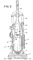
- FIGURE 2 is a front elevational view of the vacuum cleaner illustrated in FIGURE 1;
- FIGURES 3 and 4 are left and right side elevational views, respectively, of the vacuum cleaner shown in FIGURE 1;
- FIGURE 5 is a rear elevational view of the vacuum cleaner of FIGURE 1, further showing the required suction hose assemblies in broken lines for clarity;
- FIGURE 6 is a bottom plan view of the vacuum cleaner of FIGURE 1;
- FIGURE 7 is a front elevational view of the upright body portion of the vacuum cleaner of FIGURE 1;
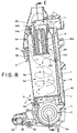
- FIGURE 8 is a partial side view in cross-section of the vacuum cleaner illustrated in FIGURE 1, and further diagrammatically illustrating the suction airstream flow;
- FIGURE 9 is a perspective view of the upright body portion shown in FIGURE 7, with the dirt cup and main filter housing removed for clarity;
- FIGURE 10 is an exploded perspective view of the main filter, main filter housing, and dirt cup;
- FIGURE 11 is a perspective view of the final filter assembly in accordance with the present invention;
- FIGURES 12A and 12B are rear elevational and bottom plan views, respectively, of the upper portion of the main filter housing;
- FIGURE 13A is a perspective view of a main filter in accordance with the present invention;
- FIGURE 13B is a bottom plan view of the main filter;
- FIGURE 13C is a cross-sectional view of the main filter along line C-C of FIGURE 13B;
- FIGURE 13D is a cross-sectional view of an alternative main filter element in accordance with the present invention; and,
- FIGURE 14 is a front elevational view, partially in cross-section along line E-E of FIGURE 8, illustrating the upright body portion of the vacuum cleaner of FIGURE 1.
- Referring now to the FIGURES, wherein the showings are for purposes of illustrating preferred embodiments of the invention only and not for purposes of limiting the same, FIGURES 1-6 illustrate an upright vacuum cleaner A including an upright housing section B and a nozzle base section C. The sections B,C are pivotally or hingedly connected through the use of trunnions or another suitable hinge assembly D so that the upright housing section B pivots between a generally vertical storage position (as shown) and an inclined operative position. Both the upright and nozzle sections B,C are preferably made from conventional materials such as molded plastics and the like. The upright section B includes a
handle 20 extending upward therefrom by which an operator of the vacuum A is able to grasp and maneuver the vacuum. - During vacuuming operations, the nozzle base C travels across the floor, carpet, or other subjacent surface being cleaned. The underside 24 (FIGURE 6) of the nozzle includes a main suction opening 26 formed therein which extends substantially across the width of the nozzle at the front end thereof. The main suction opening 26 is in fluid communication with the vacuum upright body section B through a
passage 30 and a connector hose assembly 34 (FIGURE 5). A rotatingbrush assembly 36 is positioned in the region of the nozzle main suction opening 26 for contacting and scrubbing the surface being vacuumed to loosen embedded dirt and dust. A plurality ofwheels 38 support the nozzle on the surface being cleaned and facilitate its movement thereacross. - The upright vacuum cleaner A includes a vacuum or suction source for generating the required suction airflow for cleaning operations. With reference particularly to FIGURES 5 and 9, a suitable suction source, such as an electric motor and fan assembly E, generates a suction force in a
suction inlet 40 an exhaust force in anexhaust outlet 42. The motor assemblyairflow exhaust outlet 42 is in fluid communication with a final filter assembly F for filtering the exhaust airstream of any contaminants immediately prior to its discharge into the atmosphere. The motorassembly suction inlet 40, on the other hand, is in fluid communication with anelongated suction conduit 46 which extends upward from the motor/fan assembly E to an upper region of the upright section B where it communicates with the cyclonic suction airflow dust and dirt separating region G of the vacuum A to generate a suction force therein. - With reference particularly to FIGURES 7 and 8, the cyclonic suction airflow dust and dirt separating region G housed in the upright section B includes a main
filter housing assembly 50 and a mating dust and dirt cup orcontainer 52. Thesections cyclonic airflow chamber 54. - It may be seen with reference also to FIGURE 10 that the main
filter housing assembly 50 is, itself, constructed from two mating sections - an upper fixedhousing section 50a, and a lower, detachablefilter housing section 50b. The lower detachablefilter housing section 50b receives and retains a main filter element or cartridge H. Thefilter housing section 50b releasably connects with theupper housing section 50a to secure the filter element H in an operative filtering position. More particularly, thesection 50b includes a plurality of tabs ortangs 54b extending therefrom. Likewise, with reference also to FIGURE 12B, it is shown that theupper housing section 50a includes mating tabs ortangs 54a. Thus, those skilled in the art will recognize that thecomponents filter housing section 50b in relation to theupper housing section 50a so that a filter element H is operatively secured in position. Of course, rather than themating tabs housing sections filter housing section 50b includes a plurality of apertures, slots, orother passages 56 formed therethrough, preferably in the lower half thereof, so that the suction airstream flows freely from thechamber 54 into thefilter housing section 50b and to the main filter element H. - The housing
upper section 50a includes a suction airflow outlet passage 60 (FIGURE 8) which communicates with thecyclonic chamber 54 through anaperture 62. Theoutlet passage 60 also communicates with theelongated suction conduit 46 leading to the motor/fan assembly E when the mainfilter housing assembly 50 is operatively connected to the vacuum upright section B. FIGURES 8 and 9 show that theelongated suction conduit 46 extends from the motor/fan assembly E upward to communicate with the main filter housingsuction outlet passage 60 so that the suction inlet of the motor/fan assembly E is able to fluidically communicate with thecyclonic chamber 54. When the mainfilter housing assembly 50 is assembled and in the operative position as described, a mouth 66 (FIGURE 10) of the filter element H mates with the periphery of theaperture 62 in a fluid-tight relationship. As such, the suction airflow from thecyclonic chamber 54 to the motor/fanassembly suction inlet 42 is not able to bypass the main filter element H, but instead must pass therethrough and be filtered of residual contaminants. It is preferable that theaperture 62, and thus the main filter element H be centrally located in thecyclonic chamber 54 to facilitate the cyclonic airflow in the chamber. - The suction airstream enters an upper portion of the cyclonic dust and
dirt separation chamber 54 through a generally tangentialsuction airstream inlet 80. In the preferred embodiment, as shown in FIGURES 12A-12B, the cyclonicchamber airstream inlet 80 is formed in theupper section 50a of the mainfilter housing assembly 50. It is noted that theinlet 80 is disposed entirely on one side of acenter line 81 of the upper housing section so as to induce a swirling flow around thefilter housing section 50b. Thesuction airstream inlet 80 of thechamber 54 is in fluid communication with asuction airstream hose 82 through a fitting 84. As shown in FIGURE 5, thehoses nozzle underside 24 is in fluid communication with thecyclonic chamber 54 through thepassage 30, thehoses chamber suction inlet 80. - The
dirt container 52 of the cyclonic airflow dust and dirt separating assembly G is constructed for large capacity and ease of emptying the contents as necessary. In FIGURE 8, it may be seen that thedirt container 52 defines over ½ the volume of thecyclonic chamber 54. As such, the capacity of thecontainer 52 is maximized to lengthen the operational time before thedirt container 52 must be emptied. - The
dirt container 52 is connected to the vacuum upright section B through use of ahinge 90 which allows thedirt container 52 to pivot as indicated by the arrow I between an operative upright position and an open forwardly tilted position. As shown herein, thehinge 90 comprises afirst component 92 connected to thedirt container 52 and asecond mating component 94 formed on the upright section B. Once thedirt container 52 is pivoted to the open position, it may be pulled upward and away from the section B and separated therefrom for ease of emptying the dirt container. Of course, after the dirt container is emptied, the foregoing procedure is reversed so that the dirt container is once again in the operative position. Ahandle 96 is provided on the exterior of thecontainer 52 to facilitate operator movement of the container between the operative, open, and removed position. A resiliently biasedlatch 98 retains the dirt container in the operative position. Thelatch 98 is biased through use of a spring or other resilient member, or via the natural resiliency of the plastic from which it is molded. - With continuing reference to FIGURE 8, the dirt container
upper edge 100 defining an open upper end of thecontainer 52 is preferably inclined downwardly in the direction away from thehandle 96 or front of thecontainer 52. The main filterhousing assembly section 50 is formed with a complimentary matinginclined edge 102, and a seal such as a gasket or other structure (not shown) is provided between the edges 100,102 to prevent air leakage into thecyclonic airflow chamber 54. The inclinedupper edge 100 of thedirt container 52 also ensures that, when the container is pivoted to the open position, theupper edge 100 lies in a substantially horizontal plane. As such, the contents of the container are much less likely to spill when the container is opened during emptying operations. Preferably, the angle at which theupper edge 100 is inclined from horizontal is selected, in combination with the maximum distance the container is able to be pivoted on the arc I when opened, such that when the container is fully opened, the upper edge lies in a substantially horizontal plane. - As is shown in FIGURES 13A-13C, the main filter element H is preferably generally frusto-conical in overall configuration, converging in the direction away from the
filter mouth 66 toward anopposite filter end 110. However, those skilled in the art will recognize that a cylindrical or other filter configuration may be advantageously employed without departing from the scope and overall intent of the invention. - The preferred filter media comprises Porex® brand high density polyethylene-based open-celled porous media available commercially from Porex Technologies Corp., Fairburn, Georgia 30213, or an equivalent foraminous filter media. This preferred filter media is a rigid open-celled foam that is moldable, machinable, and otherwise workable into any shape as deemed advantageous for a particular application. Most preferably, to optimize filtration but also to allow sufficient airflow rates, the preferred filter media has an average pore size in the range of 45µm to 90µm. As is shown in FIGURES 13A-13C, the filter H is most preferably formed in a convoluted or circuitous configuration to maximize an
outer surface area 112 of the filter. The maximizedsurface area 112 allows for the filter media to have a smaller pore size without unduly restricting the airflow therethrough. Most preferably, the filter media is formed into at least two elongated and concentric cylinders and/orfrustums annular passage 116 defined therebetween. Preferably, a deepcentral passage 118 is defined in the innermost cylinder orfrustum 114a. However, it should be appreciated that other filter designs could also be used if so desired. For example, it is possible to use a filter element not having a deep central passage. FIGURE 13D illustrates such an alternative configuration of the main filter element H'. Like components relative to the main filter element H are identified with like numerals including a primed (') suffix. The filter element H' is formed by concentriccylindrical portions 114a',114b' separated by a deep annular passage 116'. However, unlike the main filter element H, the element H' does not include a deep central passage formed in theinner cylinder 114a'. - As mentioned, the subject vacuum A also comprises a final filter assembly F for filtering the suction airstream downstream from the motor/fan assembly and immediately prior to its exhaustion into the atmosphere. The preferred final filter assembly F is illustrated most clearly in FIGURE 11 and comprises a
suction airstream inlet 120 which is connected in fluid communication with theexhaust outlet 42 of the motor and fan assemblyE. The inlet 120 is itself in fluid communication with anelongated plenum 122 that opens to the atmosphere and houses filter media. A protective grid or grate structure is snap-fit or otherwise effectively secured over theplenum 122 to secure the filter media in place. The filter media is preferably a high efficiency particulate arrest (HEPA) filter element in a sheet or block form. The filter media is retained in position in the plenum by thegrid 124, but is easily replaced by removing the grid. As such, those skilled in the art will recognize that even if the motor/fan assembly causes contaminants to be introduced into the suction airstream downstream from the main filter element H, the final filter assembly F will remove the same such that only contaminant-free air is discharged into the atmosphere. - Referring primarily to FIGURES 8 and 14, the operation of the vacuum cleaning apparatus A is illustrated, with the flow of the suction airstream indicated by use of arrows J. The motor/fan assembly E or other suction generator establishes a suction force at its
suction inlet 42, in theelongated suction conduit 46, and thus in thecyclonic separation chamber 54. This suction force or negative pressure in thechamber 54 is communicated to the main suction opening 26 formed in thenozzle underside 24 through thehoses 82,34 (FIGURE 5) and associated fittings. This, then, in combination with the scrubbing action of therotating brush assembly 36 causes dust and dirt from the surface being cleaned to be entrained in the suction airflow J and pulled into the upper portion of thechamber 54 through the generallytangential inlet 80. - The location of the
inlet 80, theoutlet passage 60, and the generally cylindrical configuration of thechamber 54 causes the suction airstream to follow a swirling or cyclonic path downward within thechamber 54 and then to move upward through a central portion of thechamber 54 toward the centrally located mainfilter housing section 50b. The orientation of theinlet 80 will affect the direction of cyclonic airflow, and the invention is not meant to be limited to a particular direction, i.e, clockwise or counterclockwise. Those skilled in the art will certainly recognize that the term "cyclonic" as used herein is not meant to be limited to a particular direction of airflow rotation. This cyclonic action separates a substantial portion of the entrained dust and dirt from the suction airstream and causes the dust and dirt to be deposited in the dirt cup orcontainer 52. The suction airstream then passes through theapertures 56 formed in the mainfilter housing section 50b, passes through the main filter element H so that residual contaminants are removed, and exits thecyclonic chamber 54 through the suctionairstream outlet passage 60 formed in the mainfilter housing section 50a. The suction airstream is communicated to the motor/fan assembly E and exhausted through the outlet 42 (as indicated by broken arrows) to the final filter assembly F where it is filtered again by the HEPA filter to remove any contaminants that passed through thechamber 54 and the filter H, and any contaminants in the airstream due to its passage through the motor/fan assembly E. - The main filter element H can be cleaned by washing it, either manually or in a dishwasher -- since it is dishwasher-safe -- to remove dust or dirt particles adhering to the filter element. It is, however, important that the filter H be dried before it is used again. The final filter media of the filter assembly F, however, can not be cleaned and must be replaced when it becomes clogged.
- The invention has been described with reference to the preferred embodiments. Obviously, modifications and alterations will occur to others upon reading and understanding the preceding detailed description. It is intended that the invention be construed as including all such modifications and alterations insofar as they come within the scope of the appended claims or the equivalents thereof.
Claims (13)
- An upright vacuum cleaner comprising:an upright housing section (B) includin a handle (20);a nozzle base section (C) hingedly interconnected with the upright housing section (B), said nozzle base section (C) including a main suction opening (26) formed in an underside thereof;a cyclonic airflow chamber (54) defined in said upright housing section (B) for separating dust and dirt from a suction airstream;a suction source (E) located in one of said upright housing section (B) and said nozzle base section (C) and having a suction airflow inlet (40) in fluid communication with said cyclonic chamber (54) and a suction airflow outlet (42), a lower portion of said cyclonic chamber (54) being defined by a dirt container (52) for receiving and retaining dust and dirt separated from said suction airstream; and,a final filter assembly (F) located on one of said housing and said nozzle base sections (B, C), said final filter assembly (F) being connected in fluid communication with said suction airflow outlet (42) of said suction source (E) for filtering said suction airstream exhausted by said suction source (E) prior to said suction airstream being dispersed into the atmosphere,characterized in that
a main filter assembly (50) with a main filter element (H) is located between said cyclonic chamber (54) and said suction source (E) for filtering residual dust and dirt from a suction airstream after said suction airstream passes through said cyclonic chamber (54), wherein said main filter element (H) includes a convoluted outer surface (112). - The vacuum cleaner as set forth in claim 1 wherein said final filter assembly (F) comprises a high efficiency particulate arrest (HEPA) filter media.
- The vacuum cleaner as set forth in claim 1 wherein said main filter assembly (50) comprises a filter element including porous high-density polyethylene foam filter media.
- The vacuum cleaner as set forth in claim 3 wherein said porous filter media has pores with an average pore size of less than approximately 90 µm.
- The vacuum cleaner as set forth in any of claims 1-4 wherein said convoluted outer surface (112) defines at least a first elongated inner filter section (114a) and a second elongated filter section (114b), wherein said first (114a) and second (114b) filter sections are separated by a deep airflow passage (116).
- The vacuum cleaner as set forth in claim 1 wherein said dirt container (52) is pivotable between an operative position and an open position and including an open upper end defined by an inclined edge (100) such that when said dirt container (52) is pivoted fully into the open position, the inclined edge (100) is located in a substantially horizontal plane to inhibit spillage of the separated dirt and dust.
- The vacuum cleaner as set forth in claim 1 wherein after separating dust and dirt from the suction airstream in the cyclonic chamber (54) the suction airstream flows into said upright housing section (B) between an inlet (80) located at the periphery of said upright housing section (B) and an outlet (60) located at an apex of said upright housing section (B), comprising a filter housing section (50b), the main filter element (H) and the filter housing section (50b) cooperating to define a tortuous flow path for air flowing from said cyclonic chamber (54) to said outlet (60) of said upright housing section (B).
- The vacuum cleaner as set forth in claim 1 wherein the main filter assembly includes cooperating fasteners for releasably connecting the filter housing section (50b) to an upper fixed housing section (50a).
- The upright vacuum cleaner of any of claims 1-8 wherein the main filter element (H) is located in the cyclonic airflow chamber (54).
- The upright vacuum cleaner of any of claims 1-9 wherein the suction source (E) is located in the upright housing section (B) below the dirt container (52).
- The upright vacuum cleaner of any of claims 1-10 further comprising a hinge (90) for pivotally mounting the dirt container (52) to the upright housing section (B).
- The upright vacuum cleaner of any of claims 1-11 wherein the dirt container (52) is retained by a latch (98).
- The upright vacuum cleaner of claim 12 wherein the latch is located adjacent the handle (96) of the dirt container.
Priority Applications (5)
| Application Number | Priority Date | Filing Date | Title |
|---|---|---|---|
| EP06000399A EP1661501B1 (en) | 1998-01-09 | 1998-03-17 | Upright vacuum cleaner with cyclonic airflow |
| PCT/US1998/021265 WO1999034722A1 (en) | 1998-01-09 | 1998-10-08 | Upright vacuum cleaner with cyclonic airflow |
| DE69841577T DE69841577D1 (en) | 1998-01-09 | 1998-10-08 | CINEMA VACUUM CYCLES WITH CYCLONE-TONE AIR FLOW |
| EP98952175A EP1052924B1 (en) | 1998-01-09 | 1998-10-08 | Upright vacuum cleaner with cyclonic airflow |
| AT98952175T ATE461647T1 (en) | 1998-01-09 | 1998-10-08 | HANDLE VACUUM CLEANER WITH CYCLONE-LIKE AIRFLOW |
Applications Claiming Priority (2)
| Application Number | Priority Date | Filing Date | Title |
|---|---|---|---|
| US4999 | 1987-01-20 | ||
| US09/004,999 US6003196A (en) | 1998-01-09 | 1998-01-09 | Upright vacuum cleaner with cyclonic airflow |
Related Child Applications (1)
| Application Number | Title | Priority Date | Filing Date |
|---|---|---|---|
| EP06000399A Division EP1661501B1 (en) | 1998-01-09 | 1998-03-17 | Upright vacuum cleaner with cyclonic airflow |
Publications (3)
| Publication Number | Publication Date |
|---|---|
| EP0928594A1 EP0928594A1 (en) | 1999-07-14 |
| EP0928594B1 true EP0928594B1 (en) | 2006-05-10 |
| EP0928594B8 EP0928594B8 (en) | 2006-09-06 |
Family
ID=21713606
Family Applications (2)
| Application Number | Title | Priority Date | Filing Date |
|---|---|---|---|
| EP06000399A Expired - Lifetime EP1661501B1 (en) | 1998-01-09 | 1998-03-17 | Upright vacuum cleaner with cyclonic airflow |
| EP98104806A Expired - Lifetime EP0928594B8 (en) | 1998-01-09 | 1998-03-17 | Upright vacuum cleaner with cyclonic airflow |
Family Applications Before (1)
| Application Number | Title | Priority Date | Filing Date |
|---|---|---|---|
| EP06000399A Expired - Lifetime EP1661501B1 (en) | 1998-01-09 | 1998-03-17 | Upright vacuum cleaner with cyclonic airflow |
Country Status (5)
| Country | Link |
|---|---|
| US (7) | US6003196A (en) |
| EP (2) | EP1661501B1 (en) |
| AT (3) | ATE405203T1 (en) |
| DE (3) | DE69834473T2 (en) |
| ES (2) | ES2262201T3 (en) |
Families Citing this family (233)
| Publication number | Priority date | Publication date | Assignee | Title |
|---|---|---|---|---|
| US6735817B2 (en) * | 1998-01-09 | 2004-05-18 | Royal Appliance Mfg. Co. | Upright vacuum cleaner with cyclonic air flow |
| US6003196A (en) * | 1998-01-09 | 1999-12-21 | Royal Appliance Mfg. Co. | Upright vacuum cleaner with cyclonic airflow |
| US6070291A (en) * | 1998-01-09 | 2000-06-06 | Royal Appliance Mfg. Co. | Upright vacuum cleaner with cyclonic air flow |
| WO1999034722A1 (en) | 1998-01-09 | 1999-07-15 | Royal Appliance Mfg. Co. | Upright vacuum cleaner with cyclonic airflow |
| USD433201S (en) * | 1999-01-06 | 2000-10-31 | Royal Appliance Mfg. Co. | Vacuum cleaner dust cup |
| US6238451B1 (en) | 1999-01-08 | 2001-05-29 | Fantom Technologies Inc. | Vacuum cleaner |
| US6782585B1 (en) * | 1999-01-08 | 2004-08-31 | Fantom Technologies Inc. | Upright vacuum cleaner with cyclonic air flow |
| US6334234B1 (en) * | 1999-01-08 | 2002-01-01 | Fantom Technologies Inc. | Cleaner head for a vacuum cleaner |
| USD429854S (en) * | 1999-02-16 | 2000-08-22 | White Consolidated Industries, Inc. | Upright vacuum cleaner |
| USD434884S (en) * | 1999-02-16 | 2000-12-05 | White Consolidated Industries, Inc. | Upright vacuum cleaner |
| JP3476066B2 (en) * | 1999-07-19 | 2003-12-10 | シャープ株式会社 | Electric vacuum cleaner |
| JP2001037687A (en) * | 1999-08-02 | 2001-02-13 | Matsushita Electric Ind Co Ltd | Vacuum cleaner |
| US6484350B2 (en) | 1999-12-08 | 2002-11-26 | Shell Electric Mfg. (Holdings) Co. Ltd. | Bagless canister vacuum cleaner |
| US6269518B1 (en) | 1999-12-08 | 2001-08-07 | Shell Electric Mfg. (Holdings) Co. Ltd. | Bagless vacuum cleaner |
| US6341404B1 (en) | 2000-01-13 | 2002-01-29 | Royal Appliance Mfg. Co. | Upright vacuum cleaner with cyclonic airflow pathway |
| US6910245B2 (en) * | 2000-01-14 | 2005-06-28 | White Consolidated Industries, Inc. | Upright vacuum cleaner with cyclonic air path |
| US6558453B2 (en) | 2000-01-14 | 2003-05-06 | White Consolidated Industries, Inc. | Bagless dustcup |
| US8412377B2 (en) | 2000-01-24 | 2013-04-02 | Irobot Corporation | Obstacle following sensor scheme for a mobile robot |
| US6596044B1 (en) | 2000-03-06 | 2003-07-22 | The Hoover Company | Dirt collecting system for a vacuum cleaner |
| US6956348B2 (en) | 2004-01-28 | 2005-10-18 | Irobot Corporation | Debris sensor for cleaning apparatus |
| US20030159411A1 (en) * | 2000-05-05 | 2003-08-28 | Bissell Homecare, Inc. | Cyclonic dirt separation module |
| US6616722B1 (en) | 2000-05-09 | 2003-09-09 | Hmi Industries, Inc. | Room air cleaner |
| FR2808988B1 (en) * | 2000-05-16 | 2002-07-19 | Seb Sa | WASTE COLLECTOR FOR VACUUM CLEANER |
| KR100437156B1 (en) * | 2000-05-16 | 2004-06-25 | 삼성광주전자 주식회사 | Upright-type vacuum cleaner having cyclone dust-collecting apparatus |
| KR100437155B1 (en) * | 2000-05-16 | 2004-06-25 | 삼성광주전자 주식회사 | Upright-type vacuum cleaner having cyclone dust-collecting apparatus |
| GB2362341B (en) | 2000-05-16 | 2002-12-04 | Samsung Kwangju Electronics Co | Upright-type vacuum cleaner |
| AU754573B2 (en) | 2000-06-16 | 2002-11-21 | Samsung Gwangju Electronics Co., Ltd. | Upright-type vacuum cleaner having a cyclone dust collecting apparatus |
| KR100437368B1 (en) * | 2000-06-16 | 2004-06-25 | 삼성광주전자 주식회사 | Upright-type vacuum cleaner having cyclone dust-collecting apparatus |
| GB2368269B (en) * | 2000-06-16 | 2002-12-18 | Samsung Kwangju Electronics Co | Upright-type vacuum cleaner having a cyclone dust collecting apparatus |
| KR100437366B1 (en) * | 2000-06-24 | 2004-06-25 | 삼성광주전자 주식회사 | Upright-type vacuum cleaner having cyclone dust-collecting apparatus |
| KR100437367B1 (en) * | 2000-06-24 | 2004-06-25 | 삼성광주전자 주식회사 | Upright-type vacuum cleaner having cyclone dust-collecting apparatus |
| KR100377015B1 (en) | 2000-08-07 | 2003-03-26 | 삼성광주전자 주식회사 | Cyclone dust-collecting apparatus for Vacuum Cleaner |
| JP3442351B2 (en) * | 2000-08-09 | 2003-09-02 | シャープ株式会社 | Electric vacuum cleaner |
| US6712868B2 (en) | 2000-09-01 | 2004-03-30 | Royal Appliance Mfg. Co. | Bagless canister vacuum cleaner |
| GB2373997B (en) * | 2000-10-03 | 2004-07-21 | Matsushita Electric Corp | Airflow system for bagless vacuum cleaner |
| GB2367484B (en) * | 2000-10-07 | 2004-10-27 | Hoover Ltd | Vacuum cleaner with 2-stage separation |
| KR100377016B1 (en) * | 2000-10-19 | 2003-03-26 | 삼성광주전자 주식회사 | Upright type Vacuum Cleaner |
| US6485536B1 (en) | 2000-11-08 | 2002-11-26 | Proteam, Inc. | Vortex particle separator |
| KR100437369B1 (en) * | 2001-01-10 | 2004-06-25 | 삼성광주전자 주식회사 | Cyclone dust-collecting apparatus for Vacuum Cleaner |
| KR100437363B1 (en) * | 2001-01-11 | 2004-06-25 | 삼성광주전자 주식회사 | Locking apparatus for dust barrel of cyclone dust-collecting apparatus |
| US6436160B1 (en) | 2001-01-11 | 2002-08-20 | Royal Appliance Mfg. Co. | Dirt cup assembly for vacuum cleaner |
| KR100406639B1 (en) | 2001-01-11 | 2003-11-21 | 삼성광주전자 주식회사 | Upright typed vacuum cleaner |
| US6532621B2 (en) * | 2001-01-12 | 2003-03-18 | Royal Appliance Mfg. Co. | Vacuum cleaner with noise suppression features |
| JP3635657B2 (en) | 2001-01-22 | 2005-04-06 | ツインバード工業株式会社 | Cyclone vacuum cleaner |
| US6690134B1 (en) | 2001-01-24 | 2004-02-10 | Irobot Corporation | Method and system for robot localization and confinement |
| US7571511B2 (en) | 2002-01-03 | 2009-08-11 | Irobot Corporation | Autonomous floor-cleaning robot |
| US6511531B1 (en) | 2001-01-26 | 2003-01-28 | Hmi Industries, Inc. | Room air filtering and freshening device |
| US7143469B2 (en) * | 2001-02-06 | 2006-12-05 | The Hoover Company | Dirt collecting system |
| GB2372431B (en) * | 2001-02-24 | 2004-09-15 | Dyson Ltd | A domestic appliance |
| US6488744B2 (en) | 2001-03-19 | 2002-12-03 | Hmi Industries, Inc. | Filter system |
| CA2342993A1 (en) * | 2001-03-30 | 2002-09-30 | Fantom Technologies Inc. | Air cleaner with washable filter |
| US7185234B1 (en) * | 2001-04-30 | 2007-02-27 | Mips Technologies, Inc. | Trace control from hardware and software |
| KR100412580B1 (en) | 2001-06-04 | 2003-12-31 | 삼성광주전자 주식회사 | Upright-type vacuum cleaner |
| US7429843B2 (en) | 2001-06-12 | 2008-09-30 | Irobot Corporation | Method and system for multi-mode coverage for an autonomous robot |
| KR100398686B1 (en) * | 2001-07-25 | 2003-09-19 | 삼성광주전자 주식회사 | Cyclone dust collecting apparatus and upright-type Vacuum Cleaner |
| KR100412583B1 (en) * | 2001-07-28 | 2003-12-31 | 삼성광주전자 주식회사 | Vaccum cleaner |
| EP1283021B1 (en) * | 2001-08-08 | 2010-09-22 | Panasonic Corporation | Vacuum cleaner comprising dirt compressing means |
| US6687952B1 (en) | 2002-01-07 | 2004-02-10 | Hmi Industries, Inc. | Wet vacuum cleaner attachment for vacuum cleaners |
| US6775882B2 (en) * | 2002-01-11 | 2004-08-17 | Royal Appliance Mfg. Co. | Stick vacuum with dirt cup |
| KR100433407B1 (en) * | 2002-02-06 | 2004-05-31 | 삼성광주전자 주식회사 | Upright-type vacuum cleaner |
| JP4021686B2 (en) * | 2002-03-04 | 2007-12-12 | ツインバード工業株式会社 | Cyclone vacuum cleaner |
| US6829804B2 (en) * | 2002-03-26 | 2004-12-14 | White Consolidated, Ltd. | Filtration arrangement of a vacuum cleaner |
| US7018438B2 (en) * | 2002-03-29 | 2006-03-28 | Hmi Industries, Inc. | Filtering system |
| KR100478641B1 (en) * | 2002-06-04 | 2005-03-24 | 삼성광주전자 주식회사 | Cyclone-type dust collect apparatus for vacuum cleaner |
| GB2391459A (en) * | 2002-08-09 | 2004-02-11 | Dyson Ltd | A surface treating appliance with increased manoeuverability |
| US6951045B2 (en) * | 2002-08-20 | 2005-10-04 | Royal Appliance Mfg. Co. | Vacuum cleaner having hose detachable at nozzle |
| US8428778B2 (en) | 2002-09-13 | 2013-04-23 | Irobot Corporation | Navigational control system for a robotic device |
| KR100883198B1 (en) * | 2002-09-16 | 2009-02-13 | 삼성광주전자 주식회사 | Convertible vacuum cleaner |
| US6896719B2 (en) * | 2002-09-26 | 2005-05-24 | The Hoover Company | Dirt collecting system for a floor care appliance |
| KR100476426B1 (en) * | 2002-10-08 | 2005-03-16 | 엘지전자 주식회사 | Dust and dirt collecting unit for vacuum cleaner |
| US7260867B2 (en) * | 2002-10-11 | 2007-08-28 | Panasonic Corporation Of North America | Bagless dust box for vacuum cleaner |
| US7231688B2 (en) * | 2002-10-18 | 2007-06-19 | Panasonic Corporation Of North America | Dirt cup for vacuum cleaner |
| US7272871B1 (en) * | 2002-10-18 | 2007-09-25 | Panasonic Corporation Of North America | Dirt vessel equipped with cleaning plunger |
| KR100456167B1 (en) * | 2002-11-22 | 2004-11-09 | 삼성광주전자 주식회사 | Dust collecting filter for vacuum cleaner and vacuum cleaner having the same |
| US7331083B2 (en) * | 2002-12-18 | 2008-02-19 | Panasonic Corporation Of North America | Lighted wand assembly with remote light source |
| US20040134022A1 (en) * | 2003-01-10 | 2004-07-15 | Royal Manufacturing Co. | Bagless stick type vacuum cleaner |
| GB0307929D0 (en) * | 2003-04-05 | 2003-05-14 | Hoover Ltd | Vacuum cleaner |
| US7360275B2 (en) * | 2003-04-17 | 2008-04-22 | Allgeier David M | Dirt separation system for a vacuum cleaner |
| KR100587099B1 (en) * | 2003-05-10 | 2006-06-07 | 엘지전자 주식회사 | Dust removing unit of cyclone cleaner |
| US20040259100A1 (en) * | 2003-06-20 | 2004-12-23 | Illumina, Inc. | Methods and compositions for whole genome amplification and genotyping |
| KR100474079B1 (en) * | 2003-06-26 | 2005-03-14 | 삼성광주전자 주식회사 | Upright type vacuum cleaner |
| KR100564450B1 (en) * | 2003-07-09 | 2006-03-29 | 엘지전자 주식회사 | Mounting Structure of dust filtering unit in vacuum cleaner |
| WO2005009192A2 (en) | 2003-07-22 | 2005-02-03 | Panasonic Corporation Of North America | Bagless vacuum cleaner system |
| US7544224B2 (en) * | 2003-08-05 | 2009-06-09 | Electrolux Home Care Products, Inc. | Cyclonic vacuum cleaner |
| US7210196B2 (en) * | 2003-08-29 | 2007-05-01 | Panasonic Corporation Of North America | Bagless vacuum cleaner and dirt collection assembly |
| US7293324B2 (en) * | 2003-09-19 | 2007-11-13 | Techtronic Industries Co., Ltd. | Vacuum cleaner with level control |
| US20050060835A1 (en) * | 2003-09-20 | 2005-03-24 | Yasushi Kondo | Bagless vacuum cleaner and dust container assembly |
| US7332890B2 (en) | 2004-01-21 | 2008-02-19 | Irobot Corporation | Autonomous robot auto-docking and energy management systems and methods |
| JP2005204880A (en) * | 2004-01-22 | 2005-08-04 | Sanyo Electric Co Ltd | Vacuum cleaner and its dust collector |
| US7779506B2 (en) * | 2004-03-11 | 2010-08-24 | Lg Electronics Inc. | Vacuum cleaner |
| US7779507B2 (en) * | 2004-03-11 | 2010-08-24 | Lg Electronics Inc. | Vacuum cleaner |
| US20050198771A1 (en) * | 2004-03-11 | 2005-09-15 | Lg Electronics Inc. | Vacuum cleaner |
| US7669282B2 (en) * | 2004-03-11 | 2010-03-02 | Lg Electronics Inc. | Vacuum cleaner |
| US7329295B2 (en) * | 2004-03-17 | 2008-02-12 | Euro-Pro Operating, Llc | Light weight bagless vacuum cleaner |
| US7341611B2 (en) | 2004-03-17 | 2008-03-11 | Euro-Pro Operating, Llc | Compact cyclonic bagless vacuum cleaner |
| JP2008508572A (en) | 2004-06-24 | 2008-03-21 | アイロボット コーポレーション | Portable robot programming and diagnostic tools |
| US8972052B2 (en) | 2004-07-07 | 2015-03-03 | Irobot Corporation | Celestial navigation system for an autonomous vehicle |
| US7706917B1 (en) | 2004-07-07 | 2010-04-27 | Irobot Corporation | Celestial navigation system for an autonomous robot |
| US7287300B2 (en) * | 2004-07-09 | 2007-10-30 | Nss Enterprises, Inc. | Portable vacuum system |
| KR100936065B1 (en) | 2004-07-22 | 2010-01-12 | 엘지전자 주식회사 | A dust collector for vacuum cleaner |
| WO2006026414A2 (en) | 2004-08-26 | 2006-03-09 | Euro-Pro Operating, Llc | Cyclonic separation device for a vacuum cleaner |
| KR20060019739A (en) * | 2004-08-30 | 2006-03-06 | 엘지전자 주식회사 | A structure of suction nozzle in vacuum cleaner |
| GB2417702B (en) * | 2004-09-01 | 2007-10-24 | Bissell Homecare Inc | Cyclone separator with fine particle separation member |
| KR100601895B1 (en) * | 2004-11-16 | 2006-07-19 | 삼성광주전자 주식회사 | Cyclon type vacuum cleaner |
| KR200377056Y1 (en) * | 2004-12-08 | 2005-03-10 | 엘지전자 주식회사 | Dust and dirt collecting unit for vacuum cleaner |
| KR100871484B1 (en) * | 2004-12-14 | 2008-12-05 | 엘지전자 주식회사 | Dust and dirt Collecting unit for vacuum Cleaner |
| KR100560967B1 (en) | 2005-01-14 | 2006-03-15 | 삼성광주전자 주식회사 | A cyclone dust-separating apparatus |
| EP2279686B1 (en) | 2005-02-18 | 2012-11-14 | iRobot Corporation | Autonomous surface cleaning robot for wet and dry cleaning |
| US7620476B2 (en) | 2005-02-18 | 2009-11-17 | Irobot Corporation | Autonomous surface cleaning robot for dry cleaning |
| US8392021B2 (en) * | 2005-02-18 | 2013-03-05 | Irobot Corporation | Autonomous surface cleaning robot for wet cleaning |
| US8930023B2 (en) | 2009-11-06 | 2015-01-06 | Irobot Corporation | Localization by learning of wave-signal distributions |
| KR100594584B1 (en) * | 2005-04-22 | 2006-06-30 | 삼성광주전자 주식회사 | Filter assembly and cyclone dust collecting apparatus having the same |
| JP2006320713A (en) * | 2005-05-16 | 2006-11-30 | Samsung Kwangju Electronics Co Ltd | Multi-cyclone dust collector |
| GB2427999A (en) * | 2005-07-07 | 2007-01-17 | Hoover Ltd | Vacuum cleaner providing filter-absence detection |
| GB2466896B (en) * | 2005-07-12 | 2010-08-25 | Bissell Homecare Inc | Vacuum cleaner base |
| US20070028413A1 (en) * | 2005-08-03 | 2007-02-08 | Fischer Richard J | Upright vacuum cleaner with removable air path cover for canister assembly |
| ES2623920T3 (en) | 2005-12-02 | 2017-07-12 | Irobot Corporation | Robot system |
| KR101300493B1 (en) | 2005-12-02 | 2013-09-02 | 아이로보트 코퍼레이션 | Coverage robot mobility |
| KR101099808B1 (en) | 2005-12-02 | 2011-12-27 | 아이로보트 코퍼레이션 | Robot system |
| ATE442619T1 (en) | 2005-12-02 | 2009-09-15 | Irobot Corp | MODULAR ROBOT |
| US20070163075A1 (en) * | 2006-01-17 | 2007-07-19 | Butler Dennis C | Stair cleaning vacuum cleaner |
| US20070163073A1 (en) * | 2006-01-19 | 2007-07-19 | Arnold Sepke | Vacuum cleaner dustcup and conduit construction |
| US20070174993A1 (en) * | 2006-02-02 | 2007-08-02 | Dever Kerry L | Filter cleaning system for floor cleaning apparatus |
| US20070209150A1 (en) * | 2006-03-08 | 2007-09-13 | Gogel Nathan A | Floor cleaning apparatus with filter cleaning system |
| US7908707B2 (en) * | 2006-03-08 | 2011-03-22 | Panasonic Corporation Of North America | Floor cleaning apparatus with filter cleaning system |
| CA2581795C (en) * | 2006-03-08 | 2010-02-09 | Panasonic Corporation Of North America | Vacuum cleaner with wand activated conversion valve |
| US7749293B2 (en) * | 2006-03-10 | 2010-07-06 | G.B.D. Corp. | Vacuum cleaner with a removable cyclone array |
| GB2436308A (en) | 2006-03-23 | 2007-09-26 | Adrian Christopher Arnold | Particle separator |
| US8087117B2 (en) | 2006-05-19 | 2012-01-03 | Irobot Corporation | Cleaning robot roller processing |
| US8417383B2 (en) | 2006-05-31 | 2013-04-09 | Irobot Corporation | Detecting robot stasis |
| WO2007141523A1 (en) | 2006-06-08 | 2007-12-13 | Dyson Technology Limited | Cleaning and /or filtering apparatus |
| US7581287B2 (en) * | 2006-06-14 | 2009-09-01 | Panasonic Corporation Of North America | Vacuum cleaner with spiral air guide |
| GB2441300B (en) * | 2006-09-01 | 2011-10-12 | Dyson Technology Ltd | A collecting chamber for a vacuum cleaner |
| US7749292B2 (en) * | 2006-11-16 | 2010-07-06 | Suzhou Clean Bloom Electric Co., Ltd. | Cyclonic dust collecting apparatus |
| CA2658372C (en) | 2009-03-13 | 2016-09-27 | G.B.D. Corp. | Surface cleaning apparatus |
| US8621709B2 (en) * | 2006-12-12 | 2014-01-07 | G.B.D. Corp. | Multi-strut cleaning head |
| US8950039B2 (en) | 2009-03-11 | 2015-02-10 | G.B.D. Corp. | Configuration of a surface cleaning apparatus |
| CN101657133A (en) | 2006-12-12 | 2010-02-24 | Gbd公司 | Surface cleaning apparatus |
| US10765277B2 (en) | 2006-12-12 | 2020-09-08 | Omachron Intellectual Property Inc. | Configuration of a surface cleaning apparatus |
| WO2008109984A1 (en) * | 2007-03-09 | 2008-09-18 | Gbd Corp. | Upright surface cleaning apparatus with offset motor |
| US7744683B2 (en) * | 2007-04-23 | 2010-06-29 | Yuejie Zhang | Transparent filterable dust bag with support container for vacuum cleaner |
| KR101414321B1 (en) | 2007-05-09 | 2014-07-01 | 아이로보트 코퍼레이션 | Autonomous coverage robot |
| KR20080102647A (en) * | 2007-05-21 | 2008-11-26 | 삼성광주전자 주식회사 | Cyclone dust-separating unit for use in a vacuum cleaner |
| US11751733B2 (en) | 2007-08-29 | 2023-09-12 | Omachron Intellectual Property Inc. | Portable surface cleaning apparatus |
| SE531908C2 (en) * | 2008-01-16 | 2009-09-08 | Electrolux Ab | Vacuum cleaner |
| USD626708S1 (en) | 2008-03-11 | 2010-11-02 | Royal Appliance Mfg. Co. | Hand vacuum |
| US8069529B2 (en) * | 2008-10-22 | 2011-12-06 | Techtronic Floor Care Technology Limited | Handheld vacuum cleaner |
| US20100132317A1 (en) * | 2008-11-21 | 2010-06-03 | Thien J Philip | Dust separator |
| US11612288B2 (en) | 2009-03-13 | 2023-03-28 | Omachron Intellectual Property Inc. | Surface cleaning apparatus |
| US9226633B2 (en) | 2009-03-13 | 2016-01-05 | Omachron Intellectual Property Inc. | Surface cleaning apparatus |
| US9427122B2 (en) | 2009-03-13 | 2016-08-30 | Omachron Intellectual Property Inc. | Surface cleaning apparatus |
| US11690489B2 (en) | 2009-03-13 | 2023-07-04 | Omachron Intellectual Property Inc. | Surface cleaning apparatus with an external dirt chamber |
| CA2674376A1 (en) | 2009-03-13 | 2010-09-13 | G.B.D. Corp. | Surface cleaning apparatus with different cleaning configurations |
| US9480373B2 (en) | 2009-03-13 | 2016-11-01 | Omachron Intellectual Property Inc. | Surface cleaning apparatus |
| CA2674761C (en) | 2009-03-13 | 2016-10-04 | G.B.D. Corp. | Surface cleaning apparatus with different cleaning configurations |
| US9198551B2 (en) | 2013-02-28 | 2015-12-01 | Omachron Intellectual Property Inc. | Surface cleaning apparatus |
| US9211044B2 (en) | 2011-03-04 | 2015-12-15 | Omachron Intellectual Property Inc. | Compact surface cleaning apparatus |
| US9392916B2 (en) | 2009-03-13 | 2016-07-19 | Omachron Intellectual Property Inc. | Surface cleaning apparatus |
| US9138114B2 (en) | 2009-03-13 | 2015-09-22 | Omachron Intellectual Property Inc. | Surface cleaning apparatus |
| US9591953B2 (en) | 2009-03-13 | 2017-03-14 | Omachron Intellectual Property Inc. | Surface cleaning apparatus |
| KR101317125B1 (en) | 2009-03-31 | 2013-10-08 | 다이슨 테크놀러지 리미티드 | A separating apparatus |
| US8167964B2 (en) * | 2009-04-09 | 2012-05-01 | Lau Ying Wai | Cyclonic chamber for air filtration devices |
| GB2469454C (en) * | 2009-04-14 | 2016-04-27 | Dyson Technology Ltd | A cleaner head |
| CN102470304B (en) | 2009-07-22 | 2016-01-20 | 唐纳森公司 | PTFE film and carbon mesh sheet is used to be used for the filter medium structure of HEPA efficiency and smell control |
| GB2472098B (en) | 2009-07-24 | 2014-05-28 | Dyson Technology Ltd | An electrostatic filter |
| GB2472097B (en) | 2009-07-24 | 2013-04-17 | Dyson Technology Ltd | Separating apparatus with electrostatic filter |
| GB2472095A (en) * | 2009-07-24 | 2011-01-26 | Dyson Technology Ltd | Vacuum cleaner with cyclone and electrostatic filter arrangement |
| GB2472096B (en) * | 2009-07-24 | 2013-04-17 | Dyson Technology Ltd | Separating apparatus with electrostatic filter |
| GB2474469B (en) * | 2009-10-15 | 2013-11-13 | Dyson Technology Ltd | A surface treating appliance |
| GB2474462B (en) | 2009-10-15 | 2013-12-11 | Dyson Technology Ltd | A surface treating appliance with domed-shaped wheels |
| GB2474468B (en) * | 2009-10-15 | 2013-11-27 | Dyson Technology Ltd | A surface treating appliance |
| GB2474475B (en) * | 2009-10-15 | 2013-10-23 | Dyson Technology Ltd | A surface treating appliance |
| GB2474470B (en) * | 2009-10-15 | 2013-10-23 | Dyson Technology Ltd | A surface treating appliance |
| GB2474464B (en) * | 2009-10-15 | 2013-11-20 | Dyson Technology Ltd | A surface treating appliance |
| GB2474471B (en) * | 2009-10-15 | 2013-10-23 | Dyson Technology Ltd | A surface treating appliance |
| GB2474466B (en) * | 2009-10-15 | 2014-03-05 | Dyson Technology Ltd | A surface treating appliance |
| GB2474473B (en) * | 2009-10-15 | 2013-10-23 | Dyson Technology Ltd | A surface treating appliance |
| GB2474463B (en) * | 2009-10-15 | 2013-11-13 | Dyson Technology Ltd | A surface treating appliance |
| GB2474465B (en) * | 2009-10-15 | 2013-10-23 | Dyson Technology Ltd | A surface treating appliance |
| GB0918027D0 (en) * | 2009-10-15 | 2009-12-02 | Dyson Technology Ltd | A surface trating appliance |
| GB2474472B (en) * | 2009-10-15 | 2013-10-23 | Dyson Technology Ltd | A surface treating appliance |
| CN102639207B (en) * | 2009-11-13 | 2015-03-11 | 埃克森美孚化学专利公司 | Fluid separation systems and methods |
| US8375508B2 (en) * | 2010-03-12 | 2013-02-19 | G.B.D. Corp. | Torque balancer for a surface cleaning head |
| US8152877B2 (en) | 2010-03-12 | 2012-04-10 | Euro-Pro Operating Llc | Shroud for a cleaning service apparatus |
| US8296900B2 (en) * | 2010-03-12 | 2012-10-30 | G.B.D. Corp. | Seal construction for a surface cleaning apparatus |
| US8875340B2 (en) | 2010-03-12 | 2014-11-04 | G.B.D. Corp. | Surface cleaning apparatus with enhanced operability |
| JP5669947B2 (en) | 2010-10-01 | 2015-02-18 | エンパイア テクノロジー ディベロップメント エルエルシー | Cyclone catalyst duct |
| US20120186203A1 (en) * | 2011-01-25 | 2012-07-26 | General Electric Company | Folded baghouse filter |
| US20130133155A1 (en) * | 2011-11-28 | 2013-05-30 | Julio C. Perez | Vacuum cleaner incorporating noise suppression system |
| DE102011087439A1 (en) * | 2011-11-30 | 2013-06-06 | BSH Bosch und Siemens Hausgeräte GmbH | Flow channel with dust separation |
| CN104114265A (en) | 2012-01-27 | 2014-10-22 | 宙斯工业产品股份有限公司 | Electrospun Porous Media |
| US9149165B2 (en) * | 2012-03-08 | 2015-10-06 | Bissell Homecare, Inc. | Vacuum cleaner and vacuum cleaner system |
| AU2013228064B2 (en) | 2012-09-26 | 2017-11-23 | Bissell Inc. | Vacuum cleaner |
| EP2916705B1 (en) | 2012-11-09 | 2020-06-03 | Aktiebolaget Electrolux | Cyclone dust separator arrangement, cyclone dust separator and cyclone vacuum cleaner |
| US9155433B2 (en) | 2012-11-27 | 2015-10-13 | Panasonic Corporation Of North America | Floor cleaning apparatus with filter drawer |
| US9282867B2 (en) | 2012-12-28 | 2016-03-15 | Irobot Corporation | Autonomous coverage robot |
| US9483055B2 (en) | 2012-12-28 | 2016-11-01 | Irobot Corporation | Autonomous coverage robot |
| US9215960B2 (en) | 2013-02-28 | 2015-12-22 | Omachron Intellectual Property Inc. | Surface cleaning apparatus |
| US9314138B2 (en) | 2013-02-28 | 2016-04-19 | Omachron Intellectual Property Inc. | Surface cleaning apparatus |
| US9456721B2 (en) | 2013-02-28 | 2016-10-04 | Omachron Intellectual Property Inc. | Surface cleaning apparatus |
| US9364127B2 (en) | 2013-02-28 | 2016-06-14 | Omachron Intellectual Property Inc. | Surface cleaning apparatus |
| US8943647B1 (en) | 2013-08-09 | 2015-02-03 | Techtronic Floor Care Technology Limited | Vacuum cleaner including a removable handle assembly |
| WO2015123538A1 (en) | 2014-02-14 | 2015-08-20 | Techtronic Industries Co. Ltd. | Vacuum cleaner with a separator received within the dirt collection chamber |
| US9693665B2 (en) | 2014-10-22 | 2017-07-04 | Techtronic Industries Co. Ltd. | Vacuum cleaner having cyclonic separator |
| US10117551B2 (en) | 2014-10-22 | 2018-11-06 | Techtronic Industries Co. Ltd. | Handheld vacuum cleaner |
| US9775483B2 (en) | 2014-10-22 | 2017-10-03 | Techtronic Industries Co. Ltd. | Vacuum cleaner having cyclonic separator |
| US10357803B2 (en) * | 2015-10-13 | 2019-07-23 | Zachariah Greenwood | Method and apparatus for separating plant matter |
| US10258210B2 (en) | 2016-12-27 | 2019-04-16 | Omachron Intellectual Property Inc. | Multistage cyclone and surface cleaning apparatus having same |
| US10433689B2 (en) | 2016-08-29 | 2019-10-08 | Omachron Intellectual Property Inc. | Surface cleaning apparatus |
| US10321794B2 (en) | 2016-08-29 | 2019-06-18 | Omachron Intellectual Property Inc. | Surface cleaning apparatus |
| US10729295B2 (en) | 2016-08-29 | 2020-08-04 | Omachron Intellectual Property Inc. | Surface cleaning apparatus |
| US10405711B2 (en) | 2016-08-29 | 2019-09-10 | Omachron Intellectual Property Inc. | Surface cleaning apparatus |
| US10441124B2 (en) | 2016-08-29 | 2019-10-15 | Omachron Intellectual Property Inc. | Surface cleaning apparatus |
| US10292550B2 (en) | 2016-08-29 | 2019-05-21 | Omachron Intellectual Property Inc. | Surface cleaning apparatus |
| US10413141B2 (en) | 2016-08-29 | 2019-09-17 | Omachron Intellectual Property Inc. | Surface cleaning apparatus |
| US10441125B2 (en) | 2016-08-29 | 2019-10-15 | Omachron Intellectual Property Inc. | Surface cleaning apparatus |
| US11478117B2 (en) | 2016-08-29 | 2022-10-25 | Omachron Intellectual Property Inc. | Surface cleaning apparatus |
| US10136780B2 (en) | 2016-08-29 | 2018-11-27 | Omachron Intellectual Property Inc. | Surface cleaning apparatus |
| US9962050B2 (en) | 2016-08-29 | 2018-05-08 | Omachron Intellectual Property Inc. | Surface cleaning apparatus |
| US10136779B2 (en) | 2016-08-29 | 2018-11-27 | Omachron Intellectual Property Inc. | Surface cleaning apparatus |
| US10456002B2 (en) | 2016-12-22 | 2019-10-29 | Irobot Corporation | Cleaning bin for cleaning robot |
| US10638902B2 (en) | 2016-12-22 | 2020-05-05 | Bissell Inc. | Vacuum cleaner |
| US10299643B2 (en) | 2016-12-27 | 2019-05-28 | Omachron Intellectual Property Inc. | Multistage cyclone and surface cleaning apparatus having same |
| US10405709B2 (en) | 2016-12-27 | 2019-09-10 | Omachron Intellectual Property Inc. | Multistage cyclone and surface cleaning apparatus having same |
| US10827891B2 (en) | 2016-12-27 | 2020-11-10 | Omachron Intellectual Property Inc. | Multistage cyclone and surface cleaning apparatus having same |
| US10016106B1 (en) | 2016-12-27 | 2018-07-10 | Omachron Intellectual Property Inc. | Multistage cyclone and surface cleaning apparatus having same |
| US11285495B2 (en) | 2016-12-27 | 2022-03-29 | Omachron Intellectual Property Inc. | Multistage cyclone and surface cleaning apparatus having same |
| US10271704B2 (en) | 2016-12-27 | 2019-04-30 | Omachron Intellectual Property Inc. | Multistage cyclone and surface cleaning apparatus having same |
| US11219906B2 (en) | 2019-01-23 | 2022-01-11 | Omachron Intellectual Property Inc. | Surface cleaning apparatus, cyclonic air treatment member and surface cleaning apparatus including the same |
| US10828649B2 (en) * | 2019-01-23 | 2020-11-10 | Omachron Intellectual Property Inc. | Cyclonic air treatment member and surface cleaning apparatus including the same |
| US11198085B2 (en) * | 2017-08-31 | 2021-12-14 | Omachron Intellectual Property Inc. | Filter apparatus for a surface cleaning apparatus |
| US11751740B2 (en) | 2019-11-18 | 2023-09-12 | Omachron Intellectual Property Inc. | Multi-inlet cyclone |
| US11246462B2 (en) | 2019-11-18 | 2022-02-15 | Omachron Intellectual Property Inc. | Multi-inlet cyclone |
Family Cites Families (140)
| Publication number | Priority date | Publication date | Assignee | Title |
|---|---|---|---|---|
| US605382A (en) * | 1898-06-07 | Francis a | ||
| US2266075A (en) | 1941-12-16 | Suction cleaner | ||
| US930125A (en) | 1909-02-10 | 1909-08-03 | Charles F Barrett | Portable vacuum-cleaner. |
| US1003844A (en) | 1909-08-25 | 1911-09-19 | Winans Machine Company | Cleaning apparatus. |
| US1167219A (en) | 1911-02-16 | 1916-01-04 | F M Ray | Portable vacuum-cleaner. |
| US1029562A (en) | 1911-06-02 | 1912-06-11 | Frank S R Prentiss | Dust-collector for vacuum-cleaners. |
| US1133543A (en) | 1915-02-25 | 1915-03-30 | Vacuum Specialty Mfg Co | Vacuum-cleaner. |
| US1230827A (en) | 1915-03-30 | 1917-06-19 | Vacuum Specialty Mfg Company | Vacuum cleaning apparatus. |
| US1234095A (en) | 1915-03-30 | 1917-07-17 | Vacuum Specialty Mfg Company | Vacuum cleaning apparatus. |
| US1768617A (en) | 1924-01-14 | 1930-07-01 | Delco Light Co | Domestic appliance |
| US1887600A (en) | 1928-02-03 | 1932-11-15 | Commerce Guardian Trust & Savi | Airway suction cleaner |
| US2187164A (en) | 1932-04-27 | 1940-01-16 | Quadrex Corp | Push-broom-type vacuum cleaner |
| US2019895A (en) | 1933-04-13 | 1935-11-05 | Air Way Electric Appl Corp | Suction cleaner |
| US2171248A (en) | 1935-02-21 | 1939-08-29 | Berkel Patent Nv | Vacuum cleaning apparatus |
| GB479455A (en) | 1935-12-23 | 1938-02-07 | Hoover Holding Company Ltd | Improvements in or relating to suction cleaners |
| US2316836A (en) * | 1939-12-15 | 1943-04-20 | Breuer Electric Mfg Co | Portable suction cleaner |
| US2394923A (en) * | 1943-11-03 | 1946-02-12 | William P Little | Dust collector |
| US2541117A (en) * | 1944-06-20 | 1951-02-13 | Birtman Electric Co | Brush adjustment for suction cleaners |
| US2475808A (en) | 1945-09-24 | 1949-07-12 | Jr Frederick K Storm | Self-contained suction cleaner |
| US2507897A (en) * | 1945-10-02 | 1950-05-16 | Gavagnin Tullio | Air and gas cleaner |
| US2516707A (en) * | 1947-01-11 | 1950-07-25 | Lewyt Corp | Vacuum cleaner |
| US2542634A (en) | 1947-11-29 | 1951-02-20 | Apex Electrical Mfg Co | Dust separator |
| US2524117A (en) | 1948-03-27 | 1950-10-03 | Jr Frederick K Storm | Vacuum cleaner |
| US2648396A (en) * | 1949-02-03 | 1953-08-11 | James B Kirby | Vacuum cleaner |
| US2643733A (en) | 1949-07-14 | 1953-06-30 | Edward H Yonkers Jr | Dust collector |
| US2564339A (en) | 1950-05-06 | 1951-08-14 | Lawrence F Nerheim | Vacuum cleaner |
| GB791510A (en) * | 1955-06-14 | 1958-03-05 | Olof Henrik Hallstrom | Filtering arrangement for vacuum cleaning plants |
| US2806242A (en) * | 1955-09-06 | 1957-09-17 | Whirlpool Co | Vacuum cleaner |
| US2921646A (en) * | 1957-01-31 | 1960-01-19 | Fairchild Engine & Airplane | Moisture separator |
| US3055039A (en) * | 1959-02-02 | 1962-09-25 | Signal Mfg Co | Cleaning apparatus |
| US3177635A (en) * | 1960-06-22 | 1965-04-13 | Electrolux Corp | Industrial vacuum cleaners |
| GB1049292A (en) * | 1963-02-23 | 1966-11-23 | Tokyo Electric Co Ltd | Improvements relating to vacuum cleaners |
| GB1052161A (en) * | 1963-03-08 | |||
| FR1468142A (en) | 1965-02-13 | 1967-02-03 | Siemens Elektrogeraete Gmbh | Device for producing a swirling air current, and in particular a dirt separator or dust extractor |
| DE1282872B (en) | 1965-04-29 | 1968-11-14 | Siemens Elektrogeraete Gmbh | Dust separator for vacuum cleaner |
| US3320727A (en) * | 1965-08-02 | 1967-05-23 | Mitchell Co John E | Portable vacuum cleaning machine |
| US3413779A (en) | 1966-04-04 | 1968-12-03 | Hitachi Ltd | Electric cleaner |
| US3425192A (en) * | 1966-12-12 | 1969-02-04 | Mitchell Co John E | Vacuum cleaning system |
| US3543325A (en) | 1967-12-22 | 1970-12-01 | Jl Products Inc | Vacuum cleaning system with waste collection remote from suction fan |
| SE324868B (en) | 1968-03-15 | 1970-06-15 | Electrolux Ab | |
| US3626545A (en) | 1969-10-09 | 1971-12-14 | Perry W Sparrow | Central vacuum cleaner with remote control |
| US3925044A (en) | 1971-03-19 | 1975-12-09 | Rockwell International Corp | Air filter |
| SE372415B (en) * | 1972-09-22 | 1974-12-23 | Electrolux Ab | |
| US3797064A (en) * | 1972-10-20 | 1974-03-19 | Scott & Fetzer Co | Filter bag cleaning means |
| US3820310A (en) * | 1973-01-29 | 1974-06-28 | Singer Co | Vacuum cleaner inlet baffle |
| US3910781A (en) * | 1974-10-22 | 1975-10-07 | Jr Samuel Bryant | Vertical-tank-type vacuum cleaner |
| US4108778A (en) * | 1976-02-25 | 1978-08-22 | Lambert Steven J | Self-cleaning filter and vortexer |
| US4072483A (en) * | 1976-05-20 | 1978-02-07 | Doyle Vacuum Cleaner Company | Vacuum cleaners |
| NL7613475A (en) * | 1976-12-03 | 1978-06-06 | Philips Nv | VACUUM CLEANER. |
| US4118208A (en) * | 1977-04-25 | 1978-10-03 | George Lewis Klinedinst | Discharge means for canister vacuum cleaner |
| US4198726A (en) * | 1978-04-26 | 1980-04-22 | Parks-Cramer Company | Traveling pneumatic cleaner filter |
| DE2856103A1 (en) * | 1978-12-23 | 1980-07-10 | Rommag P Woerwag & Co | VACUUM CLEANER FOR COMMERCIAL AND HOUSEHOLD WITH A REMOVABLE DUST COLLECTOR |
| US4373228A (en) * | 1979-04-19 | 1983-02-15 | James Dyson | Vacuum cleaning appliances |
| CA1070667A (en) * | 1979-06-12 | 1980-01-29 | Omer Ferland | Industrial vacuum cleaner |
| US4268288A (en) * | 1979-07-12 | 1981-05-19 | Coombs Peter J | Cyclone vacuum cleaning apparatus |
| US4457043A (en) * | 1979-11-16 | 1984-07-03 | Aktiengesellschaft Rolba | Sweeper particularly for collecting dust-like material, and the utilization thereof |
| US4593429A (en) * | 1980-06-19 | 1986-06-10 | Prototypes, Ltd. | Vacuum cleaning appliance |
| EP0042723B1 (en) * | 1980-06-19 | 1985-08-21 | Rotork Appliances Limited | Vacuum cleaning appliance |
| US5160356A (en) * | 1980-06-19 | 1992-11-03 | Notetry Limited | Vacuum cleaning apparatus |
| US4355434A (en) * | 1980-11-10 | 1982-10-26 | Gongwer Dean W | Cannister type suction cleaner |
| US4426211A (en) | 1980-12-19 | 1984-01-17 | Sharp Kabushiki Kaisha | Vacuum cleaner with dust disposal |
| JPS5910358A (en) * | 1982-07-07 | 1984-01-19 | Nippon Denso Co Ltd | Cyclon type air cleaner |
| US4443235A (en) * | 1982-10-01 | 1984-04-17 | Donaldson Company, Inc. | Self-cleaning cabinet dust collector |
| SE434469B (en) * | 1982-12-13 | 1984-07-30 | Soederhamn Ind Arbetshygien Ab | STOFTAVSKILJARAGGREGAT |
| US4571772A (en) * | 1982-12-27 | 1986-02-25 | Prototypes, Ltd. | Upright vacuum cleaning appliance |
| US4573236A (en) * | 1983-07-08 | 1986-03-04 | Prototypes, Ltd. | Vacuum cleaning appliances |
| US4581787A (en) | 1983-10-19 | 1986-04-15 | Matsushita Electric Industrial Co., Ltd. | Vacuum cleaner |
| US4589894A (en) * | 1984-04-11 | 1986-05-20 | Minnesota Mining And Manufacturing Co. | Disposable filter for a vacuum cleaner |
| US4665582A (en) | 1985-02-22 | 1987-05-19 | National Union Electric Corp. | Lightweight battery powered suction broom |
| USRE32751E (en) | 1985-03-25 | 1988-09-20 | Bissell Inc. | Stick vacuum cleaner |
| US4643748A (en) * | 1986-02-24 | 1987-02-17 | Notetry Limited | Cleaning apparatus |
| US4718924A (en) * | 1986-05-30 | 1988-01-12 | Demarco Thomas M | Two compartment four stage industrial dust collector |
| US4769052A (en) * | 1986-08-21 | 1988-09-06 | Cuno Incorporated | Compact filter assembly |
| CA1304544C (en) * | 1987-04-30 | 1992-07-07 | James Dyson | Powder dispensing and cleaning apparatus |
| US4853008A (en) * | 1988-07-27 | 1989-08-01 | Notetry Limited | Combined disc and shroud for dual cyclonic cleaning apparatus |
| US5230722A (en) * | 1988-11-29 | 1993-07-27 | Amway Corporation | Vacuum filter |
| US4967443A (en) | 1989-01-09 | 1990-11-06 | Black & Decker, Inc. | Filter assembly for a vacuum cleaner |
| CA1313578C (en) * | 1989-01-12 | 1993-02-16 | Kal Usmani | Central vacuum cleaner with detachable filter assembly |
| SE465810B (en) | 1989-03-03 | 1991-11-04 | Nederman Philip & Co Ab | DEVICE FOR SEPARATION OF PARTICLES OUT OF STREAMING MEDIUM |
| US4934019A (en) | 1989-04-10 | 1990-06-19 | The Hoover Company | Cleaner latch arrangement |
| US4960446A (en) | 1989-05-19 | 1990-10-02 | Whirlpool Corporation | Vacuum cleaner dirt receptacle |
| US5129125A (en) | 1989-10-30 | 1992-07-14 | Komatsu Zenoah Company | Cleaning machine |
| US5020186A (en) | 1990-01-24 | 1991-06-04 | Black & Decker Inc. | Vacuum cleaners |
| US5080702A (en) * | 1990-02-15 | 1992-01-14 | Home Care Industries, Inc. | Disposable two-ply filter |
| US5107567A (en) | 1990-03-01 | 1992-04-28 | White Consolidated Industries, Inc. | Stick type vacuum cleaner with a dirt cup secured by a finger-operated latch |
| US5254147A (en) | 1990-04-03 | 1993-10-19 | Nutone, Inc. | Draw-down cyclonic vaccum cleaner |
| US5080697A (en) | 1990-04-03 | 1992-01-14 | Nutone, Inc. | Draw-down cyclonic vacuum cleaner |
| US5018240A (en) | 1990-04-27 | 1991-05-28 | Cimex Limited | Carpet cleaner |
| US5078761A (en) * | 1990-07-06 | 1992-01-07 | Notetry Limited | Shroud |
| US5062870A (en) * | 1990-07-06 | 1991-11-05 | Notetry Limited | Shut-off device for cyclonic vacuum cleaner |
| US5145499A (en) * | 1990-09-21 | 1992-09-08 | Notetry Limited | Disposable bin for cyclonic vacuum |
| US5090976A (en) * | 1990-09-21 | 1992-02-25 | Notetry Limited | Dual cyclonic vacuum cleaner with disposable liner |
| US5090975A (en) * | 1990-09-21 | 1992-02-25 | The Drackett Company | High efficiency vacuum cleaner bags |
| NL9002668A (en) | 1990-12-05 | 1992-07-01 | Philips Nv | VACUUM CLEANER. |
| DE4204789C2 (en) * | 1992-02-18 | 1994-11-03 | Laegler Eugen Gmbh | Device for removing dust from a dust air extracted on a workpiece processing machine |
| US5267371A (en) * | 1992-02-19 | 1993-12-07 | Iona Appliances Inc. | Cyclonic back-pack vacuum cleaner |
| GB9205672D0 (en) * | 1992-03-16 | 1992-04-29 | Hoover Ltd | Dust receptacle |
| ATE163521T1 (en) * | 1992-03-30 | 1998-03-15 | Racine Ind Inc | CARPET CLEANING MACHINE FOR PARTICLE REMOVAL |
| US5287591A (en) * | 1992-03-30 | 1994-02-22 | Racine Industries, Inc. | Carpet cleaning machine with convertible-use feature |
| US5427597A (en) * | 1992-07-07 | 1995-06-27 | Donaldson Company, Inc. | Layered air filter medium having improved efficiency and pleatability |
| US5248323A (en) * | 1992-11-09 | 1993-09-28 | Health-Mor, Inc. | Vacuum cleaner and filter thereof |
| US5558697A (en) | 1992-12-08 | 1996-09-24 | Notetry Limited | Dual cyclonic vacuum cleaner |
| US5524321A (en) | 1994-02-14 | 1996-06-11 | Bissell Inc. | Vacuum Cleaner with a detachable vacuum module |
| DE9303083U1 (en) * | 1993-03-03 | 1993-04-15 | Electrostar Schoettle Gmbh & Co, 7313 Reichenbach, De | |
| WO1995003115A1 (en) * | 1993-07-26 | 1995-02-02 | Numatic International Limited | Reusable filter |
| US5417855A (en) * | 1994-02-15 | 1995-05-23 | Isp Investments Inc. | Filter bag subassembly |
| US5464460A (en) * | 1994-04-14 | 1995-11-07 | Home Care Industries, Inc. | Disposable dust bag for vacuum cleaner and the like |
| US5603741A (en) * | 1994-05-09 | 1997-02-18 | Hmi Industries, Inc. | Vacuum cleaner and filter bag with air management |
| US5593479A (en) * | 1995-02-02 | 1997-01-14 | Hmi Industries, Inc. | Filter system |
| GB2298598A (en) | 1995-03-07 | 1996-09-11 | Notetry Ltd | Cyclone dust separator for vacuum cleaner with dust-settling fins or baffles |
| US5685894A (en) | 1995-09-13 | 1997-11-11 | Electrolux Corporation | Filter and accessory mount for upright vacuum cleaner exhaust port |
| US5783086A (en) * | 1995-09-29 | 1998-07-21 | W. L. Gore & Associates, Inc. | Filter for a wet/dry vacuum cleaner for wet material collection |
| US5746795A (en) | 1995-12-18 | 1998-05-05 | Witter; Robert | Replaceable, self-cleaning cartridge for a cyclonic air cleaning device |
| SE506079C2 (en) * | 1995-12-28 | 1997-11-10 | Electrolux Ab | Additive device for a vacuum cleaner |
| US5664285A (en) | 1996-01-11 | 1997-09-09 | Black & Decker Inc. | Vacuum cleaner with combined filter element and collection unit |
| US5659922A (en) | 1996-02-05 | 1997-08-26 | The Hoover Company | Dirt cup latching arrangement |
| US5704956A (en) * | 1996-02-26 | 1998-01-06 | Loveless; Michael L. | Filter cleaning system for an ash vacuum |
| US5845782A (en) * | 1996-04-08 | 1998-12-08 | Hurricane Pneumatic Conveying, Inc. | Separator for removing fine particulates from an air stream |
| US5922093A (en) | 1996-04-25 | 1999-07-13 | Miracle Marketing Corporation | Ultra-filtration vacuum system |
| US5928414A (en) * | 1996-07-11 | 1999-07-27 | W. L. Gore & Associates, Inc. | Cleanable filter media and filter elements |
| US5795358A (en) | 1996-08-19 | 1998-08-18 | W. L. Gore & Associates, Inc. | Removeable deflector boot for a wet/dry vacuum cleaner |
| SE508133C2 (en) | 1996-12-18 | 1998-08-31 | Electrolux Ab | Additive device for a vacuum cleaner |
| US5946771A (en) | 1997-01-09 | 1999-09-07 | The Hoover Company | Vacuum cleaner air exhaust arrangement |
| USD398097S (en) | 1997-01-10 | 1998-09-08 | Royal Appliance Mfg. Co. | Upright vacuum cleaner |
| US6012200A (en) | 1997-01-10 | 2000-01-11 | Royal Appliance Mfg. Co. | Upright vacuum cleaner |
| US6085382A (en) | 1997-01-10 | 2000-07-11 | White Consolidated Industries, Inc. | Air filtrating self-propelled upright vacuum cleaner |
| US5867863A (en) | 1997-08-14 | 1999-02-09 | Matsushita Home Appliance Corporation Of America | Dust bag housing door with final filtration compartment |
| US6070291A (en) * | 1998-01-09 | 2000-06-06 | Royal Appliance Mfg. Co. | Upright vacuum cleaner with cyclonic air flow |
| US6735817B2 (en) * | 1998-01-09 | 2004-05-18 | Royal Appliance Mfg. Co. | Upright vacuum cleaner with cyclonic air flow |
| US6003196A (en) * | 1998-01-09 | 1999-12-21 | Royal Appliance Mfg. Co. | Upright vacuum cleaner with cyclonic airflow |
| WO1999034722A1 (en) * | 1998-01-09 | 1999-07-15 | Royal Appliance Mfg. Co. | Upright vacuum cleaner with cyclonic airflow |
| US5961677A (en) | 1998-03-20 | 1999-10-05 | Quality Products, Inc. | Vacuum cleaner exhaust filter |
| JPH11267434A (en) * | 1998-03-26 | 1999-10-05 | Ckd Corp | Vacuum filter |
| US6168641B1 (en) * | 1998-06-26 | 2001-01-02 | Akteibolaget Electrolux | Cyclone separator device for a vacuum cleaner |
| KR100686902B1 (en) | 1998-12-17 | 2007-02-26 | 코닌클리케 필립스 일렉트로닉스 엔.브이. | Vacuum cleaner with detachable dust container |
| JP3530436B2 (en) | 1999-01-29 | 2004-05-24 | 三洋電機株式会社 | Vacuum cleaner dust collector and upright type vacuum cleaner |
| US6146434A (en) | 1999-02-24 | 2000-11-14 | The Hoover Company | Cyclonic dirt cup assembly |
| US6341404B1 (en) * | 2000-01-13 | 2002-01-29 | Royal Appliance Mfg. Co. | Upright vacuum cleaner with cyclonic airflow pathway |
| GB2362341B (en) * | 2000-05-16 | 2002-12-04 | Samsung Kwangju Electronics Co | Upright-type vacuum cleaner |
| US6775882B2 (en) * | 2002-01-11 | 2004-08-17 | Royal Appliance Mfg. Co. | Stick vacuum with dirt cup |
-
1998
- 1998-01-09 US US09/004,999 patent/US6003196A/en not_active Expired - Lifetime
- 1998-03-17 ES ES98104806T patent/ES2262201T3/en not_active Expired - Lifetime
- 1998-03-17 DE DE69834473T patent/DE69834473T2/en not_active Expired - Lifetime
- 1998-03-17 ES ES06000399T patent/ES2313460T3/en not_active Expired - Lifetime
- 1998-03-17 DE DE69839929T patent/DE69839929D1/en not_active Expired - Lifetime
- 1998-03-17 AT AT06000399T patent/ATE405203T1/en not_active IP Right Cessation
- 1998-03-17 EP EP06000399A patent/EP1661501B1/en not_active Expired - Lifetime
- 1998-03-17 EP EP98104806A patent/EP0928594B8/en not_active Expired - Lifetime
- 1998-03-17 AT AT98104806T patent/ATE325571T1/en not_active IP Right Cessation
- 1998-07-24 US US09/122,541 patent/US6026540A/en not_active Ceased
- 1998-10-08 AT AT98952175T patent/ATE461647T1/en not_active IP Right Cessation
- 1998-10-08 DE DE69841577T patent/DE69841577D1/en not_active Expired - Lifetime
-
2002
- 2002-10-15 US US10/271,037 patent/US6745432B2/en not_active Expired - Lifetime
-
2003
- 2003-07-17 US US10/622,897 patent/US6848146B2/en not_active Expired - Lifetime
-
2004
- 2004-09-10 US US10/939,190 patent/US7131165B2/en not_active Expired - Fee Related
- 2004-11-29 US US10/998,370 patent/US7146681B2/en not_active Expired - Fee Related
-
2005
- 2005-04-26 US US11/114,541 patent/US7134166B2/en not_active Expired - Fee Related
Also Published As
| Publication number | Publication date |
|---|---|
| US7134166B2 (en) | 2006-11-14 |
| ATE325571T1 (en) | 2006-06-15 |
| EP1661501B1 (en) | 2008-08-20 |
| ATE461647T1 (en) | 2010-04-15 |
| US20040016078A1 (en) | 2004-01-29 |
| US7146681B2 (en) | 2006-12-12 |
| US7131165B2 (en) | 2006-11-07 |
| US6745432B2 (en) | 2004-06-08 |
| EP1661501A2 (en) | 2006-05-31 |
| ES2313460T3 (en) | 2009-03-01 |
| DE69834473T2 (en) | 2006-11-30 |
| EP1661501A3 (en) | 2007-09-19 |
| DE69841577D1 (en) | 2010-05-06 |
| US20050091786A1 (en) | 2005-05-05 |
| DE69839929D1 (en) | 2008-10-02 |
| US20050183232A1 (en) | 2005-08-25 |
| EP0928594A1 (en) | 1999-07-14 |
| US20030037406A1 (en) | 2003-02-27 |
| US20050055796A1 (en) | 2005-03-17 |
| DE69834473D1 (en) | 2006-06-14 |
| EP0928594B8 (en) | 2006-09-06 |
| ATE405203T1 (en) | 2008-09-15 |
| US6848146B2 (en) | 2005-02-01 |
| ES2262201T3 (en) | 2006-11-16 |
| US6026540A (en) | 2000-02-22 |
| US6003196A (en) | 1999-12-21 |
Similar Documents
| Publication | Publication Date | Title |
|---|---|---|
| EP0928594B1 (en) | Upright vacuum cleaner with cyclonic airflow | |
| USRE38949E1 (en) | Upright vacuum cleaner with cyclonic airflow | |
| US6735815B2 (en) | Upright vacuum cleaner with cyclonic air flow | |
| US7117558B2 (en) | Upright vacuum cleaner with cyclonic air flow |
Legal Events
| Date | Code | Title | Description |
|---|---|---|---|
| PUAI | Public reference made under article 153(3) epc to a published international application that has entered the european phase |
Free format text: ORIGINAL CODE: 0009012 |
|
| 17P | Request for examination filed |
Effective date: 19980317 |
|
| AK | Designated contracting states |
Kind code of ref document: A1 Designated state(s): AT BE CH DE DK ES FI FR GB GR IE IT LI LU MC NL PT SE |
|
| AX | Request for extension of the european patent |
Free format text: AL;LT;LV;MK;RO;SI |
|
| AKX | Designation fees paid |
Free format text: AT BE CH DE DK ES FI FR GB GR IE IT LI LU MC NL PT SE |
|
| 17Q | First examination report despatched |
Effective date: 20010926 |
|
| GRAP | Despatch of communication of intention to grant a patent |
Free format text: ORIGINAL CODE: EPIDOSNIGR1 |
|
| GRAS | Grant fee paid |
Free format text: ORIGINAL CODE: EPIDOSNIGR3 |
|
| GRAA | (expected) grant |
Free format text: ORIGINAL CODE: 0009210 |
|
| AK | Designated contracting states |
Kind code of ref document: B1 Designated state(s): AT BE CH DE DK ES FI FR GB GR IE IT LI LU MC NL PT SE |
|
| PG25 | Lapsed in a contracting state [announced via postgrant information from national office to epo] |
Ref country code: LI Free format text: LAPSE BECAUSE OF FAILURE TO SUBMIT A TRANSLATION OF THE DESCRIPTION OR TO PAY THE FEE WITHIN THE PRESCRIBED TIME-LIMIT Effective date: 20060510 Ref country code: IT Free format text: LAPSE BECAUSE OF FAILURE TO SUBMIT A TRANSLATION OF THE DESCRIPTION OR TO PAY THE FEE WITHIN THE PRESCRIBED TIME-LIMIT;WARNING: LAPSES OF ITALIAN PATENTS WITH EFFECTIVE DATE BEFORE 2007 MAY HAVE OCCURRED AT ANY TIME BEFORE 2007. THE CORRECT EFFECTIVE DATE MAY BE DIFFERENT FROM THE ONE RECORDED. Effective date: 20060510 Ref country code: FI Free format text: LAPSE BECAUSE OF FAILURE TO SUBMIT A TRANSLATION OF THE DESCRIPTION OR TO PAY THE FEE WITHIN THE PRESCRIBED TIME-LIMIT Effective date: 20060510 Ref country code: CH Free format text: LAPSE BECAUSE OF FAILURE TO SUBMIT A TRANSLATION OF THE DESCRIPTION OR TO PAY THE FEE WITHIN THE PRESCRIBED TIME-LIMIT Effective date: 20060510 Ref country code: AT Free format text: LAPSE BECAUSE OF FAILURE TO SUBMIT A TRANSLATION OF THE DESCRIPTION OR TO PAY THE FEE WITHIN THE PRESCRIBED TIME-LIMIT Effective date: 20060510 |
|
| REG | Reference to a national code |
Ref country code: GB Ref legal event code: FG4D |
|
| REG | Reference to a national code |
Ref country code: CH Ref legal event code: EP |
|
| RAP2 | Party data changed (patent owner data changed or rights of a patent transferred) |
Owner name: ROYAL APPLIANCE MFG. CO. |
|
| REF | Corresponds to: |
Ref document number: 69834473 Country of ref document: DE Date of ref document: 20060614 Kind code of ref document: P |
|
| REG | Reference to a national code |
Ref country code: IE Ref legal event code: FG4D |
|
| NLT2 | Nl: modifications (of names), taken from the european patent patent bulletin |
Owner name: ROYAL APPLIANCE MFG. CO. Effective date: 20060614 |
|
| PG25 | Lapsed in a contracting state [announced via postgrant information from national office to epo] |
Ref country code: SE Free format text: LAPSE BECAUSE OF FAILURE TO SUBMIT A TRANSLATION OF THE DESCRIPTION OR TO PAY THE FEE WITHIN THE PRESCRIBED TIME-LIMIT Effective date: 20060810 Ref country code: DK Free format text: LAPSE BECAUSE OF FAILURE TO SUBMIT A TRANSLATION OF THE DESCRIPTION OR TO PAY THE FEE WITHIN THE PRESCRIBED TIME-LIMIT Effective date: 20060810 |
|
| REG | Reference to a national code |
Ref country code: GB Ref legal event code: ERR Free format text: NOTIFICATION HAS NOW BEEN RECEIVED FROM THE EUROPEAN PATENT OFFICE THAT THE CORRECT NAME IS: ROYAL APPLIANCE MFG. CO. THIS CORRECTION WILL BE PUBLISHED IN THE EUROPEAN PATENT BULLETIN 06/24 DATED 20060614 |
|
| PG25 | Lapsed in a contracting state [announced via postgrant information from national office to epo] |
Ref country code: PT Free format text: LAPSE BECAUSE OF FAILURE TO SUBMIT A TRANSLATION OF THE DESCRIPTION OR TO PAY THE FEE WITHIN THE PRESCRIBED TIME-LIMIT Effective date: 20061010 |
|
| ET | Fr: translation filed | ||
| REG | Reference to a national code |
Ref country code: CH Ref legal event code: PL |
|
| REG | Reference to a national code |
Ref country code: ES Ref legal event code: FG2A Ref document number: 2262201 Country of ref document: ES Kind code of ref document: T3 |
|
| PLBE | No opposition filed within time limit |
Free format text: ORIGINAL CODE: 0009261 |
|
| STAA | Information on the status of an ep patent application or granted ep patent |
Free format text: STATUS: NO OPPOSITION FILED WITHIN TIME LIMIT |
|
| 26N | No opposition filed |
Effective date: 20070213 |
|
| PG25 | Lapsed in a contracting state [announced via postgrant information from national office to epo] |
Ref country code: MC Free format text: LAPSE BECAUSE OF NON-PAYMENT OF DUE FEES Effective date: 20070331 Ref country code: IE Free format text: LAPSE BECAUSE OF NON-PAYMENT OF DUE FEES Effective date: 20070319 |
|
| PG25 | Lapsed in a contracting state [announced via postgrant information from national office to epo] |
Ref country code: GR Free format text: LAPSE BECAUSE OF FAILURE TO SUBMIT A TRANSLATION OF THE DESCRIPTION OR TO PAY THE FEE WITHIN THE PRESCRIBED TIME-LIMIT Effective date: 20060811 |
|
| PGFP | Annual fee paid to national office [announced via postgrant information from national office to epo] |
Ref country code: NL Payment date: 20080225 Year of fee payment: 11 |
|
| PGFP | Annual fee paid to national office [announced via postgrant information from national office to epo] |
Ref country code: FR Payment date: 20080307 Year of fee payment: 11 |
|
| PGFP | Annual fee paid to national office [announced via postgrant information from national office to epo] |
Ref country code: BE Payment date: 20080403 Year of fee payment: 11 |
|
| PG25 | Lapsed in a contracting state [announced via postgrant information from national office to epo] |
Ref country code: LU Free format text: LAPSE BECAUSE OF NON-PAYMENT OF DUE FEES Effective date: 20070317 |
|
| BERE | Be: lapsed |
Owner name: *ROYAL APPLIANCE MFG. CO. Effective date: 20090331 |
|
| NLV4 | Nl: lapsed or anulled due to non-payment of the annual fee |
Effective date: 20091001 |
|
| REG | Reference to a national code |
Ref country code: FR Ref legal event code: ST Effective date: 20091130 |
|
| PG25 | Lapsed in a contracting state [announced via postgrant information from national office to epo] |
Ref country code: NL Free format text: LAPSE BECAUSE OF NON-PAYMENT OF DUE FEES Effective date: 20091001 Ref country code: BE Free format text: LAPSE BECAUSE OF NON-PAYMENT OF DUE FEES Effective date: 20090331 |
|
| PG25 | Lapsed in a contracting state [announced via postgrant information from national office to epo] |
Ref country code: FR Free format text: LAPSE BECAUSE OF NON-PAYMENT OF DUE FEES Effective date: 20091123 |
|
| PGFP | Annual fee paid to national office [announced via postgrant information from national office to epo] |
Ref country code: ES Payment date: 20160328 Year of fee payment: 19 |
|
| PGFP | Annual fee paid to national office [announced via postgrant information from national office to epo] |
Ref country code: GB Payment date: 20160329 Year of fee payment: 19 |
|
| PGFP | Annual fee paid to national office [announced via postgrant information from national office to epo] |
Ref country code: DE Payment date: 20160331 Year of fee payment: 19 |
|
| PGFP | Annual fee paid to national office [announced via postgrant information from national office to epo] |
Ref country code: IT Payment date: 20160323 Year of fee payment: 19 |
|
| REG | Reference to a national code |
Ref country code: DE Ref legal event code: R119 Ref document number: 69834473 Country of ref document: DE |
|
| GBPC | Gb: european patent ceased through non-payment of renewal fee |
Effective date: 20170317 |
|
| PG25 | Lapsed in a contracting state [announced via postgrant information from national office to epo] |
Ref country code: DE Free format text: LAPSE BECAUSE OF NON-PAYMENT OF DUE FEES Effective date: 20171003 |
|
| PG25 | Lapsed in a contracting state [announced via postgrant information from national office to epo] |
Ref country code: GB Free format text: LAPSE BECAUSE OF NON-PAYMENT OF DUE FEES Effective date: 20170317 Ref country code: IT Free format text: LAPSE BECAUSE OF NON-PAYMENT OF DUE FEES Effective date: 20170317 |
|
| REG | Reference to a national code |
Ref country code: ES Ref legal event code: FD2A Effective date: 20180507 |
|
| PG25 | Lapsed in a contracting state [announced via postgrant information from national office to epo] |
Ref country code: ES Free format text: LAPSE BECAUSE OF NON-PAYMENT OF DUE FEES Effective date: 20170318 |