EP0928603A1 - Intervertebral connecting device - Google Patents
Intervertebral connecting device Download PDFInfo
- Publication number
- EP0928603A1 EP0928603A1 EP99400052A EP99400052A EP0928603A1 EP 0928603 A1 EP0928603 A1 EP 0928603A1 EP 99400052 A EP99400052 A EP 99400052A EP 99400052 A EP99400052 A EP 99400052A EP 0928603 A1 EP0928603 A1 EP 0928603A1
- Authority
- EP
- European Patent Office
- Prior art keywords
- ligament
- bar
- flexible
- union
- fixing
- Prior art date
- Legal status (The legal status is an assumption and is not a legal conclusion. Google has not performed a legal analysis and makes no representation as to the accuracy of the status listed.)
- Withdrawn
Links
Images
Classifications
-
- A—HUMAN NECESSITIES
- A61—MEDICAL OR VETERINARY SCIENCE; HYGIENE
- A61B—DIAGNOSIS; SURGERY; IDENTIFICATION
- A61B17/00—Surgical instruments, devices or methods, e.g. tourniquets
- A61B17/56—Surgical instruments or methods for treatment of bones or joints; Devices specially adapted therefor
- A61B17/58—Surgical instruments or methods for treatment of bones or joints; Devices specially adapted therefor for osteosynthesis, e.g. bone plates, screws, setting implements or the like
- A61B17/68—Internal fixation devices, including fasteners and spinal fixators, even if a part thereof projects from the skin
- A61B17/70—Spinal positioners or stabilisers ; Bone stabilisers comprising fluid filler in an implant
- A61B17/7062—Devices acting on, attached to, or simulating the effect of, vertebral processes, vertebral facets or ribs ; Tools for such devices
- A61B17/7067—Devices bearing against one or more spinous processes and also attached to another part of the spine; Tools therefor
-
- A—HUMAN NECESSITIES
- A61—MEDICAL OR VETERINARY SCIENCE; HYGIENE
- A61B—DIAGNOSIS; SURGERY; IDENTIFICATION
- A61B17/00—Surgical instruments, devices or methods, e.g. tourniquets
- A61B17/56—Surgical instruments or methods for treatment of bones or joints; Devices specially adapted therefor
- A61B17/58—Surgical instruments or methods for treatment of bones or joints; Devices specially adapted therefor for osteosynthesis, e.g. bone plates, screws, setting implements or the like
- A61B17/68—Internal fixation devices, including fasteners and spinal fixators, even if a part thereof projects from the skin
- A61B17/70—Spinal positioners or stabilisers ; Bone stabilisers comprising fluid filler in an implant
- A61B17/7049—Connectors, not bearing on the vertebrae, for linking longitudinal elements together
- A61B17/7052—Connectors, not bearing on the vertebrae, for linking longitudinal elements together of variable angle or length
-
- A—HUMAN NECESSITIES
- A61—MEDICAL OR VETERINARY SCIENCE; HYGIENE
- A61B—DIAGNOSIS; SURGERY; IDENTIFICATION
- A61B17/00—Surgical instruments, devices or methods, e.g. tourniquets
- A61B17/56—Surgical instruments or methods for treatment of bones or joints; Devices specially adapted therefor
- A61B17/58—Surgical instruments or methods for treatment of bones or joints; Devices specially adapted therefor for osteosynthesis, e.g. bone plates, screws, setting implements or the like
- A61B17/68—Internal fixation devices, including fasteners and spinal fixators, even if a part thereof projects from the skin
- A61B17/70—Spinal positioners or stabilisers ; Bone stabilisers comprising fluid filler in an implant
- A61B17/7062—Devices acting on, attached to, or simulating the effect of, vertebral processes, vertebral facets or ribs ; Tools for such devices
Definitions
- the present invention relates to a device for intervertebral connection of the type constituted, on the one hand, by rigid plates or rods arranged longitudinally on either side of said vertebrae via pedicle screws or hooks and fixing means overcoming them, said plates or rods being connected transversely between them by a bar of union of which the ends cooperate with said fixing means to ensure arthrodesis and, on the other hand, by at least a flexible artificial textile ligament connecting said bar union with a non-arthrodesic free vertebra located at a certain distance from said union bar.
- the role of such a device is to combine a bar rigid union and interspinous ligament connection, to perform an intervertebral ligamentoplasty of the spinal junction zone between a rigid part arthrodesis and a free part.
- Ligamentoplasty is a semi-constrained system known which avoids interfacettary contacts and interspinous supported, while the axis of rotation vertebral is stabilized behind the posterior space interdiscal. Reordering allows for prestressing posterior allowing lumbar locking automatic.
- interpedicular ligamentoplasties with fixation on the heads of the vertebral screws and interspinous ligamentoplasty with the use of metallic or polyethylene shim, bearing interspinous, of intervertebral prosthesis in titanium, interspinous ring in Dacron or self-locking cage.
- Interpedicular ligamentoplasties are criticizable because it is an aggressive technique and iatrogenic. Indeed, the use of pedicle screws which usually have a large diameter, is in itself a gesture iatrogenic because of the root risk linked to aiming pedicle and makes difficult a possible recovery surgical.
- the screw installation site requires partially sacrifice the overlying joint mass (of a healthy vertebra) and begins the capsuloligamentary facet cohesion, with the result of a painful facet-syndrome.
- ligaments being in contact with the interarticular zones, they tend to work in hyper support, which aggravates the hyperpressure of the facets.
- the relaxation capsulo-ligament, associated with degeneration disc is responsible for acute low back pain episodes which testify to progressive lumbar instability.
- interpedicular ligamentoplasties move the action of the ligamentoplasty and decrease segment mobility concerned only in frontal flexion, controlling very limited extension and especially translations side.
- they do not cut ties for arthrodesis surgery and on the other hand it is possible to realize a semi-rigid system by a mixed fixation of the vertebral union bar and ligament, called “B.U.L. ", Always with pedicle screws, on each side vertebral blades.
- B.U.L. always with pedicle screws
- the interspinous ligamentoplasties also known are more efficient from a biomechanical point of view because they provide a better time stabilizer. Indeed, the permanent center of rotation vertebrae being located in the posterior third of the disc, the spinous processes are anatomically much further from the posterior third of the disc than the posterior part of the pedicles. Placed at a distance centers of rotation, they are activated by the arm of lever of the spinous processes (action of the ligament artificial). Therefore, ligamentoplasty interspinous free segment overlying the arthrodesis helps limit mobility (15-20%), without remove, controlling flexion-extension movements and in lateral tilt and translations sagittal by controlled tensioning. Setting possible, but not necessary, place of a pad interspinous which acts as a shock absorber, avoids the interspinous contact in extension and, by effect delordosing, compression overload of the joints posterior, while reopening the foramens.
- ligamentoplasties interspinous without pedicle anchoring, also pose technical reliability issues because the setting force tension is relatively moderate and difficult to control and the attachment of the ligament to itself is very random and mechanically weak.
- the object of the present invention is to remedy all of these drawbacks and to this end concerns a constituted intervertebral connection device, on the one hand, by rigid plates or rods arranged longitudinally on either side of said vertebrae by means of pedicle screws or hooks and fixing means surmounting them, said plates or rods being connected transversely to each other by a union bar whose ends cooperate with said fastening means to ensure arthrodesis and, on the other hand, by at least one flexible artificial textile ligament connecting the said bar to a non-arthrodesic free vertebra located at a certain distance from said union bar ligament B.U.L., characterized in that the bar union (B.U.L.) has two fixing elements intended for its connection with the free ends of two ligament half-arms constituting a flexible ligament having previously freely surrounded an apophysis non-arthrodesic overlying thorn, so that each ligament half-arm exerts a booster effect towards the midline of the vertebrae, ensuring the self-checking of their alignment during
- the invention can be adapted to all vertebral arthrodesis instrumentation, and allows remedy the various disadvantages of ligamentoplasty interspinous and interpedicular, not having device object of the invention.
- the latter allows ability to use ligament fixation systematic, with a simple surgical gesture at the end intervention, requiring only 5 to 10 minutes for its implementation.
- the present invention also relates to characteristics that will emerge during the description which will follow and which should be considered individually or in all their technical combinations possible.
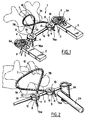
- the connecting device 1 designated as a whole in Figure 1, aims to immobilize two or several vertebral segments (not shown).
- Said plates generally have lights 5 to allow their adjustment in the desired position.
- the device also comprises, in a known manner a union bar 6 connecting transversely to each other the plates 2, the ends 6a of said union bar 6 cooperating with the fixing means 4 of the plates 2.
- FIG. 2 differs basically from the previous one in that plate 2 is replaced by a rigid cylindrical rod 2A and in that this cooperates not with a pedicle screw 3, but with a hook 3A.
- the union bar 6 has two fixing elements 8 and 9 intended for its connection with the free ends 7Aa and 7Ba of two ligament half-arms 7A or 7B constituting a ligament flexible 7 having previously freely surrounded a non-arthrodesic overlying spinous process 10 so that each ligament half-arm 7A, 7B has a restoring effect towards the midline of the vertebrae, ensuring self-control of their alignment during tensioning.
- the flexible ligament 7 surrounds the apophysis thorny 10 of a non-arthrodesic vertebra forming a open loop, before being connected by its ends free 7Aa, 7Ba to the two fixing elements 8 and 9 arranged on the ligament union bar (B.U.L.) 6.
- the flexible ligament 7 could also surround the spinous process 10 with a non-vertebra arthrodesic, its two half-arms 7A, 7B forming it, crossing before being connected by its free ends 7Aa, 7Ba to the two fixing elements 8 and 9 arranged on the link bar 6.
- the elements fixing 8 and 9 of the ends 7Aa, 7Ba of the ligament flexible 7 made on the union bar 6 are symmetrical relative to the ends thereof.
- bindings 8 and 9 could be placed on the union bar 6 of asymmetrically.
- the fastening elements 8 and 9 ends 7Aa, 7Ba of the flexible ligament 7 are produced in one piece with the union bar 6, or slidingly reported on said union bar 6.
- each of the fastening elements 8 and 9 of the ends 7Aa, 7Ba of the flexible ligament 7 is constituted by a cleat which is crossed right through by the bar union 6 by a hole 12 thereof and which is crossed also through a through hole 11 of said ends of the ligament 7 into which a threaded hole 14 opens, perpendicular to its longitudinal axis, which is intended for receiving an immobilizing screw 13 from the ends 7Aa. 7Ba of ligament 7, after it has surrounded a spinous process 10 of a non-arthrodesic vertebra.
- the immobilization screw 14 of the ends 7Aa, 7Ba of the ligament 7 simultaneously blocks tabs 8 and 9 on the union bar (B.U.L.) 6.
- a strand of ligament 7 is passed through hole 11 in one of the lugs 8 and fixed by tightening of screw 13 which, thanks to the wide surface of contact it has with the ligament, does not risk to tear it apart.
- This screw 13 can present, at its ligamentous end, a rounded surface integrated in the body of the screw 13 which does not rotate during the screwing, but only blocks the ligament 7.
- the ligament 7 is looped or crossed around the thorny overlying 10 (two or more), crossed under the edge inferior of the overlying thorny and finally passed into the hole 11 of the other cleat 9.
- the ligament 7 is therefore placed in tension using a suitable clamp and fixed by tightening the second screw 13.
- the cleats 8 and 9 can be in one piece with respect to the connecting bar 6 or symmetrically attached or asymmetrically with respect to its ends.
- the latter in order to avoid deterioration of the ligament part located to the right of the screw 13 in the cleat 8 when tightening said screw 13, the latter is provided at its end with a intermediate contact element, mounted to rotate freely on said end, so as to avoid any friction on the ligament.
Abstract
Description
La présente invention concerne un dispositif de liaison intervertébrale du type constitué, d'une part, par des plaques ou tiges rigides disposées longitudinalement de part et d'autre desdites vertèbres par l'intermédiaire de vis pédiculaires ou crochets et de moyens de fixation les surmontant, lesdites plaques ou tiges étant reliées transversalement entre elles par une barre d'union dont les extrémités coopèrent avec lesdits moyens de fixation pour assurer une arthrodèse et, d'autre part, par au moins un ligament textile artificiel souple reliant ladite barre d'union à une vertèbre libre non arthrodésée située à une certaine distance de ladite barre d'union.The present invention relates to a device for intervertebral connection of the type constituted, on the one hand, by rigid plates or rods arranged longitudinally on either side of said vertebrae via pedicle screws or hooks and fixing means overcoming them, said plates or rods being connected transversely between them by a bar of union of which the ends cooperate with said fixing means to ensure arthrodesis and, on the other hand, by at least a flexible artificial textile ligament connecting said bar union with a non-arthrodesic free vertebra located at a certain distance from said union bar.
Un tel dispositif a pour rôle, en associant une barre d'union rigide et une liaison ligamentaire interépineuse, de réaliser une ligamentoplastie intervertébrale de la zone de jonction rachidienne entre une partie rigide arthrodésée et une partie libre.The role of such a device is to combine a bar rigid union and interspinous ligament connection, to perform an intervertebral ligamentoplasty of the spinal junction zone between a rigid part arthrodesis and a free part.
Un tel dispositif a pour objectif de :
- faciliter l'ostéo-intégration de la greffe osseuse grâce aux micro-mouvements résiduels,
- prévenir une rupture brutale des contraintes au niveau des segments adjacents, à l'origine de déstabilisation iatrogène ascendante.
- facilitate osteointegration of the bone graft thanks to residual micro-movements,
- to prevent a sudden rupture of the stresses at the level of the adjacent segments, at the origin of ascending iatrogenic destabilization.
En effet, si les résultats immédiats de la chirurgie lombaire sont satisfaisants dans les 70 à 85 % des cas selon les différentes techniques, les résultats secondaires sont souvent moins bons, à cause de l'apparition au-dessus de l'arthrodèse d'une instabilité ou d'une sténose (jusqu'à 40 % selon les différentes séries). L'origine de ces problèmes est sûrement la rupture dans l'absorption des contraintes.Indeed if the immediate results of the surgery lumbar are satisfactory in 70 to 85% of cases according to the different techniques, the results are often worse because of the appearance above the arthrodesis of instability or a stenosis (up to 40% depending on the different series). The origin of these problems is surely the rupture in the absorption of stresses.
Pour obtenir ces résultats, il est connu un système semi-rigide ligamentaire, associant une ostéosynthèse rigide et une ligamentoplastie interépineuse à la zone de jonction, afin d'obtenir un certain degré d'élasticité contrôlée, en bout de fixation. Le but est d'éviter le phénomène de la néo-charnière, sus-jacent l'arthrodèse, responsable de l'arthrose des articulations interapophysaires et de la dégénérescence discale, facteurs de mauvais résultats secondaires.To obtain these results, a system is known. semi-rigid ligament, associating an osteosynthesis rigid and interspinous ligamentoplasty at the area of junction, in order to obtain a certain degree of elasticity controlled, at the end of the fixing. The goal is to avoid the phenomenon of the neo-hinge, overlying the arthrodesis, responsible for osteoarthritis of the joints interapophyseal and disc degeneration, factors for poor secondary outcomes.
La ligamentoplastie est un système semi-contraint connu qui évite les contacts interfacettaires et interépineux appuyés, tandis que l'axe de rotation vertébral est stabilisé en arrière de l'espace postérieur interdiscal. La remise en lordose permet une précontrainte postérieure permettant le verrouillage lombaire automatique.Ligamentoplasty is a semi-constrained system known which avoids interfacettary contacts and interspinous supported, while the axis of rotation vertebral is stabilized behind the posterior space interdiscal. Reordering allows for prestressing posterior allowing lumbar locking automatic.
Parmi les techniques utilisées à ce jour, les plus fréquentes sont les ligamentoplasties interpédiculaires avec fixation sur les têtes des vis vertébrales et les ligamentoplasties interépineuses avec l'utilisation de cale métallique ou en polyéthylène, de coussinet interépineux, de prothèse intervertébrale en titane, d'anneau interépineux en Dacron ou cage autobloquante.Among the techniques used to date, the most frequent are the interpedicular ligamentoplasties with fixation on the heads of the vertebral screws and interspinous ligamentoplasty with the use of metallic or polyethylene shim, bearing interspinous, of intervertebral prosthesis in titanium, interspinous ring in Dacron or self-locking cage.
Les ligamentoplasties interpédiculaires sont critiquables car il s'agit d'une technique agressive et iatrogène. En effet, l'utilisation de vis pédiculaires qui ont en général un gros diamètre, est en elle-même un geste iatrogène à cause du risque radiculaire lié à la visée pédiculaire et rend difficile une éventuelle reprise chirurgicale. Le site d'implantation des vis contraint à sacrifier partiellement les massifs articulaires susjacents (d'une vertèbre a priori saine) et entame la cohésion facettaire capsulo-ligamentaire, avec le résultat d'un facet-syndrome douloureux. Par ailleurs, les ligaments étant au contact des zones interarticulaires, ils ont tendance à travailler en hyperappui, ce qui aggrave l'hyperpression des facettes. Le relâchement capsulo-ligamentaire, associé à une dégénérescence discale, est à l'origine d'épisodes lombalgiques aigus qui témoignent d'une instabilité lombaire évolutive.Interpedicular ligamentoplasties are criticizable because it is an aggressive technique and iatrogenic. Indeed, the use of pedicle screws which usually have a large diameter, is in itself a gesture iatrogenic because of the root risk linked to aiming pedicle and makes difficult a possible recovery surgical. The screw installation site requires partially sacrifice the overlying joint mass (of a healthy vertebra) and begins the capsuloligamentary facet cohesion, with the result of a painful facet-syndrome. In addition, ligaments being in contact with the interarticular zones, they tend to work in hyper support, which aggravates the hyperpressure of the facets. The relaxation capsulo-ligament, associated with degeneration disc, is responsible for acute low back pain episodes which testify to progressive lumbar instability.
Enfin, les ligamentoplasties interpédiculaires déplacent en avant et latéralement l'action de la ligamentoplastie et diminuent la mobilité du segment concerné seulement en flexion frontale, en contrôlant de façon très limitée l'extension et surtout les translations latérales. En revanche, elles ne coupent pas les ponts pour une chirurgie d'arthrodèse et, d'autre part, il est possible de réaliser un système semi-rigide par une fixation mixte barre d'union vertébrale et ligament, dite « B.U.L. », toujours avec vis pédiculaires, de chaque côté des lames vertébrales. Un dispositif de ce type est décrit dans la demande de brevet français N° 2.749.155.Finally, the interpedicular ligamentoplasties move the action of the ligamentoplasty and decrease segment mobility concerned only in frontal flexion, controlling very limited extension and especially translations side. However, they do not cut ties for arthrodesis surgery and on the other hand it is possible to realize a semi-rigid system by a mixed fixation of the vertebral union bar and ligament, called "B.U.L. ", Always with pedicle screws, on each side vertebral blades. A device of this type is described in French patent application No. 2,749,155.
Les ligamentoplasties interépineuses également connues sont plus efficaces du point de vue biomécanique car elles permettent d'obtenir un meilleur moment stabilisateur. En effet, le centre permanent de rotation des vertèbres étant situé dans le tiers postérieur du disque, les apophyses épineuses sont anatomiquement beaucoup plus éloignées du tiers postérieur du disque que la partie postérieure des pédicules. Placées à distance des centres de rotation, elles sont actives par le bras de levier des apophyses épineuses (action du ligament artificiel). Par conséquent, la ligamentoplastie interépineuse du segment libre sus-jacent l'arthrodèse permet de limiter la mobilité (15-20 %), sans la supprimer, en contrôlant les mouvements en flexion-extension et en inclinaison latérale et les translations sagittales par une mise en tension contrôlée. La mise en place possible, mais pas nécessaire, d'un coussinet interépineux qui agit comme un amortisseur, évite le contact interépineux en extension et, par effet délordosant, la surcharge en compression des articulations postérieures, tout en réouvrant les foramens. The interspinous ligamentoplasties also known are more efficient from a biomechanical point of view because they provide a better time stabilizer. Indeed, the permanent center of rotation vertebrae being located in the posterior third of the disc, the spinous processes are anatomically much further from the posterior third of the disc than the posterior part of the pedicles. Placed at a distance centers of rotation, they are activated by the arm of lever of the spinous processes (action of the ligament artificial). Therefore, ligamentoplasty interspinous free segment overlying the arthrodesis helps limit mobility (15-20%), without remove, controlling flexion-extension movements and in lateral tilt and translations sagittal by controlled tensioning. Setting possible, but not necessary, place of a pad interspinous which acts as a shock absorber, avoids the interspinous contact in extension and, by effect delordosing, compression overload of the joints posterior, while reopening the foramens.
Avec les dispositifs actuels, les ligamentoplasties interépineuses, sans ancrage pédiculaire, posent aussi des problèmes de fiabilité technique car la force de mise en tension est relativement modérée et difficile à contrôler et la fixation du ligament à lui-même est très aléatoire et mécaniquement peu résistante.With current devices, ligamentoplasties interspinous, without pedicle anchoring, also pose technical reliability issues because the setting force tension is relatively moderate and difficult to control and the attachment of the ligament to itself is very random and mechanically weak.
La présente invention a pour but de remédier à l'ensemble de ces inconvénients et concerne à cet effet un dispositif de liaison intervertébrale du type constitué, d'une part, par des plaques ou tiges rigides disposées longitudinalement de part et d'autre desdites vertèbres par l'intermédiaire de vis pédiculaires ou crochets et des moyens de fixation les surmontant, lesdites plaques ou tiges étant reliées transversalement entre elles par une barre d'union dont les extrémités coopèrent avec lesdits moyens de fixation pour assurer une arthrodèse et, d'autre part, par au moins un ligament textile artificiel souple reliant ladite barre à une vertèbre libre non arthrodésée située à une certaine distance de ladite barre d'union ligamentaire B.U.L., caractérisé en ce que la barre d'union (B.U.L.) comporte deux éléments de fixation destinés à sa liaison avec les extrémités libres de deux demi-bras ligamentaires constituant un ligament souple ayant préalablement entouré librement une apophyse épineuse sus-jacente non arthrodésée, de manière à ce que chaque demi-bras ligamentaire exerce un effet de rappel vers la ligne médiane des vertèbres, assurant l'autocontrôle de leur alignement lors d'une mise en tension.The object of the present invention is to remedy all of these drawbacks and to this end concerns a constituted intervertebral connection device, on the one hand, by rigid plates or rods arranged longitudinally on either side of said vertebrae by means of pedicle screws or hooks and fixing means surmounting them, said plates or rods being connected transversely to each other by a union bar whose ends cooperate with said fastening means to ensure arthrodesis and, on the other hand, by at least one flexible artificial textile ligament connecting the said bar to a non-arthrodesic free vertebra located at a certain distance from said union bar ligament B.U.L., characterized in that the bar union (B.U.L.) has two fixing elements intended for its connection with the free ends of two ligament half-arms constituting a flexible ligament having previously freely surrounded an apophysis non-arthrodesic overlying thorn, so that each ligament half-arm exerts a booster effect towards the midline of the vertebrae, ensuring the self-checking of their alignment during an implementation voltage.
Ainsi et contrairement aux dispositifs connus précités ci-dessus, la mise en tension du ligament interépineux, fiablement fixé de chaque côté sur la barre d'union transversale ligamentaire (B.U.L.), favorise la transmission progressive des contraintes entre le segment rigide et le segment mobile. So, unlike known devices above, tensioning the ligament interspinous, reliably fixed on each side on the bar transverse ligament union (B.U.L.), promotes progressive transmission of stresses between the segment rigid and mobile segment.
De cette façon, une mise en tension contrôlée peut être assurée et cela est le meilleur garant de l'efficience des principes biomécaniques.In this way, a controlled tensioning can be assured and this is the best guarantor of the efficiency of biomechanical principles.
En fait, la différence fondamentale de l'invention par rapport aux dispositifs de l'art antérieur réside dans le fait que la mise en oeuvre du ligament souple ne nécessite pas la mise en place de vis pédiculaires d'aucune sorte.In fact, the fundamental difference of the invention compared to the devices of the prior art resides in the fact that the use of the flexible ligament does not no need to install pedicle screws of any kind.
Ainsi, l'invention s'adapte sur toutes les instrumentations d'arthrodèse vertébrale, et permet de remédier aux divers inconvénients des ligamentoplasties interépineuses et interpédiculaires, ne disposant pas de dispositif objet de l'invention. Ce dernier permet de pouvoir utiliser la fixation ligamentaire de façon systématique, avec un geste chirurgical simple en fin d'intervention, nécessitant seulement 5 à 10 mn pour sa mise en place.Thus, the invention can be adapted to all vertebral arthrodesis instrumentation, and allows remedy the various disadvantages of ligamentoplasty interspinous and interpedicular, not having device object of the invention. The latter allows ability to use ligament fixation systematic, with a simple surgical gesture at the end intervention, requiring only 5 to 10 minutes for its implementation.
La présente invention concerne également les caractéristiques qui ressortiront au cours de la description qui va suivre et qui devront être considérées isolément ou selon toutes leurs combinaisons techniques possibles.The present invention also relates to characteristics that will emerge during the description which will follow and which should be considered individually or in all their technical combinations possible.
Cette description, donnée à titre d'exemple non limitatif, fera mieux comprendre comment l'invention peut être réalisée, en référence aux dessins annexés sur lesquels :
- la figure 1 représente en perspective un dispositif de liaison intervertébrale selon l'invention mettant en oeuvre des plaques fixées sur des têtes de vis pédiculaires ;
- la figure 2 représente en perspective un dispositif de liaison intervertébrale selon l'invention mettant en oeuvre des tiges cylindriques associées à des crochets.
- Figure 1 shows in perspective an intervertebral connecting device according to the invention using plates fixed on the heads of pedicle screws;
- Figure 2 shows in perspective an intervertebral connecting device according to the invention using cylindrical rods associated with hooks.
Le dispositif de liaison 1 désigné dans son ensemble sur la figure 1, a pour but d'immobiliser deux ou plusieurs segments vertébraux (non représentés).The connecting device 1 designated as a whole in Figure 1, aims to immobilize two or several vertebral segments (not shown).
Il est constitué de manière connue par des plaques 2
disposées longitudinalement de part et d'autre desdites
vertèbres pour assurer une arthrodèse.It is constituted in a known manner by
Ceci est effectué par l'intermédiaire de vis
pédiculaires 3 et de moyens de fixation 4 surmontant
lesdites vis 3, et qui sont généralement constitués par
une extrémité filetée de celles-ci et d'un écrou adapté.This is done via
Lesdites plaques disposent généralement de lumières 5
pour permettre leur réglage en position souhaitée.Said plates generally have
Le dispositif comprend également de manière connue
une barre d'union 6 reliant transversalement entre elles
les plaques 2, les extrémités 6a de ladite barre d'union 6
coopérant avec les moyens de fixation 4 des plaques 2.The device also comprises, in a known manner
a
L'exemple de réalisation selon la figure 2 diffère
essentiellement du précédent en ce que la plaque 2 est
remplacée par une tige cylindrique rigide 2A et en ce que
celle-ci coopère non pas avec une vis pédiculaire 3, mais
avec un crochet 3A.The example of embodiment according to FIG. 2 differs
basically from the previous one in that
Selon l'invention se rapportant tant à l'exemple de
la figure 1 qu'à celui de la figure 2, la barre d'union 6
comporte deux éléments de fixation 8 et 9 destinés à sa
liaison avec les extrémités libres 7Aa et 7Ba de deux
demi-bras ligamentaires 7A ou 7B constituant un ligament
souple 7 ayant préalablement entouré librement une
apophyse épineuse 10 sus-jacente non arthrodésée, de
manière à ce que chaque demi-bras ligamentaire 7A, 7B
exerce un effet de rappel vers la ligne médiane des
vertèbres, assurant l'autocontrôle de leur alignement lors
d'une mise en tension.According to the invention relating both to the example of
Figure 1 than in Figure 2, the
Selon les présents exemples de réalisation des
figures 1 et 2, le ligament souple 7 entoure l'apophyse
épineuse 10 d'une vertèbre non arthrodésée en formant une
boucle ouverte, avant d'être reliée par ses extrémités
libres 7Aa, 7Ba aux deux éléments de fixation 8 et 9
disposés sur la barre d'union ligamentaire (B.U.L.) 6.According to the present exemplary embodiments of the
Figures 1 and 2, the
Bien entendu, le ligament souple 7 pourrait également
entourer l'apophyse épineuse 10 d'une vertèbre non
arthrodésée, ses deux demi-bras 7A, 7B le formant, se
croisant avant d'être reliés par ses extrémités libres
7Aa, 7Ba aux deux éléments de fixation 8 et 9 disposés sur
la barre d'union 6.Of course, the
Selon les présents modes de réalisation, les éléments
de fixation 8 et 9 des extrémités 7Aa, 7Ba du ligament
souple 7 réalisés sur la barre d'union 6 sont symétriques
par rapport aux extrémités de celle-ci.According to the present embodiments, the elements
fixing 8 and 9 of the ends 7Aa, 7Ba of the ligament
flexible 7 made on the
Mais bien entendu, les mêmes éléments des fixations 8
et 9 pourraient être disposés sur la barre d'union 6 de
façon asymétrique.But of course, the same elements of the
De la même manière, les éléments de fixation 8 et 9
des extrémités 7Aa, 7Ba du ligament souple 7 sont réalisés
de façon monobloc avec la barre d'union 6, ou encore
rapportés de manière coulissante sur ladite barre d'union
6.Similarly, the
Selon le présent exemple de réalisation, nullement
limitatif, chacun des éléments de fixation 8 et 9 des
extrémités 7Aa, 7Ba du ligament souple 7 est constitué par
un taquet qui est traversé de part en part par la barre
d'union 6 par un trou 12 de celle-ci et qui est traversé
également par un trou de passage 11 desdites extrémités du
ligament 7 dans lequel débouche un trou fileté 14,
perpendiculaire à son axe longitudinal, qui est destiné à
recevoir une vis d'immobilisation 13 des extrémités 7Aa.
7Ba du ligament 7, après que celui-ci ait entouré une
apophyse épineuse 10 d'une vertèbre non arthrodésée.According to the present embodiment, in no way
limitative, each of the
Selon une autre caractéristique de l'invention, la
vis d'immobilisation 14 des extrémités 7Aa, 7Ba du
ligament 7 bloque simultanément les taquets 8 et 9 sur la
barre d'union (B.U.L.) 6. According to another characteristic of the invention, the
immobilization screw 14 of the ends 7Aa, 7Ba of the
Après la fixation de la barre d'union 6 sur
l'instrumentation vertébrale, en général un niveau plus
bas de l'étage de la ligamentoplastie interépineuse (par
exemple niveau L5 pour ligamentoplastie L3-L4), à titre
d'exemple mais non limitatif, un brin du ligament 7 est
passé dans le trou 11 d'un des taquets 8 et fixé par
serrage de la vis 13 qui, grâce à la surface large de
contact qu'elle présente avec le ligament, ne risque pas
de déchirer ce dernier. Cette vis 13 peut présenter, à son
extrémité ligamentaire, une surface arrondie intégrée dans
le corps de la vis 13 qui ne tourne pas lors du vissage,
mais bloque seulement le ligament 7. Ensuite, le ligament
7 est passé en boucle ou en croix autour des épineuses
sus-jacentes 10 (deux ou plusieurs), croisé sous le bord
inférieur de l'épineuse sus-jacente et, enfin, passé dans
le trou 11 de l'autre taquet 9. Le ligament 7 est donc mis
en tension à l'aide d'une pince adaptée et fixé par
serrage de la deuxième vis 13.After fixing the
Dans le cas où la barre d'union transversale 6 est de
section orthogonale sous forme d'une plaque (figure 1) ou
sous forme d'une tige de section circulaire (figure 2),
les taquets 8 et 9 peuvent être monoblocs par rapport à la
barre de liaison 6 ou rapportés symétriquement ou
asymétriquement par rapport à ses extrémités.In the case where the
Dans ce système de fixation ligamentaire des
épineuses adjacentes, l'arthrodèse par une barre d'union
transversale 6 équipée de deux taquets 8, 9 est préférable
à une simple barre transversale qui serait sans taquet de
fixation ligamentaire, mais tous les moyens de fixation du
ligament interépineux 7 sur la barre transversale (B.U.L.)
6 peuvent être valables et correspondent au principe du
dispositif objet de l'invention.In this ligament fixation system
adjacent spines, arthrodesis by a bar of union
transverse 6 equipped with two
Selon une autre caractéristique de l'invention, afin
d'éviter la détérioration de la partie de ligament situé
au droit de la vis 13 dans le taquet 8 lors du serrage de
ladite vis 13, celle-ci est pourvue à son extrémité d'un
élément de contact intermédiaire, monté libre en rotation
sur ladite extrémité, de manière à éviter toute friction
sur le ligament.According to another characteristic of the invention, in order
to avoid deterioration of the ligament part located
to the right of the
Claims (7)
Applications Claiming Priority (2)
| Application Number | Priority Date | Filing Date | Title |
|---|---|---|---|
| FR9800212 | 1998-01-12 | ||
| FR9800212A FR2773463B1 (en) | 1998-01-12 | 1998-01-12 | INTERVERTEBRAL CONNECTION DEVICE |
Publications (1)
| Publication Number | Publication Date |
|---|---|
| EP0928603A1 true EP0928603A1 (en) | 1999-07-14 |
Family
ID=9521669
Family Applications (1)
| Application Number | Title | Priority Date | Filing Date |
|---|---|---|---|
| EP99400052A Withdrawn EP0928603A1 (en) | 1998-01-12 | 1999-01-11 | Intervertebral connecting device |
Country Status (2)
| Country | Link |
|---|---|
| EP (1) | EP0928603A1 (en) |
| FR (1) | FR2773463B1 (en) |
Cited By (23)
| Publication number | Priority date | Publication date | Assignee | Title |
|---|---|---|---|---|
| WO1999053855A1 (en) * | 1998-04-16 | 1999-10-28 | Dimso (Distribution Medicale Du Sud-Ouest) | Backbone osteosynthesis with frame and wires |
| FR2887434A1 (en) * | 2005-06-28 | 2006-12-29 | Jean Taylor | Surgical equipment for treatment of vertebrae, has rigid walls extending over each side of spinous process of treated vertebrae, to limit pivot movements of vertebrae about axis perpendicular to intervertebral disk |
| US8048129B2 (en) * | 2007-08-15 | 2011-11-01 | Zimmer Spine, Inc. | MIS crosslink apparatus and methods for spinal implant |
| WO2016166448A1 (en) * | 2015-04-17 | 2016-10-20 | Implanet | Vertebral fixation device |
| EP2967685A4 (en) * | 2013-03-14 | 2016-12-07 | Spinal Elements Inc | Apparatus for bone stabilization and distraction and methods of use |
| US9675387B2 (en) | 2004-02-06 | 2017-06-13 | Spinal Elements, Inc. | Vertebral facet joint prosthesis and method of fixation |
| US9743937B2 (en) | 2007-02-22 | 2017-08-29 | Spinal Elements, Inc. | Vertebral facet joint drill and method of use |
| US9808294B2 (en) | 2011-02-24 | 2017-11-07 | Spinal Elements, Inc. | Methods and apparatus for stabilizing bone |
| US9820784B2 (en) | 2013-03-14 | 2017-11-21 | Spinal Elements, Inc. | Apparatus for spinal fixation and methods of use |
| US9839450B2 (en) | 2013-09-27 | 2017-12-12 | Spinal Elements, Inc. | Device and method for reinforcement of a facet |
| USD810942S1 (en) | 2011-10-26 | 2018-02-20 | Spinal Elements, Inc. | Interbody bone implant |
| USD812754S1 (en) | 2013-03-14 | 2018-03-13 | Spinal Elements, Inc. | Flexible elongate member with a portion configured to receive a bone anchor |
| US9931142B2 (en) | 2004-06-10 | 2018-04-03 | Spinal Elements, Inc. | Implant and method for facet immobilization |
| US10022161B2 (en) | 2011-02-24 | 2018-07-17 | Spinal Elements, Inc. | Vertebral facet joint fusion implant and method for fusion |
| US10194955B2 (en) | 2013-09-27 | 2019-02-05 | Spinal Elements, Inc. | Method of placing an implant between bone portions |
| US10456174B2 (en) | 2017-07-31 | 2019-10-29 | Medos International Sarl | Connectors for use in systems and methods for reducing the risk of proximal junctional kyphosis |
| US10463403B2 (en) | 2017-07-31 | 2019-11-05 | Medos International Sarl | Systems and methods for reducing the risk of proximal junctional kyphosis using a bone anchor or other attachment point |
| US10595904B2 (en) | 2011-09-14 | 2020-03-24 | Band-Lok, Llc | Tensioning instrument and band clamp tensioning system |
| US10758361B2 (en) | 2015-01-27 | 2020-09-01 | Spinal Elements, Inc. | Facet joint implant |
| US11304733B2 (en) | 2020-02-14 | 2022-04-19 | Spinal Elements, Inc. | Bone tie methods |
| US11457959B2 (en) | 2019-05-22 | 2022-10-04 | Spinal Elements, Inc. | Bone tie and bone tie inserter |
| US11464552B2 (en) | 2019-05-22 | 2022-10-11 | Spinal Elements, Inc. | Bone tie and bone tie inserter |
| US11478275B2 (en) | 2014-09-17 | 2022-10-25 | Spinal Elements, Inc. | Flexible fastening band connector |
Citations (2)
| Publication number | Priority date | Publication date | Assignee | Title |
|---|---|---|---|---|
| GB2208476A (en) * | 1987-08-07 | 1989-04-05 | Seyed Mohammad Hossein Mehdian | Improvements in or relating to apparatus for use in the treatment of spinal disorders |
| FR2749155A1 (en) | 1996-05-29 | 1997-12-05 | Alby Albert P | Surgical vertebral connector |
-
1998
- 1998-01-12 FR FR9800212A patent/FR2773463B1/en not_active Expired - Fee Related
-
1999
- 1999-01-11 EP EP99400052A patent/EP0928603A1/en not_active Withdrawn
Patent Citations (2)
| Publication number | Priority date | Publication date | Assignee | Title |
|---|---|---|---|---|
| GB2208476A (en) * | 1987-08-07 | 1989-04-05 | Seyed Mohammad Hossein Mehdian | Improvements in or relating to apparatus for use in the treatment of spinal disorders |
| FR2749155A1 (en) | 1996-05-29 | 1997-12-05 | Alby Albert P | Surgical vertebral connector |
Cited By (47)
| Publication number | Priority date | Publication date | Assignee | Title |
|---|---|---|---|---|
| WO1999053855A1 (en) * | 1998-04-16 | 1999-10-28 | Dimso (Distribution Medicale Du Sud-Ouest) | Backbone osteosynthesis with frame and wires |
| US9675387B2 (en) | 2004-02-06 | 2017-06-13 | Spinal Elements, Inc. | Vertebral facet joint prosthesis and method of fixation |
| US10085776B2 (en) | 2004-02-06 | 2018-10-02 | Spinal Elements, Inc. | Vertebral facet joint prosthesis and method of fixation |
| US9931142B2 (en) | 2004-06-10 | 2018-04-03 | Spinal Elements, Inc. | Implant and method for facet immobilization |
| FR2887434A1 (en) * | 2005-06-28 | 2006-12-29 | Jean Taylor | Surgical equipment for treatment of vertebrae, has rigid walls extending over each side of spinous process of treated vertebrae, to limit pivot movements of vertebrae about axis perpendicular to intervertebral disk |
| WO2007000634A1 (en) * | 2005-06-28 | 2007-01-04 | Jean Taylor | Equipment for surgical treatment of two vertebrae |
| US7846186B2 (en) | 2005-06-28 | 2010-12-07 | Kyphon SÀRL | Equipment for surgical treatment of two vertebrae |
| US9743937B2 (en) | 2007-02-22 | 2017-08-29 | Spinal Elements, Inc. | Vertebral facet joint drill and method of use |
| US8608780B2 (en) | 2007-08-15 | 2013-12-17 | Zimmer Spine, Inc. | MIS crosslink apparatus and methods for spinal implant |
| US8048129B2 (en) * | 2007-08-15 | 2011-11-01 | Zimmer Spine, Inc. | MIS crosslink apparatus and methods for spinal implant |
| US10022161B2 (en) | 2011-02-24 | 2018-07-17 | Spinal Elements, Inc. | Vertebral facet joint fusion implant and method for fusion |
| US11464551B2 (en) | 2011-02-24 | 2022-10-11 | Spinal Elements, Inc. | Methods and apparatus for stabilizing bone |
| US9808294B2 (en) | 2011-02-24 | 2017-11-07 | Spinal Elements, Inc. | Methods and apparatus for stabilizing bone |
| US10368921B2 (en) | 2011-02-24 | 2019-08-06 | Spinal Elements, Inc. | Methods and apparatus for stabilizing bone |
| US10595904B2 (en) | 2011-09-14 | 2020-03-24 | Band-Lok, Llc | Tensioning instrument and band clamp tensioning system |
| USD926982S1 (en) | 2011-10-26 | 2021-08-03 | Spinal Elements, Inc. | Interbody bone implant |
| USD857900S1 (en) | 2011-10-26 | 2019-08-27 | Spinal Elements, Inc. | Interbody bone implant |
| USD979062S1 (en) | 2011-10-26 | 2023-02-21 | Spinal Elements, Inc. | Interbody bone implant |
| USD810942S1 (en) | 2011-10-26 | 2018-02-20 | Spinal Elements, Inc. | Interbody bone implant |
| USD884896S1 (en) | 2011-10-26 | 2020-05-19 | Spinal Elements, Inc. | Interbody bone implant |
| USD834194S1 (en) | 2011-10-26 | 2018-11-20 | Spinal Elements, Inc. | Interbody bone implant |
| USD958366S1 (en) | 2011-10-26 | 2022-07-19 | Spinal Elements, Inc. | Interbody bone implant |
| US10251679B2 (en) | 2013-03-14 | 2019-04-09 | Spinal Elements, Inc. | Apparatus for bone stabilization and distraction and methods of use |
| US9820784B2 (en) | 2013-03-14 | 2017-11-21 | Spinal Elements, Inc. | Apparatus for spinal fixation and methods of use |
| USD812754S1 (en) | 2013-03-14 | 2018-03-13 | Spinal Elements, Inc. | Flexible elongate member with a portion configured to receive a bone anchor |
| EP2967685A4 (en) * | 2013-03-14 | 2016-12-07 | Spinal Elements Inc | Apparatus for bone stabilization and distraction and methods of use |
| US10426524B2 (en) | 2013-03-14 | 2019-10-01 | Spinal Elements, Inc. | Apparatus for spinal fixation and methods of use |
| US11272961B2 (en) | 2013-03-14 | 2022-03-15 | Spinal Elements, Inc. | Apparatus for bone stabilization and distraction and methods of use |
| US9839450B2 (en) | 2013-09-27 | 2017-12-12 | Spinal Elements, Inc. | Device and method for reinforcement of a facet |
| US10624680B2 (en) | 2013-09-27 | 2020-04-21 | Spinal Elements, Inc. | Device and method for reinforcement of a facet |
| US10194955B2 (en) | 2013-09-27 | 2019-02-05 | Spinal Elements, Inc. | Method of placing an implant between bone portions |
| US11918258B2 (en) | 2013-09-27 | 2024-03-05 | Spinal Elements, Inc. | Device and method for reinforcement of a facet |
| US11517354B2 (en) | 2013-09-27 | 2022-12-06 | Spinal Elements, Inc. | Method of placing an implant between bone portions |
| US11478275B2 (en) | 2014-09-17 | 2022-10-25 | Spinal Elements, Inc. | Flexible fastening band connector |
| US10758361B2 (en) | 2015-01-27 | 2020-09-01 | Spinal Elements, Inc. | Facet joint implant |
| CN107530113A (en) * | 2015-04-17 | 2018-01-02 | 因普拉耐特公司 | Vertebra anchor system and part |
| FR3034978A1 (en) * | 2015-04-17 | 2016-10-21 | Implanet | SYSTEM, PART AND METHOD FOR VERTEBRAL ANCHORING. |
| AU2016250056B2 (en) * | 2015-04-17 | 2021-01-21 | Implanet | Vertebral fixation device |
| WO2016166448A1 (en) * | 2015-04-17 | 2016-10-20 | Implanet | Vertebral fixation device |
| US10420590B2 (en) | 2015-04-17 | 2019-09-24 | Implanet | Vertebral fixation device |
| US11207107B2 (en) | 2017-07-31 | 2021-12-28 | Medos International Sarl | Systems and methods for reducing the risk of proximal junctional kyphosis using a bone anchor or other attachment point |
| US11298158B2 (en) | 2017-07-31 | 2022-04-12 | Medos International Sarl | Connectors for use in systems and methods for reducing the risk of proximal junctional kyphosis |
| US10463403B2 (en) | 2017-07-31 | 2019-11-05 | Medos International Sarl | Systems and methods for reducing the risk of proximal junctional kyphosis using a bone anchor or other attachment point |
| US10456174B2 (en) | 2017-07-31 | 2019-10-29 | Medos International Sarl | Connectors for use in systems and methods for reducing the risk of proximal junctional kyphosis |
| US11464552B2 (en) | 2019-05-22 | 2022-10-11 | Spinal Elements, Inc. | Bone tie and bone tie inserter |
| US11457959B2 (en) | 2019-05-22 | 2022-10-04 | Spinal Elements, Inc. | Bone tie and bone tie inserter |
| US11304733B2 (en) | 2020-02-14 | 2022-04-19 | Spinal Elements, Inc. | Bone tie methods |
Also Published As
| Publication number | Publication date |
|---|---|
| FR2773463B1 (en) | 2000-03-31 |
| FR2773463A1 (en) | 1999-07-16 |
Similar Documents
| Publication | Publication Date | Title |
|---|---|---|
| EP0928603A1 (en) | Intervertebral connecting device | |
| EP1330987B1 (en) | Interspinous vertebral implant | |
| EP0645986B1 (en) | Spinal therapy apparatus | |
| EP1250101B1 (en) | Intervertebral linking device with connecting bar for fixing a linking rod | |
| CA2133766C (en) | Spinal osteosynthesis device | |
| EP1865863B1 (en) | Intervertebral implant for lumbrosacral joint | |
| EP0596788B1 (en) | Osteosynthesis device for spinal consolidation | |
| FR2887434A1 (en) | Surgical equipment for treatment of vertebrae, has rigid walls extending over each side of spinous process of treated vertebrae, to limit pivot movements of vertebrae about axis perpendicular to intervertebral disk | |
| EP1429672B1 (en) | Vertebral fixing device | |
| FR2831420A1 (en) | APPARATUS FOR HOLDING THE SPIN WITH A PINCH ASSEMBLY | |
| EP1138268A1 (en) | Device for the fixation of an interspinous wedge on the sacrum | |
| FR2806614A1 (en) | Intervertebral wedge fixing system comprises pedicular screws, and bar with thrust plate to support wedge | |
| FR2735351A1 (en) | IMPLANT FOR THE SURGICAL TREATMENT OF A VERTEBRAL ISTHUMIC FRACTURE | |
| FR2703239A1 (en) | Pin for interspinal prosthesis | |
| FR2861286A1 (en) | Intervertebral support for e.g. maintaining intervertebral space, has front zone between laminas to restore inter-vertebral space, and rear zone with lateral shoulders and two transversal projections to block support migration | |
| FR2559378A1 (en) | SCREW AND DEVICE FOR FASTENING, AND METHOD FOR STRENGTHENING THE SACRUM REGION | |
| WO1999042051A1 (en) | Interspinous prosthesis | |
| CA2289571A1 (en) | Implant for osteosynthesis device with hook | |
| EP1578289A1 (en) | Device comprising anterior plate for vertebral column support | |
| FR2715825A1 (en) | Self-aligning rod for spinal osteosynthesis apparatus | |
| FR2694182A1 (en) | Fastening for interpedicular vertebral prosthesis components - comprises bone-implanted shafts, with spherical heads engaged over upper portions for cooperation with prosthesis-attached rings | |
| FR2749155A1 (en) | Surgical vertebral connector | |
| WO1992013496A1 (en) | Frame for rigidifying a bone or a bone assembly | |
| FR2806615A1 (en) | Vertebral fracture reducing apparatus has fixings shaped to receive cylindrical components holding linking rods | |
| FR2913330A1 (en) | DEVICE FOR INTRAPEDICULAR CLOUD VERTEBRAL ANCHORING |
Legal Events
| Date | Code | Title | Description |
|---|---|---|---|
| PUAI | Public reference made under article 153(3) epc to a published international application that has entered the european phase |
Free format text: ORIGINAL CODE: 0009012 |
|
| AK | Designated contracting states |
Kind code of ref document: A1 Designated state(s): CH DE ES FR GB IT LI PT |
|
| AX | Request for extension of the european patent |
Free format text: AL;LT;LV;MK;RO;SI |
|
| 17P | Request for examination filed |
Effective date: 20000107 |
|
| AKX | Designation fees paid |
Free format text: CH DE ES FR GB IT LI PT |
|
| STAA | Information on the status of an ep patent application or granted ep patent |
Free format text: STATUS: THE APPLICATION IS DEEMED TO BE WITHDRAWN |
|
| 18D | Application deemed to be withdrawn |
Effective date: 20030701 |