EP0929961B1 - System for network communication of image information between imaging devices according to multiple protocols - Google Patents
System for network communication of image information between imaging devices according to multiple protocols Download PDFInfo
- Publication number
- EP0929961B1 EP0929961B1 EP97909883A EP97909883A EP0929961B1 EP 0929961 B1 EP0929961 B1 EP 0929961B1 EP 97909883 A EP97909883 A EP 97909883A EP 97909883 A EP97909883 A EP 97909883A EP 0929961 B1 EP0929961 B1 EP 0929961B1
- Authority
- EP
- European Patent Office
- Prior art keywords
- network
- output
- imaging
- component
- protocol
- Prior art date
- Legal status (The legal status is an assumption and is not a legal conclusion. Google has not performed a legal analysis and makes no representation as to the accuracy of the status listed.)
- Expired - Lifetime
Links
Images

Classifications
-
- G—PHYSICS
- G16—INFORMATION AND COMMUNICATION TECHNOLOGY [ICT] SPECIALLY ADAPTED FOR SPECIFIC APPLICATION FIELDS
- G16H—HEALTHCARE INFORMATICS, i.e. INFORMATION AND COMMUNICATION TECHNOLOGY [ICT] SPECIALLY ADAPTED FOR THE HANDLING OR PROCESSING OF MEDICAL OR HEALTHCARE DATA
- G16H30/00—ICT specially adapted for the handling or processing of medical images
- G16H30/20—ICT specially adapted for the handling or processing of medical images for handling medical images, e.g. DICOM, HL7 or PACS
-
- H—ELECTRICITY
- H04—ELECTRIC COMMUNICATION TECHNIQUE
- H04L—TRANSMISSION OF DIGITAL INFORMATION, e.g. TELEGRAPHIC COMMUNICATION
- H04L9/00—Cryptographic mechanisms or cryptographic arrangements for secret or secure communications; Network security protocols
- H04L9/40—Network security protocols
-
- G—PHYSICS
- G16—INFORMATION AND COMMUNICATION TECHNOLOGY [ICT] SPECIALLY ADAPTED FOR SPECIFIC APPLICATION FIELDS
- G16H—HEALTHCARE INFORMATICS, i.e. INFORMATION AND COMMUNICATION TECHNOLOGY [ICT] SPECIALLY ADAPTED FOR THE HANDLING OR PROCESSING OF MEDICAL OR HEALTHCARE DATA
- G16H40/00—ICT specially adapted for the management or administration of healthcare resources or facilities; ICT specially adapted for the management or operation of medical equipment or devices
- G16H40/60—ICT specially adapted for the management or administration of healthcare resources or facilities; ICT specially adapted for the management or operation of medical equipment or devices for the operation of medical equipment or devices
- G16H40/67—ICT specially adapted for the management or administration of healthcare resources or facilities; ICT specially adapted for the management or operation of medical equipment or devices for the operation of medical equipment or devices for remote operation
-
- H—ELECTRICITY
- H04—ELECTRIC COMMUNICATION TECHNIQUE
- H04L—TRANSMISSION OF DIGITAL INFORMATION, e.g. TELEGRAPHIC COMMUNICATION
- H04L65/00—Network arrangements, protocols or services for supporting real-time applications in data packet communication
- H04L65/80—Responding to QoS
-
- H—ELECTRICITY
- H04—ELECTRIC COMMUNICATION TECHNIQUE
- H04N—PICTORIAL COMMUNICATION, e.g. TELEVISION
- H04N1/00—Scanning, transmission or reproduction of documents or the like, e.g. facsimile transmission; Details thereof
- H04N1/32—Circuits or arrangements for control or supervision between transmitter and receiver or between image input and image output device, e.g. between a still-image camera and its memory or between a still-image camera and a printer device
- H04N1/32502—Circuits or arrangements for control or supervision between transmitter and receiver or between image input and image output device, e.g. between a still-image camera and its memory or between a still-image camera and a printer device in systems having a plurality of input or output devices
- H04N1/32507—Circuits or arrangements for control or supervision between transmitter and receiver or between image input and image output device, e.g. between a still-image camera and its memory or between a still-image camera and a printer device in systems having a plurality of input or output devices a plurality of input devices
- H04N1/32512—Circuits or arrangements for control or supervision between transmitter and receiver or between image input and image output device, e.g. between a still-image camera and its memory or between a still-image camera and a printer device in systems having a plurality of input or output devices a plurality of input devices of different type, e.g. internal and external devices
-
- H—ELECTRICITY
- H04—ELECTRIC COMMUNICATION TECHNIQUE
- H04N—PICTORIAL COMMUNICATION, e.g. TELEVISION
- H04N1/00—Scanning, transmission or reproduction of documents or the like, e.g. facsimile transmission; Details thereof
- H04N1/32—Circuits or arrangements for control or supervision between transmitter and receiver or between image input and image output device, e.g. between a still-image camera and its memory or between a still-image camera and a printer device
- H04N1/32502—Circuits or arrangements for control or supervision between transmitter and receiver or between image input and image output device, e.g. between a still-image camera and its memory or between a still-image camera and a printer device in systems having a plurality of input or output devices
- H04N1/32523—Circuits or arrangements for control or supervision between transmitter and receiver or between image input and image output device, e.g. between a still-image camera and its memory or between a still-image camera and a printer device in systems having a plurality of input or output devices a plurality of output devices
- H04N1/32529—Circuits or arrangements for control or supervision between transmitter and receiver or between image input and image output device, e.g. between a still-image camera and its memory or between a still-image camera and a printer device in systems having a plurality of input or output devices a plurality of output devices of different type, e.g. internal and external devices
-
- H—ELECTRICITY
- H04—ELECTRIC COMMUNICATION TECHNIQUE
- H04N—PICTORIAL COMMUNICATION, e.g. TELEVISION
- H04N1/00—Scanning, transmission or reproduction of documents or the like, e.g. facsimile transmission; Details thereof
- H04N1/32—Circuits or arrangements for control or supervision between transmitter and receiver or between image input and image output device, e.g. between a still-image camera and its memory or between a still-image camera and a printer device
- H04N1/32561—Circuits or arrangements for control or supervision between transmitter and receiver or between image input and image output device, e.g. between a still-image camera and its memory or between a still-image camera and a printer device using a programmed control device, e.g. a microprocessor
-
- H—ELECTRICITY
- H04—ELECTRIC COMMUNICATION TECHNIQUE
- H04N—PICTORIAL COMMUNICATION, e.g. TELEVISION
- H04N1/00—Scanning, transmission or reproduction of documents or the like, e.g. facsimile transmission; Details thereof
- H04N1/32—Circuits or arrangements for control or supervision between transmitter and receiver or between image input and image output device, e.g. between a still-image camera and its memory or between a still-image camera and a printer device
- H04N1/327—Initiating, continuing or ending a single-mode communication; Handshaking therefor
- H04N1/32797—Systems adapted to communicate over more than one channel, e.g. via ISDN
-
- H—ELECTRICITY
- H04—ELECTRIC COMMUNICATION TECHNIQUE
- H04L—TRANSMISSION OF DIGITAL INFORMATION, e.g. TELEGRAPHIC COMMUNICATION
- H04L65/00—Network arrangements, protocols or services for supporting real-time applications in data packet communication
- H04L65/1066—Session management
- H04L65/1101—Session protocols
-
- H—ELECTRICITY
- H04—ELECTRIC COMMUNICATION TECHNIQUE
- H04L—TRANSMISSION OF DIGITAL INFORMATION, e.g. TELEGRAPHIC COMMUNICATION
- H04L67/00—Network arrangements or protocols for supporting network services or applications
- H04L67/01—Protocols
-
- H—ELECTRICITY
- H04—ELECTRIC COMMUNICATION TECHNIQUE
- H04L—TRANSMISSION OF DIGITAL INFORMATION, e.g. TELEGRAPHIC COMMUNICATION
- H04L69/00—Network arrangements, protocols or services independent of the application payload and not provided for in the other groups of this subclass
- H04L69/18—Multiprotocol handlers, e.g. single devices capable of handling multiple protocols
Definitions
- the present invention relates to imaging systems, and, more particularly, to systems for communicating image information between an input imaging device and an output imaging device in a network environment.
- An imaging system typically includes an input imaging device that generates image information, and an output imaging device that forms a visible representation of an image based on the image information.
- the input imaging device may include a diagnostic device, such as a magnetic resonance (MR), computed tomography (CT), conventional radiography (X-ray), or ultrasound device.
- the input imaging device may include a user interface device, such as a keypad, mouse, or trackball, which is also capable of generating medical image information.
- the input imaging device may include an image archival workstation for retrieving archived image information.
- the output imaging device in a medical imaging system typically includes a digital laser imager. The laser imager exposes an imaging media in response to the image information to form the visible representation.
- the image information generated by the input imaging device includes image data containing digital image values representative of the image, and imaging requests specifying operations to be performed by the laser imager.
- Each of the digital image values corresponds to one of a plurality of pixels in the original image, and represents an optical density associated with the respective pixel.
- the laser imager converts the digital image values to generate laser drive values used to modulate the intensity of a scanning laser.
- the laser drive values are calculated to produce exposure levels, on the imaging media, necessary to reproduce the optical densities associated with the pixels in the original image when the media is developed, either by wet chemical processing or dry thermal processing.
- the laser imager may perform a number of additional operations in response to the imaging requests generated by the input imaging device. For example, the laser imager may manipulate the image data, prior to generating the laser drive values, to produce a variety of different format and/or appearance characteristics.
- the image information processed by the laser imager has a format determined by an input protocol associated with the particular input imaging device.
- Medical imaging systems typically are capable of handling image information generated according to a variety of diverse input protocols.
- An input protocol can be characterized as including a network driver protocol, which provides lower-level communications specifications as to a particular input imaging device, and a network interpreter protocol, which determines the format for interpreting image information generated by the input imaging device.
- the number of different input protocols results, to some degree, from the various types of input imaging devices presently in use, e.g., a magnetic resonance (MR), computed tomography (CT), conventional radiography (X-ray), or ultrasound device, each of which may generate image information according to a different protocol.
- MR magnetic resonance
- CT computed tomography
- X-ray conventional radiography
- ultrasound device each of which may generate image information according to a different protocol.
- the primary source of different input protocols is, however, the existence of a number of modalities, i.e., input imaging devices made by different manufacturers and having unique, manufacturer-specific input protocols.
- manufacturers such as Siemens, Toshiba, GE, and Picker presently make CT-type input imaging devices that provide similar functionality, but which generate image information according to different modality-specific input protocols.
- an output protocol can be characterized as including an output driver protocol, which determines requirements for communication with a particular output imaging device, and an output interpreter protocol, which determines the format for translating image information into a form understood by the output imaging device.
- Different output protocols primarily result from the availability of laser imaging output devices having different sets of functional capabilities. The different sets of functional capabilities present varying complexity that can lead to different output protocols. For example, Imation Enterprise Corp. ("Imation”), of Oakdale, Minnesota, presently offers laser imagers having different sets of functional capabilities referred to as the "831," ''952,” and "SuperSet” sets, each of which is associated with a set-specific output protocol.
- the input interpreter and driver pair may be specific to a "Siemens host modality, while the output interpreter and output driver pair may be specific to an Imation laser imager using the 831 protocol. If the latter pair is replaced with a pair specific to an Imation laser imager using the SuperSet protocol, the design of the components is such that the input interpreter and driver pair does not also need to be replaced.
- U. S. Patent No. 5,630,101 promotes flexibility in laser imager architecture, it discloses only a direct-connect, point-to-point architecture.
- the interface executive For every input-output pair, the interface executive must instantiate a separate input driver-input interpreter pair and output interpreter-output driver pair. That is, the interface executive must create a separate pipeline between each host modality and each laser imager.
- this can pose a problem in environments where a significant number of host modalities communicate with a plurality of different laser imagers. This is especially true in a networking environment, in which typically a number of network clients all speak the same protocol. In such a situation, it is desirable not to have redundant a input driver-input interpreter pair for each and every client. Besides the drainage in resources, this architecture also places excessive overhead on the interface executive.
- DICOM protocol sets one standard for network communication of image information.
- other network protocols exist and will continue to be created.
- protocol translation continues to be necessary in network systems.
- the need for protocol translation in network systems creates problems similar to those encountered with point-to-point systems. Specifically, flexibility and ease of adaptation for multiple protocols continue to be of concern. Accordingly, there is a need for a system capable of providing network communication of image information between imaging devices according to multiple communication protocols.
- US Patent 5,060,140 discloses a universal programmable data communication connection system which is user programmable to provide a selective data path between one or more data source and one or more data destination.
- the data connection system allows the user to "patch" signals from source to destination with simple commands.
- the disclosed system is not directed to solving the problems associated with communicating medical information between different medical imaging modalities and at least one of a plurality of different imagers and more specifically to the problem of multiple medical imaging modalities using the same network interface protocol to communicate with one of the imagers via a single communication pipeline.
- the present invention is directed to a system for communicating medical image information between different medical imaging modalities and at least one of a plurality of different imagers via a network interface.
- the system includes a network executive component, one or more output interface components and an interface executive component.
- the network executive component instantiates one or more network interface components according to a selected one of a plurality of network interface protocols.
- Each of the network interface components is configured to receive medical image information from one of the medical imaging modalities via the network interface, the medical image information being received according to the selected network interface protocol.
- Each of the network interface protocols is specifically associated with selected medical imaging modalities. First imaging requests are generated based on the received medical image information and according to the selected network interface protocol.
- Each of the one or more output interface components is configured to generate second imaging requests based on the first imaging requests generated by one of the network interface components.
- the second imaging requests are generated according to one of a plurality of different output interface protocols.
- Each of the output interface protocols is specifically associated with one of the imagers.
- the interface executive component defines one or more communication pipelines, each of the pipelines communicatively interconnecting one or more of the imaging modalities and one of the network interface components using the same network interface protocol, one of the output interface components, and one of the imagers. Thereby, multiple medical imaging modalities using the same network interface protocol can communicate with one of the imagers via a single communication pipeline.
- the present invention provides for a number of advantages in facilitating communication between the medical imaging modalities and the imagers. Because the network executive component can facilitate communication of a number medical imaging modalities, a separate pipeline is not required for each medical imaging modality, thereby conserving resources.
- the network executive components also allow the present invention to facilitate communication between medical imaging modalities and imagers on a network level as opposed to a direct-connect manner. Furthermore, the network executive components are delegated responsibility by the interface executive component as to overseeing communication from the medical imaging modalities. This frees the interface executive component from itself having to take on this responsibility.
- the present invention effects a scalable software architecture for simultaneously translating multiple medical imaging protocols within a network paradigm.
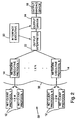
- FIG. 1 a functional block diagram of a medical imaging system 10 for communication of image information between multiple-protocol imaging devices in a network communication environment, in accordance with the present invention, is shown.
- the system 10 includes a plurality of input imaging devices in the form of network clients 12, one or more network executive components 14, one or more output interface components 16, an output imaging device 18, and an interface executive component 20.
- Each output interface component 16 includes an output interpreter component 22 and an output driver component 24.
- each of clients 12 communicates with output imaging device 18 via a particular pipeline 26 specific to a particular protocol.
- each pipeline 26 is needed to provide for communication between the clients 12 and output imaging device 18.
- each of clients 12 speaks one or two of two different protocols, then two different pipelines are needed; and so on.
- the present invention allows for N different pipelines for N different protocols, in which each pipeline is capable of handling M different clients speaking that particular protocol. That is, a separate pipeline for each client is not required, but rather only for each different protocol.
- Each pipeline 26 comprises three primary components: a network executive component 14, an output interpreter component 22 and an output driver component 24, the latter two of which are paired as a single output interface component 16.
- the system shown in FIG. 1 is set up in the following manner.
- the interface executive component 14 creates a separate pipeline 26 for each separate protocol spoken by at least one network client 12 that may communicate with imaging device 18.
- the interface executive component 14 accomplishes this by instantiating a network executive component 14 specific to the protocol spoken by one or more clients 12, and an output interface component 16 specific to output imaging device 18, a pair of particular components 14 and 16 thus making up a particular pipeline 26.
- This creation of pipelines 26 can occur either "on the fly” as clients speaking different protocols enter or leave the network of system 10, or can occur when the network is first being initialized.
- the present invention is not limited either way.
- a client 12 Upon establishment of the pipelines 26, a client 12 speaks to the output imaging device 18 in general terms in the following manner.
- Network executive component 14 filters and interprets requests received from client 12 to corresponding first requests that output interface component 16 understands.
- the first requests are further filtered and interpreted, to the particular corresponding second requests that output imaging device 18 understands.
- the present invention takes requests specific to a particular protocol, translates them into first requests, and further translates them into second requests specific to a particular imaging device.
- component 14 and component 16 can be changed independent of one another, because both speak to one another via first requests.
- a network executive component 14 specific to a particular protocol is independent of any imaging device 18, while the implementation of output interface component 16 is independent of any-given protocol spoken by a particular client 12. Note as well that this process as described is operable in reverse, such that requests from device 18 can be sent to client 12.
- the present invention thus adopts a pipeline model for allowing communication between M clients speaking N protocols to an imaging device.
- the interface executive component manages creation of these pipelines.
- a pipeline is created for each particular protocol spoken by at least one of M clients on the network. Because typically N ⁇ M, the present invention conserves resources over a system in which a separate pipeline is necessary for each client, not each protocol. This is a significant advantage of the present invention.
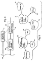
- FIG. 2 a functional block diagram of a further embodiment of the present invention is shown.
- the interface executive component may be configured to instantiate one translation pipeline with N network executive components operating independently and in parallel to one another.
- N x M clients may be supported without the inefficiency of providing N-1 output interpreter components and N-1 output driver components.
- the system 58 of FIG. 2 supports N network protocols and N x M network clients with the implementation of only one communication pipeline.
- System 58 includes a plurality of network executive components 14 that listen for network clients 12 having particular network protocols.
- the interface executive component 20 communicatively interconnects each of network executive components 14 with a single output interpreter component 22, a single output driver component 24, and a single output imaging device 18 to provide a single communication pipeline with multiple, protocol-specific network inputs.
- FIG. 2 varies from that shown in FIG. 1 in that the former embodiment conserves even more resources than does the latter.
- the embodiment shown in FIG. 1 wastes some resources by providing redundant output interface components 16 for each pipeline 26, which are all redundant due to the fact that there is only one output imaging device. This redundancy, and corresponding waste of resources, is eliminated by the embodiment shown in FIG. 2.
- FIG. 2 there is only one pipeline 26, and only one output interface component 16, to which each of network executive components 14 is coupled.
- FIG. 2 operates identically to FIG. 1, and description made in conjunction with FIG. 1 should be referred to for description of FIG. 2.
- the network executive components 14, output interface components 16, and interface executive component 20 are implemented in one embodiment as an object-oriented software system that interfaces with a network having network clients 12 and output imaging device 18.
- the software system may be implemented as part of an output imaging device 18, such as a continuous tone digital laser imager, or as part of a discrete interface device controlling communication of image information between network clients 12 and output imaging device 18.
- the network comprises a plurality of different clients, such as magnetic resonance (MR), computed tomography (CT), conventional radiography (X-ray), and ultrasound devices, manufactured by a number of different manufacturers, such as Siemens, Toshiba, GE, or Picker.
- the laser imager can be any of a number of different imagers, such as those manufactured by Imation and that understand the 831, 952, or SuperSet protocols.
- the laser imager may also reside directly on the network, in which case the software system typically resides on a hardware card inserted into the laser imager.
- the card typically comprises input/output (10) circuitry, as well as memory such as a ROM or flash ROM, which is one type of reprogrammable ROM.
- the software system resides on this memory.
- the laser imager does not reside directly on the network, and instead is coupled to the network via an intermediary computer that itself resides directly on the network.
- the intermediary computer typically has a random-access memory (RAM), a read-only memory (ROM), a central-processing unit-(CPU) and a storage device, such as a hard disk drive, programmable ROM, or disk drive.
- the software system typically resides on the storage device of the intermediary computer, and is copied into RAM and executed therefrom by the CPU.
- the storage device is a disk drive or other removable storage device
- the software system can be stored on the storage medium for insertion into the device.
- the present invention is not, however, limited to any particular hardware implementation.
- the image information generated by the input imaging devices associated with network clients 12 includes both requests for imaging operations, and image data containing digital image values representative of an image to be handled by output imaging device 18.
- pipeline 26 will be described as handling communication of image information in the form of imaging requests, with image information in the form of digital image values representative of the image being communicated by a separate communication path. It is within the scope of the invention, however, that pipeline 26 could be configured to handle communication of image information in the form of both requests for imaging operations and image data containing the digital image values.
- imaging requests include requests to initiate an image print job by output imaging device 18, requests to abort a previously initiated image print job, requests to define or modify a format of an image to be printed, requests to delete a set of image data representative of a previously acquired image, and requests to store image data in a particular image location.
- the interface executive component 20 defines one or more (1 to N) communication pipelines 26.
- Each communication pipeline 26 communicatively interconnects, or "binds," one or more of the M network clients 12, one of network executive components 14, one of output interpreter components 22, one of output driver components 24, and output imaging device 18 in a bi-directional manner.
- the output imaging device 18 may communicate with any of pipelines 26 on a shared basis. Alternatively, a plurality of output imaging devices 18 could be provided, each being communicatively interconnected with a particular pipeline 26.
- the interface executive component 20 provides for the highest level of intelligence within system 10 of FIG. 1. It governs and manages the particular network components 26 and output interface components 16 needed for clients 12 to communicate with device 18. That is, as shown in-FIG. 1, based on the N different protocols spoken by clients 12, the interface executive component 20 instantiates a particular pipeline 26 made up of a network executive component 26 and output interface component 16. Furthermore, if there are P different output imaging devices (as opposed to just one, as shown in FIG. 1), then the interface executive component instantiates N x P different pipelines, one for every unique imaging device-protocol pair. This can be accomplished in a separate set-up mode, or "on the fly" as clients speaking different protocols enter or leave the network.
- the interface executive component 20 differs from the interface executive component disclosed and described in United States patent 5,630,101 in that it has less intelligence than the interface executive component disclosed in that patent.
- the interface executive component disclosed and described in United States patent 5,630,101 instantiates an input interface component particular to every client needing to communicate with a particular imaging device. That is, the interface executive component constructs a pipeline on a client-by-client basis.
- the interface executive component of the present invention instantiates a network executive component 14 specific to a particular protocol, and thereto delegates all responsibility of serving network clients.
- the interface executive component of the present invention constructs a pipeline on a protocol-by-protocol basis.
- the interface executive component 20 defines the structure of the pipeline 26.
- the pipeline 26 is configured to communicatively interconnect a number of components 30, 32(32') (which are shown in FIG. 3 and, as shown there and as will be explained later, are instantiated by network executive component 14), 22 and 24 having different protocols on a selected basis to provide significant flexibility.
- This flexibility provides a medical imaging system 10 capable of achieving communication between a variety of different network clients 12 and one or more output imaging devices 18 having a variety of different functional capabilities.
- interface executive component 20 treats each functionally independent component 14, 22 and 24 as a "black box" with a clearly identified set of responsibilities and a defined interface.
- the interface executive component 20 selects the appropriate series of black boxes based on the environment, and binds them together with "handles" to one another to form the complete pipeline 26.
- interface executive component 20 in one embodiment is configured to dynamically bind the components "on the fly” to form a communication pipeline 26 appropriate for the current imaging environment.
- interface executive component 20 is configured to produce a scalable software architecture having a plurality of communication pipelines 26 configured according to different protocols.
- the scalable architecture enables output imaging device 18 to communicate simultaneously with several network clients 12 on a shared basis using the necessary protocols, as provided by each pipeline 26.
- a plurality of output imaging devices 18 can be provided, each being communicatively interconnected with a particular pipeline 26.
- the interface executive component 20 scales the software architecture to match the requirements of the environment, creating as many network executive components and pipelines as there are different network protocols.
- the interface executive component 20 selectively binds a series of components 14,22 and 24 having specific protocols necessary to match a particular network client 12, a particular output imaging device 18, and the required hardware interfaces.
- the network executive component 14 is responsible for handling all network clients 12 that communicate via a particular protocol. As shown in FIG. 1, a network executive component 14 is provided for each particular one ofN network protocols. Thus, network executive component 14 handles multiple network clients 12 simultaneously.
- the interface executive component 20 delegates to network executive component 14 the responsibility of managing all network-specific services.
- the interface executive component 20 instantiates a particular network executive component 14 for each medical imaging network protocol that will be supported on the network by system 10. If the Picker Networking Protocol is to be supported, for example, interface executive component 20 instantiates a network executive component 14 capable of serving such a protocol. For further example, the interface executive component 20 also instantiates another network executive component capable of serving the DICOM protocol, if that protocol is to be supported.
- the network executive component 14 governs all objects needed to manage network communication.
- the primary function of network executive component 14 is to monitor or "listen" at network interface 28 for imaging requests from network clients 12 having a particular network protocol.
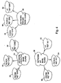
- network executive component 14 spawns a network driver component 30 and a network interpreter component 32 appropriate for that protocol, as shown in FIG. 3.
- network executive component 14 binds network driver component 30 to network interpreter component 32, and then binds network interpreter component 32 to output interpreter component 22 using handle information previously provided by the interface executive component 20.
- the network executive component 14 then returns to listening to network interface 28 for new requests sent according to the particular network protocol.
- the network driver component 30 and network interpreter component 32 together form a network interface component 33, as is also shown in FIG. 3.
- the presence of the network executive component in the present invention serves as a distinguishing characteristic of the invention over U.S. Patent No. 5,630,101.
- U.S. Patent No. 5,630,101 there is no corresponding network executive components, but rather there are input interface components.
- the input interface component is not an intelligent component as is the network executive component of the present invention. Rather, an input interface component is instantiated by the interface executive for -every -connection between a particular client and the imaging device.
- the interface executive delegates responsibility for client communication to a network executive component, which itself instantiates other components as necessary for one or more clients speaking a common protocol to communicate with the imaging device.
- the network executive components thus provide the present invention with the advantage of network communication in a resource use-minimizing manner. For example, overlaying the system disclosed in U.S. Pat. No. 5,630,101 onto a network of clients results in the creation of pipelines for each of the clients.
- an intelligent network executive component 14 the present invention eliminates the need for the creation of pipelines for each of the clients, but rather only calls for the creation of a pipeline for each of the protocols via which the clients can communicate. Because the number of communication protocols is typically far less than the number of clients, this results in a significant savings in resource use.
- the interface executive component 20 is freed from such micromanagement duties, which may otherwise overburden the interface executive component.
- network driver and network interpreter components 30 and 32 as shown in FIG. 3 are instantiated "on the fly” in response to detection by network executive component 14 of a network client 12 having a specific protocol at network interface 84, thereby conserving the hardware/software resources necessary to support such components until needed.
- This dynamic instantiation of the network driver and network interpreter components 30, 32 enables reduction in the amount of system overhead that otherwise would be necessary. If resource conservation is not a concern, such components are alternatively provided on a permanent basis to provide a fixed, dedicated pipeline 26 for each protocol.
- network executive component 14 delegates all responsibility for serving the particular network client 12 to the driverfmterpreter pair.
- the network executive component 14 communicatively binds network client 12, network driver component 30, and network interpreter component 32 to one of output interpreter components 22, using handle information previously provided to the network executive component 14 by the interface executive component 20.
- Each of network driver components 30 is configured to receive the image information from a network client 12 according to one of a plurality of different network interface protocols.
- Each network interface protocol is specifically associated with one of network clients 12, and reflects the modality-specific requirements for communication with the particular network client.
- Each of the network interpreter components 30 is configured to generate first imaging requests according to one of the network interface protocols based on the content of the received image information. The first imaging requests are generated by network interpreter component 32, and correspond to imaging requests generated by network client 12. The first imaging requests are communicated to output interface component 16.
- Each of the network interface protocols includes both a network driver protocol applicable to network driver components 30 and a network interpreter protocol applicable to network interpreter components 32.
- the appropriate network driver protocol is determined by the communication requirements of a particular network client 12, whereas the appropriate network interpreter protocol is determined by the image information format of the particular input imaging device associated with the network client.
- the image information format refers to the types of imaging requests generated according to the protocol of a particular input imaging device.
- the network driver protocol specifies the manner in which a network driver component 30 should carry out the transfer of image information from an input imaging device associated with a network client 12.
- the network interpreter protocol specifies the manner in which network interpreter component 32 should interpret the image information to generate the first imaging requests.
- the network driver and network interpreter protocols can vary significantly according to differences in the type of network client 12, as well as the manufacturer of the input imaging device 18.
- the network interpreter component 32 also shares a common set of tasks with other network interpreter components, without regard to a specific network interpreter protocol. Primarily, after obtaining image information from a network driver component 30, a network interpreter component 32 analyzes requests contained in the image information and translates them to generate first imaging requests corresponding to operations provided by output imaging device 18. The first imaging requests include requests for a variety of common imaging services provided by output imaging device 18.
- network interpreter component 32 interprets the requests generated by network client 12 may vary according to the specific network interpreter protocol.
- the network interpreter component 32 understands the precise format, instructions, and timing constraints inherent in the image information generated by a particular network client 12. Nevertheless, all network interpreter components 22 still provide a common, basic function of generating first imaging requests.
- the network interpreter component 32 sends the first imaging requests along pipeline 26. Once the first imaging requests have been processed by downstream components in bi-directional pipeline 26, and a response has been received, network interpreter component 32 forms an appropriate response for network client 12.
- the network interpreter component 32 sends the response along pipeline 26 to network client 12, via network driver component 30, which handles communication requirements necessary to transmit the response to the input imaging device.
- the network driver component 30 and network interpreter component 32 have been described in recognition that a network interface component 33 could alternatively be implemented as a single, integral software module. In the embodiment described, however, a network interface component 33 is realized by a discrete network driver component 30 and a discrete network interpreter component 32. A discrete implementation of the sub-components divides the functionality of each network interface component 33 into smaller packages for better modularity. Thus, as an example, with added modularity, changes in hardware specifications for network interface 28 require only reconfiguration of network driver component 30, instead of the entire network interface component 33.
- components 30 and 32 oflike type are configured to perform several common tasks.
- network driver components 30 share a set of common tasks necessary to communicate with a network client 12 operating according to particular network protocol.
- a network driver component 30 is configured to handle any hardware specifics such as interrupts, buffers and handshaking necessary to transfer imaging information to and from a particular network client 12.
- the network driver component 30 is further configured to handle any other specific needs of a network client 12, such as packetizing or initialization.
- the network driver component 30 performs all necessary communications tasks, isolating the remainder of pipeline 26 from any knowledge of the specific requirements for communication with the network client 12.
- the responsibility of network driver component 30 is two-fold.
- network driver component 30 receives image information off the network from network client 12, and prepares the image information for the next stage of pipeline 26, i.e., network interpreter component 32. Second, network driver component 30 transmits any responses emerging from bi-directional pipeline 26 onto the network for communication to network client 12.
- each of output interface components 16 is configured to generate second imaging requests according to one of a plurality of different output protocols, via one of output interpreter components 22, based on the content of the first imaging request.
- the second imaging requests represent the content of the first imaging requests, as translated by output interpreter component 22 for communication to output imaging device 18.
- Each output interface protocol is specifically associated with the type of output imaging device 18 and, like the network interface protocol, reflects the requirements for communication with the particular output imaging device.
- each of the output interface components 16 is configured to communicate the second imaging requests to output imaging device 18, via output driver component 24, according to one of the output interface protocols.
- Each of the output interface protocols includes an output interpreter protocol applicable to output interpreter components 22 and an output driver protocol applicable to output driver components 24.
- the output driver protocol is determined by the communication requirements of output imaging device 18, whereas the appropriate output interpreter protocol is determined by the image information format of the output imaging device.
- the output interpreter protocol specifies the manner in which output interpreter component 22 should interpret first imaging requests to generate second imaging requests in a form understood by output imaging device 18.
- the output driver protocol specifies the manner in which an output driver component 24 should carry out the transfer of second imaging requests to output imaging device 18.
- the output interface protocols are subject to variation. For example, both the output driver and output interpreter protocol can vary according to the type of functional capabilities provided by output imaging device 18, e.g., 831, 952, or SuperSet in the case of a laser imager manufactured by Imation.
- An output interpreter component 22 is configured to receive, via pipeline 26, first imaging requests generated by a network interpreter component 32, and to interpret the first imaging requests to generate second imaging requests, which conform to the particular protocol required by output imaging device 18.
- the second imaging requests correspond to the first imaging requests in substance, but are configured according to the output protocol understood by output imaging device 18. Thus, the second imaging requests serve as requests for the same imaging services specified by first imaging requests.
- the manner in which an output interpreter component 22 interprets the instructions may vary according to the specific output interpreter protocol dictated by output imaging device 18, but all output interpreter components 22 share a common task of generating second imaging requests in a protocol understood by the output imaging device.
- the output interpreter component 22 sends the second imaging requests along pipeline 26. When output imaging device 18 processes the second imaging requests and formulates a response received via pipeline 26, output interpreter component 22 removes any output protocol-specific information and forms an appropriate response for network interpreter component 32.
- an output driver component 24 is configured to handle any hardware specifics such as interrupts, buffers, and handshaking necessary to transfer imaging information to and from a particular output imaging device 18.
- the output driver component 24 isolates the remainder of pipeline 26 from any knowledge that communication with output imaging device 18 is carried out via a serial interface, a parallel interface, or a dual-port RAM, etc.
- the output driver component 24 transmits second imaging requests generated by an output interpreter component 22 to output imaging device 18, maintaining any communication requirements. Further, output driver component 24 receives responses from output imaging device 18, and prepares the response for transmission to output interpreter component 22 via bi-directional pipeline 26.
- an output interface component 16 could alternatively be implemented as a single, integral software module.
- an output interface component 16 is realized by a discrete output interpreter component 22 and a discrete output driver component 24.
- a discrete implementation of the sub-components divides the functionality of each interface component 16 into smaller packages for better modularity.
- changes in hardware specifications for interface component 16 require only reconfiguration of output driver component 24, instead of the entire interface component 16.
- the software interfaces between components 30, 32, 22 and 24 must be pre-defined to make each type of component generic.
- an individual component 30, 32, 22 and 24 must be configured to implement functions specific to a particular protocol.
- Object-oriented techniques, particularly that of inheritance, are used by the present invention to develop a generic base-class protocol for each type of component (e.g., network driver component 30).
- Inheritance is a particular object-oriented technique that serves as a mechanism for creating new classes from an existing class.
- a new class looks similar to an existing class except that it differs from the existing class in a small way; inheritance is employed to define the new class in terms of the existing class.
- the existing class that serves as a source for inheritance is referred to as a base class, and the new class derived from the base class is referred to as the derived class.
- An existing class can serve as a base class to more than one derived class.
- the base class is a definition of a more generic class of software objects, while the classes derived from the base class define more specific or specialized cases of the objects.
- the generic base-class protocol specifies the functions provided by a component and the procedures for accessing such functions. Each specific protocol component "inherits" from the corresponding base class protocol, and implements the interface to conform to the environment.
- Class inheritance allows the members of one class to be used as if they were members of a second class. No additional programming is required to implement the subclass, except for those operations that either extend or replace the members inherited from the other classes.
- subclasses are constructed out of existing classes until the appropriate functionality is developed. The construction of subclasses results in the formation of a class hierarchy The class hierarchy is rooted in the base class, which contains a minimal set of behavior common to all subclasses.
- each component 30, 32, 22 and 24 is configured according to a specific protocol, but also serves as a sub-class of the base class protocol. Because each component 30, 32, 22 and 24 inherits from the base-class protocol and implements a minimal set of functions such that they meet base-class requirements, it can be directly interchanged with any other component of like type that inherits from the same base-class protocol.
- the interchangeability resulting from the object-oriented techniques produces a "direct-connect" software architecture in which each component can be effectively plugged into pipeline 26 without the need for additional interface development.
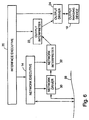
- FIGS. 5 and 6 provide an example of an object-oriented protocol hierarchy that facilitates interchangeability of components 30, 32, 22 and 24.
- the protocol hierarchy illustrates the implementation of components 30, 32, 22 and 24 for specific protocols that as a derived class each "inherit" from a generic base-class protocol.
- a network executive base-class protocol 34 may encompass a plurality of "inheriting" network executive protocols 40, 42, 44 for different network clients 12 such as, for example, DICOM, Picker, and LP that allow an appropriately-instantiated network executive component 14 to detect the presence of a particular network client.
- a network driver base protocol 36 may encompass a plurality of "inheriting" network driver protocols 46, 48, 50 for different network interface requirements associated with a network client 12 such as, for example, DICOM, Picker, or LP.
- a base-class network interpreter protocol 38 may encompass a plurality of inheriting network interpreter protocols 52, 54, 56 for different types of input imaging devices or manufacturers associated with network clients 12 such as, for example, DICOM, Picker, and LP.
- a base-class output interpreter protocol 35 may encompass a plurality of inheriting output interpreter protocols for different types of output imaging devices 18, such as an Imation SuperSet output interpreter protocol 41, an Imation 831 output interpreter protocol 43, or an Imation 952 output interpreter protocol 45.
- a base-class output driver protocol 37 may encompass a plurality of inheriting output driver protocols for different hardware interface requirements associated with output imaging device 18, such as a dual-port RAM output driver protocol 47, a serial output driver protocol 49, or a parallel output driver protocol 51.
- Each of the inheriting protocols described above includes protocol-specific functions provided by a component 30, 32, 22 and 24, but implements such functions via a generic interface that inherits from the corresponding base-class protocol 34, 35, 36, 37, 38.
- components 30, 32,22 and 24 enable them to be selectively "swapped" in or out of a pipeline 26 in a modular fashion by interface executive component 20.
- Each of the components 39, 32, 22, 24 is made interchangeable with another component of like type, but different protocol, by a series of software interfaces.
- This base-class interface is in one embodiment built into each component such that any component 30, 32, 22 and 24 in a pipeline 26 can be replaced without affecting the configuration of the other components in the pipeline.
- individual components 30, 32, 22 and 24 also can be reused, significantly reducing costs previously associated with redesign efforts.
- interface executive component 20 would first instantiate a network executive component 14 configured to monitor the presence of Siemens network clients. Upon detection of a Siemens network client 12, network executive component 14 would spawn a network driver component 30 and network interpreter component 32 configured to operate according to the Siemens network protocol. Specifically, network driver component 30 would be configured to operate according to a network driver protocol appropriate for receiving imaging information from the Siemens network client 12. The network interpreter component 32 would operate according to a network interpreter protocol appropriate for generation of first imaging requests based on the format of the image information received from the Siemens network client.
- the network executive component 14 then would communicatively bind the network driver component 30 and network interpreter component 32 with an output interpreter component 22 having an output interpreter protocol appropriate for generation of second imaging requests understood by the Imation SuperSet output imaging device, the network interpreter component 32 already being bound to an output driver component 24 having an output driver protocol appropriate for communication of the second imaging requests via a serial hardware interface associated with the Imation SuperSet output imaging device.
- a pipeline 26 were to be configured for communication between a Toshiba network client 12 and an Imation SuperSet output imaging device 18, it would only be necessary to "swap" the network driver component 30 and network interpreter component 32 with components configured according to network driver and network interpreter protocols, respectively, appropriate for the Toshiba modality.
- a network executive component 14 instantiated to listen for Toshiba network clients 12 would spawn a network driver component 30 and network interpreter component 32 configured to operate according to the Toshiba protocol.
- the output interface component 16 used for Siemens network clients 12 could be replicated and used in a separate communication pipeline 26 for Toshiba network clients.
- the output interface component 16 would include an Imation SuperSet-configured output interpreter component 22 and an Imation SuperSet serial-configured output driver component 24, and therefore would already be configured according to the requirements of output imaging device 18, independently of the protocol of network client 12.
- network executive component 14 would communicatively bind in a separate pipeline 26 the network driver and network interpreter components 30 and 32 with the standard output interpreter and output driver components 22 and 24 configured for the Imation SuperSet output imaging device, and useful in any pipeline having a Super-set output device, and which are already bound to one another.
- network executive component 14 would communicatively bind the network driver component 30 and network interpreter component 32 with an output interpreter component 22 having an output interpreter protocol appropriate for generation of second imaging requests understood by the Imation 952 output imaging device, which is already bound to output driver component 24 having an output driver protocol appropriate for communication of the second imaging requests via a serial hardware interface associated with the Imation 952 output imaging device.
- the network driver and interpreter components 30, 32 spawned by network executive component 14 would be unaffected by a-change in the output imaging device 28 associated with communication pipeline 26.
- network executive component 14 would communicatively bind the network driver component 30 and network interpreter component 32 to an output interpreter component 22 having an output interpreter protocol appropriate for generation of -second imaging requests understood by the Imation 952 output imaging device, which is already bound to an output driver component 24 having an output driver protocol appropriate for communication of the second imaging requests via a dual-port RAM hardware interface associated with the Imation 952 output imaging device.
- network interface component 14, including Toshiba-configured network driver and interpreter components 30, 32 would be unaffected by the modification.
- the present invention 's employment of inheritance conceptions of object-oriented programming provide for the advantage of reusability of network driver and interpreter components, as well as simplification in the creation of new network driver and interpreter components. Inheritance makes it possible to define new components by comparison with already developed components, which is known as differential programming. Common functionality within these components is reused, and therefore does not need to be redeveloped. Furthermore, any bug fixes and enhancements made to the base class are automatically propagated to the derived classes. In these ways, the present invention allows for the incorporation of new protocols into the software system in typically a shorter period of time, and utilizing a smaller number of resources, than is accomplished by the prior art.
- interface executive component 20 in one embodiment defines pipeline 26 according to a client-server architecture.
- an arrow pointing from a component A to a component B indicates that component A is a client component of server component B.
- the bi-directional arrows between network driver component 30 and network client 12 and between output driver component 24 and output imaging device 18 do not represent a client-server relationship, but rather the hardware/software interfaces of medical imaging system 10. As indicated by the arrows in FIG.
- interface executive component 20 in one embodiment defines the client-server relationship of the software system such that: (1) interface executive component 20 is a client component of network executive component 14, output interpreter component 22 and output driver component 24; (2) network executive component 14 is a client component of network driver component 30 and network interpreter component 32; (3) network driver component 30 is a client component of network interpreter component 32; (4) network interpreter component 32 is a client component of output interpreter component 22; and (5) output interpreter component 22 is a client component of output driver component 24.
- the client-server paradigm provides for seamless integration among the components of the present invention.
- the client component requests a service to be performed; the server is the resource that handles the client's request. More specifically, the client sends a message to a server to request that the server perform a task, such that the server responds to the client's request.
- Employing client-server relationships in the present invention allows for the advantage of increased maintainability above and beyond that provided by object-oriented programming precepts.
- Client-server computing recognizes that the separate components provided for by an object-oriented architecture need not all be executed from the same memory space. Thus, client-server computing promotes scalability: any of the components of the present invention may be replaced when the need to either grow or reduce processing for that component dictates, without significantly impacting the other components.
- the components of the present invention reside within the same memory, be it on a card within the imaging device, or within the RAM of a computer to which the device is coupled.
- the output interface components for each device could reside on a card within the device, while the remainder of the components could reside on a computer attached to the network.
- the present invention allows for relocation of individual components without great logical effect to the other components.
- output driver component 24 is purely a server component for output interpreter component 22, respectively.
- the output driver component 24 is responsible for low-level hardware requirements and is under control of the higher-level output interpreter component 22, respectively.
- the network interpreter component 32 is a client component of output interpreter component 22, which provides a set of functions by which the network interpreter component controls output imaging device 18.
- the output interpreter component 22 never initiates communication with network interpreter component 32, but rather provides services at the request of the network interpreter component.
- the network driver component 30 is a client component of network interpreter component 32, which communicates with the driver component 30 to receive and interpret the image information from a client to generate the first imaging requests.
- the network driver component 30 itself directly communicates with the clients, however, according to a particular protocol.
- every component 30, 32, 22 and 24 is a server component for interface executive component 20.
- interface executive component 20 ultimately controls the entire software system.
- a remote procedure call is a common communication mechanism often used in complex distributed software systems.
- a client component executes a particular function by issuing a remote procedure call to a corresponding server component.
- the remote procedure call handles all of the mechanisms necessary for inter-component communication.
- Each component is configured to provide services to a client component, but is unaware of which or how many components are actually using it as a server component.
- the server components simply perform the requests of the client components without exhibiting protocol-specific dependencies.
- Encapsulation of a component means that other components only see the services or tasks that the component offers, with no visibility as to how these services and tasks are implemented. Thus, how a component implements its actions, and how its internal data is arranged, is "encapsulated" inside a procedural shell that mediates all access to the object via remote procedure calls. Only the component itself has visibility into its procedures and its data. The components of the present invention are, therefore, encapsulated units of functionality. Put another way, encapsulation enables information hiding and data abstraction. The actual method followed by a particular component is an implementation detail that is independent of how the data is used.
- the operations that can be performed on the encapsulated data are specified as part of the interface to the component, the remote procedure calls.
- the implementation details of the operations that manipulate the stored data can be changed without affecting the remote procedure calls.
- the concept of encapsulation allows for the advantage of interchangeability of components within the present invention.
- a remote procedure call is used to execute a function in the following manner.
- a software process being performed by a client component needs to execute a particular function, the process simply calls the function by its identifier.
- a layer of software residing within the client component commonly referred to as a "client stub," traps the function call. If the client stub determines that the software code necessary to perform the called function actually exists within another server component, the client stub creates a message enclosing any data passed with the function call, as well as any necessary packetizing and addressing.
- the client stub in one embodiment, then sends the message to the server component via the real time operating system existing in the software system.
- the server module contains a layer of software code, known as the "server stub," that receives the message.
- the server stub strips apart the message and actually calls the correct local function with any data pulled from the message.
- the local function executes as if it were originally called locally, returning any information requested.
- the server stub creates a response based on the returned information, and sends the response to the client component via the operating system.
- the client stub pulls out the returned information and passes the information to the local software process that originally called the function.
- the local software process then continues unaware that any inter-module communication occurred.
- each base-class protocol can be implemented in an embodiment of medical imaging system 10 of FIG. 1, in accordance with the present invention.
- the sub-sections provide definitions and requirements of services provided by each of components 30, 32, 22 and 24, 14 represented for purposes of illustration in the C++ object-oriented programming language, with comments included where appropriate.
- C++ code is used below to illustrate the functionality of a particular component, the label "host” may be used to refer to network client 12 and the label “laser imager” or "LI" may be used to refer to output imaging device 18.
- the network executive base-class protocol in this embodiment, includes one remote procedure call that network executive component 14 is required to provide for its client component, interface executive component 20.
- the remote procedure call is described below in terms of the types of parameters handled and the functions performed. 1. set_debug_level Parameters: Type: debug level DEBUG_LEVEL Returns: Type: void n/a
- the actual base class protocol for network executive component 14 can be defined in C++ code as follows:
- the base class protocol for a DICOM protocol-configured network executive component can be defined in C++ code as follows:
- the DICOM executive base class contains two remote procedure calls: set_debug_level() and asymc_handler().
- the async_handler() RPC allows a DICOM_Driver to inform the DICOM_executive that it has completed a task and should be shut down.
- the network driver base-class protocol may include two remote procedure calls: set_debug_level() and ni_event_handler().
- the remote procedure calls are described below in terms of the types of parameters handled and the functions performed. 1. set_debug_level Parameters: Type: debug level DEBUG_LEVEL Returns: Type: void n/a 2.
- the ni_event-handler RPC receives asynchronous events from output imaging device 18 that are propagated via network interpreter component 32, output interpreter component 22 and output driver component 24.
- the network driver component 30 provides a mechanism for handling asynchronous events received from output imaging device 18.
- the events serve to inform network driver component 30 of a status change at output imaging device 18.
- Various events indicating the status of output imaging device 18 may include (1) NI_printer_update, which indicates that the output imaging device has changed it status, and (2) NI_print_job_update, which indicates an imaging job has changed its status.
- the function of the above status events is to avoid the need for the network client 12 to continuously poll output imaging device 18.
- the actual base class protocol for the network driver component 30 can be defined in C++ as follows:
- the base class protocol for a DICOM protocol-configured network driver component may make use of a DD_NET_MONITOR object, which can be defined in C++ code as follows:
- the DD_NET_MONITOR is an object internal to a DICOM_DRIVER object that implements the DICOM driver component.
- the DD_NET_MONITOR object continuously monitors the network for incoming messages and informs the DICOM_DRIVER object upon their arrival.
- the DICOM_DRIVER object then reads and processes the messages, passing any information to the DICOM_INTERPRETER object (network interpreter component 32) via RPC-based functions defined by the network interpreter component.
- the base class protocol for a DICOM protocol-configured network driver component can be defined in C++ code as follows:
- the DICOM_DRIVER includes a large number of functions that operate on incoming DICOM messages. Most of the functions can be rather DICOM-specific and will be apparent to those skilled in the art in view of the DICOM standard. Each of these functions is internal and is closely tied to related DICOM DIMSE commands.
- the DICOM_DRIVER contains the RPC call that was specified in the network_driver base class: ni_event_handler(). The DICOM functions ultimately call network interpreter-specific functions that use the RPC mechanism.
- the network interpreter base-class protocol includes remote procedure calls that network interpreter component 32 is required to provide for its client component, network executive component 14.
- the actual base class protocol for network interpreter component 32 can be defined by the following C++ code in which the network interpreter is referred to as the "NETWORK INTERFACE":
- a base class protocol for a DICOM protocol-configured network interpreter component can be represented by the following C++ code:
- the network interpreter component 32 interfaces with output interpreter component 22 via a set of imaging objects.
- the imaging objects serve as parameters for the remote procedure calls and contain all of the available information concerning the characteristics of output imaging device 18 and the imaging process.
- the network interpreter component 32 can use any part of the information and disregard the rest.
- There are six imaging object definitions including (1) a box object, (2) a format object, (3) an image object, (4) a test image object, 5) a string object, and 6) a variety of general imaging parameter objects.
- a format object is used to describe an entire sheet of imaging media on which output imaging device 18 will form an image.
- the format object holds information relating to film type, film size, border color, border density, etc.
- the charactersitics of the format object can be defined in C++ as follows:
- a box is a rectangular area of the film sheet designated to hold an image.
- the box has many characteristics including location, size, contrast, color, etc.
- the box definitions are associated with a particular format. That is, several boxes are used in conjunction with a particular format.
- the following C++ code describes the box object and its characteristics:
- An image is represented by image data containing digital image values.
- the image data is stored in an image memory associated with output imaging device 18.
- the image object is used to associate certain characteristics with the image. As indicated by the above code, the characteristics may include pixel length, pixel width, pixel depth, color format, etc. When printing, an image is used to fill the boxes defined for the format that is to be used.
- C++ code describes the image object and its characteristics:
- test image object is used to symbolize images used for testing purposes.
- the images are software generated and have different attributes than an image.
- the following C++ code describes the test image object and its characteristics:
- a string object is used to hold ASCII text in the image memory.
- the string object also allows the use of parameters such as length, intensity, type, etc.
- the following C++ code describes the string object and its characteristics:
- the general parameters object is used to hold all process configuration parameters. This object can be used to set the parameters in the laser imager, or to read the current settings of the parameters. Examples of some parameters are default beta tables, default color contrast, default destination, default film size and type, etc. A few parameters are read-only, and thus cannot be set, such as the amount of memory available, the current software revision, the total prints queued, etc.
- the following C++ code describes the general parameter object and its characteristics.
- One of the major responsibilities of output interpreter component 22 is to relay the status of the output imaging device 18 to the client component, network intrepreter component 32. The status relay process has two steps. When output interpreter component 22 notes a status change in output imaging device 18, the event handler in the client component is called directly by the output interpreter component.
- the event handler is passed a status event.
- the possible status events include (1) the FP_status_change, (2) the PR_status_change, (3) the IMS_status_change, (4) the JOB_status_change, and (5) the XFR_status_change.
- the output interpreter component 24 notifies the client, network interpreter component 22, of the above status changes, so that the network interpreter component does not need to continuously poll the laser imager.
- the output interpreter component 24, in this embodiment, provides fifteen types of remote procedure calls. With the use of the above described imaging objects and the remote procedure calls, the client can fully operate output imaging device 18. Note that all of the parameters contained in the imaging objects described above are initialized to an "unassigned value". If the parameter is not changed by the client, the output interpreter component 24 will ignore it. This feature allows the client to use only the parameters that it needs.
- Each of the remote procedure calls provided by output interpreter component 24 is described below. Unless otherwise indicated, the return for each of the following remote procedure calls is a Laser Imager Response Object of type LI_ response, which will be further described later in this disclosure.
- print Parameters Type: copies (opt) int
- the above RPC initiates a general print from a laser imager functioning as output imaging device 18.
- the above RPC is designed to be used with fixed-formatting.
- the format is a currently selected fixed format.
- Copies is an optional parameter indicating the number of copies to produce.
- the images that have been acquired since the last print will be used for the print.
- Format is the format ID to use.
- Image list indicates which images to use to fill the format.
- Copies is an optional parameter indicating the number of copies to produce.
- Density is an optional integer which is used when a density test patch is desired.
- the integer value corresponds to an image ID.
- Destination is an optional parameter that defines a destination for the output rather than the default.
- print_test Parameters Type: format int image list LIST dens_id IMAGE_ID copies (opt) int destination(opt) DESTINATION The above RPC initiates a print from the laser imager.
- Format is the format ID to use.
- Image list indicates which images to use to fill the format.
- Dens_id is an integer that represents the image id of a density test patch. Copies is an optional parameter indicating the number of copies to produce. Destination is an optional parameter which defines a destination for the output rather than the default. d.
- abort Parameters Type: job ID JOB_ID The above RPC aborts a job having the corresponding id. e. abort Parameters: Type: none n/a The above RPC aborts all jobs that have been started.
- Type format object FORMAT
- the above RPC defines a format with the exact parameters as found in the format object. All parameters equal to NOT_ASSIGNED are not included in the definition.
- b. define Parameters: Type: box object BOX The above RPC defines a box with the exact parameters as found in the box object. All parameters equal to NOT_ASSIGNED are not included in the definition.
- DEF is an optional parameter that when set to TRUE causes the job to be deferred and processed in the background. If not received, DEF is set to FALSE.
- ALL is an optional parameter that when set to TRUE causes all defined formats to be deleted. If not received, ALL is set to FALSE. i. remove Parameters: Type: image object IMAGE def (opt) Bool all (opt) Bool The above RPC deletes the image with id matching that of the received IMAGE object.
- DEF is an optional parameter that when set to TRUE causes the job to be deferred and processed in the background. If not received, DEF is set to FALSE.
- ALL is an optional parameter that when set to TRUE causes all defined images to be deleted. If not received, ALL is set to FALSE.
- the return information regarding image size is placed in LI_response.
- the above RPC stores the text and the id in the STRING object. This allows the client component to recall the text at any time via the id.
- the return information regarding string size is placed in LI_response.
- the above RPC transfers the next image as a background job.
- the return information regarding image size is available when image transfer is complete.
- g. reserve Parameters: Type: image IMAGE The above RPC allocates enough image memory to hold the image described by the IMAGE object.
- a. show Parameters: Type: parameter object *PARAMETER The above RPC retrieves the imaging parameters for the laser imager.
- b. show_fixed Parameters: Type: parameter object *PARAMETER The above RPC retrieves the fixed formating imaging parameters for the laser imager. All other members in the parameter object are left unchanged. All other members in the parameter object are left unchanged.
- c. show mem Parameters: Type: parameter object *PARAMETER The above RPC retrieves the memory conditions of the laser imager.
- d. show Parameters: Type: image object *IMAGE The above RPC retrieves the length and width of the image with id matching the id given in the image object. All image information is placed in the image object. e.
- Every remote procedure call returns a similar object.
- This object is called, most appropriately, the laser imager response object, as indicated above.
- the laser imager response object has three main fields. The first is a simple boolean value entitled success.
- the boolean value reflects whether the request associated with the remote procedure call was accomplished or whether it failed. This information may satisfy the needs of most client components.
- the second field, success_data returns any values that the client component expects if the command was successful. Normally, there will not be any information for a successful command.
- the C++ code listed below describes the laser imager response object.
- the class defines the response received from the laser imager after a command has been issued. If the command executed successfully, the SUCCESS flag is set to TRUE. Any data that is received upon a successful completion will be stored in Success_Data. If the command failed, the SUCCESS flag is set to FALSE. The cause of the failure is stored in the Failures structure
- the following structure holds data that input imaging device 18 (the laser imager) returns if the command executes correctly. Thus, this data is only valid if no errors occurred during execution.
- the actual base class for output interpreter component 24 can be defined in C++ as follows:
- the output driver component 24 provides five remote procedure calls for output interpreter component 22. With the five remote procedure calls, output interpreter-component 22 can directly interface with an output imaging device 18, such as a laser imager. Each of the five remote procedure calls is described below: 1. xmit_message Parameters: Type: message char * Returns: Type: Driver return code DRIVER_RC The above RPC passes output driver component 24 a message to transmit to input imaging device 12 via pipeline 30. The output driver component 26 handles all requirements for communication with output imaging device 18. 2. receive_message Parameters: Type: message char* Returns: Type: Driver return code DRIVER_RC The above RPC retrieves a message from output driver component 26 that has been sent from output imaging device 18.
- output driver component 26 handles all requirements for communication with output imaging device.
- set_xmit_timeout Parameters Type: timeout int
- Type: Driver return code DRIVER_RC The above RPC sets the timeout value that output driver -component 26 should use when sending to the output imaging device 18.
- set_async_func Parameters Type: client ptr FE_CLIENT_PTR method ptr FE_METHOD_PTR
- Type: Driver return code DRIVER_RC The above RPC gives output driver component 26 a handle to the asynchronous handler of the client component, output interpreter component 24. The above RPC is used to inform the client component of asynchronous events that have occurred.
- debug_level Parameters Type: debug level DEBUG_LEVEL Returns: Type: Driver return code DRIVER_RC
- the above RPC allows the client component to set the debug level for output driver component.
- the debug levels are NO_DEBUG, LOW_DEBUG, MEDIUM_DEBUG, and HIGH_DEBUG. This parameter affects the information displayed during debugging.
- each RPC returns one of three driver return codes: (1) RPC_OK, (2) PORT_BUSY, and (3) NO_MESSAGE.
- the driver return codes can be defined in C++ code as follows:
- the actual base class protocol for output driver component 26 can be defined in C++ code as follows:
Abstract
Description
- The present invention relates to imaging systems, and, more particularly, to systems for communicating image information between an input imaging device and an output imaging device in a network environment.
- An imaging system typically includes an input imaging device that generates image information, and an output imaging device that forms a visible representation of an image based on the image information. In a medical imaging system, for example, the input imaging device may include a diagnostic device, such as a magnetic resonance (MR), computed tomography (CT), conventional radiography (X-ray), or ultrasound device. Alternatively, the input imaging device may include a user interface device, such as a keypad, mouse, or trackball, which is also capable of generating medical image information. As a further alternative, the input imaging device may include an image archival workstation for retrieving archived image information. The output imaging device in a medical imaging system typically includes a digital laser imager. The laser imager exposes an imaging media in response to the image information to form the visible representation.
- The image information generated by the input imaging device includes image data containing digital image values representative of the image, and imaging requests specifying operations to be performed by the laser imager. Each of the digital image values corresponds to one of a plurality of pixels in the original image, and represents an optical density associated with the respective pixel. In response to an imaging request, the laser imager converts the digital image values to generate laser drive values used to modulate the intensity of a scanning laser. The laser drive values are calculated to produce exposure levels, on the imaging media, necessary to reproduce the optical densities associated with the pixels in the original image when the media is developed, either by wet chemical processing or dry thermal processing. The laser imager may perform a number of additional operations in response to the imaging requests generated by the input imaging device. For example, the laser imager may manipulate the image data, prior to generating the laser drive values, to produce a variety of different format and/or appearance characteristics.
- The image information processed by the laser imager has a format determined by an input protocol associated with the particular input imaging device. Medical imaging systems typically are capable of handling image information generated according to a variety of diverse input protocols. An input protocol can be characterized as including a network driver protocol, which provides lower-level communications specifications as to a particular input imaging device, and a network interpreter protocol, which determines the format for interpreting image information generated by the input imaging device. The number of different input protocols results, to some degree, from the various types of input imaging devices presently in use, e.g., a magnetic resonance (MR), computed tomography (CT), conventional radiography (X-ray), or ultrasound device, each of which may generate image information according to a different protocol. The primary source of different input protocols is, however, the existence of a number of modalities, i.e., input imaging devices made by different manufacturers and having unique, manufacturer-specific input protocols. For example, manufacturers such as Siemens, Toshiba, GE, and Picker presently make CT-type input imaging devices that provide similar functionality, but which generate image information according to different modality-specific input protocols.
- In addition to the ability to handle multiple input protocols, medical imaging systems typically are capable of handling communication of image information to output imaging devices according to multiple output protocols. Like an input protocol, an output protocol can be characterized as including an output driver protocol, which determines requirements for communication with a particular output imaging device, and an output interpreter protocol, which determines the format for translating image information into a form understood by the output imaging device. Different output protocols primarily result from the availability of laser imaging output devices having different sets of functional capabilities. The different sets of functional capabilities present varying complexity that can lead to different output protocols. For example, Imation Enterprise Corp. ("Imation"), of Oakdale, Minnesota, presently offers laser imagers having different sets of functional capabilities referred to as the "831," ''952," and "SuperSet" sets, each of which is associated with a set-specific output protocol.
- Existing medical imaging systems presently accommodate multiple input and output protocols on an ad-hoc basis by the design of point-to-point hardware and/or software interfaces specifically configured for a particular input protocol and a particular output protocol. The use of a custom-made interface is extremely inflexible. If communication with a different input imaging device is later required; the entire interface must be redesigned to handle the relationship between the new input protocol and the old output protocol. A change in the output imaging device similarly requires redesign of the interface to handle the relationship between the new output protocol and the old input protocol. Unfortunately, redesign of the interface is a cumbersome task that often requires a significant investment in hardware and/or software development time. Even seemingly minor modifications in functionality of an input or output imaging device can produce numerous, costly design changes that propagate throughout the interface.
- One solution to these problems is described in U. S. Patent No. 5,630,101. The system described in this patent application adopts an object-oriented, modular design in effecting a software-based direct-connect architecture to allow for significant flexibility in laser imager communication. An interface executive instantiates the needed input driver-input interpreter pair and the needed output interpreter-output driver pair to create a pipeline so that a particular host modality can communicate with a particular laser imager. Each of the input driver, input interpreter, output interpreter and output driver components is a discrete software object, or "black box." In this manner, each can be modified or replaced by a new object without affecting the performance of the others, or the overall pipeline. For example, the input interpreter and driver pair may be specific to a "Siemens host modality, while the output interpreter and output driver pair may be specific to an Imation laser imager using the 831 protocol. If the latter pair is replaced with a pair specific to an Imation laser imager using the SuperSet protocol, the design of the components is such that the input interpreter and driver pair does not also need to be replaced.
- Although U. S. Patent No. 5,630,101 promotes flexibility in laser imager architecture, it discloses only a direct-connect, point-to-point architecture. For every input-output pair, the interface executive must instantiate a separate input driver-input interpreter pair and output interpreter-output driver pair. That is, the interface executive must create a separate pipeline between each host modality and each laser imager. Although not a misgiving in a system having a relatively small number of host modalities, this can pose a problem in environments where a significant number of host modalities communicate with a plurality of different laser imagers. This is especially true in a networking environment, in which typically a number of network clients all speak the same protocol. In such a situation, it is desirable not to have redundant a input driver-input interpreter pair for each and every client. Besides the drainage in resources, this architecture also places excessive overhead on the interface executive.
- Thus, there is an increasing demand for even more flexible medical imaging systems capable of providing communication between a variety of input and output imaging devices having multiple protocols. It is desirable that such medical imaging systems not only provide flexibility with respect to current protocols, but also be capable of adaptation to handle future protocols in a cost-effective manner. There also are increasing demands for network communication of image information between input and output imaging devices. In the medical imaging field, for example, the American College of Radiology (ACR) and the National Electrical Manufacturers Association (NEMA) have formed a joint committee to develop a standard for digital imaging and communications in medicine, known as the DICOM protocol. The DICOM protocol was designed to facilitate connectivity among equipment in the medical industry, particularly in view of the movement of hospitals from point-to-point environments to network environments. Medical equipment manufacturers throughout the industry are now beginning to implement the DICOM communications protocol. The DICOM protocol sets one standard for network communication of image information. However, other network protocols exist and will continue to be created. Thus, protocol translation continues to be necessary in network systems. The need for protocol translation in network systems creates problems similar to those encountered with point-to-point systems. Specifically, flexibility and ease of adaptation for multiple protocols continue to be of concern. Accordingly, there is a need for a system capable of providing network communication of image information between imaging devices according to multiple communication protocols.
- US Patent 5,060,140 discloses a universal programmable data communication connection system which is user programmable to provide a selective data path between one or more data source and one or more data destination. The data connection system allows the user to "patch" signals from source to destination with simple commands. The disclosed system is not directed to solving the problems associated with communicating medical information between different medical imaging modalities and at least one of a plurality of different imagers and more specifically to the problem of multiple medical imaging modalities using the same network interface protocol to communicate with one of the imagers via a single communication pipeline.
- The present invention is directed to a system for communicating medical image information between different medical imaging modalities and at least one of a plurality of different imagers via a network interface. The system includes a network executive component, one or more output interface components and an interface executive component.
- The network executive component instantiates one or more network interface components according to a selected one of a plurality of network interface protocols. Each of the network interface components is configured to receive medical image information from one of the medical imaging modalities via the network interface, the medical image information being received according to the selected network interface protocol. Each of the network interface protocols is specifically associated with selected medical imaging modalities. First imaging requests are generated based on the received medical image information and according to the selected network interface protocol.
- Each of the one or more output interface components is configured to generate second imaging requests based on the first imaging requests generated by one of the network interface components. The second imaging requests are generated according to one of a plurality of different output interface protocols. Each of the output interface protocols is specifically associated with one of the imagers. There is also communicated the second imaging requests generated by one of the output interface components to one of the imagers, the second imaging requests being communicated according to the one of the output interface protocols.
- The interface executive component defines one or more communication pipelines, each of the pipelines communicatively interconnecting one or more of the imaging modalities and one of the network interface components using the same network interface protocol, one of the output interface components, and one of the imagers. Thereby, multiple medical imaging modalities using the same network interface protocol can communicate with one of the imagers via a single communication pipeline.
- The present invention provides for a number of advantages in facilitating communication between the medical imaging modalities and the imagers. Because the network executive component can facilitate communication of a number medical imaging modalities, a separate pipeline is not required for each medical imaging modality, thereby conserving resources. The network executive components also allow the present invention to facilitate communication between medical imaging modalities and imagers on a network level as opposed to a direct-connect manner. Furthermore, the network executive components are delegated responsibility by the interface executive component as to overseeing communication from the medical imaging modalities. This frees the interface executive component from itself having to take on this responsibility.
- Still other and further embodiments, aspects and advantages of the present invention will become apparent in the following description and by reference to the accompanying drawings.
- The accompanying drawings are included to provide a further understanding of the present invention and are incorporated into and constitute a part of this specification. The drawings illustrate embodiments of the present invention and together with the description serve to explain the principles of the invention
- FIG. 1 is a functional block diagram of a medical imaging system for communication of image information between multiple-protocol imaging devices in a network communication environment, in accordance with the present invention;
- FIG. 2 is a functional block diagram of an alternative medical imaging system for communication of image information between multiple-protocol imaging devices in a network communication environment, in accordance with a further embodiment of the present invention;
- FIG. 3 is a functional block diagram illustrating a sub-system of the medical imaging device of FIG. 1;
- FIG. 4 is a diagram illustrating the object-oriented protocol hierarchy that facilitates interchangeability of the network protocol components, including both the network driver component and the network interpreter component;
- FIG. 5 is a diagram illustrating the object-oriented protocol hierarchy that facilitates interchangeability of the output interpreter component and the output driver component; and
- FIG. 6 is a functional block diagram of a client-server relationship applicable to the medical imaging system shown in FIG. 1, in accordance with the present invention.
- The present invention effects a scalable software architecture for simultaneously translating multiple medical imaging protocols within a network paradigm. Referring to FIG. 1, a functional block diagram of a
medical imaging system 10 for communication of image information between multiple-protocol imaging devices in a network communication environment, in accordance with the present invention, is shown. Thesystem 10 includes a plurality of input imaging devices in the form ofnetwork clients 12, one or morenetwork executive components 14, one or moreoutput interface components 16, anoutput imaging device 18, and aninterface executive component 20. Eachoutput interface component 16 includes anoutput interpreter component 22 and anoutput driver component 24. - As shown in FIG. 1, each of
clients 12 communicates withoutput imaging device 18 via aparticular pipeline 26 specific to a particular protocol. Thus, so long as each ofclients 12 speaks the same one protocol, only onepipeline 26 is needed to provide for communication between theclients 12 andoutput imaging device 18. Further, if each ofclients 12 speaks one or two of two different protocols, then two different pipelines are needed; and so on. In this manner, the present invention allows for N different pipelines for N different protocols, in which each pipeline is capable of handling M different clients speaking that particular protocol. That is, a separate pipeline for each client is not required, but rather only for each different protocol. - Each
pipeline 26 comprises three primary components: anetwork executive component 14, anoutput interpreter component 22 and anoutput driver component 24, the latter two of which are paired as a singleoutput interface component 16. Broadly speaking, the system shown in FIG. 1 is set up in the following manner. For everyoutput imaging device 18, theinterface executive component 14 creates aseparate pipeline 26 for each separate protocol spoken by at least onenetwork client 12 that may communicate withimaging device 18. Theinterface executive component 14 accomplishes this by instantiating anetwork executive component 14 specific to the protocol spoken by one ormore clients 12, and anoutput interface component 16 specific tooutput imaging device 18, a pair ofparticular components particular pipeline 26. This creation ofpipelines 26 can occur either "on the fly" as clients speaking different protocols enter or leave the network ofsystem 10, or can occur when the network is first being initialized. The present invention is not limited either way. - Upon establishment of the
pipelines 26, aclient 12 speaks to theoutput imaging device 18 in general terms in the following manner.Network executive component 14 filters and interprets requests received fromclient 12 to corresponding first requests thatoutput interface component 16 understands. Upon transmission tointerface component 16, the first requests are further filtered and interpreted, to the particular corresponding second requests thatoutput imaging device 18 understands. In this manner, the present invention takes requests specific to a particular protocol, translates them into first requests, and further translates them into second requests specific to a particular imaging device. Thus,component 14 andcomponent 16 can be changed independent of one another, because both speak to one another via first requests. Put another way, the implementation of anetwork executive component 14 specific to a particular protocol is independent of anyimaging device 18, while the implementation ofoutput interface component 16 is independent of any-given protocol spoken by aparticular client 12. Note as well that this process as described is operable in reverse, such that requests fromdevice 18 can be sent toclient 12. - The present invention thus adopts a pipeline model for allowing communication between M clients speaking N protocols to an imaging device. The interface executive component manages creation of these pipelines. A pipeline is created for each particular protocol spoken by at least one of M clients on the network. Because typically N << M, the present invention conserves resources over a system in which a separate pipeline is necessary for each client, not each protocol. This is a significant advantage of the present invention.
- Referring now to FIG. 2, a functional block diagram of a further embodiment of the present invention is shown. Like-numbered elements of FIG. 2 as compared to FIG. 1 indicate that the elements are identical, and that description of them in conjunction with FIG. 1 applies equally in conjunction with FIG. 2. As an alternative to instantiating N full translation pipelines, the interface executive component may be configured to instantiate one translation pipeline with N network executive components operating independently and in parallel to one another. In this manner, N x M clients may be supported without the inefficiency of providing N-1 output interpreter components and N-1 output driver components. The
system 58 of FIG. 2 supports N network protocols and N x M network clients with the implementation of only one communication pipeline.System 58 includes a plurality ofnetwork executive components 14 that listen fornetwork clients 12 having particular network protocols. Theinterface executive component 20 communicatively interconnects each ofnetwork executive components 14 with a singleoutput interpreter component 22, a singleoutput driver component 24, and a singleoutput imaging device 18 to provide a single communication pipeline with multiple, protocol-specific network inputs. - Thus, the embodiment of the present invention as shown in FIG. 2 varies from that shown in FIG. 1 in that the former embodiment conserves even more resources than does the latter. In the case where there is one output imaging device but multiple network protocols, the embodiment shown in FIG. 1 wastes some resources by providing redundant
output interface components 16 for eachpipeline 26, which are all redundant due to the fact that there is only one output imaging device. This redundancy, and corresponding waste of resources, is eliminated by the embodiment shown in FIG. 2. In FIG. 2, there is only onepipeline 26, and only oneoutput interface component 16, to which each ofnetwork executive components 14 is coupled. Other than this redundancy reduction, FIG. 2 operates identically to FIG. 1, and description made in conjunction with FIG. 1 should be referred to for description of FIG. 2. - Referring again to FIG. 1, the
network executive components 14,output interface components 16, and interfaceexecutive component 20 are implemented in one embodiment as an object-oriented software system that interfaces with a network havingnetwork clients 12 andoutput imaging device 18. The software system may be implemented as part of anoutput imaging device 18, such as a continuous tone digital laser imager, or as part of a discrete interface device controlling communication of image information betweennetwork clients 12 andoutput imaging device 18. - In one embodiment of the invention, the network comprises a plurality of different clients, such as magnetic resonance (MR), computed tomography (CT), conventional radiography (X-ray), and ultrasound devices, manufactured by a number of different manufacturers, such as Siemens, Toshiba, GE, or Picker. The laser imager can be any of a number of different imagers, such as those manufactured by Imation and that understand the 831, 952, or SuperSet protocols. The laser imager may also reside directly on the network, in which case the software system typically resides on a hardware card inserted into the laser imager. The card typically comprises input/output (10) circuitry, as well as memory such as a ROM or flash ROM, which is one type of reprogrammable ROM. The software system resides on this memory.
- In the alternative, the laser imager does not reside directly on the network, and instead is coupled to the network via an intermediary computer that itself resides directly on the network. The intermediary computer typically has a random-access memory (RAM), a read-only memory (ROM), a central-processing unit-(CPU) and a storage device, such as a hard disk drive, programmable ROM, or disk drive. In this case, the software system typically resides on the storage device of the intermediary computer, and is copied into RAM and executed therefrom by the CPU. Where the storage device is a disk drive or other removable storage device, the software system can be stored on the storage medium for insertion into the device. The present invention is not, however, limited to any particular hardware implementation.
- The image information generated by the input imaging devices associated with
network clients 12 includes both requests for imaging operations, and image data containing digital image values representative of an image to be handled byoutput imaging device 18. For purposes of this description,pipeline 26 will be described as handling communication of image information in the form of imaging requests, with image information in the form of digital image values representative of the image being communicated by a separate communication path. It is within the scope of the invention, however, thatpipeline 26 could be configured to handle communication of image information in the form of both requests for imaging operations and image data containing the digital image values. - In a typical medical imaging system, imaging requests include requests to initiate an image print job by
output imaging device 18, requests to abort a previously initiated image print job, requests to define or modify a format of an image to be printed, requests to delete a set of image data representative of a previously acquired image, and requests to store image data in a particular image location. - The
interface executive component 20 defines one or more (1 to N)communication pipelines 26. Eachcommunication pipeline 26 communicatively interconnects, or "binds," one or more of theM network clients 12, one ofnetwork executive components 14, one ofoutput interpreter components 22, one ofoutput driver components 24, andoutput imaging device 18 in a bi-directional manner. Theoutput imaging device 18 may communicate with any ofpipelines 26 on a shared basis. Alternatively, a plurality ofoutput imaging devices 18 could be provided, each being communicatively interconnected with aparticular pipeline 26. - The
interface executive component 20 provides for the highest level of intelligence withinsystem 10 of FIG. 1. It governs and manages theparticular network components 26 andoutput interface components 16 needed forclients 12 to communicate withdevice 18. That is, as shown in-FIG. 1, based on the N different protocols spoken byclients 12, theinterface executive component 20 instantiates aparticular pipeline 26 made up of anetwork executive component 26 andoutput interface component 16. Furthermore, if there are P different output imaging devices (as opposed to just one, as shown in FIG. 1), then the interface executive component instantiates N x P different pipelines, one for every unique imaging device-protocol pair. This can be accomplished in a separate set-up mode, or "on the fly" as clients speaking different protocols enter or leave the network. - Although having the most intelligence of any component within the present invention, the
interface executive component 20 differs from the interface executive component disclosed and described in United States patent 5,630,101 in that it has less intelligence than the interface executive component disclosed in that patent. The interface executive component disclosed and described in United States patent 5,630,101 instantiates an input interface component particular to every client needing to communicate with a particular imaging device. That is, the interface executive component constructs a pipeline on a client-by-client basis. Conversely, the interface executive component of the present invention instantiates anetwork executive component 14 specific to a particular protocol, and thereto delegates all responsibility of serving network clients. Thus, the interface executive component of the present invention constructs a pipeline on a protocol-by-protocol basis. It therefore has less intelligence in that it does not micromanage communications with particular clients as does the interface executive component of United states patent 5,630,101. That is, the latter interface executive component "knows" all details regarding the input device, whereas the interface executive component of the present invention simply "knows" that there are input devices residing on a network, and delegates responsibility for handling implementation of the interface as to the input devices to thenetwork executive component 14. - The
interface executive component 20 defines the structure of thepipeline 26. Thepipeline 26 is configured to communicatively interconnect a number ofcomponents 30, 32(32') (which are shown in FIG. 3 and, as shown there and as will be explained later, are instantiated by network executive component 14), 22 and 24 having different protocols on a selected basis to provide significant flexibility. This flexibility provides amedical imaging system 10 capable of achieving communication between a variety ofdifferent network clients 12 and one or moreoutput imaging devices 18 having a variety of different functional capabilities. Thus,interface executive component 20 treats each functionallyindependent component interface executive component 20 selects the appropriate series of black boxes based on the environment, and binds them together with "handles" to one another to form thecomplete pipeline 26. As a further advantage,interface executive component 20 in one embodiment is configured to dynamically bind the components "on the fly" to form acommunication pipeline 26 appropriate for the current imaging environment. Moreover,interface executive component 20 is configured to produce a scalable software architecture having a plurality ofcommunication pipelines 26 configured according to different protocols. The scalable architecture enablesoutput imaging device 18 to communicate simultaneously withseveral network clients 12 on a shared basis using the necessary protocols, as provided by eachpipeline 26. Alternatively, a plurality ofoutput imaging devices 18 can be provided, each being communicatively interconnected with aparticular pipeline 26. - Thus, the
interface executive component 20 scales the software architecture to match the requirements of the environment, creating as many network executive components and pipelines as there are different network protocols. Theinterface executive component 20 selectively binds a series ofcomponents particular network client 12, a particularoutput imaging device 18, and the required hardware interfaces. - The
network executive component 14 is responsible for handling allnetwork clients 12 that communicate via a particular protocol. As shown in FIG. 1, anetwork executive component 14 is provided for each particular one ofN network protocols. Thus,network executive component 14 handlesmultiple network clients 12 simultaneously. Theinterface executive component 20 delegates to networkexecutive component 14 the responsibility of managing all network-specific services. Theinterface executive component 20 instantiates a particularnetwork executive component 14 for each medical imaging network protocol that will be supported on the network bysystem 10. If the Picker Networking Protocol is to be supported, for example,interface executive component 20 instantiates anetwork executive component 14 capable of serving such a protocol. For further example, theinterface executive component 20 also instantiates another network executive component capable of serving the DICOM protocol, if that protocol is to be supported. - The
network executive component 14 governs all objects needed to manage network communication. The primary function ofnetwork executive component 14 is to monitor or "listen" atnetwork interface 28 for imaging requests fromnetwork clients 12 having a particular network protocol. When anetwork client 12 requests access tooutput imaging device 18 via a particular network protocol,network executive component 14 spawns anetwork driver component 30 and anetwork interpreter component 32 appropriate for that protocol, as shown in FIG. 3. Further,network executive component 14 bindsnetwork driver component 30 to networkinterpreter component 32, and then bindsnetwork interpreter component 32 tooutput interpreter component 22 using handle information previously provided by theinterface executive component 20. Thenetwork executive component 14 then returns to listening tonetwork interface 28 for new requests sent according to the particular network protocol. Thenetwork driver component 30 andnetwork interpreter component 32 together form anetwork interface component 33, as is also shown in FIG. 3. - The presence of the network executive component in the present invention serves as a distinguishing characteristic of the invention over U.S. Patent No. 5,630,101. In U.S. Patent No. 5,630,101, there is no corresponding network executive components, but rather there are input interface components. The input interface component, however, is not an intelligent component as is the network executive component of the present invention. Rather, an input interface component is instantiated by the interface executive for -every -connection between a particular client and the imaging device. Conversely, in the present invention the interface executive delegates responsibility for client communication to a network executive component, which itself instantiates other components as necessary for one or more clients speaking a common protocol to communicate with the imaging device.
- The network executive components thus provide the present invention with the advantage of network communication in a resource use-minimizing manner. For example, overlaying the system disclosed in U.S. Pat. No. 5,630,101 onto a network of clients results in the creation of pipelines for each of the clients. However, by incorporating client communication in an intelligent
network executive component 14, the present invention eliminates the need for the creation of pipelines for each of the clients, but rather only calls for the creation of a pipeline for each of the protocols via which the clients can communicate. Because the number of communication protocols is typically far less than the number of clients, this results in a significant savings in resource use. Furthermore, by delegating the responsibility for client communication to thenetwork executive component 14, theinterface executive component 20 is freed from such micromanagement duties, which may otherwise overburden the interface executive component. - In one embodiment, network driver and
network interpreter components network executive component 14 of anetwork client 12 having a specific protocol at network interface 84, thereby conserving the hardware/software resources necessary to support such components until needed. This dynamic instantiation of the network driver andnetwork interpreter components dedicated pipeline 26 for each protocol. - Once the
network driver component 30 andnetwork interpreter component 32 have been created,network executive component 14 delegates all responsibility for serving theparticular network client 12 to the driverfmterpreter pair. Thenetwork executive component 14 communicatively bindsnetwork client 12,network driver component 30, andnetwork interpreter component 32 to one ofoutput interpreter components 22, using handle information previously provided to thenetwork executive component 14 by theinterface executive component 20. - Each of
network driver components 30 is configured to receive the image information from anetwork client 12 according to one of a plurality of different network interface protocols. Each network interface protocol is specifically associated with one ofnetwork clients 12, and reflects the modality-specific requirements for communication with the particular network client. Each of thenetwork interpreter components 30 is configured to generate first imaging requests according to one of the network interface protocols based on the content of the received image information. The first imaging requests are generated bynetwork interpreter component 32, and correspond to imaging requests generated bynetwork client 12. The first imaging requests are communicated tooutput interface component 16. - Each of the network interface protocols includes both a network driver protocol applicable to
network driver components 30 and a network interpreter protocol applicable tonetwork interpreter components 32. The appropriate network driver protocol is determined by the communication requirements of aparticular network client 12, whereas the appropriate network interpreter protocol is determined by the image information format of the particular input imaging device associated with the network client. The image information format refers to the types of imaging requests generated according to the protocol of a particular input imaging device. The network driver protocol specifies the manner in which anetwork driver component 30 should carry out the transfer of image information from an input imaging device associated with anetwork client 12. The network interpreter protocol specifies the manner in whichnetwork interpreter component 32 should interpret the image information to generate the first imaging requests. The network driver and network interpreter protocols can vary significantly according to differences in the type ofnetwork client 12, as well as the manufacturer of theinput imaging device 18. - The
network interpreter component 32 also shares a common set of tasks with other network interpreter components, without regard to a specific network interpreter protocol. Primarily, after obtaining image information from anetwork driver component 30, anetwork interpreter component 32 analyzes requests contained in the image information and translates them to generate first imaging requests corresponding to operations provided byoutput imaging device 18. The first imaging requests include requests for a variety of common imaging services provided byoutput imaging device 18. - The manner in which
network interpreter component 32 interprets the requests generated bynetwork client 12 may vary according to the specific network interpreter protocol. Thenetwork interpreter component 32 understands the precise format, instructions, and timing constraints inherent in the image information generated by aparticular network client 12. Nevertheless, allnetwork interpreter components 22 still provide a common, basic function of generating first imaging requests. Thenetwork interpreter component 32 sends the first imaging requests alongpipeline 26. Once the first imaging requests have been processed by downstream components inbi-directional pipeline 26, and a response has been received,network interpreter component 32 forms an appropriate response fornetwork client 12. Thenetwork interpreter component 32 sends the response alongpipeline 26 to networkclient 12, vianetwork driver component 30, which handles communication requirements necessary to transmit the response to the input imaging device. - The
network driver component 30 andnetwork interpreter component 32 have been described in recognition that anetwork interface component 33 could alternatively be implemented as a single, integral software module. In the embodiment described, however, anetwork interface component 33 is realized by a discretenetwork driver component 30 and a discretenetwork interpreter component 32. A discrete implementation of the sub-components divides the functionality of eachnetwork interface component 33 into smaller packages for better modularity. Thus, as an example, with added modularity, changes in hardware specifications fornetwork interface 28 require only reconfiguration ofnetwork driver component 30, instead of the entirenetwork interface component 33. - Furthermore, notwithstanding functions specific to a particular protocol,
components network driver components 30 share a set of common tasks necessary to communicate with anetwork client 12 operating according to particular network protocol. Anetwork driver component 30 is configured to handle any hardware specifics such as interrupts, buffers and handshaking necessary to transfer imaging information to and from aparticular network client 12. Thenetwork driver component 30 is further configured to handle any other specific needs of anetwork client 12, such as packetizing or initialization. Thenetwork driver component 30 performs all necessary communications tasks, isolating the remainder ofpipeline 26 from any knowledge of the specific requirements for communication with thenetwork client 12. Thus, the responsibility ofnetwork driver component 30 is two-fold. First,network driver component 30 receives image information off the network fromnetwork client 12, and prepares the image information for the next stage ofpipeline 26, i.e.,network interpreter component 32. Second,network driver component 30 transmits any responses emerging frombi-directional pipeline 26 onto the network for communication to networkclient 12. - Still referring to FIG. 1, each of
output interface components 16 is configured to generate second imaging requests according to one of a plurality of different output protocols, via one ofoutput interpreter components 22, based on the content of the first imaging request. The second imaging requests represent the content of the first imaging requests, as translated byoutput interpreter component 22 for communication tooutput imaging device 18. Each output interface protocol is specifically associated with the type ofoutput imaging device 18 and, like the network interface protocol, reflects the requirements for communication with the particular output imaging device. In addition, each of theoutput interface components 16 is configured to communicate the second imaging requests tooutput imaging device 18, viaoutput driver component 24, according to one of the output interface protocols. - Each of the output interface protocols includes an output interpreter protocol applicable to
output interpreter components 22 and an output driver protocol applicable tooutput driver components 24. The output driver protocol is determined by the communication requirements ofoutput imaging device 18, whereas the appropriate output interpreter protocol is determined by the image information format of the output imaging device. The output interpreter protocol specifies the manner in whichoutput interpreter component 22 should interpret first imaging requests to generate second imaging requests in a form understood byoutput imaging device 18. The output driver protocol specifies the manner in which anoutput driver component 24 should carry out the transfer of second imaging requests tooutput imaging device 18. Like the network interface protocols, the output interface protocols are subject to variation. For example, both the output driver and output interpreter protocol can vary according to the type of functional capabilities provided byoutput imaging device 18, e.g., 831, 952, or SuperSet in the case of a laser imager manufactured by Imation. - An
output interpreter component 22 is configured to receive, viapipeline 26, first imaging requests generated by anetwork interpreter component 32, and to interpret the first imaging requests to generate second imaging requests, which conform to the particular protocol required byoutput imaging device 18. The second imaging requests correspond to the first imaging requests in substance, but are configured according to the output protocol understood byoutput imaging device 18. Thus, the second imaging requests serve as requests for the same imaging services specified by first imaging requests. The manner in which anoutput interpreter component 22 interprets the instructions may vary according to the specific output interpreter protocol dictated byoutput imaging device 18, but alloutput interpreter components 22 share a common task of generating second imaging requests in a protocol understood by the output imaging device. Theoutput interpreter component 22 sends the second imaging requests alongpipeline 26. Whenoutput imaging device 18 processes the second imaging requests and formulates a response received viapipeline 26,output interpreter component 22 removes any output protocol-specific information and forms an appropriate response fornetwork interpreter component 32. - Referring now to the
output driver component 24, likenetwork driver components 30, alloutput driver components 24 perform a common set of communication tasks. Specifically, anoutput driver component 24 is configured to handle any hardware specifics such as interrupts, buffers, and handshaking necessary to transfer imaging information to and from a particularoutput imaging device 18. Theoutput driver component 24 isolates the remainder ofpipeline 26 from any knowledge that communication withoutput imaging device 18 is carried out via a serial interface, a parallel interface, or a dual-port RAM, etc. Theoutput driver component 24 transmits second imaging requests generated by anoutput interpreter component 22 tooutput imaging device 18, maintaining any communication requirements. Further,output driver component 24 receives responses fromoutput imaging device 18, and prepares the response for transmission tooutput interpreter component 22 viabi-directional pipeline 26. - The
output interpreter component 22 and theoutput driver component 24 have been described in recognition that anoutput interface component 16 could alternatively be implemented as a single, integral software module. In the embodiment described, however, anoutput interface component 16 is realized by a discreteoutput interpreter component 22 and a discreteoutput driver component 24. A discrete implementation of the sub-components divides the functionality of eachinterface component 16 into smaller packages for better modularity. Thus, as an example, with added modularity, changes in hardware specifications forinterface component 16 require only reconfiguration ofoutput driver component 24, instead of theentire interface component 16. - To facilitate the interchangeability of the components, as has been described, the software interfaces between
components individual component - Inheritance is a particular object-oriented technique that serves as a mechanism for creating new classes from an existing class. A new class looks similar to an existing class except that it differs from the existing class in a small way; inheritance is employed to define the new class in terms of the existing class. The existing class that serves as a source for inheritance is referred to as a base class, and the new class derived from the base class is referred to as the derived class. An existing class can serve as a base class to more than one derived class. The base class is a definition of a more generic class of software objects, while the classes derived from the base class define more specific or specialized cases of the objects. Thus, the generic base-class protocol specifies the functions provided by a component and the procedures for accessing such functions. Each specific protocol component "inherits" from the corresponding base class protocol, and implements the interface to conform to the environment.
- Class inheritance allows the members of one class to be used as if they were members of a second class. No additional programming is required to implement the subclass, except for those operations that either extend or replace the members inherited from the other classes. As that object-oriented system is developed, subclasses are constructed out of existing classes until the appropriate functionality is developed. The construction of subclasses results in the formation of a class hierarchy The class hierarchy is rooted in the base class, which contains a minimal set of behavior common to all subclasses.
- In accordance with the present invention, each
component component pipeline 26 without the need for additional interface development. - FIGS. 5 and 6 provide an example of an object-oriented protocol hierarchy that facilitates interchangeability of
components components class protocol 34 may encompass a plurality of "inheriting"network executive protocols different network clients 12 such as, for example, DICOM, Picker, and LP that allow an appropriately-instantiatednetwork executive component 14 to detect the presence of a particular network client. Similarly, a networkdriver base protocol 36 may encompass a plurality of "inheriting"network driver protocols network client 12 such as, for example, DICOM, Picker, or LP. A base-classnetwork interpreter protocol 38 may encompass a plurality of inheritingnetwork interpreter protocols network clients 12 such as, for example, DICOM, Picker, and LP. - As shown in FIG. 5, a base-class
output interpreter protocol 35 may encompass a plurality of inheriting output interpreter protocols for different types ofoutput imaging devices 18, such as an Imation SuperSet output interpreter protocol 41, anImation 831output interpreter protocol 43, or anImation 952output interpreter protocol 45. Finally, a base-classoutput driver protocol 37 may encompass a plurality of inheriting output driver protocols for different hardware interface requirements associated withoutput imaging device 18, such as a dual-port RAMoutput driver protocol 47, a serialoutput driver protocol 49, or a paralleloutput driver protocol 51. Each of the inheriting protocols described above includes protocol-specific functions provided by acomponent class protocol class protocol - Therefore, the nature of
components pipeline 26 in a modular fashion byinterface executive component 20. Each of thecomponents component pipeline 26 can be replaced without affecting the configuration of the other components in the pipeline. Thus,individual components - For example, if
pipeline 26 were to be configured for communication betweenSiemens network clients 12 and anoutput imaging device 18 implementing Imation Superset functionality,interface executive component 20 would first instantiate anetwork executive component 14 configured to monitor the presence of Siemens network clients. Upon detection of aSiemens network client 12,network executive component 14 would spawn anetwork driver component 30 andnetwork interpreter component 32 configured to operate according to the Siemens network protocol. Specifically,network driver component 30 would be configured to operate according to a network driver protocol appropriate for receiving imaging information from theSiemens network client 12. Thenetwork interpreter component 32 would operate according to a network interpreter protocol appropriate for generation of first imaging requests based on the format of the image information received from the Siemens network client. Thenetwork executive component 14 then would communicatively bind thenetwork driver component 30 andnetwork interpreter component 32 with anoutput interpreter component 22 having an output interpreter protocol appropriate for generation of second imaging requests understood by the Imation SuperSet output imaging device, thenetwork interpreter component 32 already being bound to anoutput driver component 24 having an output driver protocol appropriate for communication of the second imaging requests via a serial hardware interface associated with the Imation SuperSet output imaging device. - Alternatively, if a
pipeline 26 were to be configured for communication between aToshiba network client 12 and an Imation SuperSetoutput imaging device 18, it would only be necessary to "swap" thenetwork driver component 30 andnetwork interpreter component 32 with components configured according to network driver and network interpreter protocols, respectively, appropriate for the Toshiba modality. Specifically, anetwork executive component 14 instantiated to listen forToshiba network clients 12 would spawn anetwork driver component 30 andnetwork interpreter component 32 configured to operate according to the Toshiba protocol. Theoutput interface component 16 used forSiemens network clients 12 could be replicated and used in aseparate communication pipeline 26 for Toshiba network clients. Theoutput interface component 16 would include an Imation SuperSet-configuredoutput interpreter component 22 and an Imation SuperSet serial-configuredoutput driver component 24, and therefore would already be configured according to the requirements ofoutput imaging device 18, independently of the protocol ofnetwork client 12. Thus,network executive component 14 would communicatively bind in aseparate pipeline 26 the network driver andnetwork interpreter components output driver components - As another alternative, if the
pipeline 26 described above were to be modified for communication between aToshiba network client 12 and anImation 952output imaging device 18, only modification ofoutput interface component 16 would be necessary. Specifically,network executive component 14 would communicatively bind thenetwork driver component 30 andnetwork interpreter component 32 with anoutput interpreter component 22 having an output interpreter protocol appropriate for generation of second imaging requests understood by theImation 952 output imaging device, which is already bound tooutput driver component 24 having an output driver protocol appropriate for communication of the second imaging requests via a serial hardware interface associated with theImation 952 output imaging device. Thus, the network driver andinterpreter components network executive component 14 would be unaffected by a-change in theoutput imaging device 28 associated withcommunication pipeline 26. - Finally, if the
pipeline 26 described above were to be modified for communication between aToshiba network client 12 and anImation 952output imaging device 18, having a dual-port RAM interface, only modification ofoutput interface component 16 would be necessary. Specifically,network executive component 14 would communicatively bind thenetwork driver component 30 andnetwork interpreter component 32 to anoutput interpreter component 22 having an output interpreter protocol appropriate for generation of -second imaging requests understood by theImation 952 output imaging device, which is already bound to anoutput driver component 24 having an output driver protocol appropriate for communication of the second imaging requests via a dual-port RAM hardware interface associated with theImation 952 output imaging device. Thus,network interface component 14, including Toshiba-configured network driver andinterpreter components - The present invention's employment of inheritance conceptions of object-oriented programming provide for the advantage of reusability of network driver and interpreter components, as well as simplification in the creation of new network driver and interpreter components. Inheritance makes it possible to define new components by comparison with already developed components, which is known as differential programming. Common functionality within these components is reused, and therefore does not need to be redeveloped. Furthermore, any bug fixes and enhancements made to the base class are automatically propagated to the derived classes. In these ways, the present invention allows for the incorporation of new protocols into the software system in typically a shorter period of time, and utilizing a smaller number of resources, than is accomplished by the prior art.
- As shown in FIG. 6,
interface executive component 20 in one embodiment definespipeline 26 according to a client-server architecture. In FIG. 6, an arrow pointing from a component A to a component B indicates that component A is a client component of server component B. The bi-directional arrows betweennetwork driver component 30 andnetwork client 12 and betweenoutput driver component 24 andoutput imaging device 18 do not represent a client-server relationship, but rather the hardware/software interfaces ofmedical imaging system 10. As indicated by the arrows in FIG. 6,interface executive component 20 in one embodiment defines the client-server relationship of the software system such that: (1)interface executive component 20 is a client component ofnetwork executive component 14,output interpreter component 22 andoutput driver component 24; (2)network executive component 14 is a client component ofnetwork driver component 30 andnetwork interpreter component 32; (3)network driver component 30 is a client component ofnetwork interpreter component 32; (4)network interpreter component 32 is a client component ofoutput interpreter component 22; and (5)output interpreter component 22 is a client component ofoutput driver component 24. - The client-server paradigm provides for seamless integration among the components of the present invention. The client component requests a service to be performed; the server is the resource that handles the client's request. More specifically, the client sends a message to a server to request that the server perform a task, such that the server responds to the client's request. Employing client-server relationships in the present invention allows for the advantage of increased maintainability above and beyond that provided by object-oriented programming precepts. Client-server computing recognizes that the separate components provided for by an object-oriented architecture need not all be executed from the same memory space. Thus, client-server computing promotes scalability: any of the components of the present invention may be replaced when the need to either grow or reduce processing for that component dictates, without significantly impacting the other components. As has been described, the components of the present invention reside within the same memory, be it on a card within the imaging device, or within the RAM of a computer to which the device is coupled. However, should the number of imaging devices with which the clients can communicate become -relatively large, for example, the output interface components for each device could reside on a card within the device, while the remainder of the components could reside on a computer attached to the network. As a result of subscription to a client-server model, the present invention allows for relocation of individual components without great logical effect to the other components.
- In the described client-server relationship of the present invention,
output driver component 24 is purely a server component foroutput interpreter component 22, respectively. Theoutput driver component 24 is responsible for low-level hardware requirements and is under control of the higher-leveloutput interpreter component 22, respectively. Thenetwork interpreter component 32 is a client component ofoutput interpreter component 22, which provides a set of functions by which the network interpreter component controlsoutput imaging device 18. Theoutput interpreter component 22 never initiates communication withnetwork interpreter component 32, but rather provides services at the request of the network interpreter component. Thenetwork driver component 30 is a client component ofnetwork interpreter component 32, which communicates with thedriver component 30 to receive and interpret the image information from a client to generate the first imaging requests. Thenetwork driver component 30 itself directly communicates with the clients, however, according to a particular protocol. Finally, everycomponent interface executive component 20. Thus,interface executive component 20 ultimately controls the entire software system. - Communication among the components of the present invention is carried out via the issuance of remote procedure calls (RPC's). A remote procedure call is a common communication mechanism often used in complex distributed software systems. A client component executes a particular function by issuing a remote procedure call to a corresponding server component. The remote procedure call handles all of the mechanisms necessary for inter-component communication. Each component is configured to provide services to a client component, but is unaware of which or how many components are actually using it as a server component. The server components simply perform the requests of the client components without exhibiting protocol-specific dependencies.
- Employment of remote procedure calls allows the present invention to have advantages resultant of a concept called encapsulation. Encapsulation of a component means that other components only see the services or tasks that the component offers, with no visibility as to how these services and tasks are implemented. Thus, how a component implements its actions, and how its internal data is arranged, is "encapsulated" inside a procedural shell that mediates all access to the object via remote procedure calls. Only the component itself has visibility into its procedures and its data. The components of the present invention are, therefore, encapsulated units of functionality. Put another way, encapsulation enables information hiding and data abstraction. The actual method followed by a particular component is an implementation detail that is independent of how the data is used. Rather, the operations that can be performed on the encapsulated data are specified as part of the interface to the component, the remote procedure calls. Thus, the implementation details of the operations that manipulate the stored data can be changed without affecting the remote procedure calls. Along with the inheritance, the concept of encapsulation allows for the advantage of interchangeability of components within the present invention.
- In one embodiment of the present invention, a remote procedure call is used to execute a function in the following manner. First, when a software process being performed by a client component needs to execute a particular function, the process simply calls the function by its identifier. A layer of software residing within the client component, commonly referred to as a "client stub," traps the function call. If the client stub determines that the software code necessary to perform the called function actually exists within another server component, the client stub creates a message enclosing any data passed with the function call, as well as any necessary packetizing and addressing. The client stub, in one embodiment, then sends the message to the server component via the real time operating system existing in the software system. The server module contains a layer of software code, known as the "server stub," that receives the message. The server stub strips apart the message and actually calls the correct local function with any data pulled from the message. The local function executes as if it were originally called locally, returning any information requested. The server stub creates a response based on the returned information, and sends the response to the client component via the operating system. Upon receipt of the response, the client stub pulls out the returned information and passes the information to the local software process that originally called the function. The local software process then continues unaware that any inter-module communication occurred.
- The following sub-sections provide details concerning the manner in which each base-class protocol can be implemented in an embodiment of
medical imaging system 10 of FIG. 1, in accordance with the present invention. The sub-sections provide definitions and requirements of services provided by each ofcomponents network client 12 and the label "laser imager" or "LI" may be used to refer tooutput imaging device 18. - The network executive base-class protocol, in this embodiment, includes one remote procedure call that network
executive component 14 is required to provide for its client component,interface executive component 20. The remote procedure call is described below in terms of the types of parameters handled and the functions performed.1. set_debug_level Parameters: Type: debug level DEBUG_LEVEL Returns: Type: void n/a - The actual base class protocol for
network executive component 14 can be defined in C++ code as follows:
- The base class protocol for a DICOM protocol-configured network executive component can be defined in C++ code as follows:
 In this example, the DICOM executive base class contains two remote procedure calls: set_debug_level() and asymc_handler(). The async_handler() RPC allows a DICOM_Driver to inform the DICOM_executive that it has completed a task and should be shut down.
- The network driver base-class protocol, in this embodiment, may include two remote procedure calls: set_debug_level() and ni_event_handler(). The remote procedure calls are described below in terms of the types of parameters handled and the functions performed.
1. set_debug_level Parameters: Type: debug level DEBUG_LEVEL Returns: Type: void n/a 2. ni_event_handler Parameters: Type: Network Interpreter event NI_EVENT Returns: Type: void n/a output imaging device 18 that are propagated vianetwork interpreter component 32,output interpreter component 22 andoutput driver component 24. - As noted above, the
network driver component 30 provides a mechanism for handling asynchronous events received fromoutput imaging device 18. The events serve to informnetwork driver component 30 of a status change atoutput imaging device 18. Various events indicating the status ofoutput imaging device 18 may include (1) NI_printer_update, which indicates that the output imaging device has changed it status, and (2) NI_print_job_update, which indicates an imaging job has changed its status. The function of the above status events is to avoid the need for thenetwork client 12 to continuously polloutput imaging device 18. - The actual base class protocol for the
network driver component 30 can be defined in C++ as follows:
- The base class protocol for a DICOM protocol-configured network driver component may make use of a DD_NET_MONITOR object, which can be defined in C++ code as follows:
 The DD_NET_MONITOR is an object internal to a DICOM_DRIVER object that implements the DICOM driver component. The DD_NET_MONITOR object continuously monitors the network for incoming messages and informs the DICOM_DRIVER object upon their arrival. The DICOM_DRIVER object then reads and processes the messages, passing any information to the DICOM_INTERPRETER object (network interpreter component 32) via RPC-based functions defined by the network interpreter component.
- The base class protocol for a DICOM protocol-configured network driver component can be defined in C++ code as follows:
 In this example, the DICOM_DRIVER includes a large number of functions that operate on incoming DICOM messages. Most of the functions can be rather DICOM-specific and will be apparent to those skilled in the art in view of the DICOM standard. Each of these functions is internal and is closely tied to related DICOM DIMSE commands. In addition, the DICOM_DRIVER contains the RPC call that was specified in the network_driver base class: ni_event_handler(). The DICOM functions ultimately call network interpreter-specific functions that use the RPC mechanism.
- The network interpreter base-class protocol, in this embodiment, includes remote procedure calls that
network interpreter component 32 is required to provide for its client component,network executive component 14. - The actual base class protocol for
network interpreter component 32 can be defined by the following C++ code in which the network interpreter is referred to as the "NETWORK INTERFACE":

- A base class protocol for a DICOM protocol-configured network interpreter component can be represented by the following C++ code:


- The
network interpreter component 32 interfaces withoutput interpreter component 22 via a set of imaging objects. The imaging objects serve as parameters for the remote procedure calls and contain all of the available information concerning the characteristics ofoutput imaging device 18 and the imaging process. Thenetwork interpreter component 32 can use any part of the information and disregard the rest. There are six imaging object definitions including (1) a box object, (2) a format object, (3) an image object, (4) a test image object, 5) a string object, and 6) a variety of general imaging parameter objects. - A format object is used to describe an entire sheet of imaging media on which
output imaging device 18 will form an image. The format object holds information relating to film type, film size, border color, border density, etc. The charactersitics of the format object can be defined in C++ as follows:
- A box is a rectangular area of the film sheet designated to hold an image. The box has many characteristics including location, size, contrast, color, etc. The box definitions are associated with a particular format. That is, several boxes are used in conjunction with a particular format. The following C++ code describes the box object and its characteristics:


- An image is represented by image data containing digital image values. The image data is stored in an image memory associated with
output imaging device 18. The image object is used to associate certain characteristics with the image. As indicated by the above code, the characteristics may include pixel length, pixel width, pixel depth, color format, etc. When printing, an image is used to fill the boxes defined for the format that is to be used. The following C++ code describes the image object and its characteristics:

- A test image object is used to symbolize images used for testing purposes. The images are software generated and have different attributes than an image. The following C++ code describes the test image object and its characteristics:

- A string object is used to hold ASCII text in the image memory. The string object also allows the use of parameters such as length, intensity, type, etc. The following C++ code describes the string object and its characteristics:

- The general parameters object is used to hold all process configuration parameters. This object can be used to set the parameters in the laser imager, or to read the current settings of the parameters. Examples of some parameters are default beta tables, default color contrast, default destination, default film size and type, etc. A few parameters are read-only, and thus cannot be set, such as the amount of memory available, the current software revision, the total prints queued, etc. The following C++ code describes the general parameter object and its characteristics.One of the major responsibilities of

output interpreter component 22 is to relay the status of theoutput imaging device 18 to the client component,network intrepreter component 32. The status relay process has two steps. Whenoutput interpreter component 22 notes a status change inoutput imaging device 18, the event handler in the client component is called directly by the output interpreter component. The event handler is passed a status event. The possible status events include (1) the FP_status_change, (2) the PR_status_change, (3) the IMS_status_change, (4) the JOB_status_change, and (5) the XFR_status_change. Theoutput interpreter component 24 notifies the client,network interpreter component 22, of the above status changes, so that the network interpreter component does not need to continuously poll the laser imager. - It is the responsibility of the client,
network interpreter component 32, to either ignore the status change or request further information. All status information is contained within five status objects. There is status object for the film processor, the printer, the image management system, jobs, and background jobs (transfers). Each status object has a status field which can be easily checked to see if warnings or errors exist. If warnings or errors exist, further examination of the warnings structure or the error structure can be done. Again, the client can choose to use only the information it needs. The following C++ code shows the definition for each of the status objects and the structures they contain:


- The
output interpreter component 24, in this embodiment, provides fifteen types of remote procedure calls. With the use of the above described imaging objects and the remote procedure calls, the client can fully operateoutput imaging device 18. Note that all of the parameters contained in the imaging objects described above are initialized to an "unassigned value". If the parameter is not changed by the client, theoutput interpreter component 24 will ignore it. This feature allows the client to use only the parameters that it needs. Each of the remote procedure calls provided byoutput interpreter component 24 is described below. Unless otherwise indicated, the return for each of the following remote procedure calls is a Laser Imager Response Object of type LI_ response, which will be further described later in this disclosure. -
a. print Parameters: Type: copies (opt) int output imaging device 18. The above RPC is designed to be used with fixed-formatting. The format is a currently selected fixed format. Copies is an optional parameter indicating the number of copies to produce. The images that have been acquired since the last print will be used for the print.b. print Parameters: Type: format int image list LIST copies (opt) int density (opt) int destination (opt) DESTINATION c. print_test Parameters: Type: format int image list LIST dens_id IMAGE_ID copies (opt) int destination(opt) DESTINATION d. abort Parameters: Type: job ID JOB_ID e. abort Parameters: Type: none n/a -
a. define Parameters: Type: format object FORMAT b. define Parameters: Type: box object BOX c. modify Parameters: Type: box object BOX d. modify Parameters: Type: box object BOX x_shift LENGTH y_shift LENGTH e. modify Parameters: Type: format object FORMAT f. remove Parameters: Type: none n/a g. remove Parameters: Type: box object BOX def (opt) Bool all (opt) Bool h. remove Parameters: Type: format object FORMAT def (opt) Bool all (opt) Bool i. remove Parameters: Type: image object IMAGE def (opt) Bool all (opt) Bool j. remove_all Parameters: Type: def (opt) Bool h. mmove_fixed_images Parameters: Type: none n/a -
a. store Parameters: Type: none n/a b. store Parameters: Type: id FIXED_ID c. store Parameters: Type: image IMAGE d. store Parameters: Type: image TEST_IMAGE e. store Parameters: Type: string STRING f. transfer Parameters: Type: image IMAGE g. reserve Parameters: Type: image IMAGE -
a. set Parameters: Type: parameter object PARAMETER -
a. show Parameters: Type: parameter object *PARAMETER b. show_fixed Parameters: Type: parameter object *PARAMETER c. show mem Parameters: Type: parameter object *PARAMETER d. show Parameters: Type: image object *IMAGE e. show Parameters: Type: printer object *PRINTER f. show Parameters: Type: job object *JOB g. show Parameters: Type: printer object *XFR h. show_formats Parameters: Type: string *char i. show_images Parameters: Type: string *char j. show_on_tables Parameters: Type: string *char k. show_con_tables Parameters: Type: string *char 1. set_debug_level Parameters: Type: debug level DEBUG_LEVEL Returns: Type: Driver return code DRIVER_RC network interpreter component 32. The debug levels are NO_DEBUG, LOW_DEBUG, MEDIUM_DEBUG, and HIGH_DEBUG. This parameter affects the information displayed during debugging. - One advantage of the interface to
output interpreter component 22 is that every remote procedure call returns a similar object. This object is called, most appropriately, the laser imager response object, as indicated above. Within the laser imager response object is a plethora of information regarding the result of the remote procedure call. However, the client may choose to examine only the information relevant to its needs. The laser imager response object has three main fields. The first is a simple boolean value entitled success. The boolean value reflects whether the request associated with the remote procedure call was accomplished or whether it failed. This information may satisfy the needs of most client components. The second field, success_data, returns any values that the client component expects if the command was successful. Normally, there will not be any information for a successful command. However, one example of information returned for a successful command would be the image size that is returned after a successful store image command. The third field, errors, is used to explain why the remote procedure call failed. This field is actually a comprehensive bit field of errors that the laser imager may incur. Again, this field is only valid if success is false. - The C++ code listed below describes the laser imager response object. The class defines the response received from the laser imager after a command has been issued. If the command executed successfully, the SUCCESS flag is set to TRUE. Any data that is received upon a successful completion will be stored in Success_Data. If the command failed, the SUCCESS flag is set to FALSE. The cause of the failure is stored in the Failures structure


 The following structure holds data that input imaging device 18 (the laser imager) returns if the command executes correctly. Thus, this data is only valid if no errors occurred during execution.
 The actual base class for
output interpreter component 24 can be defined in C++ as follows:


- The
output driver component 24 provides five remote procedure calls foroutput interpreter component 22. With the five remote procedure calls, output interpreter-component 22 can directly interface with anoutput imaging device 18, such as a laser imager. Each of the five remote procedure calls is described below:1. xmit_message Parameters: Type: message char * Returns: Type: Driver return code DRIVER_RC imaging device 12 viapipeline 30. Theoutput driver component 26 handles all requirements for communication withoutput imaging device 18.2. receive_message Parameters: Type: message char* Returns: Type: Driver return code DRIVER_RC output driver component 26 that has been sent fromoutput imaging device 18. Again,output driver component 26 handles all requirements for communication with output imaging device.3. set_xmit_timeout Parameters: Type: timeout int Returns: Type: Driver return code DRIVER_RC component 26 should use when sending to theoutput imaging device 18.4. set_async_func Parameters: Type: client ptr FE_CLIENT_PTR method ptr FE_METHOD_PTR Returns: Type: Driver return code DRIVER_RC output interpreter component 24. The above RPC is used to inform the client component of asynchronous events that have occurred. The only event is MSG_PENDING which indicates a message has been fully received fromoutput imaging device 18 and is ready for theoutput interpreter component 24.5. set_debug_level Parameters: Type: debug level DEBUG_LEVEL Returns: Type: Driver return code DRIVER_RC - As noted above, each RPC returns one of three driver return codes: (1) RPC_OK, (2) PORT_BUSY, and (3) NO_MESSAGE. The driver return codes can be defined in C++ code as follows:The actual base class protocol for

output driver component 26 can be defined in C++ code as follows:
- As the embodiments of the invention have already been described, additional advantages and modifications will readily occur to those skilled in the art from consideration of the specification and practice of the invention as is disclosed herein.
Claims (9)
- A system for communicating medical image information between different medical imaging modalities (12) and at least one of a plurality of different imagers (18) via a network interface (28), the system comprising:a network executive component that instantiates one or more network interface components (33) according to a selected one of a plurality of network interface protocols, each of the network interface components being configured to receive medical image information from one of the medical imaging modalities via the network interface, the medical image information being received according to the selected network interface protocol, wherein each of the network interface protocols is specifically associated with selected medical imaging modalities, and to generate first imaging requests based on the received medical image information, the first imaging requests being generated according to the selected network interface protocol;one or more output interface components (16), each of the output interface components being configured to generate second imaging requests based on the first imaging requests generated by one of the network interface components, the second imaging requests being generated according to one of a plurality of different output interface protocols, wherein each of the output interface protocols is specifically associated with one of the imagers, and to communicate the second imaging requests generated by one of the output interface components to one of the imagers, the second imaging requests being communicated according to the one of the output interface protocols; andan interface executive component (20) for defining one or more communication pipelines (26) each of the pipelines communicatively interconnecting one or more of the medical imaging modalities (12) and one of the network interface components (33) using the same network interface protocol, one of the output interface components (16), and one of the imagers (18), whereby multiple medical imaging modalities using the same network interface protocol can communicate with one of the imagers via a single communication pipeline (26).
- The system of claim 1, wherein each of said network interface components includes a first interface for communicating the first imaging requests to one of said output interface components according to a base-class protocol generic to each of said network interface components and understood by each of said output interface components.
- The system of claim 2, wherein the base-class protocol is defined according to an object-oriented hierarchy.
- The system of claim 2, wherein:each of said output interface components is further configured to receive first responses to the second imaging requests from one of said imagers, said first responses being received according to one of said output interface protocols, and to generate second responses based on said first responses, said second responses being generated according to one of said output interface protocols; andeach of said network interface components is further configured to generate third responses based on said second responses generated by one of said output interface components, said third responses being generated according to one of said network interface protocols, and to communicate said third responses to one of said medical imaging modalities, said third responses being communicated according to one of said network interface protocols; andeach of said pipelines defined by said interface executive component is a bi-directional pipeline communicatively interconnecting one or more medical imaging modalities, one of said network interface components, one of said output interface components, and one of said imagers for bi-directional communication between said medical imaging modalities and one of said imagers.
- The system of claim 4, wherein each of said output interface components includes a second interface for communicating the second responses to one of said network interface components according to a second base-class protocol generic to each of said output interface components and understood by each of said network interface components.
- The system of claim 4, wherein said interface executive component defines each of said pipelines according to a client-server relationship such that each of said network interface components is a client of one of said output interface components, and said interface executive component is a client of each of said network interface components.
- The system of claim 6, wherein communication between said network interface components and said output interface components is carried out by remote procedure calls generated by said network interface components and executed by said output interface components, and wherein communication between said interface executive component, said network interface components, and said output interface components is carried out by remote procedure calls generated by said interface executive component and executed by said network interface components.
- A device for distributing medical information communicated by imaging modalities (12) on a network, the device comprising:network executive means (14) for, in response to receiving an imaging request from one of the imaging modalities, generating a corresponding first imaging request;output interface means (16) for, in response to receiving the corresponding first imaging request from the network executive means, generating a corresponding second imaging request for transmission to an imaging device (18); andinterface executive means (20) for instantiating the network executive means according to an input protocol spoken by the imaging modality and instantiating the output interface means according to an output protocol spoken by the imaging device,
wherein the network executive means instantiates a network interface means having:network driver means (30) according to a network driver protocol of the input protocol, for receiving from the imaging modality the imaging request; andnetwork interpreter means (32) according to a network interpreter protocol of the input protocol, for generating the corresponding first imaging request; and
wherein the interface executive means (20) defines one or more communication pipelines (26), each of the pipelines communicatively interconnecting one or more of the imaging modalities (12) and one of the network interface means (33) using the same network interface protocol, one of the output interface means (16), and one of the imaging devices (18), whereby multiple imaging modalities using the same network interface protocol can communicate with one of the imaging devices via a single communication pipeline (26). - The device of claim 8, wherein the output interface means comprises:output interpreter means (22) specific to an output interpreter protocol of the output interpreter protocol, for receiving the first imaging request from the network executive means and generating the corresponding second imaging request; and,output driver means (24) specific to an output driver protocol of the output protocol, for transmitting the corresponding second imaging request to the imaging device.
Applications Claiming Priority (3)
| Application Number | Priority Date | Filing Date | Title |
|---|---|---|---|
| US720882 | 1996-10-04 | ||
| US08/720,882 US6275869B1 (en) | 1994-11-22 | 1996-10-04 | System for network communication of image information between imaging devices according to multiple protocols |
| PCT/US1997/017407 WO1998015092A1 (en) | 1996-10-04 | 1997-10-02 | System for network communication of image information between imaging devices according to multiple protocols |
Publications (2)
| Publication Number | Publication Date |
|---|---|
| EP0929961A1 EP0929961A1 (en) | 1999-07-21 |
| EP0929961B1 true EP0929961B1 (en) | 2006-03-01 |
Family
ID=24895644
Family Applications (1)
| Application Number | Title | Priority Date | Filing Date |
|---|---|---|---|
| EP97909883A Expired - Lifetime EP0929961B1 (en) | 1996-10-04 | 1997-10-02 | System for network communication of image information between imaging devices according to multiple protocols |
Country Status (6)
| Country | Link |
|---|---|
| US (1) | US6275869B1 (en) |
| EP (1) | EP0929961B1 (en) |
| JP (1) | JP2001502086A (en) |
| AU (1) | AU4739197A (en) |
| DE (1) | DE69735351T2 (en) |
| WO (1) | WO1998015092A1 (en) |
Families Citing this family (67)
| Publication number | Priority date | Publication date | Assignee | Title |
|---|---|---|---|---|
| US5742845A (en) | 1995-06-22 | 1998-04-21 | Datascape, Inc. | System for extending present open network communication protocols to communicate with non-standard I/O devices directly coupled to an open network |
| US6230193B1 (en) * | 1996-10-31 | 2001-05-08 | 3Com Corporation | Method and apparatus supporting network communications |
| US6128653A (en) * | 1997-03-17 | 2000-10-03 | Microsoft Corporation | Method and apparatus for communication media commands and media data using the HTTP protocol |
| US6381633B2 (en) * | 1997-05-09 | 2002-04-30 | Carmel Connection, Inc. | System and method for managing multimedia messaging platforms |
| US6275870B1 (en) * | 1997-09-24 | 2001-08-14 | Sony Corporation | Network object request broker |
| US6260021B1 (en) * | 1998-06-12 | 2001-07-10 | Philips Electronics North America Corporation | Computer-based medical image distribution system and method |
| JP2000132355A (en) * | 1998-10-28 | 2000-05-12 | Fujitsu Ltd | Information processor, information processing method and storage medium which computer can read |
| JP3060176B2 (en) * | 1998-11-30 | 2000-07-10 | シラジ エイマル | Communications system |
| US6711624B1 (en) * | 1999-01-13 | 2004-03-23 | Prodex Technologies | Process of dynamically loading driver interface modules for exchanging data between disparate data hosts |
| US6351547B1 (en) * | 1999-04-28 | 2002-02-26 | General Electric Company | Method and apparatus for formatting digital images to conform to communications standard |
| US7113919B1 (en) * | 2000-02-29 | 2006-09-26 | Chemdomain, Inc. | System and method for configuring products over a communications network |
| US6760755B1 (en) * | 2000-09-22 | 2004-07-06 | Ge Medical Systems Global Technology Company, Llc | Imaging system with user-selectable prestored files for configuring communication with remote devices |
| US6661228B2 (en) * | 2000-11-06 | 2003-12-09 | Ge Medical Systems Global Technology Company, Llc | Data transfer system in multi-server medical imaging systems |
| US6934698B2 (en) * | 2000-12-20 | 2005-08-23 | Heart Imaging Technologies Llc | Medical image management system |
| US7259881B2 (en) * | 2001-10-03 | 2007-08-21 | Kabushiki Kaisha Toshiba | Method of monitoring multiple controller families |
| US7265858B2 (en) * | 2001-10-03 | 2007-09-04 | Kabushiki Kaisha Toshiba | Method and system to access address books |
| US7418480B2 (en) * | 2001-10-25 | 2008-08-26 | Ge Medical Systems Global Technology Company, Llc | Medical imaging data streaming |
| US20030110234A1 (en) * | 2001-11-08 | 2003-06-12 | Lightsurf Technologies, Inc. | System and methodology for delivering media to multiple disparate client devices based on their capabilities |
| US10173008B2 (en) | 2002-01-29 | 2019-01-08 | Baxter International Inc. | System and method for communicating with a dialysis machine through a network |
| US6986108B2 (en) * | 2002-03-21 | 2006-01-10 | Toshiba Tec Kabushiki Kaisha | System for accessing digital imaging devices |
| US7051040B2 (en) | 2002-07-23 | 2006-05-23 | Lightsurf Technologies, Inc. | Imaging system providing dynamic viewport layering |
| JP4189726B2 (en) * | 2002-09-12 | 2008-12-03 | コニカミノルタホールディングス株式会社 | Image information processing apparatus, medical network system, and program for image information processing apparatus |
| US20040128169A1 (en) * | 2002-10-18 | 2004-07-01 | Lusen William D. | Multiple organization data access monitoring and management system |
| JP2006508760A (en) * | 2002-12-09 | 2006-03-16 | コーニンクレッカ フィリップス エレクトロニクス エヌ ヴィ | Distributed medical imaging system |
| US7685262B2 (en) * | 2003-01-24 | 2010-03-23 | General Electric Company | Method and system for transfer of imaging protocols and procedures |
| US6834929B1 (en) | 2003-07-29 | 2004-12-28 | Lexmark International, Inc. | Method for printing in normal and borderless printing modes |
| US6953433B2 (en) * | 2003-08-29 | 2005-10-11 | Siemens Medical Solutions Usa, Inc. | Protocol controller for a medical diagnostic imaging system |
| US7221972B2 (en) * | 2003-08-29 | 2007-05-22 | Siemens Medical Solutions Usa, Inc. | Ultrasound system with protocol-driven user interface |
| US7860309B1 (en) | 2003-09-30 | 2010-12-28 | Verisign, Inc. | Media publishing system with methodology for parameterized rendering of image regions of interest |
| KR20050093019A (en) * | 2004-03-18 | 2005-09-23 | 주식회사 메디슨 | System and method for providing ultrasound image of an embryo through wireless network |
| US20060058626A1 (en) * | 2004-08-18 | 2006-03-16 | Weiss Sanford B | Universal healthcare communication systems and methods |
| US20070041626A1 (en) * | 2004-08-18 | 2007-02-22 | Weiss Sanford B | Healthcare administration communication systems and methods |
| US20060058612A1 (en) * | 2004-08-18 | 2006-03-16 | Ashok Dave | Medical alert communication systems and methods |
| US7310651B2 (en) * | 2004-08-18 | 2007-12-18 | Ashok Dave | Medical media file management system and method |
| US8788687B2 (en) | 2006-10-04 | 2014-07-22 | Welch Allyn, Inc. | Dynamic medical object information base |
| US8543999B2 (en) * | 2005-03-30 | 2013-09-24 | Welch Allyn, Inc. | Communication of information between a plurality of network elements |
| WO2007120399A2 (en) * | 2006-02-24 | 2007-10-25 | Verisign, Inc. | System and method for managing distribution of multi-formatted content |
| US20080040460A1 (en) * | 2006-06-29 | 2008-02-14 | General Electric Company | Method and system for communication |
| EP1883197B1 (en) * | 2006-07-24 | 2014-05-21 | Agfa HealthCare NV | Method for creating a data connection between medical devices and a computer system |
| US20080021955A1 (en) * | 2006-07-24 | 2008-01-24 | Raytheon Company | Message oriented middleware server pipeline architecture |
| JP2009148470A (en) * | 2007-12-21 | 2009-07-09 | Ge Medical Systems Global Technology Co Llc | Ultrasonic diagnostic apparatus and its operation device |
| US9087164B2 (en) * | 2008-01-26 | 2015-07-21 | National Semiconductor Corporation | Visualization of tradeoffs between circuit designs |
| US7966588B1 (en) | 2008-01-26 | 2011-06-21 | National Semiconductor Corporation | Optimization of electrical circuits |
| US7979689B2 (en) * | 2008-02-01 | 2011-07-12 | Perceptron, Inc. | Accessory support system for remote inspection device |
| US8806081B2 (en) * | 2008-02-19 | 2014-08-12 | International Business Machines Corporation | Open host issued statesave to attached storage |
| FR2931570B1 (en) * | 2008-05-26 | 2010-07-30 | Etiam Sa | METHODS FOR CONVERTING MEDICAL DOCUMENTS, DEVICES AND CORRESPONDING COMPUTER PROGRAMS |
| US20090319298A1 (en) * | 2008-06-19 | 2009-12-24 | Weiss Sanford B | Patient status and healthcare information communication system and method |
| US10089443B2 (en) | 2012-05-15 | 2018-10-02 | Baxter International Inc. | Home medical device systems and methods for therapy prescription and tracking, servicing and inventory |
| US8554579B2 (en) | 2008-10-13 | 2013-10-08 | Fht, Inc. | Management, reporting and benchmarking of medication preparation |
| EP2456356A4 (en) | 2009-07-24 | 2014-07-02 | Welch Allyn Inc | Configurable health-care equipment apparatus |
| US8712741B2 (en) | 2010-06-28 | 2014-04-29 | National Semiconductor Corporation | Power supply architecture system designer |
| USD635681S1 (en) | 2010-07-22 | 2011-04-05 | Welch Allyn, Inc. | Patient-monitor housing |
| USD671222S1 (en) | 2010-07-22 | 2012-11-20 | Welch Allyn, Inc. | Module for a patient-monitor or the like |
| USD632397S1 (en) | 2010-07-22 | 2011-02-08 | Welch Allyn, Inc. | Portions of a patient-monitor housing |
| CN102289416B (en) * | 2011-07-12 | 2015-03-04 | 信雅达系统工程股份有限公司 | Image collection method based on virtual hardware equipment |
| WO2014065871A2 (en) | 2012-10-26 | 2014-05-01 | Baxter Corporation Englewood | Improved image acquisition for medical dose preparation system |
| EP2911641B1 (en) | 2012-10-26 | 2018-10-17 | Baxter Corporation Englewood | Improved work station for medical dose preparation system |
| KR20150034061A (en) * | 2013-09-25 | 2015-04-02 | 삼성전자주식회사 | The method and apparatus for setting imaging environment by using signals received from a plurality of clients |
| US9454378B2 (en) * | 2013-09-30 | 2016-09-27 | Apple Inc. | Global configuration broadcast |
| EP3826028B1 (en) | 2014-06-30 | 2024-04-24 | Baxter Corporation Englewood | Managed medical information exchange |
| US11575673B2 (en) | 2014-09-30 | 2023-02-07 | Baxter Corporation Englewood | Central user management in a distributed healthcare information management system |
| US11107574B2 (en) | 2014-09-30 | 2021-08-31 | Baxter Corporation Englewood | Management of medication preparation with formulary management |
| EP3227851A4 (en) | 2014-12-05 | 2018-07-11 | Baxter Corporation Englewood | Dose preparation data analytics |
| JP2018507487A (en) | 2015-03-03 | 2018-03-15 | バクスター・コーポレーション・イングルウッドBaxter Corporation Englewood | Pharmacy workflow management with alert integration |
| WO2019055716A1 (en) * | 2017-09-13 | 2019-03-21 | Varex Imaging Corporation | X-ray imaging component communication system and protocol |
| US11823787B2 (en) * | 2019-03-29 | 2023-11-21 | Fujifilm Healthcare Americas Corporation | Systems and methods for transferring medical image records using a prefferred transfer protocol |
| US11393579B2 (en) * | 2019-07-25 | 2022-07-19 | Ge Precision Healthcare | Methods and systems for workflow management |
Family Cites Families (14)
| Publication number | Priority date | Publication date | Assignee | Title |
|---|---|---|---|---|
| US4604686A (en) | 1984-01-27 | 1986-08-05 | Martin Marietta Corporation | Associative data access method (ADAM) and its means of implementation |
| US5060140A (en) * | 1986-01-16 | 1991-10-22 | Jupiter Technology Inc. | Universal programmable data communication connection system |
| US5329431A (en) | 1986-07-17 | 1994-07-12 | Vari-Lite, Inc. | Computer controlled lighting system with modular control resources |
| US5410675A (en) | 1989-08-21 | 1995-04-25 | Lisa M. Shreve | Method of conforming input data to an output data structure and engine for accomplishing same |
| IL98700A (en) | 1990-07-13 | 1994-04-12 | Minnesota Mining & Mfg | Apparatus and method for assembling a composite image from a plurality of data types |
| US5432906A (en) | 1990-09-28 | 1995-07-11 | Eastman Kodak Company | Color image processing system for preparing a composite image transformation module for performing a plurality of selected image transformations |
| US5200993A (en) | 1991-05-10 | 1993-04-06 | Bell Atlantic Network Services, Inc. | Public telephone network including a distributed imaging system |
| US5502726A (en) | 1992-01-31 | 1996-03-26 | Nellcor Incorporated | Serial layered medical network |
| US5457784A (en) | 1992-03-05 | 1995-10-10 | Metacomp, Inc. | Interfacing system using an auto-adapting multi-ported control module between an i/o port and a plurality of peripheral adaptors via bus extending cables |
| US5339413A (en) | 1992-08-21 | 1994-08-16 | International Business Machines Corporation | Data stream protocol for multimedia data streaming data processing system |
| US5647056A (en) * | 1992-11-18 | 1997-07-08 | Canon Information Systems, Inc. | Method and apparatus for managing access to a networked peripheral |
| US5392393A (en) | 1993-06-04 | 1995-02-21 | Sun Microsystems, Inc. | Architecture for a high performance three dimensional graphics accelerator |
| US5493635A (en) | 1994-06-14 | 1996-02-20 | Xerox Corporation | System for combining heterogeneous image processing jobs into a single job |
| US5630101A (en) * | 1994-11-22 | 1997-05-13 | Minnesota Mining And Manufacturing Company | System for communication of image information between multiple-protocol imaging devices |
-
1996
- 1996-10-04 US US08/720,882 patent/US6275869B1/en not_active Expired - Fee Related
-
1997
- 1997-10-02 AU AU47391/97A patent/AU4739197A/en not_active Abandoned
- 1997-10-02 WO PCT/US1997/017407 patent/WO1998015092A1/en active IP Right Grant
- 1997-10-02 JP JP10516711A patent/JP2001502086A/en not_active Ceased
- 1997-10-02 EP EP97909883A patent/EP0929961B1/en not_active Expired - Lifetime
- 1997-10-02 DE DE69735351T patent/DE69735351T2/en not_active Expired - Fee Related
Also Published As
| Publication number | Publication date |
|---|---|
| DE69735351D1 (en) | 2006-04-27 |
| US6275869B1 (en) | 2001-08-14 |
| AU4739197A (en) | 1998-04-24 |
| JP2001502086A (en) | 2001-02-13 |
| DE69735351T2 (en) | 2006-11-30 |
| WO1998015092A1 (en) | 1998-04-09 |
| EP0929961A1 (en) | 1999-07-21 |
Similar Documents
| Publication | Publication Date | Title |
|---|---|---|
| EP0929961B1 (en) | System for network communication of image information between imaging devices according to multiple protocols | |
| EP0793828B1 (en) | System for communication of image information between multiple-protocol imaging devices | |
| Pyarali et al. | Design and Performance of an Object-Oriented Framework for High-Performance Electronic Medical Imaging. | |
| JP4330665B2 (en) | Client server system and image processing apparatus | |
| US5668998A (en) | Application framework of objects for the provision of DICOM services | |
| US6047081A (en) | Image processing software system having configurable communication pipelines | |
| US6003065A (en) | Method and system for distributed processing of applications on host and peripheral devices | |
| US5974234A (en) | Centralized print server for interfacing one or more network clients with a plurality of printing devices | |
| US6020973A (en) | Centralized print server for interfacing one or more network clients with a plurality of printing devices | |
| US6405264B1 (en) | Marshaling and unmarshaling framework for supporting filters in a distributed object system | |
| US20050063575A1 (en) | System and method for enabling a software developer to introduce informational attributes for selective inclusion within image headers for medical imaging apparatus applications | |
| JPH04229357A (en) | Unifying system of applied business program in different kind of network environment | |
| JP2002102225A (en) | Image pickup system having means of preparing/managing/ selecting examination description list | |
| TW410312B (en) | Data processing method and device | |
| WO1999045464A2 (en) | Method for distributed object communications based on dynamically acquired and assembled software components | |
| EP0924617A2 (en) | Method and apparatus for executing code during method invocation | |
| JPH11282658A (en) | Interactive software constructing/driving device | |
| Bidgood et al. | The role of digital imaging and communications in medicine in an evolving healthcare computing environment: the model is the message | |
| US20080175268A1 (en) | method and system for providing interoperability of different version protocols without access to protocol specific code | |
| Best et al. | Review of the American College of Radiology-National Electrical Manufacturers' Association standards activity | |
| Edmond et al. | An overview of reflection and its use in cooperation | |
| JP2001147812A (en) | Class generation method, object generation method, interface object generation method and object execution system | |
| JP4052902B2 (en) | Image forming apparatus and interprocess communication method | |
| Edmond et al. | Using Reflection as a Means of Achieving Cooperation | |
| Horii et al. | An update on American College of Radiology-National Electrical Manufacturers Association standards activity |
Legal Events
| Date | Code | Title | Description |
|---|---|---|---|
| PUAI | Public reference made under article 153(3) epc to a published international application that has entered the european phase |
Free format text: ORIGINAL CODE: 0009012 |
|
| 17P | Request for examination filed |
Effective date: 19990429 |
|
| AK | Designated contracting states |
Kind code of ref document: A1 Designated state(s): DE FR GB IT |
|
| RAP1 | Party data changed (applicant data changed or rights of an application transferred) |
Owner name: EASTMAN KODAK COMPANY |
|
| 17Q | First examination report despatched |
Effective date: 20040128 |
|
| GRAP | Despatch of communication of intention to grant a patent |
Free format text: ORIGINAL CODE: EPIDOSNIGR1 |
|
| GRAS | Grant fee paid |
Free format text: ORIGINAL CODE: EPIDOSNIGR3 |
|
| GRAA | (expected) grant |
Free format text: ORIGINAL CODE: 0009210 |
|
| AK | Designated contracting states |
Kind code of ref document: B1 Designated state(s): DE |
|
| REF | Corresponds to: |
Ref document number: 69735351 Country of ref document: DE Date of ref document: 20060427 Kind code of ref document: P |
|
| PLBE | No opposition filed within time limit |
Free format text: ORIGINAL CODE: 0009261 |
|
| STAA | Information on the status of an ep patent application or granted ep patent |
Free format text: STATUS: NO OPPOSITION FILED WITHIN TIME LIMIT |
|
| 26N | No opposition filed |
Effective date: 20061204 |
|
| PGFP | Annual fee paid to national office [announced via postgrant information from national office to epo] |
Ref country code: DE Payment date: 20081031 Year of fee payment: 12 |
|
| PG25 | Lapsed in a contracting state [announced via postgrant information from national office to epo] |
Ref country code: DE Free format text: LAPSE BECAUSE OF NON-PAYMENT OF DUE FEES Effective date: 20100501 |