EP0930739A2 - Method for setting up a connection in a synchronous digital communications network and network element - Google Patents
Method for setting up a connection in a synchronous digital communications network and network element Download PDFInfo
- Publication number
- EP0930739A2 EP0930739A2 EP99440006A EP99440006A EP0930739A2 EP 0930739 A2 EP0930739 A2 EP 0930739A2 EP 99440006 A EP99440006 A EP 99440006A EP 99440006 A EP99440006 A EP 99440006A EP 0930739 A2 EP0930739 A2 EP 0930739A2
- Authority
- EP
- European Patent Office
- Prior art keywords
- broadcast
- connection
- network element
- network
- transmission capacity
- Prior art date
- Legal status (The legal status is an assumption and is not a legal conclusion. Google has not performed a legal analysis and makes no representation as to the accuracy of the status listed.)
- Withdrawn
Links
- 238000000034 method Methods 0.000 title claims abstract description 42
- 230000001360 synchronised effect Effects 0.000 title claims description 10
- 238000004891 communication Methods 0.000 title description 11
- 230000005540 biological transmission Effects 0.000 claims description 62
- 230000001419 dependent effect Effects 0.000 claims description 2
- 238000012360 testing method Methods 0.000 abstract description 3
- 241001136792 Alle Species 0.000 description 6
- 238000012790 confirmation Methods 0.000 description 4
- 230000015572 biosynthetic process Effects 0.000 description 2
- 238000011084 recovery Methods 0.000 description 2
- 230000011664 signaling Effects 0.000 description 2
- 230000002457 bidirectional effect Effects 0.000 description 1
- 230000000903 blocking effect Effects 0.000 description 1
- 238000010276 construction Methods 0.000 description 1
- 238000001514 detection method Methods 0.000 description 1
- 238000011161 development Methods 0.000 description 1
- 230000003993 interaction Effects 0.000 description 1
- 238000012423 maintenance Methods 0.000 description 1
- 238000012544 monitoring process Methods 0.000 description 1
- 230000003287 optical effect Effects 0.000 description 1
- 230000004044 response Effects 0.000 description 1
- 210000002023 somite Anatomy 0.000 description 1
- 238000012546 transfer Methods 0.000 description 1
Images


Classifications
-
- H—ELECTRICITY
- H04—ELECTRIC COMMUNICATION TECHNIQUE
- H04J—MULTIPLEX COMMUNICATION
- H04J3/00—Time-division multiplex systems
- H04J3/02—Details
- H04J3/08—Intermediate station arrangements, e.g. for branching, for tapping-off
- H04J3/085—Intermediate station arrangements, e.g. for branching, for tapping-off for ring networks, e.g. SDH/SONET rings, self-healing rings, meashed SDH/SONET networks
-
- H—ELECTRICITY
- H04—ELECTRIC COMMUNICATION TECHNIQUE
- H04J—MULTIPLEX COMMUNICATION
- H04J3/00—Time-division multiplex systems
- H04J3/02—Details
- H04J3/12—Arrangements providing for calling or supervisory signals
-
- H—ELECTRICITY
- H04—ELECTRIC COMMUNICATION TECHNIQUE
- H04L—TRANSMISSION OF DIGITAL INFORMATION, e.g. TELEGRAPHIC COMMUNICATION
- H04L45/00—Routing or path finding of packets in data switching networks
-
- H—ELECTRICITY
- H04—ELECTRIC COMMUNICATION TECHNIQUE
- H04Q—SELECTING
- H04Q11/00—Selecting arrangements for multiplex systems
- H04Q11/04—Selecting arrangements for multiplex systems for time-division multiplexing
- H04Q11/0428—Integrated services digital network, i.e. systems for transmission of different types of digitised signals, e.g. speech, data, telecentral, television signals
- H04Q11/0478—Provisions for broadband connections
-
- H—ELECTRICITY
- H04—ELECTRIC COMMUNICATION TECHNIQUE
- H04J—MULTIPLEX COMMUNICATION
- H04J2203/00—Aspects of optical multiplex systems other than those covered by H04J14/05 and H04J14/07
- H04J2203/0001—Provisions for broadband connections in integrated services digital network using frames of the Optical Transport Network [OTN] or using synchronous transfer mode [STM], e.g. SONET, SDH
- H04J2203/0051—Network Node Interface, e.g. tandem connections, transit switching
- H04J2203/0055—Network design, dimensioning, topology or optimisation
-
- H—ELECTRICITY
- H04—ELECTRIC COMMUNICATION TECHNIQUE
- H04J—MULTIPLEX COMMUNICATION
- H04J2203/00—Aspects of optical multiplex systems other than those covered by H04J14/05 and H04J14/07
- H04J2203/0001—Provisions for broadband connections in integrated services digital network using frames of the Optical Transport Network [OTN] or using synchronous transfer mode [STM], e.g. SONET, SDH
- H04J2203/0064—Admission Control
- H04J2203/0067—Resource management and allocation
-
- H—ELECTRICITY
- H04—ELECTRIC COMMUNICATION TECHNIQUE
- H04J—MULTIPLEX COMMUNICATION
- H04J2203/00—Aspects of optical multiplex systems other than those covered by H04J14/05 and H04J14/07
- H04J2203/0001—Provisions for broadband connections in integrated services digital network using frames of the Optical Transport Network [OTN] or using synchronous transfer mode [STM], e.g. SONET, SDH
- H04J2203/0089—Multiplexing, e.g. coding, scrambling, SONET
Definitions
- the invention relates to a method for establishing a connection between a sending and a selected network element in a digital Message transmission network according to the preamble of claim 1 and a network element according to claim 16.
- the network node with the lower one NID to the sending network node there is a physical connection between two network nodes, the network node with the lower one NID to the sending network node, the other to the selected one.
- the NID of the selected network node i.e. he signals its neighboring network node the NID of the selected one Network node as target signature.
- the neighboring network nodes distribute the target signature further. If the selected network node reaches such a target signature, so this shows that an alternate path to restore the failed connection exists.
- the selected network node now sends a confirmation via the replacement path identified in this way. Due to the Confirmation becomes a physical connection in all transit network nodes switched on the replacement path.
- this distributed method of pathfinding in addition to restoring failed connections for others Applications, such as to switch one Connection as requested by a user, for network monitoring and to avoid overload. It can also include a weight factor be calculated by the utilization of network nodes and connections taken into account in order to determine a charge.
- the known method has the disadvantage that the free Transmission capacity in the network is not optimally used because only Signaling is possible between neighboring network nodes, i.e. just Transmission capacity at the physical level between neighboring ones Network elements stand as a replacement line system for the construction of a new one Connection available.
- Another disadvantage is that only through A confirmation of the path found must be traced, since it per se even after the selected network node has received the target signature, is not known. It can also be disadvantageous that between some identifying possible paths and switching the connection Time can pass. Therefore it can happen that an identified path is already occupied when the selected network element receives the confirmation sends back and thus the connection establishment fails.
- Known methods are also protected connections and point-to-multipoint connections unsupported.
- An object of the invention is to provide a method for building a Connection in a synchronous digital communication network to indicate which uses the free transmission capacity of the network better.
- a Another object of the invention is to provide a network element which for Execution of the method is suitable.
- the invention has the advantage that connections are automatic and fast, compared to the previously established central connection setup become. This enables better customer service. Likewise, through the invention speeds up the recovery of failed connections. Another advantage is that a faster response to changing Network utilization, for example through ATM traffic, is possible.
- Another advantage is that the network load through control information, so-called overhead is reduced.
- the invention establishes a connection by user (customer) selection, for example by Request connection over the Internet or the World Wide Web (WWW).
- the method according to the invention enables one simplified connection establishment between two or more different Network operators or between different subnets.
- a synchronous digital message transmission system usually exists from a number of different, to a message transmission network interconnected network elements such as add / drop multiplexers (ADM) and cross-connect devices (CC).
- the different network elements are from several (e.g. two) hierarchically arranged Management devices M1, M2 controlled.
- Such one Message transmission network is shown in Figure 1. It is common that several network elements each to form rings (ring A - ring E) or part are connected. Multiple network elements of the same type in each ring or Subnetworks are created by a separate management facility M1, a lower one Hierarchy level controlled, while a management facility M2 one upper hierarchy level for the control of the management device M1 lower hierarchy level is provided and the interaction of each Rings and part nets regulates.
- Connections between network elements are included solid lines drawn, connections between the Management device M1 and the network elements with dashed lines and connections between the management device M2 and the Management facilities M1 with dash-dotted lines. Double arrows denote the access points at which the network is accessed from outside can be entered or on which messages to be transmitted become.
- Cross-connect devices are designated CC, add / drop multiplexers are drawn as triangles.
- the tasks of the management devices M1, M2 are the network too configure, set up and clear connections, maintenance of Hardware and software as well as the handling of exceptional situations.
- a The basic idea of the invention now consists in connections without one Participation of the management institutions M1, M2 to build up.
- the Message transmission network receives a request for a new connection to build up, seeks and finds one by means of the method according to the invention suitable path through the network and builds the required path via this path Connection on. A connection newly established in this way can Management facilities are then notified.
- a protocol is used in the communication network, according to which the network is logically structured in several multiplex layers.
- FIG 2 is the multiplex structure according to the for synchronous digital hierarchy (SDH) shown protocol schematically, which in the Embodiments is used.
- the basic transmission unit is a frame structure called a synchronous transport module STM-N.
- N stands for one of the numbers 1, 4, 16 or a larger multiple of 4 and denotes the transmission capacity (size) of the transport module.
- STM-1 synchronous transport module
- the invention is with any other transport module also executable.
- the invention is not based on the multiplex structure limited by SDH, rather any other protocol can be used for synchronous digital communication networks with hierarchical multiplex structure are used, such as the protocol for SONET (synchronous optical network).
- a transport module of type STM-1 can have a virtual container VC-4 transport.
- three subunits of the type TUG-3 are packed, each again seven sub-units of the type TUG-2 may include.
- This is through this multiplex structure Message transmission network logically in the multiplex layers mentioned STM-N, VC-4, TUG-3 and TUG-2 structured. More about this Multiplex structure is implemented in ITU-T Recommendation G.707 (3/96).
- the method according to the invention is based on a model of the Communication network, which is based on the following Embodiments and Figures 3 and 4 is explained, and described multiplex structure.
- Figures 3 and 4 show the same network as Figure 1
- the direct, physical connections are first in the model considered between the network elements. These are shown as arrows in FIG. 3 shown. These are direct physical connections for existing connections of the lowest multiplex layer STM-N. With A are the access points of the network, which are shown in Figure 1 as double arrows were drawn. Add / drop multiplexers are designated ADM in FIG. 2, Cross-connect facilities with CC. Since the direct, physical connections are bidirectional connections an arrow in each between two interconnected network elements Drawn towards. Management facility of the Message transmission network are not shown in Figures 3 and 4.
- connections considered in the model i.e. all existing Connections in all multiplex layers, in the following with the English term called Arc.
- Arc The connections considered in the model, i.e. all existing Connections in all multiplex layers, in the following with the English term called Arc.
- For each arc there can be one free Transmission capacity can be calculated as the difference from the total Transmission capacity of an Arc, as described in ITU-T Recommendation G.707 (3/96) is defined for the respective multiplex layers, and the momentary load of the Arc. Now put all the graphs on top of each other and takes into account the free transmission capacity of each individual arc, so get you have a multilayered graph that shows all the currently possible paths in the Communication network reflected in all multiplex layers.
- FIG a first embodiment The method according to the invention is shown in FIG a first embodiment described in detail.
- a connection request to a network element detected This network element thus becomes the sending network element, the network element to which the connection is to be made to selected network element.
- the sending network element checks in one second step ST2, which of the multiplex layers for the to be built Connection are suitable. It is compared how much Transmission capacity is required for the connection to be set up and how much transmission capacity a container or transport module provides the respective multiplex layer.
- the sending network element sends one Broadcast to all other network elements of the message transmission network.
- connection information is advantageously transmitted indicates which of the multiplex layers is suitable for establishing the connection are. This can e.g. in such a way that in the broadcast the for the Establishing the connection required transmission capacity is specified.
- the broadcast is over all existing connections of everyone Multiplex layers to which the sending network element has access, that for the Establishing the connection are suitable and the enough free Have transmission capacity sent out. I.e. he will be with all arcs enough free transmission capacity is sent out by the sending Network element terminated.
- This is the broadcast to all other network elements sent does not mean that all other network elements are inevitable receive the broadcast. Rather, this means that the destination address is not one specific network element is entered, but the target address is: "to all".
- a fourth step ST4 network elements that receive the broadcast direct this via suitable arcs. This can be done in each receiving Network element in turn for each suitable multiplex layer at each output check whether there is a path with free transmission capacity. It is advantageous to only forward the broadcast via such paths. It can also be specified that all or only certain broadcasts over certain Outputs or arcs are not to be forwarded. Furthermore, it is advantageous in Dependence on another criterion such as one in the Network element stored routing table, the broadcast over certain arcs not forward. For example, the routing table can indicate that a Broadcasting to a specific destination via specific arcs is not needs to be forwarded as there is no path to the via these arcs selected network element can be found, for example because of the Arc leads away from the goal.
- the broadcast in the communication network is over different paths forwarded.
- the broadcast reaches via a first path the selected network element, this is the first path as for the Appropriately identified connection establishment.
- the selected network element can now start a timer and a specified period of time for others Broadcasts that are transmitted on other paths are waiting. Is the Time period has elapsed, then a fifth step ST5 becomes one of the as appropriately identified paths selected for the connection establishment.
- a sixth step ST6 is the desired connection via the selected path expanded. This is advantageously done by the selected one Network element.
- a is in the broadcast Transfer cost parameters. Every network element that forwards the broadcast calculates the connection costs incurred by him and adds them to that Cost parameters. The selected network element can then be based on this Cost parameters decide which of the identified paths for the Establishing a connection is the cheapest and select it. The connection costs are calculated depending on the current one Use of connections and network elements. An arc that has little left Free transmission capacity is more expensive than a free or almost free one Arc. A busy arc receives the value infinity as a cost parameter. It can also use other criteria for calculating the cost parameter can be used as the number of lying in a path Network elements or a load distribution in the network sought by the network operator.
- each broadcast has a unique transaction number.
- the broadcast is preferably transmitted in the so-called DCC, one for SDH networks defined as bytes in the header information of SDH frames Service channel.
- the blocking in the network elements is linked to the unique process number, the transaction number and this is the same for the first and the second broadcast.
- a particular advantage of the method according to the invention is that restricting the multiplex layers permitted for path search is possible. This can be used for building virtual private networks from Be interested. This enables a network provider to serve its customer provide a virtual network that the customer can access, for example Configure multiplex layers TUG-2 and TUG-3 according to your own wishes can. Access to the underlying multiplex layers remains However, customers are denied. A transparent network is then available for the customer that he can configure at his own discretion. Of the Network operator needs the configuration requests of its customer no longer care.
- the network element advantageously has a processor that is used to process the Connection requests is responsible, and one assigned to this processor Storage. This means that all broadcasts and messages with the Connections have to be processed by this processor become.
- the processor knows all connections with its network element have to do, i.e. all arcs that the network element terminates. Based on already existing connections can be made using an appropriate Software module calculates the possible paths from the point of view of the network element become. Is e.g. no usable VC-4 with free for establishing a connection Transmission capacity available, one is reserved and at Established connection.
- the processor advantageously has a direct one Access to the communication channels of the network element.
- the processor is composed of the information which he receives through the broadcasts, a list of possible further ones Builds paths.
- a list is called a routing table.
- On Request i.e. when there is a connection request or a broadcast received, he only needs to read the list from the memory and receives information about which arcs are used to send a broadcast or is to be forwarded.
- Such a routing table can also have a Management facility created, updated and distributed. It is further possible that the network elements share their routing tables exchange and compare.
Abstract
Description
Die Erfindung betrifft ein Verfahren zum Aufbau einer Verbindung zwischen
einem sendenden und einem ausgewählten Netzelement in einem digitalen
Nachrichtenübertragungsnetz nach dem Oberbegriff des Anspruchs 1 sowie
ein Netzelement nach Anspruch 16.The invention relates to a method for establishing a connection between
a sending and a selected network element in a digital
Message transmission network according to the preamble of
Aus dem Artikel ,,Distributed restoration in telecommunication networks" von D. Johnson et al. (BT Technol. J. Vol.12 No.2, April 1994, S.67-76) ist ein Verfahren zur verteilten Wiederherstellung von Verbindungen in einem Telekommunikationsnetz bekannt, das nach den Empfehlungen für SDH (synchronous digital hierarchy) arbeitet. Der Artikel beschreibt, daß eine Verbindung zwischen einem sendenden und einem ausgewählten Netzknoten ohne Eingreifen einer zentralen Managementeinrichtung aufgebaut wird. Dazu wird eine sogenannte "flood search" durchgeführt um automatisch alternative Pfade in dem Netz zu identifizieren, nachdem ein Ausfall einer Verbindung oder eines Netzknotens aufgetreten ist. Jeder Netzknoten besitzt eine eindeutige Identitätsnummer (NID). Fällt eine physikalische Verbindung zwischen zwei Netzknoten aus, so wird der Netzknoten mit der niedrigeren NID zum sendenden Netzknoten, der andere zum ausgewählten. Der sendende Netzknoten überträgt nun in einem Signatur-Zielfeld über all seine Ersatzleitungssysteme die NID des ausgewählten Netzknotens, d.h. er signalisiert seinen benachbarten Netzknoten die NID des ausgewählten Netzknotens als Ziel-Signatur. Die benachbarten Netzknoten verteilen die Ziel-Signatur weiter. Erreicht den ausgewählten Netzknoten eine solche Ziel-Signatur, so zeigt dies, daß ein Ersatzpfad zur Wiederherstellung der ausgefallenen Verbindung existiert. Der ausgewählte Netzknoten schickt nun über den so identifizierten Ersatzpfad eine Bestätigung. Aufgrund der Bestätigung wird eine physikalische Verbindung in allen Durchgangs-Netzknoten auf dem Ersatzpfad geschaltet.From the article "Distributed restoration in telecommunication networks" by D. Johnson et al. (BT Technol. J. Vol.12 No.2, April 1994, pp.67-76) is a Process for distributed connection recovery in one Telecommunications network known that according to the recommendations for SDH (synchronous digital hierarchy) works. The article describes that a Connection between a sending and a selected network node is set up without the intervention of a central management facility. To a so-called "flood search" is carried out to automatically find alternatives Identify paths in the network after a link failure or a network node has occurred. Each network node has one unique identity number (NID). There is a physical connection between two network nodes, the network node with the lower one NID to the sending network node, the other to the selected one. Of the Sending network nodes now transmit all of its in a signature target field Spare line systems the NID of the selected network node, i.e. he signals its neighboring network node the NID of the selected one Network node as target signature. The neighboring network nodes distribute the target signature further. If the selected network node reaches such a target signature, so this shows that an alternate path to restore the failed connection exists. The selected network node now sends a confirmation via the replacement path identified in this way. Due to the Confirmation becomes a physical connection in all transit network nodes switched on the replacement path.
Der Artikel erwähnt auch, daß dieses verteilte Verfahren zur Pfadfindung außer für Wiederherstellung ausgefallener Verbindungen auch für andere Anwendungen angewendet werden kann, wie z.B. zum Schalten einer Verbindung nach Anforderung durch einen Benutzer, zur Netzüberwachung und um Überlast zu vermeiden. Dabei kann auch ein Gewichtsfaktor berechnet werden, der die Auslastung von Netzknoten und Verbindungen berücksichtigt, um daraus eine Vergebührung zu bestimmen.The article also mentions that this distributed method of pathfinding in addition to restoring failed connections for others Applications, such as to switch one Connection as requested by a user, for network monitoring and to avoid overload. It can also include a weight factor be calculated by the utilization of network nodes and connections taken into account in order to determine a charge.
Das bekannte Verfahren weist den Nachteil auf, daß die freie Übertragungskapazität in dem Netz nicht optimal genutzt wird, da nur zwischen benachbarten Netzknoten eine Signalisierung möglich ist, d.h. nur Übertragungskapazität auf der physikalischen Ebene zwischen benachbarten Netzelementen steht als Ersatzleitungssystem für den Aufbau einer neuen Verbindung zur Verfügung. Ein anderer Nachteil besteht darin, daß erst durch eine Bestätigung der gefundene Pfad rückverfolgt werden muß, da er per se auch nachdem der ausgewählte Netzknoten die Ziel-Signatur empfangen hat, nicht bekannt ist. Als nachteilhaft kann sich auch auswirken, daß zwischen dem Identifizieren möglicher Pfade und dem Schalten der Verbindung einige Zeit verstreichen kann. Daher kann es vorkommen, daß ein identifizierter Pfad bereits belegt ist, wenn das ausgewählte Netzelement die Bestätigung zurückschickt und daß somit der Verbindungsaufbau scheitert. Bei dem bekannten Verfahren werden zudem geschützte Verbindungen und Punkt-zu-Mehrpunkt-Verbindungen nicht unterstützt.The known method has the disadvantage that the free Transmission capacity in the network is not optimally used because only Signaling is possible between neighboring network nodes, i.e. just Transmission capacity at the physical level between neighboring ones Network elements stand as a replacement line system for the construction of a new one Connection available. Another disadvantage is that only through A confirmation of the path found must be traced, since it per se even after the selected network node has received the target signature, is not known. It can also be disadvantageous that between some identifying possible paths and switching the connection Time can pass. Therefore it can happen that an identified path is already occupied when the selected network element receives the confirmation sends back and thus the connection establishment fails. In which Known methods are also protected connections and point-to-multipoint connections unsupported.
Eine Aufgabe der Erfindung besteht darin, ein Verfahren zum Aufbau einer Verbindung in einem synchronen digitalen Nachrichtenübertragungsnetz anzugeben, das freie Übertragungskapazität des Netzes besser nutzt. Eine weitere Aufgabe der Erfindung ist es, ein Netzelement anzugeben, das zur Ausführung des Verfahrens geeignet ist.An object of the invention is to provide a method for building a Connection in a synchronous digital communication network to indicate which uses the free transmission capacity of the network better. A Another object of the invention is to provide a network element which for Execution of the method is suitable.
Die Aufgabe wird hinsichtlich des Verfahrens gelöst durch die Merkmale des
Anspruchs 1 und hinsichtlich des Netzelementes durch die Merkmale des
Anspruchs 16. Vorteilhafte Ausgestaltungen sind den anhängigen Ansprüchen
zu entnehmen.The problem is solved with regard to the method by the features of
Die Erfindung hat den Vorteil, daß Verbindungen automatisch und schnell, verglichen mit dem bisher üblichen zentralen Verbindungsaufbau, eingerichtet werden. Dadurch wird ein besserer Kundenservice möglich. Ebenso wird durch die Erfindung die Wiederherstellung ausgefallener Verbindungen beschleunigt. Ein weiterer Vorteil ist, daß ein schnelleres Reagieren auf wechselnde Auslastung des Netzes, beispielsweise durch ATM-Verkehr, möglich ist.The invention has the advantage that connections are automatic and fast, compared to the previously established central connection setup become. This enables better customer service. Likewise, through the invention speeds up the recovery of failed connections. Another advantage is that a faster response to changing Network utilization, for example through ATM traffic, is possible.
Ein anderer Vorteil besteht darin, daß die Netzlast durch Steuerinformationen, sogenannten Overhead, veringert wird.Another advantage is that the network load through control information, so-called overhead is reduced.
Ein weiterer Vorteil besteht darin, daß die Erfindung einen Verbindungsaufbau durch Selbstwahl eines Benutzers (Kunden) ermöglicht, beispielsweise durch Anforderung der Verbindung über das Internet oder das World Wide Web (WWW). Zudem ermöglicht das erfindungsgemäße Verfahren einen vereinfachten Verbindungsaufbau zwischen zwei oder mehr unterschiedlichen Netzbetreibern oder zwischen unterschiedlichen Teilnetzen.Another advantage is that the invention establishes a connection by user (customer) selection, for example by Request connection over the Internet or the World Wide Web (WWW). In addition, the method according to the invention enables one simplified connection establishment between two or more different Network operators or between different subnets.
Die in Unteranspruch 8 angegebene besonders vorteilhafte Ausführung
gewährleistet, daß ein für den Aufbau einer Verbindung als geeignet
identifizierter Pfad beim Einrichten der Verbindung auch wirklich zur
Verfügung steht und nicht zwischenzeitlich mit einer anderen Verwendung
belegt wurde.The particularly advantageous embodiment specified in
Durch die Berechnung eines Kostenparameters wie in Unteranspruch 11
angegeben, wird vorteilhaft erreicht, daß stets der kostengünstigste oder der
aufgrund der Ausnutzung des Netzes geeignetste Pfad für den Aufbau der
Verbindung verwendet werden kann.By calculating a cost parameter as in
Im folgenden wird die Erfindung anhand der Figuren 1-6 in zwei Ausführungsbeispielen erläutert. Es zeigt:
Figur 1- ein synchrones digitales Nachrichtenübertragungsnetz,
Figur 2- ein Schema mit der Multiplexstruktur des Nachrichtenübertragungsnetzes.
Figur 3- eine schematische Darstellung bestehender Verbindungen einer
ersten Multiplexschicht in dem Nachrichtenübertragungsnetz aus
Figur 1, Figur 4- eine schematische Darstellung bestehender Verbindungen einer
zweiten Multiplexschicht in dem Nachrichtenübertragungsnetz aus
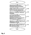
Figur 1, Figur 5- ein Flußdiagramm des erfindungsgemäßen Verfahrens im ersten Ausführungsbeispiel und
Figur 6- ein Flußdiagramm einer besonders bevorzugten Ausführungsform der Erfindung eines zweiten Ausführungsbeispiels.
- Figure 1
- a synchronous digital communication network,
- Figure 2
- a scheme with the multiplex structure of the communication network.
- Figure 3
- 2 shows a schematic representation of existing connections of a first multiplex layer in the message transmission network from FIG. 1,
- Figure 4
- 2 shows a schematic representation of existing connections of a second multiplex layer in the message transmission network from FIG. 1,
- Figure 5
- a flowchart of the inventive method in the first embodiment and
- Figure 6
- a flowchart of a particularly preferred embodiment of the invention of a second embodiment.
Ein synchrones digitales Nachrichtenübertragungssystem besteht üblicherweise aus einer Anzahl verschiedener, zu einem Nachrichtenübertragungsnetz verschalteter Netzelemente wie Add/Drop-Multiplexer (ADM) und Cross-Connect-Einrichtungen (CC). Die verschiedenen Netzelemente werden von mehreren (beispielsweise zwei) hierarchisch angeordneten Managementeinrichtungen M1, M2 gesteuert. Ein solches Nachrichtenübertragungsnetz ist in Figur 1 gezeigt. Dabei ist es üblich, daß mehrere Netzelemente jeweils zu Ringen (Ring A - Ring E) oder Teil netzen verschaltet sind. Mehrere Netzelemente gleichen Typs in jedem Ring oder Teilnetz werden von einer eigenen Managementeinrichtung M1 einer unteren Hirarchiestufe gesteuert, während eine Managementeinrichtung M2 einer oberen Hierarchiestufe für die Steuerung der Managementeinrichtung M1 der unteren Hirarchiestufe vorgesehen ist und das Zusammenspiel der einzelnen Ringe und Teil netze regelt. Verbindungen zwischen Netzelementen sind mit durchgezogenen Linien gezeichnet, Verbindungen zwischen der Managementeinrichtung M1 und den Netzelementen mit gestrichelten Linien und Verbindungen zwischen der Managementeinrichtung M2 und den Managementeinrichtungen M1 mit strichpunktierten Linien. Doppelpfeile bezeichnen die Zugangspunkte, an denen von außen auf des Netz zugegriffen werden kann oder an denen zu übertragende Nachrichten eingegeben werden. Cross-Connect-Einrichtungen sind mit CC bezeichnet, Add/Drop-Multiplexer sind als Dreiecke gezeichnet.A synchronous digital message transmission system usually exists from a number of different, to a message transmission network interconnected network elements such as add / drop multiplexers (ADM) and cross-connect devices (CC). The different network elements are from several (e.g. two) hierarchically arranged Management devices M1, M2 controlled. Such one Message transmission network is shown in Figure 1. It is common that several network elements each to form rings (ring A - ring E) or part are connected. Multiple network elements of the same type in each ring or Subnetworks are created by a separate management facility M1, a lower one Hierarchy level controlled, while a management facility M2 one upper hierarchy level for the control of the management device M1 lower hierarchy level is provided and the interaction of each Rings and part nets regulates. Connections between network elements are included solid lines drawn, connections between the Management device M1 and the network elements with dashed lines and connections between the management device M2 and the Management facilities M1 with dash-dotted lines. Double arrows denote the access points at which the network is accessed from outside can be entered or on which messages to be transmitted become. Cross-connect devices are designated CC, add / drop multiplexers are drawn as triangles.
Die Aufgaben der Managementeinrichtungen M1, M2 sind, das Netz zu konfigurieren, Verbindungen einzurichten und abzubauen, Wartung von Hardware und Software sowie die Behandlung von Ausnahmesituationen. Ein Grundgedanke der Erfindung besteht nun darin, Verbindungen ohne ein Mitwirken der Managementeinrichten M1, M2 aufzubauen. Das Nachrichtenübertragungsnetz erhält eine Anforderung, eine neue Verbindung aufzubauen, sucht und findet mittels des erfindungsgemäßen Verfahrens einen geeigneten Pfad durch das Netz und baut über diesen Pfad die geforderte Verbindung auf. Eine auf diese Weise neu eingerichtete Verbindung kann den Managementeinrichtungen anschließend mitgeteilt werden.The tasks of the management devices M1, M2 are the network too configure, set up and clear connections, maintenance of Hardware and software as well as the handling of exceptional situations. A The basic idea of the invention now consists in connections without one Participation of the management institutions M1, M2 to build up. The Message transmission network receives a request for a new connection to build up, seeks and finds one by means of the method according to the invention suitable path through the network and builds the required path via this path Connection on. A connection newly established in this way can Management facilities are then notified.
In dem Nachrichtenübertragungsnetz wird ein Protokoll verwendet, gemäß
dem das Netz in mehrere Multiplexschichten logisch strukturiert ist. In Figur 2
ist die Multiplexstruktur nach dem für synchrone digitale Hierarchie (SDH)
festgelegten Protokoll schematisch gezeigt, welches in den
Ausführungsbeispielen verwendet wird. Die grundlegende Übertragungseinheit
ist eine als synchrones Transportmodul STM-N bezeichnete Rahmenstruktur. N
steht für eine der Zahlen 1, 4, 16 oder ein größeres Vielfaches von 4 und
bezeichnet die Übertragungskapazität (Größe) des Transportmodules. Im
Ausführungsbeispiel werden nur Transportmodule der Größe STM-1
verwendet, die Erfindung ist jedoch mit jedem anderen Transportmodul
ebenfalls ausführbar. Ebenso ist die Erfindung nicht auf die Multiplexstruktur
von SDH beschränkt, vielmehr kann jedes andere Protokoll für synchrone
digtale Nachrichtenübertragungsnetze mit hierarchischer Multiplexstruktur
verwendet werden, wie beispielsweise das Protokoll für SONET (synchronous
optical network). A protocol is used in the communication network, according to
which the network is logically structured in several multiplex layers. In Figure 2
is the multiplex structure according to the for synchronous digital hierarchy (SDH)
shown protocol schematically, which in the
Embodiments is used. The basic transmission unit
is a frame structure called a synchronous transport module STM-N. N
stands for one of the
Ein Transportmodul vom Typ STM-1 kann einen virtueller Container VC-4 transportieren. In diesen wiederum können drei Untereinheitem vom Typ TUG-3 gepackt werden, die jeweils wieder sieben Untereinheiten vom Typ TUG-2 beinhalten können. Durch diese Multiplexstruktur ist das Nachrichtenübertragungsnetz logisch in die erwähnten Multiplexschichten STM-N, VC-4, TUG-3 und TUG-2 strukturiert. Näheres zu dieser Multiplexstruktur ist in ITU-T Recommendation G.707 (3/96) ausgeführt.A transport module of type STM-1 can have a virtual container VC-4 transport. In this in turn, three subunits of the type TUG-3 are packed, each again seven sub-units of the type TUG-2 may include. This is through this multiplex structure Message transmission network logically in the multiplex layers mentioned STM-N, VC-4, TUG-3 and TUG-2 structured. More about this Multiplex structure is implemented in ITU-T Recommendation G.707 (3/96).
Das erfindungsgemäße Verfahren basiert auf einem Modell des Nachrichtenübertragungsnetzes, das im folgenden anhand der Ausführungsbeispiele und der Figuren 3 und 4 erläutert wird, und der geschilderten Multiplexstruktur. Die Figuren 3 und 4 zeigen dasselbe Netz wie Figur 1.The method according to the invention is based on a model of the Communication network, which is based on the following Embodiments and Figures 3 and 4 is explained, and described multiplex structure. Figures 3 and 4 show the same network as Figure 1
In dem Modell werden zunächst die direkten, physikalischen Verbindungen zwischen den Netzelementen betrachtet. Diese sind in Figur 3 als Pfeile dargestellt. Es handelt sich bei diesen direkten, physikalischen Verbindungen um bestehende Verbindungen der untersten Multiplexschicht STM-N. Mit A sind die Zugangspunkte des Netzes bezeichnet, die in Figur 1 als Doppelpfeile gezeichnet waren. Add/Drop-Multiplexer sind in Figur 2 mit ADM bezeichnet, Cross-Connect-Einrichtungen mit CC. Da es sich bei den direkten, physikalischen Verbindungen um bidirektionale Verbindungen handelt, ist zwischen zwei miteinander verbundenen Netzelementen je ein Pfeil in jede Richtung gezeichnet. Managementeinrichtung des Nachrichtenübertragungsnetzes sind in den Figuren 3 und 4 nicht gezeigt.The direct, physical connections are first in the model considered between the network elements. These are shown as arrows in FIG. 3 shown. These are direct physical connections for existing connections of the lowest multiplex layer STM-N. With A are the access points of the network, which are shown in Figure 1 as double arrows were drawn. Add / drop multiplexers are designated ADM in FIG. 2, Cross-connect facilities with CC. Since the direct, physical connections are bidirectional connections an arrow in each between two interconnected network elements Drawn towards. Management facility of the Message transmission network are not shown in Figures 3 and 4.
Als nächstes werden logische Verbindungen zwischen zwei Netzelementen des Nachrichtenübertragungsnetzes betrachtet, die dadurch entstehen, daß virtuelle Container VC-4 von zwischen den zwei Netzelementen angeordneten Netzelementen durchgeschaltet werden. Diese logischen Verbindungen sind in Figur 4 dargestellt. Eine solche Durchschaltung von Untereinheiten synchroner Transportmodule ist üblicherweise eine Aufgabe der Cross-Connect-Einrichtungen. Bei den in Figur 3 dargestellten logischen Verbindungen handelt es sich um Verbindungen der zweiten Multiplexschicht VC-4. Analog lassen sich Graphen mit den logischen Verbindungen der höheren Multiplexschichten TUG-3 und TUG-2 zeichenen. Ebenso können unidirektionale Verbindungen, Punkt-zu-Mehrpunkt-Verbindungen (broadcasted connections) und geschützte Verbindungen, sogenannte subnetwork connection protection (SNCP), als Pfeile zwischen ihren jeweiligen Endpunkten in die Graphen eingezeichnet werden.Next, logical connections between two network elements of the Communication network considered that arise from the fact that virtual container VC-4 arranged between the two network elements Network elements are switched through. These logical connections are in Figure 4 shown. Such a switching of sub-units more synchronously Transport modules are usually a task of the cross-connect facilities. With the logical connections shown in FIG. 3 are connections of the second multiplex layer VC-4. Analogous graphs with the logical connections of the higher ones Multiplex layers TUG-3 and TUG-2 characters. You can also unidirectional connections, point-to-multipoint connections (broadcasted connections) and protected connections, so-called subnetwork connection protection (SNCP), as arrows between their respective End points are plotted on the graphs.
In dem Modell werden also alle bestehenden Verbindungen zwischen den Netzelementen des Nachrichtenübertragungsnetzes berücksichtigt, und zwar in allen Multiplexschichten. Dabei ist zu bemerken, daß eine Verbindung einer höheren Multiplexschicht, beispielsweise der Multiplexschicht VC-4, einen Pfad in der nächstniedrigeren Multiplexschicht darstellt, beispielsweise in der Multiplexschicht STM-N. Als Pfad wird eine Kette einzelner Verbindungen bezeichnet. Es besteht also eine einseitige Korrelation zwischen den Multiplexschichten und zwar von einer höheren Multiplexschicht zu einer niedrigeren, nicht jedoch umgekehrt.In the model, all existing connections between the Network elements of the message transmission network are taken into account, namely in all multiplex layers. It should be noted that a connection of a higher multiplex layer, for example the multiplex layer VC-4, a path in the next lower multiplex layer, for example in the Multiplex layer STM-N. A chain of individual connections is used as the path designated. So there is a one-sided correlation between the Multiplex layers and that from a higher multiplex layer to one lower, but not vice versa.
Die in dem Modell berücksichtigten Verbindungen, d.h. alle bestehenden Verbindungen in allen Multiplexschichten, werden im folgenden mit dem englischen Begriff Arc bezeichnet. Für jeden Arc kann eine freie Übertragungskapazität berechnet werden als Differenz aus der gesamten Übertragungskapazität eines Arcs, die in ITU-T Recommendation G.707 (3/96) für die jeweiligen Multiplexschichten festgelegt ist, und der momentanen Last des Arcs. Legt man nun alle Graphen aufeinander und berücksichtigt die freie Übertragungskapazität jedes einzelen Arcs, so erhält man einen vielschichtigen Graph, der alle momentan möglichen Pfade in dem Nachrichtenübertragungsnetz in allen Multiplexschichten widerspiegelt.The connections considered in the model, i.e. all existing Connections in all multiplex layers, in the following with the English term called Arc. For each arc there can be one free Transmission capacity can be calculated as the difference from the total Transmission capacity of an Arc, as described in ITU-T Recommendation G.707 (3/96) is defined for the respective multiplex layers, and the momentary load of the Arc. Now put all the graphs on top of each other and takes into account the free transmission capacity of each individual arc, so get you have a multilayered graph that shows all the currently possible paths in the Communication network reflected in all multiplex layers.
Basierend auf diesem Modell besteht ein weiterer Grundgedanke der Erfindung darin, von einem sendenden Netzelement einen Rundruf an alle übrigen Netzelemente abzuschicken, um mögliche Pfade für eine Verbindung zwischen dem sendenden Netzelement und einem ausgewählten Netzelemenent zu identifizieren. Dieser Rundruf soll über bestehende Verbindungen aller für die aufzubauende Verbindung in Frage kommenden Multiplexschichten übertragen werden, die ausreichend freie Übertragungskapclzitöt aufweisen. Erfindungsgemäß wird dazu in Netzelementen, die den Rundruf empfangen für zumindest einen Teil der Ausgänge des jeweiligen Netzelementes in allen für die Verbindung in Frage kommenden Multiplexschichten, auf die das jeweilige Netzelement Zugriff hat, geprüft, ob ausreichend freie Übertragungskapazität zur Verfügung steht. D.h. jedes Netzelement prüft die Arcs, die es terminiert auf freie Übertragungskapazität. Über geeignete Arcs wird der Rundruf dann von den betreffenden Netzelementen weitergeleitet. Erreicht ein Rundruf das ausgewählte Netzelement, so ist ein möglicher Pfad identifiziert.Based on this model there is another basic idea of Invention in broadcasting a broadcasting element to everyone send other network elements to possible paths for a connection between the sending network element and a selected one Identify network elements. This broadcast should be about existing ones Connections of all possible for the connection to be established Multiplex layers are transferred that are sufficiently free Have transmission capacity. According to the invention in Network elements that receive the broadcast for at least part of the Outputs of the respective network element in all for the connection in question upcoming multiplex layers to which the respective network element has access, checked whether sufficient free transmission capacity is available. I.e. each network element checks the arcs it terminates for free Transmission capacity. The broadcast will then be broadcast by the appropriate arcs forwarded network elements concerned. A broadcast reaches that selected network element, a possible path is identified.
Im folgenden wird anhand der Figur 5 das erfindungsgemäße Verfahren in einem ersten Ausführungsbeispiel detailliert beschrieben. Zunächst wird in einem ersten Schritt ST1 eine Verbindungsanforderung an einem Netzelement festgestellt. Dieses Netzelemenet wird dadurch zum sendenden Netzelement, das Netzelement, zu dem die Verbindung hergestellt werden soll zum ausgewählten Netzelement. Das sendende Netzelement prüft dann in einem zweiten Schritt ST2, welche der Multiplexschichten für die aufzubauende Verbindung geeignet sind. Dazu wird verglichen, wieviel Übertragungskapazität für die aufzubauende Verbindung benötigt wird und wieviel Übertragungskapazität ein Container oder Transportmodul der jeweiligen Multiplexschicht zur Verfügung stellt.The method according to the invention is shown in FIG a first embodiment described in detail. First in a first step ST1 a connection request to a network element detected. This network element thus becomes the sending network element, the network element to which the connection is to be made to selected network element. The sending network element then checks in one second step ST2, which of the multiplex layers for the to be built Connection are suitable. It is compared how much Transmission capacity is required for the connection to be set up and how much transmission capacity a container or transport module provides the respective multiplex layer.
In einem dritten Schritt ST3 verschickt das sendende Netzelement einen Rundruf an alle übrigen Netzelemente des Nachrichtenübertragungsnetzes. Vorteilhaft wird in dem Rundruf eine Verbindungsinformation übertragen, die angibt, welche der Multiplexschichten für den Aufbau der Verbindung geeignet sind. Dies kann z.B. auf die Art erfolgen, daß in dem Rundruf die für den Aufbau der Verbindung erforderliche Übertragungskapazität angegeben wird. Der Rundruf wird über alle bestehenden Verbindungen aller Multiplexschichten, auf die das sendende Netzelement Zugriff hat, die für den Aufbau der Verbindung geeignet sind und die genügend freie Übertragungskapazität aufweisen, ausgesendet. D.h. er wird über alle Arcs mit genügend freier Übertragungskapazität ausgesendet, die das sendende Netzelement terminiert. Das der Rundruf an alle übrigen Netzelemente verschickt wird, bedeutet nicht, daß alle übrigen Netzelemente zwangsläufig den Rundruf erhalten. Vielmehr bedeutet dies, daß als Zieladresse nicht ein bestimmtes Netzelement eingetragen ist, sondern die Zieladresse lautet: "an alle".In a third step ST3, the sending network element sends one Broadcast to all other network elements of the message transmission network. In the broadcast, connection information is advantageously transmitted indicates which of the multiplex layers is suitable for establishing the connection are. This can e.g. in such a way that in the broadcast the for the Establishing the connection required transmission capacity is specified. The broadcast is over all existing connections of everyone Multiplex layers to which the sending network element has access, that for the Establishing the connection are suitable and the enough free Have transmission capacity sent out. I.e. he will be with all arcs enough free transmission capacity is sent out by the sending Network element terminated. This is the broadcast to all other network elements sent, does not mean that all other network elements are inevitable receive the broadcast. Rather, this means that the destination address is not one specific network element is entered, but the target address is: "to all".
In einem vierten Schritt ST4 leiten Netzelemente, die den Rundruf empfangen, diesen über geeignete Arcs weiter. Hierzu kann in jedem empfangenden Netzelement wiederum für jede geeignete Multiplexschicht an jedem Ausgang geprüft werden, ob ein Pfad mit freier Übertragungskapazität besteht. Vorteilhaft ist, den Rundruf nur über solche Pfade weiterzuleiten. Es kann auch vorgegeben sein, daß alle oder nur bestimmte Rundrufe über bestimmte Ausgänge oder Arcs nicht weiterzuleiten sind. Weiter ist es vorteilhaft, in Abhängigkeit eines weiteren Kriterium wie beispielsweise einer in dem Netzelement gespeicherten Routing-Tabelle, den Rundruf über bestimmte Arcs nicht weiterzuleiten. So kann in der Routing-Tabelle bezeichnet sein, daß ein Rundruf mit einer bestimmten Zieladresse über bestimmte Arcs nicht weitergeleitet zu werden braucht, da über diese Arcs kein Pfad zu dem ausgewählten Netzelement gefunden werden kann, beispielsweise weil der Arc vom Ziel weg führt.In a fourth step ST4, network elements that receive the broadcast direct this via suitable arcs. This can be done in each receiving Network element in turn for each suitable multiplex layer at each output check whether there is a path with free transmission capacity. It is advantageous to only forward the broadcast via such paths. It can also be specified that all or only certain broadcasts over certain Outputs or arcs are not to be forwarded. Furthermore, it is advantageous in Dependence on another criterion such as one in the Network element stored routing table, the broadcast over certain arcs not forward. For example, the routing table can indicate that a Broadcasting to a specific destination via specific arcs is not needs to be forwarded as there is no path to the via these arcs selected network element can be found, for example because of the Arc leads away from the goal.
Auf diese Weise wird der Rundruf in dem Nachrichtenübertragungsnetz über verschiedene Pfade weitergeleitet. Erreicht der Rundruf über einen ersten Pfad das ausgewählte Netzelement, so ist dieser erste Pfad als für den Verbindungsaufbau geeignet identifiziert. Das ausgewählte Netzelement kann nun einen Timer starten und eine vorgegebene Zeitspanne auf weitere Rundrufe, die über andere Pfade übertragen werden, warten. Ist die Zeitspanne abgelaufen, so wird ein einem fünften Schritt ST5 einer der als geeignet identifizierten Pfade für den Verbindungsaufbau ausgewählt. In einem sechsten Schritte ST6 wird die gewünschte Verbindung dann über den ausgewählten Pfad ausgebaut. Dies erfolt vorteilhaft von dem ausgewählten Netzelement aus. In this way, the broadcast in the communication network is over different paths forwarded. The broadcast reaches via a first path the selected network element, this is the first path as for the Appropriately identified connection establishment. The selected network element can now start a timer and a specified period of time for others Broadcasts that are transmitted on other paths are waiting. Is the Time period has elapsed, then a fifth step ST5 becomes one of the as appropriately identified paths selected for the connection establishment. In A sixth step ST6 is the desired connection via the selected path expanded. This is advantageously done by the selected one Network element.
Bei einer vorteilhaften Weiterbildung der Erfindung wird in dem Rundruf ein Kostenparameter übertragen. Jedes Netzelement, das den Rundruf weiterleitet, berechnet die bei ihm anfallenden Verbindungskosten und addiert sie zu dem Kostenparameter. Das ausgewählte Netzelement kann dann aufgrund dieses Kostenparameters entscheiden, welche der identifizierten Pfade für den Verbindungsaufbau am kostengünstigsten ist und diesen auswählen. Die Berechnung der Verbindungskosten erfolgt in Abhängigkeit der momentanen Nutzung der Verbindungen und Netzelemente. Ein Arc, der nur noch wenig freie Übertragunsgkapazität aufweist ist teurer als ein freier oder fast freier Arc. Ein ausgelasteter Arc erhält als Kostenparameter den Wert Unendlich. Es können auch weitere Kriterien für die Berechnung des Kostenparameters herangezogen werden, wie die Anzahl der in einem Pfad liegenden Netzelemente oder eine vom Netzbetreiber angestebte Lastverteilung im Netz.In an advantageous development of the invention, a is in the broadcast Transfer cost parameters. Every network element that forwards the broadcast calculates the connection costs incurred by him and adds them to that Cost parameters. The selected network element can then be based on this Cost parameters decide which of the identified paths for the Establishing a connection is the cheapest and select it. The The connection costs are calculated depending on the current one Use of connections and network elements. An arc that has little left Free transmission capacity is more expensive than a free or almost free one Arc. A busy arc receives the value infinity as a cost parameter. It can also use other criteria for calculating the cost parameter can be used as the number of lying in a path Network elements or a load distribution in the network sought by the network operator.
Im folgenden wird aufbauend auf dem ersten Ausführungsbeispiel anhand des
Flußdiagrammes aus Figur 6 eine besonders bevorzugte Ausführung des
erfindungsgemäßen Verfahrens in einem zweiten Ausführungsbeispiel
erläutert. Hierzu werden in dem zweiten Ausführungsbeispiel nur die beiden
untersten Multiplexschichten STM-N und VC-4 betrachtet. Für die höheren
Multiplexschichten TUG-3 und TUG-2 ist das Verfahren jedoch analog
anzuwenden.
Entsprechend den Schritte S3 bis S12 wird der Rundruf an allen
zwischengeschalteten Netzelementen empfangen und über geeignete Arcs
weitergeleitet. Dadurch gelangt der Rundruf über verschiedene Pfade zu dem
ausgewählten Netzelement 6. Dies können z.B. die Pfade 1-2-3-4-5-6,
1-2'-2-3-3'-3"-4-5-6 oder 1-5-6 sein. Am ausgewählten Netzelement 6
werden nun folgende Schritte durchgeführt:
Bei einer weiteren vorteilhaften Ausführung der Erfindung besitzt jeder Rundruf eine eindeutige Vorgangsnummer. Empfängt ein Netzelement, welches einen ersten Rundruf bereits weitergeleitet hat, einen weiteren Rundruf mit derselben Vorgangsnummer, so bestehen zwei Möglichkeiten: Entweder verwirft es den weiteren Rundruf, wenn dessen Kostenparameter höher ist als der Kostenparameter des ersten Rundrufes, oder es gibt die aufgrund des ersten Rundrufes blockierte Übertragungskapazität frei, leitet den zweiten Rundruf weiter und blockiert die Übertragungskapazität auf dem zum Weiterleiten genutzten Pfad, wenn der Kostenparameter des ersten Rundrufes höher ist als der Kostenparameter des weiteren. Auf diese Weise wird die Bildung von Schleifen wirkungsvoll verhindert.In a further advantageous embodiment of the invention, each broadcast has a unique transaction number. Receives a network element, which one has already forwarded the first broadcast, another broadcast with the same Case number, there are two options: either it discards the further broadcast if its cost parameter is higher than that Cost parameters of the first broadcast, or there are those based on the first Broadcast blocked transmission capacity free, forwards the second broadcast further and blocks the transmission capacity on the for forwarding Path used if the cost parameter of the first broadcast is higher than the cost parameter further. In this way the formation of Grinding effectively prevented.
Ein Protokoll, das zur Signalisierung zwischen den Netzelementen des
Nachrichtenübertragungsnetzes zur Ausführung des erfindungsgemäßen
Verfahrens verwendet werden kann, wird im folgenden beschrieben. Es legt
die Form des Rundrufes fest, der zwischen den Netzelementen ausgetauscht
wird. Der Rundruf hat folgende Form:
- TransactionIndex:
- Eindeutige Vorgangsnummer des Rundrufes;
- MessageType:
- Art und Zweck des Rundrufes, hier Rundruf zum Aufbau einer Verbindung;
- SourceNode:
- Adresse des sendenden Netzknotens;
- DestinationNode:
- Adresse des ausgewählten Netzknotens;
- ConnectionType:
- Art der aufzubauenden Verbindung und benötigte Übertragungskapazität;
- ArcListOfPath:
- Liste, in die jedes weiterleitende Netzelement seine Adresse einträgt, bevor es den Rundruf weiterleitet;
- PathCost:
- Kostenparameter des Pfades, über den der Rundruf übertragen wird.
- TransactionIndex:
- Unique process number of the broadcast;
- MessageType:
- Type and purpose of the broadcast, here broadcast to establish a connection;
- SourceNode :
- Address of the sending network node;
- DestinationNode :
- Address of the selected network node;
- ConnectionType:
- Type of connection to be established and required transmission capacity;
- ArcListOfPath :
- List in which each forwarding network element enters its address before forwarding the broadcast;
- PathCost:
- Cost parameters of the path over which the broadcast is transmitted.
Der Rundruf wird vorzugsweise im sogenannten DCC übertragen, einem für SDH-Netze als Byte in der Kopfinformation von SDH-Rahmen festgelegten Dienstkanal.The broadcast is preferably transmitted in the so-called DCC, one for SDH networks defined as bytes in the header information of SDH frames Service channel.
Der zweite Rundruf, der von dem ausgewählten Netzelement zurückgesendet wird, wird MessageType=DeBlockPorts gesetzt, um anzuzeigen das der Zweck des zweiten Rundrufes ist, die blockierte Übertragungskapazität wieder freizugeben. Die Blockierung in den Netzelementen ist mit der eindeutigen Vorgangsnummer, der Transaktionsnummer verknüpft und diese ist bei dem ersten und dem zweiten Rundruf gleich.The second broadcast that is sent back by the selected network element is set to MessageType = DeBlockPorts to indicate that the purpose of the second broadcast is to release the blocked transmission capacity again. The blocking in the network elements is linked to the unique process number, the transaction number and this is the same for the first and the second broadcast.
Wenn ein Netzelement einen empfangenen Rundruf verwirft, beispielsweise weil bereits ein Rundruf mit der gleichen Transaktionsnummer und niedrigerem Kostenparameter eingegangen und bearbeitet ist, so ist es vorteilhaft, wenn es den zu verwerfenden Rundruf zuvor mit MessageType=DeBlockPorts zurückschickt. Dadurch werden blockierte Übertragungskapazitäten schnellst möglich wieder freigegeben. If a network element rejects a received broadcast, for example because a broadcast has already been received and processed with the same transaction number and lower cost parameter, it is advantageous if it sends the broadcast to be rejected beforehand with MessageType = DeBlockPorts . Blocked transmission capacities will be released as soon as possible.
Ein besonderer Vorteil des erfindungsgemäßen Verfahrens besteht darin, daß ein Einschränken der für die Pfadsuche zugelassenen Multiplexschichten möglich ist. Dies kann für den Aufbau von virtuellen privaten Netzen von Interesse sein. Ein Netzwerkanbieter kann dadurch seinem Kunden ein virtuelles Netz zur Verfügung stellen, das der Kunde beispielsweise auf den Multiplexschichten TUG-2 und TUG-3 nach eigenen Wünschen konfigurieren kann. Der Zugang zu den darunterliegenden Multiplexschichten bleibt dem Kunden jedoch verwehrt. Für den Kunden liegt dann ein transparentes Netz vor, das er nach eigenem Ermessen konfigurieren kann. Der Netzwerkbetreiber braucht sich um die Konfigurationswünsche seines Kunden nicht mehr zu kümmern.A particular advantage of the method according to the invention is that restricting the multiplex layers permitted for path search is possible. This can be used for building virtual private networks from Be interested. This enables a network provider to serve its customer provide a virtual network that the customer can access, for example Configure multiplex layers TUG-2 and TUG-3 according to your own wishes can. Access to the underlying multiplex layers remains However, customers are denied. A transparent network is then available for the customer that he can configure at his own discretion. Of the Network operator needs the configuration requests of its customer no longer care.
Ein Netzelement, das zur Durchführung des erfindungsgemäßen Verfahrens geeignet ist, verfügt über folgende Vorrichtungen:
- Mittel zum Feststellen einer Verbindungsanforderung,
- Mittel zum Prüfen, welche der Multiplexschichten für den Verbindungsaufbau geeignet sind,
- Mittel zum Bestimmen einer freien Übertragungskapazität für bestehende Verbindungen der geeigneten Multiplexschichten,
- Mittel zum Verschicken des Rundrufs und
- Mittel zum Weiterleiten eines empfangenen Rundrufes.
- Means for determining a connection request,
- Means for checking which of the multiplex layers are suitable for establishing the connection,
- Means for determining a free transmission capacity for existing connections of the appropriate multiplex layers,
- Means for sending the broadcast and
- Means for forwarding a received broadcast.
Das Netzelement besitzt vorteilhaft einen Prozessor, der für die Abwicklung der Verbindungswünsche zuständig ist, und einen diesem Prozessor zugeordneten Speicher. Dies bedeutet, daß alle Rundrufe und Nachrichten, die mit dem Aufbau von Verbindungen zu tun haben, von diesem Prozessor bearbeitet werden. Der Prozessor kennt alle Verbindungen, die mit seinem Netzelement zu tun haben, d.h. alle Arcs, die das Netzelement terminiert. Anhand der bereits bestehenden Verbindungen können mittels eines entsprechenden Softwaremoduls die möglichen Pfade aus Sicht des Netzelementes errechnet werden. Ist z.B. für einen Verbindungsaufbau kein nutzbarer VC-4 mit freier Übertragungskapazität vorhanden, so wird einer reserviert und beim Verbindungsaufbau aufgebaut. Der Prozessor hat vorteilhafterweise direkten Zugriff auf die Kommunikationskanäle des Netzelementes.The network element advantageously has a processor that is used to process the Connection requests is responsible, and one assigned to this processor Storage. This means that all broadcasts and messages with the Connections have to be processed by this processor become. The processor knows all connections with its network element have to do, i.e. all arcs that the network element terminates. Based on already existing connections can be made using an appropriate Software module calculates the possible paths from the point of view of the network element become. Is e.g. no usable VC-4 with free for establishing a connection Transmission capacity available, one is reserved and at Established connection. The processor advantageously has a direct one Access to the communication channels of the network element.
Besonders vorteilhaft ist es, wenn der Prozessor sich aus den Informationen, die er mittels der Rundrufe erhält, eine Liste der möglichen weitergehenden Pfade aufbaut. Eine solche Liste wird als Routing-Tabelle bezeichnet. Auf Anfrage, d.h. wenn eine Verbindungsanforderung vorliegt oder ein Rundruf empfangen wird, braucht er die Liste nur aus dem Speicher zu lesen und erhält daraus Informationen, über welche Arcs ein Rundruf abzuschicken oder weiterzuleiten ist. Eine solche Routing-Tabelle kann auch über eine Managementeinrichtung erstellt, aktualisiert und verteilt werden. Weiter ist es möglich, daß die Netzelemente ihre Routing-Tabellen untereinander austauschen und abgleichen.It is particularly advantageous if the processor is composed of the information which he receives through the broadcasts, a list of possible further ones Builds paths. Such a list is called a routing table. On Request, i.e. when there is a connection request or a broadcast received, he only needs to read the list from the memory and receives information about which arcs are used to send a broadcast or is to be forwarded. Such a routing table can also have a Management facility created, updated and distributed. It is further possible that the network elements share their routing tables exchange and compare.
Claims (16)
dadurch gekennzeichnet,
characterized,
Applications Claiming Priority (2)
| Application Number | Priority Date | Filing Date | Title |
|---|---|---|---|
| DE19801875A DE19801875A1 (en) | 1998-01-20 | 1998-01-20 | Method for establishing a connection in a synchronous digital communication network and network element |
| DE19801875 | 1998-01-20 |
Publications (2)
| Publication Number | Publication Date |
|---|---|
| EP0930739A2 true EP0930739A2 (en) | 1999-07-21 |
| EP0930739A3 EP0930739A3 (en) | 2005-05-11 |
Family
ID=7855075
Family Applications (1)
| Application Number | Title | Priority Date | Filing Date |
|---|---|---|---|
| EP99440006A Withdrawn EP0930739A3 (en) | 1998-01-20 | 1999-01-19 | Method for setting up a connection in a synchronous digital communications network and network element |
Country Status (4)
| Country | Link |
|---|---|
| US (1) | US6714518B1 (en) |
| EP (1) | EP0930739A3 (en) |
| CA (1) | CA2257567A1 (en) |
| DE (1) | DE19801875A1 (en) |
Families Citing this family (5)
| Publication number | Priority date | Publication date | Assignee | Title |
|---|---|---|---|---|
| JP2004503011A (en) * | 2000-07-05 | 2004-01-29 | アーンスト & ヤング エルエルピー | Method and apparatus for providing computer services |
| DE60332503D1 (en) * | 2003-08-05 | 2010-06-17 | Telecom Italia Spa | METHOD FOR PROVIDING EXTRA TRAFFIC ROUTES WITH CONNECTION PROTECTION IN A COMMUNICATION NETWORK, THIS NETWORK AND COMPUTER PROGRAM PRODUCT THEREFOR |
| US7391720B1 (en) * | 2004-02-02 | 2008-06-24 | Ciena Corporation | Local span mesh restoration (LSMR) |
| US7847174B2 (en) * | 2005-10-19 | 2010-12-07 | Yamaha Corporation | Tone generation system controlling the music system |
| US8352537B2 (en) * | 2008-09-08 | 2013-01-08 | Futurewei Technologies, Inc. | Object modeling scheme for next generation network wavelength division multiplexing |
Citations (2)
| Publication number | Priority date | Publication date | Assignee | Title |
|---|---|---|---|---|
| US5065399A (en) * | 1988-11-24 | 1991-11-12 | Bell Communications Research, Inc. | Telecommunication network trouble recovery system |
| US5712968A (en) * | 1991-07-08 | 1998-01-27 | Hitachi, Ltd. | System for establishing new path in ring network and dividing ring shaped path into plurality of ring shaped paths by being rid of faulty path |
Family Cites Families (11)
| Publication number | Priority date | Publication date | Assignee | Title |
|---|---|---|---|---|
| JP3071007B2 (en) * | 1991-10-22 | 2000-07-31 | 富士通株式会社 | Communication network control method |
| DE4343839A1 (en) * | 1993-12-22 | 1995-06-29 | Philips Patentverwaltung | Local network with data exchange via radio transmission paths |
| DE4407544C2 (en) * | 1994-03-07 | 1996-05-30 | Ulrich Altvater | Method for transmitting data packet sets and terminal therefor |
| US5495471A (en) * | 1994-03-09 | 1996-02-27 | Mci Communications Corporation | System and method for restoring a telecommunications network based on a two prong approach |
| SE515058C2 (en) * | 1994-10-04 | 2001-06-05 | Telia Ab | Device for controlling the capacity of a telecommunications network |
| US5815490A (en) * | 1995-11-20 | 1998-09-29 | Nec America, Inc. | SDH ring high order path management |
| US5884017A (en) * | 1995-12-29 | 1999-03-16 | Mci Communications Corporation | Method and system for optical restoration tributary switching in a fiber network |
| DE19608621C2 (en) * | 1996-03-06 | 1998-03-19 | Nokia Telecommunications Oy | Telecommunications network |
| US5872523A (en) * | 1996-03-12 | 1999-02-16 | Motorola, Inc. | Target device and method for establishing a communication path in a networked communications system |
| US6256292B1 (en) * | 1996-07-11 | 2001-07-03 | Nortel Networks Corporation | Self-healing line switched ring for ATM traffic |
| US6052722A (en) * | 1997-03-07 | 2000-04-18 | Mci Communications Corporation | System and method for managing network resources using distributed intelligence and state management |
-
1998
- 1998-01-20 DE DE19801875A patent/DE19801875A1/en not_active Withdrawn
-
1999
- 1999-01-18 CA CA002257567A patent/CA2257567A1/en not_active Abandoned
- 1999-01-19 EP EP99440006A patent/EP0930739A3/en not_active Withdrawn
- 1999-01-19 US US09/233,124 patent/US6714518B1/en not_active Expired - Fee Related
Patent Citations (2)
| Publication number | Priority date | Publication date | Assignee | Title |
|---|---|---|---|---|
| US5065399A (en) * | 1988-11-24 | 1991-11-12 | Bell Communications Research, Inc. | Telecommunication network trouble recovery system |
| US5712968A (en) * | 1991-07-08 | 1998-01-27 | Hitachi, Ltd. | System for establishing new path in ring network and dividing ring shaped path into plurality of ring shaped paths by being rid of faulty path |
Also Published As
| Publication number | Publication date |
|---|---|
| CA2257567A1 (en) | 1999-07-20 |
| EP0930739A3 (en) | 2005-05-11 |
| US6714518B1 (en) | 2004-03-30 |
| DE19801875A1 (en) | 1999-07-22 |
Similar Documents
| Publication | Publication Date | Title |
|---|---|---|
| DE60200530T2 (en) | Mechanism and method for determining and quickly restoring a minimum capacity in a meshed network | |
| DE69735084T2 (en) | Routing methods in hierarchical structured networks | |
| DE4430993C1 (en) | Adaptive path search among network nodes maintaining topological data | |
| DE69637290T2 (en) | Connection reservation in communication networks | |
| DE60116879T2 (en) | APPARATUS AND METHOD FOR OPTICAL COMMUNICATION PROTECTION | |
| DE69728630T2 (en) | Process and system for increasing the service quality at or below a limit tariff | |
| DE60022602T2 (en) | Method, device and computer program for keeping topology data of a link state routing network up to date | |
| DE69732676T2 (en) | Self-healing network, and switching method for transmission lines and transmission equipment therefor | |
| DE60011719T2 (en) | A method of sending routing data through a network and network node using the method | |
| DE69738175T2 (en) | Link transmission network | |
| DE69924345T2 (en) | Method and network node for improved routing and reservation protocol | |
| DE69816053T2 (en) | Telecommunications network with congestion control | |
| EP0902600B1 (en) | Method for establishing logical connections in a synchronous digital data communication network , network element and management system | |
| DE60319502T2 (en) | Process for the rebuilding of transport networks | |
| DE2603262B2 (en) | DEVICE FOR THE TRANSMISSION OF DATA | |
| DE69731469T2 (en) | ATM TELECOMMUNICATIONS SYSTEM AND METHOD FOR CONDUCTING DIRECT BELT TRAFFIC | |
| DE69819088T2 (en) | alternate routing | |
| EP0871344A2 (en) | Local network with reconfiguring capabilities in case of break of a line or failure of a node | |
| EP0579980B1 (en) | ATM communication system | |
| DE60206338T2 (en) | Connection establishment strategies in optical transport networks | |
| EP0930739A2 (en) | Method for setting up a connection in a synchronous digital communications network and network element | |
| DE60119848T2 (en) | Multiprocessor control block for use in an exchange and corresponding method | |
| DE69530340T2 (en) | Method and equipment for real-time management of means of communication in a virtual private network using ATM technology | |
| DE60204086T2 (en) | Distributed wavelength allocation with minimal contention in optical transport networks | |
| EP1313347A1 (en) | Routing in transport networks |
Legal Events
| Date | Code | Title | Description |
|---|---|---|---|
| PUAI | Public reference made under article 153(3) epc to a published international application that has entered the european phase |
Free format text: ORIGINAL CODE: 0009012 |
|
| AK | Designated contracting states |
Kind code of ref document: A2 Designated state(s): AT BE CH CY DE DK ES FI FR GB GR IE IT LI LU MC NL PT SE |
|
| AX | Request for extension of the european patent |
Free format text: AL;LT;LV;MK;RO;SI |
|
| PUAL | Search report despatched |
Free format text: ORIGINAL CODE: 0009013 |
|
| AK | Designated contracting states |
Kind code of ref document: A3 Designated state(s): AT BE CH CY DE DK ES FI FR GB GR IE IT LI LU MC NL PT SE |
|
| AX | Request for extension of the european patent |
Extension state: AL LT LV MK RO SI |
|
| RIC1 | Information provided on ipc code assigned before grant |
Ipc: 7H 04J 3/08 B Ipc: 7H 04L 12/56 B Ipc: 7H 04L 12/437 B Ipc: 7H 04Q 3/00 B Ipc: 7H 04J 3/12 A |
|
| STAA | Information on the status of an ep patent application or granted ep patent |
Free format text: STATUS: THE APPLICATION IS DEEMED TO BE WITHDRAWN |
|
| AKX | Designation fees paid |
Designated state(s): DE FI FR GB IT SE |
|
| 18D | Application deemed to be withdrawn |
Effective date: 20050801 |