EP0932069A1 - Reversible optical isolator for optical networks and amplifier - Google Patents
Reversible optical isolator for optical networks and amplifier Download PDFInfo
- Publication number
- EP0932069A1 EP0932069A1 EP98118664A EP98118664A EP0932069A1 EP 0932069 A1 EP0932069 A1 EP 0932069A1 EP 98118664 A EP98118664 A EP 98118664A EP 98118664 A EP98118664 A EP 98118664A EP 0932069 A1 EP0932069 A1 EP 0932069A1
- Authority
- EP
- European Patent Office
- Prior art keywords
- optical
- polarization
- light
- isolator
- reversible
- Prior art date
- Legal status (The legal status is an assumption and is not a legal conclusion. Google has not performed a legal analysis and makes no representation as to the accuracy of the status listed.)
- Withdrawn
Links
Images


Classifications
-
- G—PHYSICS
- G02—OPTICS
- G02F—OPTICAL DEVICES OR ARRANGEMENTS FOR THE CONTROL OF LIGHT BY MODIFICATION OF THE OPTICAL PROPERTIES OF THE MEDIA OF THE ELEMENTS INVOLVED THEREIN; NON-LINEAR OPTICS; FREQUENCY-CHANGING OF LIGHT; OPTICAL LOGIC ELEMENTS; OPTICAL ANALOGUE/DIGITAL CONVERTERS
- G02F1/00—Devices or arrangements for the control of the intensity, colour, phase, polarisation or direction of light arriving from an independent light source, e.g. switching, gating or modulating; Non-linear optics
- G02F1/01—Devices or arrangements for the control of the intensity, colour, phase, polarisation or direction of light arriving from an independent light source, e.g. switching, gating or modulating; Non-linear optics for the control of the intensity, phase, polarisation or colour
- G02F1/09—Devices or arrangements for the control of the intensity, colour, phase, polarisation or direction of light arriving from an independent light source, e.g. switching, gating or modulating; Non-linear optics for the control of the intensity, phase, polarisation or colour based on magneto-optical elements, e.g. exhibiting Faraday effect
- G02F1/093—Devices or arrangements for the control of the intensity, colour, phase, polarisation or direction of light arriving from an independent light source, e.g. switching, gating or modulating; Non-linear optics for the control of the intensity, phase, polarisation or colour based on magneto-optical elements, e.g. exhibiting Faraday effect used as non-reciprocal devices, e.g. optical isolators, circulators
-
- H—ELECTRICITY
- H01—ELECTRIC ELEMENTS
- H01S—DEVICES USING THE PROCESS OF LIGHT AMPLIFICATION BY STIMULATED EMISSION OF RADIATION [LASER] TO AMPLIFY OR GENERATE LIGHT; DEVICES USING STIMULATED EMISSION OF ELECTROMAGNETIC RADIATION IN WAVE RANGES OTHER THAN OPTICAL
- H01S3/00—Lasers, i.e. devices using stimulated emission of electromagnetic radiation in the infrared, visible or ultraviolet wave range
- H01S3/05—Construction or shape of optical resonators; Accommodation of active medium therein; Shape of active medium
- H01S3/06—Construction or shape of active medium
- H01S3/063—Waveguide lasers, i.e. whereby the dimensions of the waveguide are of the order of the light wavelength
- H01S3/067—Fibre lasers
- H01S3/06754—Fibre amplifiers
Definitions
- the present invention relates to data communication systems based on light signals and more particularly, to amplifiers and isolators for operating on light signals in optical networks.
- Communication networks based on optical fibers are becoming increasingly popular because of their high data transmission capacities and the low cost of the optical fibers.
- a number of users communicate with one another over an optical fiber arranged in a loop by sending signals along the fiber in a predetermined direction.
- each subscriber communicates with a central office over a fiber that is arranged in a ring with the subscriber and central office stations disposed along the ring. If the fiber is broken, communication between one or more of the users and the central office will be interrupted. In principle, these users can still communicate with the central office by sending messages along the uninterrupted portion of the loop. However, this requires that the direction of propagation along the fiber be reversed over a portion of the fiber.
- the fiber ring typically includes components that are unidirectional in nature such as optical amplifiers and isolators.
- a typical optical amplifier consists of a doped fiber between two optical isolators that prevent light generated in the doped fiber from propagating in the backward direction around the fiber.
- duplicate optical isolators configured to propagate signals in the opposite direction are included in the network.
- These components are inserted into the fiber in place of the corresponding components by utilizing bypass switches.
- Such bypass arrangements substantially increase the cost and complexity of the optical network, and hence, it would be advantageous to avoid these bypass arrangements.
- the present invention is a reversible optical isolator and an optical amplifier based on the optical isolator.
- the reversible isolator is constructed from a Faraday rotator having a magnetic field direction that is determined by a control signal applied thereto.
- the Faraday rotator is sandwiched between first and second polarization filters.
- the polarization filters are constructed from polarization splitters in series with half-wave plates.
- the allowed direction of propagation of an optical signal through the reversible optical amplifier is determined by the magnetic field direction in the Faraday rotator.
- An optical amplifier according to the present invention includes an optical gain element in series with one or two reversible optical isolators.
- an optical isolator will be defined to be any device having an input port and an output port in which a light signal entering the input port will exit through the output port; while a light signal entering the output port will be blocked from exiting the input port.
- a reversible optical isolator is defined to be an optical isolator having first and second ports in which one of the first and second ports is the input port and the other is the output port, the assignment of the input port being determined by a signal applied to the isolator.
- the present invention makes use of a Faraday rotator having a magnetic field whose direction is determined by the application of an external signal.
- a Faraday rotator is an element that is composed of an optically active compound such as yttrium-iron-garnet Y 3 Fe 5 O 12 which turns the direction of the polarization vector of the light passing therethrough by an angle of 45°.
- the direction of rotation is determined by the direction of an applied magnetic field.
- the direction of rotation of the polarization vector is independent of the direction of travel of the light through the element. By altering the direction of the magnetic field, the rotation of the polarization vector changes from 45° to -45° independent of the direction of travel of the light through device.
- a reversible optical isolator is constructed from a Faraday rotator having a reversible magnetic field
- Isolator 10 is constructed from two polarization filters shown at 12 and 16 and a Faraday rotator 14.
- polarization filter 12 is assumed to pass light which is polarized in a direction parallel to the y-axis, and polarization filter 16 passes light whose polarization is at 45° to the y-axis as indicated by the arrow on polarization filter 16.
- Light entering the input of isolator 10 is assumed to have at least some intensity along the y-axis. If the light has a polarization vector that is at an angle to the y-axis, the component of the light having a polarization parallel to the x-axis will be removed by polarization filter 12; hence, only the light having a polarization vector parallel to the y-axis needs be considered.
- This light leaves polarization filter 12 and passes through Faraday rotator 14, which rotates the polarization vector through 45° as shown at 15. The direction of polarization now matches the pass direction of polarization filter 16, and hence, the light exits through the output port.
- Polarization filter 16 selects the component of the polarization that is at 45° to the y-axis. Any light having a polarization at right angles to this direction is removed by polarization filter 16. Hence, only light having a polarization selected by polarization filter 16 needs to be considered.
- the output of polarization filter 16 is rotated through 45° by Faraday rotator 14, since the direction of rotation is independent of the direction of travel of light through the rotator. Hence, the light leaving Faraday rotator 14 will now be parallel to the x-axis as shown at 17. This light will be blocked by polarization filter 12; hence, no light can pass through isolator 10 in the reverse direction.
- Faraday rotator 14 will rotate the polarization of the light passing therethrough by -45° independent of the direction of travel of the light relative to the z-axis of the coordinate system shown in the figures.
- light entering the input end of isolator 10 will first pass through polarization filter 16 which selects the component of the light at 45° to the x-axis. Any polarization component at 90° to this direction is removed by polarization filter 16; hence, only the component at 45° needs to be considered.
- a reversible optical isolator can be constructed from a Faraday rotator in which the magnetic field applied to the material in the Faraday rotator can be reversed in response to signal that is applied to the isolator.
- Figure 5 is a cross-sectional view of a reversible optical isolator 100.
- Isolator 100 has a first port 121 which includes an optical guide 102 and a collimating/imaging lens 103 for collimating the light received on guide 102 or imaging light from polarization filter 104 back into guide 102.
- a similar arrangement is utilized for a second port 122, which includes an optical guide 107 and collimating/imaging lens 106.
- Polarization filter 104 has a pass orientation that differs from that of polarization filter 105 by 45°
- a Faraday rotator 123 rotates the polarization angle of the light that passes between polarization filters 104 and 105 by ⁇ 45° depending on the direction of the magnetic field.
- the direction of the magnetic field is determined by the current passing through coil 110, which generates a magnetic field having a component that is parallel to the direction of travel of the light between filters 104 and 105.
- the current is provided by current source 109, which sets the direction of the current in response to direction control signal.
- the direction control signal may be electrical or optical.
- a current pulse sets the direction of magnetization. The direction remains the same until another current pulse is applied.
- a permanent magnet together with a device for flipping the direction of the magnet in response to a control signal could also be utilized.
- FIG. 6 is a schematic view of a reversible isolator 150 according to the present invention which accepts light on any polarization and passes the light without losses other than those associated with absorption in the optical components.
- Isolator 150 utilizes two non-reciprocal polarization rotators to accomplish the isolation.
- Each non-reciprocal polarization rotator consists of a reversible Faraday rotator in series with a half-wave plate.
- the direction of rotation of the polarization vector provided by the Faraday rotator is the same regardless of the direction of travel of the light therethrough.
- the half-wave plate in contrast, provides either a 45° or -45° rotation depending on the direction of travel of the light. As a result, in one direction the polarization vector is rotated through 90°, and in the other, it is rotated through 0°.
- a polarization beam splitter 181 decomposes the polarization vector 191 of the incoming light into orthogonal components shown at 192 and 194.
- the polarization beam splitters are constructed from prisms that selectively reflect light of a predetermined polarization while passing light of the orthogonal polarization.
- the polarization component reflected by splitter 181 is reflected by mirror 171 into reversible Faraday rotator 162, which rotates the polarization by 45°.
- Half-wave plate 163 rotates the polarization vector by another 45° as shown at 195. This polarization passes through polarization splitter 182.
- splitter 181 The component of the input light that passed through splitter 181 is shown at 192. This component is likewise rotated through a total of 90° by reversible Faraday rotator 164 and half-wave plate 165. The output of half-wave plate 165 is reflected into splitter 182 by mirror 172. This polarization is reflected by splitter 182 into lens 154 where it is combined with the output of half-wave plate 163 discussed above to reconstitute the input light as shown at 196.
- FIG 7 illustrates the manner in which light entering port 155 is blocked from exiting via port 152 by beam splitter 181.
- the combination of half-wave plate 163 and Faraday rotator 162 leaves the polarization vector unchanged for this direction of travel.
- the component of the polarization that is passed by splitter 182 leaves reversible Faraday rotator 162 with the same polarization as shown 197.
- This component is reflected by mirror 171 into splitter 181 and passes through splitter 181.
- the component of the input light reflected by splitter 182 and mirror 172 passes unchanged through half-wave plate 165 and reversible Faraday rotator 164 since Faraday rotator 164 reverses the 45° rotation introduced by half-wave plate 165.
- This component is reflected by splitter 181 and is recombined with component 197.
- the reconstituted light then leaves via the bottom of splitter 181 as shown at 199, and hence, misses lens 153.
- a reversible isolator may be viewed as a being constructed from a reversible Faraday rotator and two polarization filters, one for setting the polarization of the light incident on the Faraday rotator and one for blocking light of a predetermined polarization leaving the Faraday rotator.
- Amplifier 200 includes a gain element 201, which is isolated by reversible optical isolators 202 and 203 from other components on optical guide 204.
- the direction of propagation of the light through amplifier 200 is selected by applying a signal to the reversible isolators, which determines the direction of propagation through each of the isolators. It will be apparent that the direction of propagation must be the same for both isolators.
- the gain element is preferably an Er 3+ -doped fiber; however other gain elements may be utilized. It should be noted that optical amplifier 200 will function with only one of the optical isolators; however, the resulting amplifier may be subject to additional noise.
- polarization beam splitters that operate by reflecting light of one polarization while transmitting light of the orthogonal polarization.
- beam splitters based on walk-off" crystals in which light components having different polarizations are separated in space by passing the light through a rutile crystal may also be utilized.
- the term beam splitter as used herein is defined to include any apparatus that separates a beam into two components having orthogonal polarizations.
Abstract
Description
- The present invention relates to data communication systems based on light signals and more particularly, to amplifiers and isolators for operating on light signals in optical networks.
- Communication networks based on optical fibers are becoming increasingly popular because of their high data transmission capacities and the low cost of the optical fibers. In a typical communication network, a number of users communicate with one another over an optical fiber arranged in a loop by sending signals along the fiber in a predetermined direction. For example, in a telecommunications network each subscriber communicates with a central office over a fiber that is arranged in a ring with the subscriber and central office stations disposed along the ring. If the fiber is broken, communication between one or more of the users and the central office will be interrupted. In principle, these users can still communicate with the central office by sending messages along the uninterrupted portion of the loop. However, this requires that the direction of propagation along the fiber be reversed over a portion of the fiber.
- Unfortunately, the fiber ring typically includes components that are unidirectional in nature such as optical amplifiers and isolators. A typical optical amplifier consists of a doped fiber between two optical isolators that prevent light generated in the doped fiber from propagating in the backward direction around the fiber. To reverse the direction of propagation in response to a fiber break, duplicate optical isolators configured to propagate signals in the opposite direction are included in the network. These components are inserted into the fiber in place of the corresponding components by utilizing bypass switches. Such bypass arrangements substantially increase the cost and complexity of the optical network, and hence, it would be advantageous to avoid these bypass arrangements.
- Broadly, it is the object of the present invention to provide an improved optical amplifier.
- It is another object of the present invention to provide an optical isolator whose direction of light transmission can be reversed by applying a control signal to the isolator without the need to utilize bypass switches and additional isolators.
- It is yet another object of the present invention to provide an optical amplifier having a switchable direction of propagation for the amplified light signal.
- These and other objects of the present invention will become apparent to those skilled in the art from the following detailed description of the invention and the accompanying drawings.
- The present invention is a reversible optical isolator and an optical amplifier based on the optical isolator. The reversible isolator is constructed from a Faraday rotator having a magnetic field direction that is determined by a control signal applied thereto. The Faraday rotator is sandwiched between first and second polarization filters. In one embodiment of the present invention, the polarization filters are constructed from polarization splitters in series with half-wave plates. The allowed direction of propagation of an optical signal through the reversible optical amplifier is determined by the magnetic field direction in the Faraday rotator. An optical amplifier according to the present invention includes an optical gain element in series with one or two reversible optical isolators.
-
- Figures 1-4 illustrate the propagation of light through the basic elements of an
optical isolator 10 having a reversible pass direction. - Figure 5 is a cross-sectional view of a reversible optical isolator according to the present invention.
- Figures 6 and 7 are cross-sectional views of another embodiment of a reversible optical isolator according to the present invention.
- Figure 8 is a schematic drawing of an optical amplifier according to the present invention.
-
- The present invention provides its advantages by utilizing isolators whose direction of propagation may be altered via a signal applied thereto. For the purposes of this discussion, an optical isolator will be defined to be any device having an input port and an output port in which a light signal entering the input port will exit through the output port; while a light signal entering the output port will be blocked from exiting the input port. A reversible optical isolator is defined to be an optical isolator having first and second ports in which one of the first and second ports is the input port and the other is the output port, the assignment of the input port being determined by a signal applied to the isolator.
- The present invention makes use of a Faraday rotator having a magnetic field whose direction is determined by the application of an external signal. A Faraday rotator is an element that is composed of an optically active compound such as yttrium-iron-garnet Y3Fe5 O12 which turns the direction of the polarization vector of the light passing therethrough by an angle of 45°. The direction of rotation is determined by the direction of an applied magnetic field. The direction of rotation of the polarization vector is independent of the direction of travel of the light through the element. By altering the direction of the magnetic field, the rotation of the polarization vector changes from 45° to -45° independent of the direction of travel of the light through device.
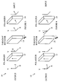
- The manner in which a reversible optical isolator is constructed from a Faraday rotator having a reversible magnetic field may be more easily understood with reference to Figures 1-4 which illustrate the propagation of light through the basic elements of an
optical isolator 10 having a reversible pass direction.Isolator 10 is constructed from two polarization filters shown at 12 and 16 and a Faradayrotator 14. For the purposes of this discussion,polarization filter 12 is assumed to pass light which is polarized in a direction parallel to the y-axis, andpolarization filter 16 passes light whose polarization is at 45° to the y-axis as indicated by the arrow onpolarization filter 16. Light entering the input ofisolator 10 is assumed to have at least some intensity along the y-axis. If the light has a polarization vector that is at an angle to the y-axis, the component of the light having a polarization parallel to the x-axis will be removed bypolarization filter 12; hence, only the light having a polarization vector parallel to the y-axis needs be considered. This light leaves polarization filter 12 and passes through Faradayrotator 14, which rotates the polarization vector through 45° as shown at 15. The direction of polarization now matches the pass direction ofpolarization filter 16, and hence, the light exits through the output port. - The case in which light enters the output port is shown in Figure 2.
Polarization filter 16 selects the component of the polarization that is at 45° to the y-axis. Any light having a polarization at right angles to this direction is removed bypolarization filter 16. Hence, only light having a polarization selected bypolarization filter 16 needs to be considered. The output ofpolarization filter 16 is rotated through 45° by Faradayrotator 14, since the direction of rotation is independent of the direction of travel of light through the rotator. Hence, the light leaving Faradayrotator 14 will now be parallel to the x-axis as shown at 17. This light will be blocked bypolarization filter 12; hence, no light can pass throughisolator 10 in the reverse direction. - Now consider the case in which the magnetic field applied to Faraday
rotator 14 is reversed. The input and output port designations are also reversed. In this case, Faradayrotator 14 will rotate the polarization of the light passing therethrough by -45° independent of the direction of travel of the light relative to the z-axis of the coordinate system shown in the figures. Referring to Figure 3, light entering the input end ofisolator 10 will first pass throughpolarization filter 16 which selects the component of the light at 45° to the x-axis. Any polarization component at 90° to this direction is removed bypolarization filter 16; hence, only the component at 45° needs to be considered. This component is rotated through -45° by Faradayrotator 14; hence, the light leaving Faradayrotator 14 now has a polarization vector that is vertical as shown at 18. This light will pass throughpolarization filter 12 andexits isolator 10. - The case in which light enters the output port is shown in Figure 4. Since only the polarization component of the light parallel to the y-axis will exit
polarization filter 12, only this polarization component needs be considered. The light leavingpolarization filter 12 enters Faradayrotator 14, which rotates the polarization vector through -45°. Hence, the light enteringpolarization filter 16 has a polarization vector that is at -45° to the y-axis. This light is blocked bypolarization filter 16 since it is at right angles to the pass direction of the polarization filter. - From the above discussion, it is apparent that a reversible optical isolator can be constructed from a Faraday rotator in which the magnetic field applied to the material in the Faraday rotator can be reversed in response to signal that is applied to the isolator. Refer now to Figure 5, which is a cross-sectional view of a reversible
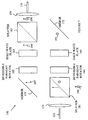
optical isolator 100.Isolator 100 has afirst port 121 which includes anoptical guide 102 and a collimating/imaging lens 103 for collimating the light received onguide 102 or imaging light frompolarization filter 104 back intoguide 102. A similar arrangement is utilized for asecond port 122, which includes anoptical guide 107 and collimating/imaging lens 106. The polarization filter functions discussed above are provided bypolarization filters Polarization filter 104 has a pass orientation that differs from that ofpolarization filter 105 by 45° AFaraday rotator 123 rotates the polarization angle of the light that passes between polarization filters 104 and 105 by ±45° depending on the direction of the magnetic field. The direction of the magnetic field is determined by the current passing throughcoil 110, which generates a magnetic field having a component that is parallel to the direction of travel of the light betweenfilters current source 109, which sets the direction of the current in response to direction control signal. The direction control signal may be electrical or optical. Other embodiments in which the Faraday rotator utilizes a latching material may also be employed in the present invention. In such embodiments a current pulse sets the direction of magnetization. The direction remains the same until another current pulse is applied. Similarly, a permanent magnet together with a device for flipping the direction of the magnet in response to a control signal could also be utilized. - For
optical isolator 100 to function, it is assumed that at least part of the light entering the isolator was aligned with the polarization filter at the input port. The remaining light is lost. Embodiments which do not have this constraint and which pass essentially all of the light may also be constructed from Faraday rotators having magnetic fields that can be switched. Refer now to Figure 6 which is a schematic view of areversible isolator 150 according to the present invention which accepts light on any polarization and passes the light without losses other than those associated with absorption in the optical components.Isolator 150 utilizes two non-reciprocal polarization rotators to accomplish the isolation. Each non-reciprocal polarization rotator consists of a reversible Faraday rotator in series with a half-wave plate. The direction of rotation of the polarization vector provided by the Faraday rotator is the same regardless of the direction of travel of the light therethrough. The half-wave plate, in contrast, provides either a 45° or -45° rotation depending on the direction of travel of the light. As a result, in one direction the polarization vector is rotated through 90°, and in the other, it is rotated through 0°. - Consider the case in which the
reversible Faraday rotators isolator 150 passes light fromport 152 toport 155.Light entering port 152 is collimated bylens 153. Apolarization beam splitter 181 decomposes thepolarization vector 191 of the incoming light into orthogonal components shown at 192 and 194. The polarization beam splitters are constructed from prisms that selectively reflect light of a predetermined polarization while passing light of the orthogonal polarization. The polarization component reflected bysplitter 181 is reflected bymirror 171 intoreversible Faraday rotator 162, which rotates the polarization by 45°. Half-wave plate 163 rotates the polarization vector by another 45° as shown at 195. This polarization passes throughpolarization splitter 182. - The component of the input light that passed through
splitter 181 is shown at 192. This component is likewise rotated through a total of 90° byreversible Faraday rotator 164 and half-wave plate 165. The output of half-wave plate 165 is reflected intosplitter 182 bymirror 172. This polarization is reflected bysplitter 182 intolens 154 where it is combined with the output of half-wave plate 163 discussed above to reconstitute the input light as shown at 196. - Refer now to Figure 7, which illustrates the manner in which light entering
port 155 is blocked from exiting viaport 152 bybeam splitter 181. The combination of half-wave plate 163 andFaraday rotator 162 leaves the polarization vector unchanged for this direction of travel. Hence, the component of the polarization that is passed bysplitter 182 leavesreversible Faraday rotator 162 with the same polarization as shown 197. This component is reflected bymirror 171 intosplitter 181 and passes throughsplitter 181. The component of the input light reflected bysplitter 182 and mirror 172 passes unchanged through half-wave plate 165 andreversible Faraday rotator 164 sinceFaraday rotator 164 reverses the 45° rotation introduced by half-wave plate 165. This component is reflected bysplitter 181 and is recombined withcomponent 197. The reconstituted light then leaves via the bottom ofsplitter 181 as shown at 199, and hence, misseslens 153. - If the magnetic fields in the reversible Faraday rotators are reversed,
light entering port 155 will exitport 152 since the combination of the Faraday rotator's -45° and the half-wave plate -45° will rotate the polarization vectors through 90°. Light with the resultant polarization will be reflected bybeam splitter 181 such that these polarization components are combined and exit vialens 153. Similarly,light entering port 152 will be blocked from leaving viaport 155, because the combination of the -45° rotation provided by the Faraday rotators and the 45° provided by the half-wave plates cancel resulting in the combined light exiting via the top ofsplitter 182, and hence, missinglens 154. - It will be apparent from the above discussion that the combination of the half-wave plates and the polarization beam splitters perform the same polarization filtering function as polarization filters 104 and 105 shown in Figure 5. Accordingly, a reversible isolator may be viewed as a being constructed from a reversible Faraday rotator and two polarization filters, one for setting the polarization of the light incident on the Faraday rotator and one for blocking light of a predetermined polarization leaving the Faraday rotator.
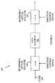
- Refer now to Figure 8, which is a schematic view of an
optical amplifier 200 according to the present invention.Amplifier 200 includes again element 201, which is isolated by reversibleoptical isolators optical guide 204. The direction of propagation of the light throughamplifier 200 is selected by applying a signal to the reversible isolators, which determines the direction of propagation through each of the isolators. It will be apparent that the direction of propagation must be the same for both isolators. The gain element is preferably an Er3+-doped fiber; however other gain elements may be utilized. It should be noted thatoptical amplifier 200 will function with only one of the optical isolators; however, the resulting amplifier may be subject to additional noise. - The above embodiments of the present invention have utilized polarization beam splitters that operate by reflecting light of one polarization while transmitting light of the orthogonal polarization. However, it will be obvious to those skilled in the art from the preceding discussion that other types of beam splitters may be utilized. For example, beam splitters based onwalk-off" crystals in which light components having different polarizations are separated in space by passing the light through a rutile crystal may also be utilized. Accordingly, the term beam splitter as used herein is defined to include any apparatus that separates a beam into two components having orthogonal polarizations.

- Various modifications to the present invention will become apparent to those skilled in the art from the foregoing description and accompanying drawings. Accordingly, the present invention is to be limited solely by the scope of the following claims.
Claims (6)
- A reversible optical isolator[100, 150] comprising: a first polarization filter[104, 181]; a Faraday rotator[123, 162, 164] having a magnetic field direction determined by a control signal received by said Faraday rotator[123, 162, 164]; and a second polarization filter[105, 182].
- The optical isolator[100, 150] of claim 1 wherein said first polarization filter[104, 181] comprises a polarization beam splitter for splitting light incident thereon into two light beams having orthogonal polarizations.
- The optical isolator[100, 150] of claim 2 wherein said second polarization comprises a half-wave plate[165] and a polarization beam splitter[182] for splitting light incident thereon into two light beams having orthogonal polarizations.
- An optical amplifier[200] comprising: an optical guide[204] for receiving light to be amplified; a gain element[201] connected to said optical guide for amplifying light passing therethrough; and a first optical isolator[202] coupled to said gain element for preventing light from propagating in a direction determined by a control signal applied to said first optical isolator[202].
- The optical amplifier[200] of claim 4 wherein said first optical isolator[202] comprises a Faraday rotator having a magnetic field direction determined by said control signal.
- The optical amplifier[200] of claim 4 further comprising a second optical isolator[203] coupled to said gain element for preventing light from propagating in a direction determined by said control signal, said gain element[201] being sandwiched between said first and second optical isolators[202,203].
Applications Claiming Priority (2)
| Application Number | Priority Date | Filing Date | Title |
|---|---|---|---|
| US13868 | 1998-01-27 | ||
| US09/013,868 US6101026A (en) | 1998-01-27 | 1998-01-27 | Reversible amplifier for optical networks |
Publications (1)
| Publication Number | Publication Date |
|---|---|
| EP0932069A1 true EP0932069A1 (en) | 1999-07-28 |
Family
ID=21762212
Family Applications (1)
| Application Number | Title | Priority Date | Filing Date |
|---|---|---|---|
| EP98118664A Withdrawn EP0932069A1 (en) | 1998-01-27 | 1998-10-02 | Reversible optical isolator for optical networks and amplifier |
Country Status (3)
| Country | Link |
|---|---|
| US (1) | US6101026A (en) |
| EP (1) | EP0932069A1 (en) |
| JP (1) | JPH11264959A (en) |
Cited By (6)
| Publication number | Priority date | Publication date | Assignee | Title |
|---|---|---|---|---|
| EP1033604A2 (en) * | 1999-03-03 | 2000-09-06 | Agilent Technologies Inc | Reversible ring coupler for optical networks |
| US6571030B1 (en) | 1999-11-02 | 2003-05-27 | Xros, Inc. | Optical cross-connect switching system |
| US6597826B1 (en) | 1999-11-02 | 2003-07-22 | Xros, Inc. | Optical cross-connect switching system with bridging, test access and redundancy |
| US6650803B1 (en) | 1999-11-02 | 2003-11-18 | Xros, Inc. | Method and apparatus for optical to electrical to optical conversion in an optical cross-connect switch |
| US6792174B1 (en) | 1999-11-02 | 2004-09-14 | Nortel Networks Limited | Method and apparatus for signaling between an optical cross-connect switch and attached network equipment |
| CN101900892A (en) * | 2010-06-23 | 2010-12-01 | 福建福晶科技股份有限公司 | Wavelength tunable opto-isolator |
Families Citing this family (11)
| Publication number | Priority date | Publication date | Assignee | Title |
|---|---|---|---|---|
| US6535324B1 (en) * | 2000-05-23 | 2003-03-18 | Novera Optics, Inc. | Bi-directional wavelength-selective optical data apparatus |
| US6459528B1 (en) * | 2000-05-23 | 2002-10-01 | Avanex Corporation | Optical passive components and bi-directional amplifier |
| US6839169B2 (en) * | 2002-06-17 | 2005-01-04 | Agilent Technologies, Inc. | Optical apparatus and method for selectively transmitting optical signals |
| US7128687B2 (en) * | 2004-03-19 | 2006-10-31 | Ford Global Technologies, Llc | Electromechanically actuated valve control for an internal combustion engine |
| TWI360967B (en) * | 2008-10-28 | 2012-03-21 | Ind Tech Res Inst | Reconfigurable optical amplifier, reversible optic |
| US11002911B2 (en) | 2016-07-22 | 2021-05-11 | Skorpios Technologies, Inc. | Monolithically-integrated, polarization-independent circulator |
| US9453965B2 (en) * | 2011-06-08 | 2016-09-27 | Skorpios Technologies, Inc. | Systems and methods for photonic polarization rotators |
| US9337933B2 (en) | 2012-10-19 | 2016-05-10 | Skorpios Technologies, Inc. | Integrated optical network unit |
| EP2880764B1 (en) | 2012-08-06 | 2019-10-23 | Skorpios Technologies, Inc. | Method and system for the monolithic integration of circuits for monitoring and control of rf signals |
| CN106019617B (en) * | 2016-07-28 | 2018-11-06 | 中国工程物理研究院应用电子学研究所 | A kind of optically isolated beam merging apparatus |
| CN113534351B (en) * | 2021-09-17 | 2022-02-11 | 北京工业大学 | Column vector optical fiber isolator and optical equipment |
Citations (4)
| Publication number | Priority date | Publication date | Assignee | Title |
|---|---|---|---|---|
| US4650289A (en) * | 1979-02-21 | 1987-03-17 | Fujitsu Limited | Optical circulator |
| JPH01274111A (en) * | 1988-04-27 | 1989-11-01 | Hitachi Electron Eng Co Ltd | Optical isolator with shutter function |
| JPH03125125A (en) * | 1989-10-09 | 1991-05-28 | Nippon Telegr & Teleph Corp <Ntt> | Optical amplification part |
| JPH04264227A (en) * | 1991-02-19 | 1992-09-21 | Nippon Telegr & Teleph Corp <Ntt> | Optical fiber transmission line and detection of fault thereof |
Family Cites Families (2)
| Publication number | Priority date | Publication date | Assignee | Title |
|---|---|---|---|---|
| WO1994015243A1 (en) * | 1992-12-22 | 1994-07-07 | Telstra Corporation Limited | An optical isolator |
| US5815308A (en) * | 1996-05-20 | 1998-09-29 | Northern Telecom Limited | Bidirectional optical amplifier |
-
1998
- 1998-01-27 US US09/013,868 patent/US6101026A/en not_active Expired - Fee Related
- 1998-10-02 EP EP98118664A patent/EP0932069A1/en not_active Withdrawn
-
1999
- 1999-01-25 JP JP11015540A patent/JPH11264959A/en active Pending
Patent Citations (4)
| Publication number | Priority date | Publication date | Assignee | Title |
|---|---|---|---|---|
| US4650289A (en) * | 1979-02-21 | 1987-03-17 | Fujitsu Limited | Optical circulator |
| JPH01274111A (en) * | 1988-04-27 | 1989-11-01 | Hitachi Electron Eng Co Ltd | Optical isolator with shutter function |
| JPH03125125A (en) * | 1989-10-09 | 1991-05-28 | Nippon Telegr & Teleph Corp <Ntt> | Optical amplification part |
| JPH04264227A (en) * | 1991-02-19 | 1992-09-21 | Nippon Telegr & Teleph Corp <Ntt> | Optical fiber transmission line and detection of fault thereof |
Non-Patent Citations (3)
| Title |
|---|
| DATABASE WPI Section Ch Week 9127, Derwent World Patents Index; Class L03, AN 91-198696, XP002102592 * |
| PATENT ABSTRACTS OF JAPAN vol. 014, no. 044 (P - 0996) 26 January 1990 (1990-01-26) * |
| PATENT ABSTRACTS OF JAPAN vol. 017, no. 051 (P - 1479) 2 February 1993 (1993-02-02) * |
Cited By (8)
| Publication number | Priority date | Publication date | Assignee | Title |
|---|---|---|---|---|
| EP1033604A2 (en) * | 1999-03-03 | 2000-09-06 | Agilent Technologies Inc | Reversible ring coupler for optical networks |
| EP1033604A3 (en) * | 1999-03-03 | 2002-04-24 | Agilent Technologies, Inc. (a Delaware corporation) | Reversible ring coupler for optical networks |
| US6571030B1 (en) | 1999-11-02 | 2003-05-27 | Xros, Inc. | Optical cross-connect switching system |
| US6597826B1 (en) | 1999-11-02 | 2003-07-22 | Xros, Inc. | Optical cross-connect switching system with bridging, test access and redundancy |
| US6650803B1 (en) | 1999-11-02 | 2003-11-18 | Xros, Inc. | Method and apparatus for optical to electrical to optical conversion in an optical cross-connect switch |
| US6792174B1 (en) | 1999-11-02 | 2004-09-14 | Nortel Networks Limited | Method and apparatus for signaling between an optical cross-connect switch and attached network equipment |
| US6813407B2 (en) | 1999-11-02 | 2004-11-02 | Nortel Networks Limited | Method and apparatus for bridging optical signals in an optical network |
| CN101900892A (en) * | 2010-06-23 | 2010-12-01 | 福建福晶科技股份有限公司 | Wavelength tunable opto-isolator |
Also Published As
| Publication number | Publication date |
|---|---|
| JPH11264959A (en) | 1999-09-28 |
| US6101026A (en) | 2000-08-08 |
Similar Documents
| Publication | Publication Date | Title |
|---|---|---|
| US6101026A (en) | Reversible amplifier for optical networks | |
| US5212586A (en) | Optical circulator having a simplified construction | |
| JP2757093B2 (en) | Non-polarization dispersion type optical isolator | |
| US6597503B2 (en) | Reflection-type optical circulator utilizing a lens and birefringent plates | |
| EP0252509A2 (en) | An Optical isolator device having two cascaded isolator elements with different light beam rotation angels | |
| US6088491A (en) | Optical circulator | |
| US6396629B1 (en) | Multi-functional optical device utilizing multiple birefringent plates and a non-linear interferometer | |
| US6587266B2 (en) | Bi-directional isolator | |
| JPH09189885A (en) | Optical device | |
| US6493141B2 (en) | Multi-functional optical device utilizing multiple polarization beam splitters and non-linear interferometers | |
| US6430323B1 (en) | Polarization maintaining optical isolators | |
| US6631238B2 (en) | Variable optical attenuator | |
| US6360034B1 (en) | Reflection based nonmoving part optical switch | |
| US6885821B2 (en) | Full-duplex optical add/drop communications system utilizing central light sources | |
| US6188810B1 (en) | Reversible ring coupler for optical networks | |
| US7024073B2 (en) | Reflective variable light attenuator | |
| US6760158B1 (en) | Multi-functional optical device utilizing multiple polarization beam splitters and non-linear interferometers | |
| US6297901B1 (en) | Optical attenuating isolator | |
| US6091866A (en) | Optical isolator | |
| EP0634844A1 (en) | Non-reciprocal optical diplexer | |
| US6762879B1 (en) | Method and system for providing an optical circulator | |
| GB2143337A (en) | Optical isolator | |
| EP0364968B1 (en) | Optical isolator | |
| JP3936451B2 (en) | Optical attenuator module | |
| JPH11311754A (en) | Optical circulator |
Legal Events
| Date | Code | Title | Description |
|---|---|---|---|
| PUAI | Public reference made under article 153(3) epc to a published international application that has entered the european phase |
Free format text: ORIGINAL CODE: 0009012 |
|
| AK | Designated contracting states |
Kind code of ref document: A1 Designated state(s): DE FR GB |
|
| AX | Request for extension of the european patent |
Free format text: AL;LT;LV;MK;RO;SI |
|
| 17P | Request for examination filed |
Effective date: 19990712 |
|
| AKX | Designation fees paid |
Free format text: DE FR GB |
|
| RAP1 | Party data changed (applicant data changed or rights of an application transferred) |
Owner name: AGILENT TECHNOLOGIES, INC. |
|
| RAP1 | Party data changed (applicant data changed or rights of an application transferred) |
Owner name: AGILENT TECHNOLOGIES INC. |
|
| RAP1 | Party data changed (applicant data changed or rights of an application transferred) |
Owner name: AGILENT TECHNOLOGIES INC. A DELAWARE CORPORATION |
|
| RAP1 | Party data changed (applicant data changed or rights of an application transferred) |
Owner name: AGILENT TECHNOLOGIES, INC. (A DELAWARE CORPORATION |
|
| 17Q | First examination report despatched |
Effective date: 20040225 |
|
| GRAP | Despatch of communication of intention to grant a patent |
Free format text: ORIGINAL CODE: EPIDOSNIGR1 |
|
| RTI1 | Title (correction) |
Free format text: REVERSIBLE TELECOMMUNICATION RING NETWORK |
|
| RTI1 | Title (correction) |
Free format text: REVERSIBLE TELECOMMUNICATION RING NETWORK |
|
| STAA | Information on the status of an ep patent application or granted ep patent |
Free format text: STATUS: THE APPLICATION HAS BEEN WITHDRAWN |
|
| 18W | Application withdrawn |
Effective date: 20050113 |