EP0935058A2 - Radiators and soundproofing engine enclosure designs - Google Patents
Radiators and soundproofing engine enclosure designs Download PDFInfo
- Publication number
- EP0935058A2 EP0935058A2 EP99300840A EP99300840A EP0935058A2 EP 0935058 A2 EP0935058 A2 EP 0935058A2 EP 99300840 A EP99300840 A EP 99300840A EP 99300840 A EP99300840 A EP 99300840A EP 0935058 A2 EP0935058 A2 EP 0935058A2
- Authority
- EP
- European Patent Office
- Prior art keywords
- engine
- soundproofing
- enclosure
- air
- porous
- Prior art date
- Legal status (The legal status is an assumption and is not a legal conclusion. Google has not performed a legal analysis and makes no representation as to the accuracy of the status listed.)
- Withdrawn
Links
Images


Classifications
-
- F—MECHANICAL ENGINEERING; LIGHTING; HEATING; WEAPONS; BLASTING
- F28—HEAT EXCHANGE IN GENERAL
- F28D—HEAT-EXCHANGE APPARATUS, NOT PROVIDED FOR IN ANOTHER SUBCLASS, IN WHICH THE HEAT-EXCHANGE MEDIA DO NOT COME INTO DIRECT CONTACT
- F28D7/00—Heat-exchange apparatus having stationary tubular conduit assemblies for both heat-exchange media, the media being in contact with different sides of a conduit wall
- F28D7/10—Heat-exchange apparatus having stationary tubular conduit assemblies for both heat-exchange media, the media being in contact with different sides of a conduit wall the conduits being arranged one within the other, e.g. concentrically
- F28D7/106—Heat-exchange apparatus having stationary tubular conduit assemblies for both heat-exchange media, the media being in contact with different sides of a conduit wall the conduits being arranged one within the other, e.g. concentrically consisting of two coaxial conduits or modules of two coaxial conduits
-
- F—MECHANICAL ENGINEERING; LIGHTING; HEATING; WEAPONS; BLASTING
- F01—MACHINES OR ENGINES IN GENERAL; ENGINE PLANTS IN GENERAL; STEAM ENGINES
- F01P—COOLING OF MACHINES OR ENGINES IN GENERAL; COOLING OF INTERNAL-COMBUSTION ENGINES
- F01P3/00—Liquid cooling
- F01P3/18—Arrangements or mounting of liquid-to-air heat-exchangers
-
- F—MECHANICAL ENGINEERING; LIGHTING; HEATING; WEAPONS; BLASTING
- F02—COMBUSTION ENGINES; HOT-GAS OR COMBUSTION-PRODUCT ENGINE PLANTS
- F02B—INTERNAL-COMBUSTION PISTON ENGINES; COMBUSTION ENGINES IN GENERAL
- F02B77/00—Component parts, details or accessories, not otherwise provided for
- F02B77/11—Thermal or acoustic insulation
- F02B77/13—Acoustic insulation
-
- F—MECHANICAL ENGINEERING; LIGHTING; HEATING; WEAPONS; BLASTING
- F28—HEAT EXCHANGE IN GENERAL
- F28F—DETAILS OF HEAT-EXCHANGE AND HEAT-TRANSFER APPARATUS, OF GENERAL APPLICATION
- F28F13/00—Arrangements for modifying heat-transfer, e.g. increasing, decreasing
- F28F13/003—Arrangements for modifying heat-transfer, e.g. increasing, decreasing by using permeable mass, perforated or porous materials
Definitions
- the present invention relates to a radiator composed of porous metallic substance high in thermal conductivity and also relates to a soundproofing system for a heat engine shielded acoustically with a soundproofing enclosure of a sound isolating member containing therein vacuum cavities.
- a cogeneration system of a heat engine/electric power generator set in general utilizes the combustion of fuel such as kerosene or the like.
- fuel such as kerosene or the like.
- Most cogeneration systems have been customarily stationed in urban districts or highly-populated areas and become a major problem of environmental pollution due to their exhaust gas, noise, vibration or the like.
- a heat accumulator with an engine has been proposed in Japanese Utility Model Laid-Open No. 128150/1987, in which the engine is submerged in a heat-transfer medium such as water or the like filled in a heat accumulating reservoir.
- a heat-emitting machinery with sound isolating means in which a housing contains the machinery emitting noise and heat in operation.
- a soundproofed engine of water cooled type shown in Japanese Utility Model Laid-Open No. 166248/1989, has been well known wherein the engine with a muffler is installed in a soundproofing enclosure filled with liquid in which are in combination submerged the engine and muffler.
- turbo-chargers such as turbo-chargers. It is well known that compressing air by the supercharger causes temperature rise in the intake air or in the heat engine owing to adiabatic compression. The temperature rise in the intake air in the engine decreases the volumetric efficiency and increases the temperature of air-fuel mixture, which results in increasing the tendency to combustion knock. To cope with the phenomenon, the engines are in general provided with the radiators for cooling down the cooling liquid by dissipating the heat picked up in the heat engine.
- radiators have the fans that are driven by the crankshafts through the endless belts drivingly connecting the fans with the pleys secured on the crankshafts.
- the hot liquid from the heat engine is circulated through many small pipes equipped with fins, while cooled by a current of air, which is created by the action of the fans as well as the motion of the vehicle and forced to flow rapidly through the spaces between fins to thereby dissipate the heat in the cooling liquid.
- the conventional radiator as described above is formed in quadrangle regardless of the fan being of circular configuration. As a result, the radiator is provided with the heat exchanger having the surface area that is fixed in size with no regard to the temperature of the cooling liquid, so that the cooling effect is reduced extremely.
- the cooling liquid flowing through the radiator core may be heat exchanged with atmospheric airflow created by the fan or the motion of the vehicle.
- the radiator is arranged ahead of the engine.
- openings must be provided towards the transmission behind the engine for the egress of the airflow.
- the radiator core is usually formed with fins on the exterior of the tubing and pipes through which may flow the cooling liquid. In this way, the heat-transfer surface extension inevitably results in making the radiator larger in size.
- the radiator In the radiator to cool the intake air for the heat engine, it should be high in efficiency of heat exchanging with gaseous substance or the intake air to be cooled, nevertheless compact in size as well as resistant to pressure and vibration.
- a porous-metal body may be produced of the metallic substance such as aluminum or aluminum alloys, which is high in thermal conductivity.
- Thermal conductivity of aluminum is 220W/m ⁇ K
- Si 3 N 4 is 20W/m ⁇ K
- SiC is 90W/m ⁇ K. It will be apparent that aluminum is higher in thermal conductivity comparison with Si 3 N 4 and SiC. Accordingly, it may be proposed to produce the radiator with making use of aluminum high in thermal conductivity.
- gases such as air are low in thermal conductivity and, therefore, it is necessary for uniform heat transmission to extend the area of heat-transfer surface in contact with the gases.
- Hybrid car pollution will arise from noise generated from the engines and motors as well as exhaust gases emitted out of the engines.
- Diesel engines superior in thermal efficiency might accomplish reduction of exhaust gases, whereas the noise pollution due to diesel engines might become a major problem.
- the hybrid cars have no power transmission system, but is provided with a motor that is easily recognized as a source of noise pollution. To diminish hybrid bar noise pollution, it is preferred to provide soundproofing motor enclosure designs.
- the radiator On most engines for the vehicles, the radiator is usually arranged ahead of the engine to utilize the fresh air movement caused from the motion of the vehicle.
- This cooling system requires to be opened towards the transmission behind the engine for the egress of the current of air. It will be thus understood that the radiator is an obstacle to the engine enclosure designs. That is, the decibel level of the engine noise cannot be reduced by an enclosure shrouding the engine block, which is opened to the atmosphere for entrance and egress of the current of cooling air to the radiator. Shielding the exhaust manifolds with the soundproofing shell causes other problem of overheating in the shells.
- Noise and vibration occurring in the massive stationary engines have become a major problem in a structure to which is installed the engine of large size.
- the vibration of noisy machinery, or heat engine is transmitted through the whole structure and causes secondary noise at places where the vibration is matched in frequency to that of the structure. This phenomenon is making it much more difficulty to suppress the vibration and noise.
- the noise emitted from the engines involves two noise components, one of which is air-borne noise of sound radiation and the other of which is noise owing to vibratory motion of the engine itself, transmitted as air-borne vibration to the structure where resonance occurs when the noise frequency approaches the natural frequency of the structure.
- the resonance results in secondary noise radiated and spread from the interior of the structure over the community.
- an electric power generator combined with a heat-insulating engine has a great generating capacity of, for example, about 100KW that may be utilized for various appliances. It may be, for instance, proposed to utilize the electric power of the engine/electric power generator set for actuating an electric fan to blow a current of cooling air through a radiator that is mounted at any other suitable location on the vehicle than ahead the engine. In such case as described just above, the radiator has to be designed so as to make effective use of the cooling airflow charged by the electric fan.
- Sound insulating panels have been conventionally employed for isolating noise occurring in the engines.
- For maximum effective isolation of noise source it has been well known to provide partitions of heavy material, or partitions consisting of, in combination, solids and gases. Where the engine is confined within a narrow closed space, there is a fear that sound wave, or the origin of noise, is reflected on the surfaces of the partitions and amplified by resonance or the like, resulting in causing complicated vibrations.
- a laminated composite structure may be preferred that consists of a laminated composite core through which might penetrate the sound wave, and a skin of heavy material, for example, lead or the like, enclosing therewith the composite core, and further the composite core being composed of a first solid, a gas and a second solid which are laid one on top of another in alternate layer.
- recommendable for effective sound isolation is a double panel structure of hollow-core type in which a spacing between the parallel, spaced heavy panels is decompressed or in vacuum so as to discontinue the transmission of the sound wave.
- the soundproofing structure for engines has an electric power supply system mounted on a carrier for the purpose of suppressing noise and vibration generated by the engine.
- the wheeled carrier having mounted thereon a heat engine/electric power generator set is installed on a base laid in an accommodation space at the installation site.
- the accommodation space is defined by laminated composite walls, each of which walls is comprised of a metallic housing of hollow-core type, rubber-made coating layers attached to the inside surfaces of the housing, and a corrugated supporting member inserted within the housing.
- the hollow-core housings are each kept in vacuum.
- the multi-layered wall is composed of a hollow-core structural member of synthetic resin or metal with which is encapsulated a porous plate of porous or fibrous material having a vacuum layer therein, a foamed structural member of foamed resin surrounding around the hollow-core structural member, a saw-toothed sheet consisting of heat resisting glass wool and a supporting member, and a square-corrugated metal sheet, the saw-toothed sheet being arranged inside the enclosure unit while the square-corrugated metal sheet being arranged outside the enclosure unit.
- An aim of the present invention is to provide a radiator for transferring heat from a hot liquid to a cold air, which may be installed at any other required location than ahead the heat engine, and more particularly to provide a improved radiator in which passages to flow a current of air therethrough are provided by porous-metal bodies of metals such as aluminum or aluminum alloys or the like high in thermal conductivity, thereby exposing more metal surface to the current of air to increase the coefficient of overall heat transmission, and fans are incorporated in the radiator.
- the porous-metal bodies may be fabricated by making use of prior art such as salt cores or the like.
- Another aim of the present invention is to provide a soundproofing engine enclosure design wherein a sound insulating enclosure is made form a laminated composite panel easy to be formed by press work while easy to be kept at its interior in the decompressed or vacuum condition, and wherein the radiator is designed so as to have no necessity of utilizing the fresh air movement caused from the motion of the vehicle and therefore may be installed at any other required location than ahead the heat engine for most effective sound isolation by the soundproofing enclosure of noise occurring in vehicle engines, cogeneration system, electric power plant engines, water pumps, motor generators or the like, and further wherein the soundproofing enclosure shields the heat engine and its associated equipment of noise sources to thereby prevent radiation of noise.
- a further aim of the present invention is to provide, in a radiator for transferring heat from a cooling liquid to air for cooling down a cooling liquid for an engine, the improvement comprising an inner cylinder made of metal high in thermal conductivity and providing a cylindrical air tunnel for flowing the air therethrough, an outer cylinder arranged around the inner cylinder so as to provide therebetween an annular passage for flowing the cooling liquid, porous-metal bodies arranged in the inner cylinder and made of a metal high in thermal conductivity so as to have interconnecting voids permitting the flow of the air therein, and fans arranged in the inner cylinder so as to made the air flow in the porous-metal bodies.
- the porous-metal bodies each are made of aluminum or aluminum alloys, and have a porous structure formed by molten metal that is poured in a mold of foamed urethane resin having therein foams charged with salt cores.
- fins to radiate heat formed around both the inner and outer cylinders are also made of any one of aluminum and aluminum alloys.
- the porous-metal bodies for the radiator of the present invention have the metal-continuity without thermal interruption as well as the porous structure involving interconnecting voids therein.
- This porous-metal bodies of aluminum or aluminum alloys may be produced by a molten metal of aluminum or aluminum alloys that is poured in a mold charged with salt cores, which have a melting point of 700 °C higher than aluminum of a melting point of 600 °C .
- the porous-metal bodies are different in porosity with each other and stacked in the inner cylinder in series along a direction of a current of air.
- any porous-metal bodies relative rich in porosity are upstream the current of air while other porous-metal bodies relative less in porosity are downstream the current of air.
- the porous-metal bodies may be selected in their porosity or density so as to achieve the most cooling efficiency at the areas where the temperature difference of the liquid with the air is larger, while so as to adjust the air resistance that might increase when the porous-metal bodies rich in density alone are used.
- the pitches of the helical fin in the annular passage for the cooling liquid are designed so as to achieve the most cooling efficiency at the areas where the temperature difference of the liquid with the air is larger, while so as to adjust the liquid-flow resistance that might increase when the helical fin shorter in pitch alone are used.
- the porous-metal bodies in the inner cylind are of honeycomb structure.
- walls of cells in honeycomb appearance are selected such that the thickness of the walls in the core-side honeycomb is relatively thinner compared with the walls in the periphery-side honeycomb.
- the fans are arranged upstream and downstream with respect to the porous-metal bodies in the inner cylinder, one to each side.
- the fin in the annular passage within the outer cylinder extends helically, continuously from an inflow port to an outflow port for the cooling liquid so as to make the cooling liquid flow in a direction opposite to that of the current of air in the air tunnel.
- the fin is of a variable-pitch type in which the pitches of helical at the upstream portion of the annular passage are larger compared with the downstream portion. This helical fin may help ensure the smooth flow of the liquid, which is guided along the fin in the annular passage.
- the helical fin may be simply generated by helically cutting the outer peripheral surface of the inner cylinder.
- the fans are driven by the motor that may be adjusted by means of the commands of a controller in accordance with the operational conditions of the engine.
- the generator encapsulated together with the heat engine in the soundproofing enclosure may provide the electric power that is sufficient to drive the fans in the radiator remote from the heat engine.
- the fans may be, thus, actuated by making use of the electric power originating in the generator to thereby forcing the cooling air into the radiator. Further the fans may be controlled in response to the operational conditions of the heat engine so as to help achieve the most cooling efficiency.
- the outer cylinder is provided around the periphery thereof with fins for air cooling, and a silencer is mounted at the egress opening of the air tunnel in the inner cylinder.
- the inner cylinder for the air tunnel is formed in right circular configuration in cross section in coincidence with the peripheral airflow configuration of the fans and the air tunnel accommodates therein porous-metal bodies that have interconnecting voids for permitting the current of air to flow through the air tunnel.
- porous-metal bodies that have interconnecting voids for permitting the current of air to flow through the air tunnel.
- the porous-metal bodies may function as the metal bodies superior in thermal conductivity, which are great in coefficient of overall heat transmission with resulting in increasing the heat exchanging efficiency of the radiator.
- the area of heat-transfer surface in contact with intake air, or the air-side heat-transfer surface should be more than or equal to about twenty times as large as that of the heat-transfer surface in contact with the cooling liquid, or the water-side heat-transfer surface.
- the gas-flow paths formed of porous-metal bodies may, easily satisfy this requisition, or the air-side heat-transfer surface of twenty times as large as that of the water-side heat-transfer.
- Another aim of the present invention is to provide a soundproofing engine enclosure designs wherein a soundproofing enclosure is mounted to an engine body having combustion chambers for constituting the engine, an engine mount for fixing the engine body to a bed frame, and a transmission casing for a transmission connected to a power take-off shaft through a clutch; wherein the soundproofing enclosure shields at least the engine body, a water pump attached to the engine body for circulating the cooling liquid to cool down the engine body, a fuel injection pump mounted to the engine body for forcing fuel into the engine, and a motor generator connected to the power take-off shaft between the clutch and the engine, and further wherein the radiator is arranged outside the enclosure for cooling down the cooling liquid that is made to circulate through the engine by the action of the water pump.
- the radiator arranged outside the soundproofing enclosure is preferably of the structure described hereinbefore.
- the engine and the radiator are communicated with each other through cooling liquid hoses that bore through the soundproofing enclosure.
- the soundproofing enclosure shields through elastic bodies of sound insulating rubber at least all of the engine mount, the cooling liquid hoses, intake pipes for feeding intake air to the engine, exhaust pipes for expelling exhaust gases from the engine, the transmission and the fuel pipes for supplying fuel to the engine.
- both the exhaust manifolds for expelling the exhaust gases out of the combustion chambers and the exhaust pipes connected with the exhaust manifolds are formed in heat insulating structure so as to suppress radiation of heat in the soundproofing enclosure.
- the temperature in the soundproofing enclosure may be kept from exceeding limits that might otherwise cause deterioration of the devices confined in the enclosure.
- the motor generator has two functions, one of which is to convert braking force into electric energy and another of which is to serve as a starter motor.
- the soundproofing enclosure is formed from a soundproofing panel of hollow-core type that is kept in a substantially vacuum condition.
- the soundproofing enclosure especially, comprises a laminated composite structure that is composed of metal sheets confronting each other with a spacing therebetween, and an intermediate layer keeping the metal sheets at the design spacing relation and connected at its opposing surfaces to the metal sheets by fusion-seizure of hard rubber, the laminated composite structure being able to be formed in a design configuration by press molding, the spacing between the confronting metal sheets being hermetically sealed at the peripheral edges of the metal sheets by means of sealing members, and interconnecting voids in the intermediate layer being decomposed to the substantially vacuum condition. That is, the sound insulating panel for the soundproofing enclosure may be produced from the laminated composite structure that is composed of a pair of the metal sheets and the intermediate layer interposed between the metal sheets.
- the laminated composite structure is subjected to the press forming and the cutting by a cutter so as to be finished into the design configuration, then the sealing member is applied over the confronting peripheral edges of the metal sheets so as to cover the spacing between the metal sheets and to seal hermetically the intermediate layer between the metal sheets, and the voids in the intermediate layer confined between the metal sheets are decompressed to the substantially vacuum atmosphere.
- the soundproofing enclosure is provided on the inside thereof with a liner of sponge rubber.
- the fans are arranged upstream and downstream with respect to the porous-metal bodies in the inner cylinder, one to each side, and driven by the motor that is adjusted in speed by means of the commands of the controller in accordance with the cooling liquid temperatures and the operational conditions of the engine.
- the motor generator encapsulated together with the heat engine in the soundproofing enclosure may generate the electric power that is sufficient to drive the fans in the radiator remote from the heat engine.
- the fans may be, thus, actuated by making use of the electric power originating in the motor generator to thereby forcing the cooling air into the radiator. Further the fans may be controlled in response to the cooling liquid temperatures and the operational conditions of the heat engine so as to help achieve the most cooling efficiency.
- the soundproofing enclosure may shield the heat engine with its associated devices, exclusive of the radiator, the enclosure may be made simple in its configuration while the engine may be encapsulated with ease. Moreover the soundproofing enclosure may acoustically confine therein the noise generating from the heat engine and generator to help ensure the quietness of the vehicle or the like.
- the crankshaft is disconnected when idling by the disengagement of the clutches so as to cut off the noise transmitting route, so that no output and noise from the engine are allowed to reach specific applications. Consequently, the only vibration-transmitting path remains in the transmission case so that about 90% of noise may be isolated from the environment.
- the soundproofing engine enclosure design of the present invention may isolate the noise due to the heat engine in the soundproofing enclosure to thereby prevent the noise from spreading over the community. Because no power output from the engine when idling, especially, is applied to the transmission, the soundproofing enclosure may ensure the sound isolation for the noise originating in the motor generator that generates the electric power for operating the working applications, resulting in the provision of very quiet operation. Moreover in the heat engine design shielded with the soundproofing enclosure of the present invention, both the exhaust manifolds and the exhaust pipes are covered with the heat insulating structure so as to suppress radiation of heat from the exhaust gases into the soundproofing enclosure. As a result, the temperature in the soundproofing enclosure may be kept from exceeding limits that might otherwise cause deterioration of the devices equipped with the heat engine. The heat engine designis kept in a substantially vacuum condition.
- the soundproofing enclosure especially, comprises a laminated composite structure that is composed of metal sheets confronting each other with a spacing need of a separate engine that might otherwise be provided on the vehicle for generating the electric power.
- the radiator constructed as described above may provide the remarkably extended heat transfer surface that is exposed to the current of air, thereby attaining the increase of high heat exchanging efficiency with the cooling liquid.
- the radiator also makes possible larger heat transfer surface area than is provided in the prior radiators equipped with fins and, therefore, may be made compact in structure.
- the radiator of the present invention is superior in heat exchanging efficiency as well as may be miniaturized and further uses the current of air forced by the action of the fans.
- this radiator may be installed wherever needed with respect to the engine by simply connecting the annular passage thereof with the hot liquid outlet and cool liquid inlet of the engine through the hoses or the like. This makes it possible to free the engine design from the critical limitations regarding the radiator while shroud the heat engine and its associated devices, exclusive of the radiator, with the soundproofing enclosure.
- the presenting member is applied over the confronting peripheral edges of the metal sheets so as to cover the spacing between the metal sheetse voids therein.
- the rubber-made sponge plate for the intermediate layer is preferably mixed with any one of carbon and ceramics for enhancing the strength and hardness.
- the intermediate layer may be made from coarse wire netting, each wire of which is covered with a hard rubber coating.
- press molding of the laminated composite structure may easily form the soundproofing enclosure.
- the laminated composite structure composed of metal sheets and the intermediate layer of hard rubber following application of an adhesive agent on the metal sheets and/or the intermediate layer, they are laminated one on the another in such a manner that the intermediate layer, or the sponge plate of hard rubber, is sandwiched between the confronting metal sheets.
- Subsequently heating treatment is applied to the laminated structure that is in turn integrated into the laminated composite structure in which the layers are fusion-seized together with each other with the voids being contained therein.
- the composite structure is then subjected to the press forming and the cutting by a cutter so as to be finished into the design configuration with an air vent.
- the voids confined between the metal sheets are decompressed to the substantially vacuum condition through the air vent that is in turn plugged.
- the metal sheets may happen occasionally, locally to make direct contact with each other on the press forming of the laminated composite structure, the hard rubber with vacuum voids are substantially interposed between the metal sheets to keep the sufficient sound isolation. It will be noted that the vibration of noise may be absorbed by the hard rubber while the transmission of noise itself may be discontinue at the vacuum or decompressed layer between the metal sheets.
- the soundproofing composite structure for providing the soundproofing enclosure component in which the discontinuities of noise may be obtained effectively at the spacing between the confronting metal sheets kept in the decompressed or vacuum condition.
- the intermediate layer interposed between the metal sheets has the function of keeping the decompressed or vacuum spacing between the metal sheets even when deformed by press molding. Elastic hard rubber of the intermediate layer may impede the transmission of vibration.
- the laminated composite structure of the metal sheets and the intermediate layer may be formed by pressing in the design configurations for the engine enclosure. Further, the intermediate layer contains the interconnecting voids that may be simply decompressed.
- the soundproofing enclosure for heat engines may be applied to, for example, a heat engines 31 of a diesel cycle engine or the like utilizes the combustion of fuel such as kerosene, heavy oil, gaseous fuel or the like.
- the heat engine 31 may be adapted for stationary cogeneration systems using steam for both power generation and heating, vehicle engines, power generation engines and the like.
- the heat engine 31 is of the type, which operates on the four-stroke cycle wherein the phases of intake, compression, combustion, expansion, and exhaust occur sequentially.
- the heat engine 31 has, for example, a cylinder block, a cylinder head fixed to the cylinder block, cylinders formed by cylinder liners fitted in cylinder bore in the cylinder block, and pistons making reciprocation movement in the cylinders.
- the exhaust gas generated in the cylinders of the engine 31 is discharged through exhaust manifolds 49 and exhaust pipes 32.
- the exhaust pipes 32 communicated with the exhaust manifolds 49 may be provided therein with means for recovery of energy from the exhaust gases, for example, turbo-chargers or power generation gas turbines (not shown).
- the heat engine 31 also has a power take-off shaft 33 drivingly connected to a motor generator 34 that is to generate electric energy.
- the motor generator 34 has two functions one of which is to convert braking force into electric energy and another of which is to serve as a starter motor.
- the soundproofing enclosure 35 of the present invention is fundamentally composed of a hollow-core wall structure within which is kept in substantially vacuum so as to discontinue sound transmission through the wall.
- the wall structure is formed in a laminated composite wall in which is arranged a sound-absorbing composite member of a combination of fibrous material and elastic material, which has both sound-absorbing effect and vacuum-preserving effect.
- the enclosure 35 of the present invention is made from the hollow-core soundproofing structure having a cavity therein decompressed to the substantial vacuum.
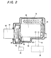
- the soundproofed engine design of this embodiment is comprised of an engine body 36 having combustion chambers for constituting the heat engine 31, an engine mount 38 for fixing the engine body 36 to a bed frame 37, a transmission 40 connected to the power take-off shaft 33 through a clutch 39, the soundproofing enclosure 35 attached to both the frame 37 and a transmission case 41 of the transmission 40 so as to shield at least the engine body 36 and the engine mount 38, and a radiator 30 arranged outside the enclosure 35 for cooling down a cooling liquid circulating through the heat engine 31.
- the soundproofed engine design of this embodiment further includes a water pump 42 mounted to the engine body 36 to circulate the liquid for cooling down the heat engine 31, a fuel injection pump 43 mounted to the engine body 36 for forcing fuel into the heat engine 31, and a motor generator 34 connected to the power take-off shaft 33 through a crankshaft gearing 47 (not shown in FIG. 2) of a crankshaft.
- the soundproofing enclosure 35 is formed so as to shield all of the water pump 42, motor generator 30 and fuel injection pump 43. Cool-liquid hoses 44, 45 bore through the soundproofing enclosure 35 at design locations for communicating between the heat engine 31 and the radiator 30 as well as between the radiator 30 and water pump 42, respectively.
- the soundproofing enclosure 35 is opened at the areas through which extend the engine mount 38, cool liquid hoses 44, 45, intake pipes 46 for charging the intake air into the combustion chambers of the heat engine 31, through intake manifolds 50, the exhaust pipes 32 for discharging exhaust gases out of the engine 31, the transmission 41 and fuel pipes (not shown) for supplying fuel to the heat engine 31. Packed around the boundaries of openings in the enclosure 35 are elastic members 48 of sound isolating rubber.
- Both the exhaust manifolds 49 and the exhaust pipes 32 connected with the exhaust manifolds 49 are formed in heat insulating structure so as to suppress radiation of heat in the soundproofing enclosure 35.
- composite tubing may be, for example, used wherein walls of heat resisting ceramics or the like or walls for forming ports are arranged inside the tubing and shrouded with heat insulating member of ceramic fibers or the like.
- the temperature in the soundproofing enclosure is kept from exceeding limits that might otherwise cause deterioration of equipment such as the water pump 42, fuel injection pump 43, motor generator 34 and the like.
- FIGS. from 3 to 5 illustrating a preferred embodiment of the radiator 30 according to the present invention.
- the radiator 30 is to cool down hot liquid W from the heat engine 31 with air A.
- the radiator 30 is primarily comprised of an inner cylinder 1 for providing an cylindrical air tunnel 10 for the current of air A, the inner cylinder 1 being made of a metal high in heat conductivity, an outer cylinder 2 surrounding around the inner cylinder 1 so as to provide an annular passage 11 between the both cylinders through which may flow the cooling liquid W, porous-metal bodies 3, 4 high in conductivity arranged in the air tunnel 10 and having interconnecting voids available for flowing the current of air A, and fans 5, 6 provided in the inner cylinder 1 to draw fresh air through the porous-metal bodies 3, 4.
- the current of air A is forced into the inner cylinder 1 from an ingress opening 14 and then expelled from an egress opening 15 by means of the driven fan 5, 6.
- the hot liquid W circulates into the annular passage 11 in the outer cylinder 2 through an inflow port 12 from a hot liquid pipe 27 connected to a hot liquid hose 45.
- the cooled liquid W then returns to the heat engine 31 through an outflow port 13 connected to a cool liquid pipe 28 and a cool liquid hose 44.
- the inner cylinder 1 is formed in right circular configuration in cross section in coincidence with the peripheral airflow configuration of the fans 5, 6 to thereby use with most efficiency the draft or ventilation power of the fans 5, 6.
- the outer cylinder 2 is flanged at its longitudinally opposing ends 26 to which is secured the inner cylinder 1 with sealing members 17 so as to keep the cooling liquid W from leakage.
- the porous-metal bodies 3, 4 are made of aluminum or aluminum alloys and produced by pouring aluminum or molten aluminum alloys in a mold of foamed urethane resin containing therein open cells filled with salt cores. That is, the molten aluminum may burn away the foamed urethane resin, thereafter flushing the salt cores out of the aluminum casting results in the porous-metal bodies of aluminum casting.
- the inner cylinder 1 is made of metallic substance of aluminum or aluminum alloys identical with that of the porous-metal bodies 3, 4.
- a plurality of porous-metal bodies 3, 4, two bodies being shown in FIG. 3, in the inner cylinder 1 is different in density or porosity with each other.
- the porous-metal bodies 3, 4 are stacked in the cylinder 1 in series along the direction of the current of air in such a relation that any porous bodies relative rich in porosity or lean in density are upstream with respect to the current of air while other porous bodies relative less in porosity are downstream the current of air. That is, the porous-metal body 3 is rich in porosity and the porous-metal body 4 is less in porosity.
- the porous-metal bodies 3, 4 may are designed in their porosity or density so as to achieve the most heat exchanging efficiency in consideration with both the flowing directions of the current of air A in the air tunnel 10 and the cooling liquid W in the annular passage 11.
- the porous-metal body 4 rich in density may be arranged near the inflow port 12 through which the hot liquid W may go into the annular passage 11, to thereby promote the heat exchanging effect with the current of air A.
- porous-metal bodies 23, 24 of honeycomb structure may be substituted for the porous-metal bodies 3, 4 in the inner cylinder 1 of the radiator 30.
- Walls 22, 25 of cells in honeycomb appearance are selected for heat conduction such that the thickness of the walls 22 is, as shown in FIG. 5, sufficiently thin compared with that of the walls 25.
- the fan 5 is provided upstream with respect to the porous-metal body 3 in the inner cylinder 1 whereas the fan 6 is arranged downstream the porous-metal body 4 in the inner cylinder 1. Moreover the fans 5, 6 are anchored to the inner cylinder 1 by means of bracing rods 18, 19 respectively.
- the fans 5, 6 are necessary to be arranged such that the perimeters of the fans may approach the inside surface of the inner cylinder 1 as closer as possible so as to make clearance spaces S smaller to increase the velocity of airflow for the highest attainable fan efficiency.
- the fans 5, 6 are moreover driven by the motor that may be adjusted in speed by means of commands of a controller 20 in accordance with the operational conditions of the heat engine 31.
- the rotational frequency of the fan motor increases to make the volume of the airflow increase so as to enhance the heat exchanging effect resulting in lowering the temperature of the cooling liquid W.
- the temperature rise of the cooling liquid W is relatively moderate.
- the rotational frequency of the fan motor is slowed down so as to reduce the volume of the current of air whereby the temperature of the cooling liquid may be kept at adequate level.
- any one of the fans 5, 6 alone may be driven with the other being left free.
- a helical fin 7 to radiate heat rapidly.
- the fin 7 extends helically, continuously from the inflow port 12 to the outflow port 13 so as to make the cooling liquid W flow in the direction opposite to that of the current of air A.
- the fin 7 may be made of aluminum or aluminum alloys identical with that of the inner cylinder 1. Formation of the fin 7 may be made by cutting helically the outer peripheral surface of a hollow, thick cylindrical blank.
- the fin 7 is of a variable-pitch type in which the pitches of helical at the upstream portion of the annular passage 11 is larger compared with the downstream portion.
- the variable-pitch helical of the fin 7 makes it possible to reduce the flow resistance of the cooling liquid resulting in increasing the heat exchanging efficiency.
- the outer cylinder 2 is provided around the outer periphery thereof with air-cooling fins 8 that transfer heat from the cooling liquid W to the atmosphere.
- the radiator 30 described just above is combined with the heat engine 31 by connecting the inflow port 12 of the outer cylinder 2 with hot liquid pipe 27 communicated to the hot liquid outlet of the heat engine while by connecting the outflow port 13 of the outer cylinder 2 with the cool liquid pipe 28 communicated to the cool liquid inlet of the engine.
- the radiator 30, therefore, is not required to be installed ahead the heat engine 31, but may be arranged at any design location with respect to the heat engine 31.
- a silencer 9 Mounted at the egress opening 15 of the air tunnel 10 in the inner cylinder 1 is a silencer 9 that comprises a cylindrical casing 16 connected to the inner cylinder 1, and a plurality of partitions perforated at 21 and spaced from each other in the casing 16.
- the silencer 9 at the egress opening 15 of the inner cylinder1 may made the radiator 30 quiet.
- the heat engine 31 having the radiator 30 of this invention may provide the sound insulation vehicle that is preferably applicable to hybrid cars, industrial cars or the like.
- a soundproofing panel for constituting the soundproofing enclosure 35 is, as shown in FIG. 6, of a laminated composite structure 60, 70 each of which is comprised of at least a pair of metal sheets 51, 52 confronting each other with a spacing therebetween, and an intermediate layer 53 keeping the metal sheets 51, 52 at the design spacing relation.
- the laminated composite structures 60, 70 are each sealed up with sealing members 54 at the peripheral edges of the metal sheets 51, 52.
- the metal sheets 51, 52 may be made of, for example, steel sheet, aluminum sheet or the like while the sealing member 54 may be of hard rubber. Although the sealing member 54 is shown in FIG.
- the laminated composite structure 60, 70 when being used in the form of flat soundproofing enclosure components 35, are really sealed with the sealing member 54 that adheres to the whole peripheral edges of the metal sheets 51, 52 to thereby hermetically seal the spacing between the metal sheets.
- the sealing members 54 should be applied after the press forming process has been completed.
- the intermediate layer 53 is, as shown in FIG. 7, made of a hard rubber member 55 that is seized by fusion to the metal sheets 51, 52 at spots where it is in contact with the metal sheets 51, 52. Voids 58 formed in the intermediate layer 53 are, moreover, confined in the spacing between the metal sheets 51, 52 and decompressed or kept in the substantially vacuum condition.
- the intermediate layer 53 is composed of the porous plate 55 of hard rubber, which contains therein voids 58 and is mixed with carbon or ceramics for enhancing the mechanical strength and hardness.
- the laminated composite structure 70 may be comprised of an intermediate layer 63 made from coarse wire netting 56, each wire of which is covered with a hard rubber coating 57.
- FIG. 9 shows the soundproofing enclosure component 35 formed by press molding from any of the laminated composite structure 60, 70.
- the enclosure component 35 may be connected by the use of mounting holes 62 with other components similarly produced, to thereby integrate the complete soundproofing enclosure 35 for encapsulating the heat engine therein.
- the adjoining components 35 are hermetically connected with each other by means of hard rubber member that is applied and seized by fusion in clearances between the confronting areas of the opposing components 35.
- the laminated composite structures 60, 70 may be produced by the steps described hereinafter.
- any of the laminated composite structures 60, 70 may be provided by sandwiching the intermediate layer 53 between a pair of confronting metal sheets 51, 52 and then integrating the intermediate member 53 with the metal sheets 51, 52 by fusion seizure at areas where they are in contact with each other.
- the laminated composite structure 60, 70 is subjected to the press forming and the cutting by a cutter so as to be finished into the design configuration.
- the sealing member 54 is applied over the confronting peripheral edges of the metal sheets 51, 52 so as to cover the spacing between the metal sheets and to seal hermetically the intermediate layer 53 between the metal sheets 51, 52.
- the voids 58 in the intermediate layer 53 confined between the metal sheets 51, 52 are decompressed to the substantially vacuum atmosphere whereby there may be provided the soundproofing enclosure component 35 of design configuration.
- the laminated composite structure 60, 70 may be fabricated in the soundproofing enclosure 35 for shrouding the heat engine for noise isolation. Moreover the soundproofing enclosure 35 may be provided on the inside thereof with a liner 64 of sponge rubber for reducing the reflection of sound wave within the enclosure 35.
Landscapes
- Engineering & Computer Science (AREA)
- Mechanical Engineering (AREA)
- General Engineering & Computer Science (AREA)
- Physics & Mathematics (AREA)
- Chemical & Material Sciences (AREA)
- Combustion & Propulsion (AREA)
- Acoustics & Sound (AREA)
- Thermal Sciences (AREA)
- Dispersion Chemistry (AREA)
- Exhaust Silencers (AREA)
- Motor Or Generator Frames (AREA)
Abstract
Description
- The present invention relates to a radiator composed of porous metallic substance high in thermal conductivity and also relates to a soundproofing system for a heat engine shielded acoustically with a soundproofing enclosure of a sound isolating member containing therein vacuum cavities.
- A cogeneration system of a heat engine/electric power generator set in general utilizes the combustion of fuel such as kerosene or the like. Most cogeneration systems have been customarily stationed in urban districts or highly-populated areas and become a major problem of environmental pollution due to their exhaust gas, noise, vibration or the like.
- In prior art of the soundproofed engines, a heat accumulator with an engine has been proposed in Japanese Utility Model Laid-Open No. 128150/1987, in which the engine is submerged in a heat-transfer medium such as water or the like filled in a heat accumulating reservoir. Disclosed in Japanese Utility Model Laid-Open No. 4943/1990 is a heat-emitting machinery with sound isolating means in which a housing contains the machinery emitting noise and heat in operation. In addition, a soundproofed engine of water cooled type, shown in Japanese Utility Model Laid-Open No. 166248/1989, has been well known wherein the engine with a muffler is installed in a soundproofing enclosure filled with liquid in which are in combination submerged the engine and muffler.
- Meanwhile most gasoline engines and diesel engines have the superchargers such as turbo-chargers. It is well known that compressing air by the supercharger causes temperature rise in the intake air or in the heat engine owing to adiabatic compression. The temperature rise in the intake air in the engine decreases the volumetric efficiency and increases the temperature of air-fuel mixture, which results in increasing the tendency to combustion knock. To cope with the phenomenon, the engines are in general provided with the radiators for cooling down the cooling liquid by dissipating the heat picked up in the heat engine.
- Most conventional radiators have the fans that are driven by the crankshafts through the endless belts drivingly connecting the fans with the pleys secured on the crankshafts. The hot liquid from the heat engine is circulated through many small pipes equipped with fins, while cooled by a current of air, which is created by the action of the fans as well as the motion of the vehicle and forced to flow rapidly through the spaces between fins to thereby dissipate the heat in the cooling liquid. To augment the surface area to radiate heat, the conventional radiator as described above is formed in quadrangle regardless of the fan being of circular configuration. As a result, the radiator is provided with the heat exchanger having the surface area that is fixed in size with no regard to the temperature of the cooling liquid, so that the cooling effect is reduced extremely.
- As being well known to those skilled in the art, the cooling liquid flowing through the radiator core may be heat exchanged with atmospheric airflow created by the fan or the motion of the vehicle. To utilize the fresh air movement caused from the motion of the vehicle, the radiator is arranged ahead of the engine. In contrast, openings must be provided towards the transmission behind the engine for the egress of the airflow. Further the radiator core is usually formed with fins on the exterior of the tubing and pipes through which may flow the cooling liquid. In this way, the heat-transfer surface extension inevitably results in making the radiator larger in size.
- In the radiator to cool the intake air for the heat engine, it should be high in efficiency of heat exchanging with gaseous substance or the intake air to be cooled, nevertheless compact in size as well as resistant to pressure and vibration.
- In the meantime, the machinery or plants combined with the heat engines are easily recognized as a source of noise pollution and thus desired to shut off or control noise that is emitted from the engines. It has been, however, substantially impossible to absolutely soundproof the engine with the radiator by the enclosure shielding the engine because the openings should be provided ahead and behind the engine for entrance and egress of cooling air.
- It is well known that a porous-metal body may be produced of the metallic substance such as aluminum or aluminum alloys, which is high in thermal conductivity. Thermal conductivity of aluminum is 220W/m·K, Si3N4 is 20W/m·K and SiC is 90W/m·K. It will be apparent that aluminum is higher in thermal conductivity comparison with Si3N4 and SiC. Accordingly, it may be proposed to produce the radiator with making use of aluminum high in thermal conductivity.
- Considering thermal conductivity of substances, gases such as air are low in thermal conductivity and, therefore, it is necessary for uniform heat transmission to extend the area of heat-transfer surface in contact with the gases.
- This inventor filed a co-pending patent application in Japan, concerning a heat exchanger having a porous ceramic member, the application number of which is 299472/1998. As having been explained in the specification of the co-pending application, quantity Q of heat transmitted from one substance to another is defined by
- Moreover, the coefficient of overall heat transmission K is given by
- As defined by the above formulae, as α A is far too small, the reciprocal of α A becomes large with the result of reducing the coefficient of overall heat transmission K. This causes the decrease of the whole quantity of heat transmitted from one substance to another. To cope with this, it should be required to lessen the influence on the coefficient of overall heat transmission K, that is, to make the areas AA and AW larger, thereby reducing their concern with the coefficient of overall heat transmission K. It is thus preferred to form aluminum in a porous body having the extended heat-transfer surface, which is in thermal communication with a heat-receiving side, whereby AA counterbalances αA , and X1 becomes larger with the result of remarkable improvement in heat radiation.
- Most heat engines for cogeneration systems to generate the electric power are of a stationary type that is prone to cause major pollution problems owing to the engine exhaust, noise and vibration emitted from the engines. Underground engines may be projected impede the transmission of noise and vibration emitted from the engines. The underground engines are very hard to be exploited because of the question of sites on one hand and the installation costs on the other. The vehicle engines for various industrial works, when operated in urban districts or highly-populated areas, become the major source of noise. To cope with this noise problem in urban sites, the electric power generator independently of the heat engine is conventionally provided for carrying out the works and shrouded with the soundproofing shell.
- Modern hybrid cars provided in combination with the engines and motors might become increasingly popular in urban districts and residential areas. Hybrid car pollution will arise from noise generated from the engines and motors as well as exhaust gases emitted out of the engines. Diesel engines superior in thermal efficiency might accomplish reduction of exhaust gases, whereas the noise pollution due to diesel engines might become a major problem. The hybrid cars have no power transmission system, but is provided with a motor that is easily recognized as a source of noise pollution. To diminish hybrid bar noise pollution, it is preferred to provide soundproofing motor enclosure designs.
- Most diesel engines are in general higher in peak cylinder pressure and also greater in explosion load. It is thus very hard to diminish the engine noise. Any engine enclosure designs may be most preferable to overcome the noise pollution resulting from the diesel engines. Nevertheless it is quite difficult to completely shield with the soundproofing shell because many accessories are attached to the engine bodies.
- On most engines for the vehicles, the radiator is usually arranged ahead of the engine to utilize the fresh air movement caused from the motion of the vehicle. This cooling system requires to be opened towards the transmission behind the engine for the egress of the current of air. It will be thus understood that the radiator is an obstacle to the engine enclosure designs. That is, the decibel level of the engine noise cannot be reduced by an enclosure shrouding the engine block, which is opened to the atmosphere for entrance and egress of the current of cooling air to the radiator. Shielding the exhaust manifolds with the soundproofing shell causes other problem of overheating in the shells.
- Noise and vibration occurring in the massive stationary engines have become a major problem in a structure to which is installed the engine of large size. The vibration of noisy machinery, or heat engine, is transmitted through the whole structure and causes secondary noise at places where the vibration is matched in frequency to that of the structure. This phenomenon is making it much more difficulty to suppress the vibration and noise. In other words, the noise emitted from the engines involves two noise components, one of which is air-borne noise of sound radiation and the other of which is noise owing to vibratory motion of the engine itself, transmitted as air-borne vibration to the structure where resonance occurs when the noise frequency approaches the natural frequency of the structure. The resonance results in secondary noise radiated and spread from the interior of the structure over the community.
- By the way, an electric power generator combined with a heat-insulating engine has a great generating capacity of, for example, about 100KW that may be utilized for various appliances. It may be, for instance, proposed to utilize the electric power of the engine/electric power generator set for actuating an electric fan to blow a current of cooling air through a radiator that is mounted at any other suitable location on the vehicle than ahead the engine. In such case as described just above, the radiator has to be designed so as to make effective use of the cooling airflow charged by the electric fan.
- Sound insulating panels have been conventionally employed for isolating noise occurring in the engines. For maximum effective isolation of noise source, it has been well known to provide partitions of heavy material, or partitions consisting of, in combination, solids and gases. Where the engine is confined within a narrow closed space, there is a fear that sound wave, or the origin of noise, is reflected on the surfaces of the partitions and amplified by resonance or the like, resulting in causing complicated vibrations. In addition, for the most effective isolation of the noise emitted from the engines, a laminated composite structure may be preferred that consists of a laminated composite core through which might penetrate the sound wave, and a skin of heavy material, for example, lead or the like, enclosing therewith the composite core, and further the composite core being composed of a first solid, a gas and a second solid which are laid one on top of another in alternate layer. As an alternative, recommendable for effective sound isolation is a double panel structure of hollow-core type in which a spacing between the parallel, spaced heavy panels is decompressed or in vacuum so as to discontinue the transmission of the sound wave.
- The inventors have already develope improved soundproofing structure for heat engines through their investigation of the prior art described above. Refer to Japanese Patent Laid-open Nos. 30453/1998 and 159582/1998.
- The soundproofing structure for engines, disclosed in 30453/1998, has an electric power supply system mounted on a carrier for the purpose of suppressing noise and vibration generated by the engine. The wheeled carrier having mounted thereon a heat engine/electric power generator set is installed on a base laid in an accommodation space at the installation site. The accommodation space is defined by laminated composite walls, each of which walls is comprised of a metallic housing of hollow-core type, rubber-made coating layers attached to the inside surfaces of the housing, and a corrugated supporting member inserted within the housing. The hollow-core housings are each kept in vacuum.
- Another soundproofing structure for engines, disclosed in 159582/1998, has an enclosure unit of multi-layered walls for containing an engine therein. The multi-layered wall is composed of a hollow-core structural member of synthetic resin or metal with which is encapsulated a porous plate of porous or fibrous material having a vacuum layer therein, a foamed structural member of foamed resin surrounding around the hollow-core structural member, a saw-toothed sheet consisting of heat resisting glass wool and a supporting member, and a square-corrugated metal sheet, the saw-toothed sheet being arranged inside the enclosure unit while the square-corrugated metal sheet being arranged outside the enclosure unit.
- For maximum effectiveness in isolation of noise emitted from the vehicle engines, however, the full coverage of the engine with the soundproofing capsule is most preferred. Nevertheless, complex shaped heat engine components and accessories have made it much more difficult to form the soundproofing shells by, for example, molding press, which are accurately adjusted in their shapes to the shapes of the engine components and accessories so as to reduce the clearance between the shell and its associated component as small as possible to thereby achieve the effective coverage of the engine components with the shells.
- An aim of the present invention is to provide a radiator for transferring heat from a hot liquid to a cold air, which may be installed at any other required location than ahead the heat engine, and more particularly to provide a improved radiator in which passages to flow a current of air therethrough are provided by porous-metal bodies of metals such as aluminum or aluminum alloys or the like high in thermal conductivity, thereby exposing more metal surface to the current of air to increase the coefficient of overall heat transmission, and fans are incorporated in the radiator. The porous-metal bodies may be fabricated by making use of prior art such as salt cores or the like.
- Another aim of the present invention is to provide a soundproofing engine enclosure design wherein a sound insulating enclosure is made form a laminated composite panel easy to be formed by press work while easy to be kept at its interior in the decompressed or vacuum condition, and wherein the radiator is designed so as to have no necessity of utilizing the fresh air movement caused from the motion of the vehicle and therefore may be installed at any other required location than ahead the heat engine for most effective sound isolation by the soundproofing enclosure of noise occurring in vehicle engines, cogeneration system, electric power plant engines, water pumps, motor generators or the like, and further wherein the soundproofing enclosure shields the heat engine and its associated equipment of noise sources to thereby prevent radiation of noise.
- A further aim of the present invention is to provide, in a radiator for transferring heat from a cooling liquid to air for cooling down a cooling liquid for an engine, the improvement comprising an inner cylinder made of metal high in thermal conductivity and providing a cylindrical air tunnel for flowing the air therethrough, an outer cylinder arranged around the inner cylinder so as to provide therebetween an annular passage for flowing the cooling liquid, porous-metal bodies arranged in the inner cylinder and made of a metal high in thermal conductivity so as to have interconnecting voids permitting the flow of the air therein, and fans arranged in the inner cylinder so as to made the air flow in the porous-metal bodies.
- In another aspect of the present invention, the porous-metal bodies each are made of aluminum or aluminum alloys, and have a porous structure formed by molten metal that is poured in a mold of foamed urethane resin having therein foams charged with salt cores. In addition, fins to radiate heat formed around both the inner and outer cylinders are also made of any one of aluminum and aluminum alloys.
- For the most efficiency of thermal conductivity in metals such as aluminum or the like, just only melt-deposition of aluminum particles is insufficient and it should be required that the metal itself is uniform, continuous in metallography. To cope with the requirement, the porous-metal bodies for the radiator of the present invention have the metal-continuity without thermal interruption as well as the porous structure involving interconnecting voids therein. This porous-metal bodies of aluminum or aluminum alloys may be produced by a molten metal of aluminum or aluminum alloys that is poured in a mold charged with salt cores, which have a melting point of 700 °C higher than aluminum of a melting point of 600 °C .
- Most prior heat exchanges used in diesel engines or the like are provided with thin metal fins for extending the heat-transfer surface in contact with gases, or gas-side heat-transfer surface. This gas-side heat transfer surface, however, is at most about 4 times as large as that of the heat-transfer surface in contact with liquids, or liquid-side heat-transfer surface. The attainment over 4 times causes the heat exchanger becomes too large in size. In contrast, the porous-metal body developed for the radiator of the present invention is capable of making the gas-side heat-transfer surface area extend in the range of from six to twenty times as large as the liquid-side heat-transfer surface.
- In another aspect of the present invention, the porous-metal bodies are different in porosity with each other and stacked in the inner cylinder in series along a direction of a current of air.
- In further another aspect of the present invention, any porous-metal bodies relative rich in porosity are upstream the current of air while other porous-metal bodies relative less in porosity are downstream the current of air. That is, the porous-metal bodies may be selected in their porosity or density so as to achieve the most cooling efficiency at the areas where the temperature difference of the liquid with the air is larger, while so as to adjust the air resistance that might increase when the porous-metal bodies rich in density alone are used. Likely, the pitches of the helical fin in the annular passage for the cooling liquid are designed so as to achieve the most cooling efficiency at the areas where the temperature difference of the liquid with the air is larger, while so as to adjust the liquid-flow resistance that might increase when the helical fin shorter in pitch alone are used.
- In another aspect of the present invention, the porous-metal bodies in the inner cylind are of honeycomb structure. Moreover for improving thermal conductivity, walls of cells in honeycomb appearance are selected such that the thickness of the walls in the core-side honeycomb is relatively thinner compared with the walls in the periphery-side honeycomb.
- In another aspect of the present invention, the fans are arranged upstream and downstream with respect to the porous-metal bodies in the inner cylinder, one to each side.
- In another aspect of the present invention, the fin in the annular passage within the outer cylinder extends helically, continuously from an inflow port to an outflow port for the cooling liquid so as to make the cooling liquid flow in a direction opposite to that of the current of air in the air tunnel. Further, the fin is of a variable-pitch type in which the pitches of helical at the upstream portion of the annular passage are larger compared with the downstream portion. This helical fin may help ensure the smooth flow of the liquid, which is guided along the fin in the annular passage. The helical fin may be simply generated by helically cutting the outer peripheral surface of the inner cylinder.
- In another aspect of the present invention, the fans are driven by the motor that may be adjusted by means of the commands of a controller in accordance with the operational conditions of the engine. The generator encapsulated together with the heat engine in the soundproofing enclosure may provide the electric power that is sufficient to drive the fans in the radiator remote from the heat engine. The fans may be, thus, actuated by making use of the electric power originating in the generator to thereby forcing the cooling air into the radiator. Further the fans may be controlled in response to the operational conditions of the heat engine so as to help achieve the most cooling efficiency.
- In further another aspect of the present invention, the outer cylinder is provided around the periphery thereof with fins for air cooling, and a silencer is mounted at the egress opening of the air tunnel in the inner cylinder.
- In the improved radiator as described just above, it will be noted that the inner cylinder for the air tunnel is formed in right circular configuration in cross section in coincidence with the peripheral airflow configuration of the fans and the air tunnel accommodates therein porous-metal bodies that have interconnecting voids for permitting the current of air to flow through the air tunnel. This makes it possible to bring the current of air forced by the fans into effective contact with the porous-metal bodies while extend the surface area exposed to the current of air, or the heat transfer area. Moreover, as the porous-metal bodies have the metal-continuity without thermal interruption, they may function as the metal bodies superior in thermal conductivity, which are great in coefficient of overall heat transmission with resulting in increasing the heat exchanging efficiency of the radiator.
- With the coefficient of overall heat transmission K in the radiator being applied to the formula described above, the following relations may be given to X1, X2 and X3, for the intake air, aluminum-made porous-metal body and cooling liquid, respectively.
- Now on the supposition that the liquid heat-transfer rate αW is 1200 /K; the air heat-transfer ratea αA , 58/K; the thermal conductivity of aluminum-made porous-body λ1, 220W /m·K; and the thickness of the wall δ1, 0.005m;
- If X1 and X2 are equal to each other, the resulting equation is given by
- This states that the area of heat-transfer surface in contact with intake air, or the air-side heat-transfer surface, should be more than or equal to about twenty times as large as that of the heat-transfer surface in contact with the cooling liquid, or the water-side heat-transfer surface.
- Meanwhile, in order to provide the air-side heat-transfer surface of twenty times the water-side heat-transfer surface in the prior fin-equipped heat exchanger, for example, having fins of 3mm in thickness, closely spaced apart with the interval of 2mm, it will be made abnormally large-scaled because the height of the fin should be determined a half as long as the span of the thickness of fin and the distance between the adjacent fins.
- In contrast, the gas-flow paths formed of porous-metal bodies may, easily satisfy this requisition, or the air-side heat-transfer surface of twenty times as large as that of the water-side heat-transfer.
- Another aim of the present invention is to provide a soundproofing engine enclosure designs wherein a soundproofing enclosure is mounted to an engine body having combustion chambers for constituting the engine, an engine mount for fixing the engine body to a bed frame, and a transmission casing for a transmission connected to a power take-off shaft through a clutch; wherein the soundproofing enclosure shields at least the engine body, a water pump attached to the engine body for circulating the cooling liquid to cool down the engine body, a fuel injection pump mounted to the engine body for forcing fuel into the engine, and a motor generator connected to the power take-off shaft between the clutch and the engine, and further wherein the radiator is arranged outside the enclosure for cooling down the cooling liquid that is made to circulate through the engine by the action of the water pump. The radiator arranged outside the soundproofing enclosure is preferably of the structure described hereinbefore.
- In another aspect of the present invention, the engine and the radiator are communicated with each other through cooling liquid hoses that bore through the soundproofing enclosure.
- In another aspect of the present invention, the soundproofing enclosure shields through elastic bodies of sound insulating rubber at least all of the engine mount, the cooling liquid hoses, intake pipes for feeding intake air to the engine, exhaust pipes for expelling exhaust gases from the engine, the transmission and the fuel pipes for supplying fuel to the engine.
- In another aspect of the present invention, both the exhaust manifolds for expelling the exhaust gases out of the combustion chambers and the exhaust pipes connected with the exhaust manifolds are formed in heat insulating structure so as to suppress radiation of heat in the soundproofing enclosure. As a result, the temperature in the soundproofing enclosure may be kept from exceeding limits that might otherwise cause deterioration of the devices confined in the enclosure.
- In another aspect of the present invention, the motor generator has two functions, one of which is to convert braking force into electric energy and another of which is to serve as a starter motor.
- In another aspect of the present invention, the soundproofing enclosure is formed from a soundproofing panel of hollow-core type that is kept in a substantially vacuum condition.
- The soundproofing enclosure, especially, comprises a laminated composite structure that is composed of metal sheets confronting each other with a spacing therebetween, and an intermediate layer keeping the metal sheets at the design spacing relation and connected at its opposing surfaces to the metal sheets by fusion-seizure of hard rubber, the laminated composite structure being able to be formed in a design configuration by press molding, the spacing between the confronting metal sheets being hermetically sealed at the peripheral edges of the metal sheets by means of sealing members, and interconnecting voids in the intermediate layer being decomposed to the substantially vacuum condition. That is, the sound insulating panel for the soundproofing enclosure may be produced from the laminated composite structure that is composed of a pair of the metal sheets and the intermediate layer interposed between the metal sheets. The laminated composite structure is subjected to the press forming and the cutting by a cutter so as to be finished into the design configuration, then the sealing member is applied over the confronting peripheral edges of the metal sheets so as to cover the spacing between the metal sheets and to seal hermetically the intermediate layer between the metal sheets, and the voids in the intermediate layer confined between the metal sheets are decompressed to the substantially vacuum atmosphere.
- In an another aspect of the present invention, the soundproofing enclosure is provided on the inside thereof with a liner of sponge rubber.
- In a further another aspect of the present invention, the fans are arranged upstream and downstream with respect to the porous-metal bodies in the inner cylinder, one to each side, and driven by the motor that is adjusted in speed by means of the commands of the controller in accordance with the cooling liquid temperatures and the operational conditions of the engine.
- That is, the motor generator encapsulated together with the heat engine in the soundproofing enclosure may generate the electric power that is sufficient to drive the fans in the radiator remote from the heat engine. The fans may be, thus, actuated by making use of the electric power originating in the motor generator to thereby forcing the cooling air into the radiator. Further the fans may be controlled in response to the cooling liquid temperatures and the operational conditions of the heat engine so as to help achieve the most cooling efficiency.
- On the soundproofing engine enclosure design as described just above, since the soundproofing enclosure may shield the heat engine with its associated devices, exclusive of the radiator, the enclosure may be made simple in its configuration while the engine may be encapsulated with ease. Moreover the soundproofing enclosure may acoustically confine therein the noise generating from the heat engine and generator to help ensure the quietness of the vehicle or the like.
- As most vehicles for industrial works require the large electric power and usually operate under idling in highly-populated areas of the urban districts, the noise pollution has become a major problem. In contrast, according to the soundproofing engine enclosure design of the present invention, the crankshaft is disconnected when idling by the disengagement of the clutches so as to cut off the noise transmitting route, so that no output and noise from the engine are allowed to reach specific applications. Consequently, the only vibration-transmitting path remains in the transmission case so that about 90% of noise may be isolated from the environment.
- Employing the soundproofing engine enclosure design of this invention results in eliminating the necessity of installing separate generators whereby the heat engine and its associated devices may be made compact in structure.
- As apparent from the foregoing, the soundproofing engine enclosure design of the present invention may isolate the noise due to the heat engine in the soundproofing enclosure to thereby prevent the noise from spreading over the community. Because no power output from the engine when idling, especially, is applied to the transmission, the soundproofing enclosure may ensure the sound isolation for the noise originating in the motor generator that generates the electric power for operating the working applications, resulting in the provision of very quiet operation. Moreover in the heat engine design shielded with the soundproofing enclosure of the present invention, both the exhaust manifolds and the exhaust pipes are covered with the heat insulating structure so as to suppress radiation of heat from the exhaust gases into the soundproofing enclosure. As a result, the temperature in the soundproofing enclosure may be kept from exceeding limits that might otherwise cause deterioration of the devices equipped with the heat engine. The heat engine designis kept in a substantially vacuum condition.
- The soundproofing enclosure, especially, comprises a laminated composite structure that is composed of metal sheets confronting each other with a spacing need of a separate engine that might otherwise be provided on the vehicle for generating the electric power.
- The radiator constructed as described above may provide the remarkably extended heat transfer surface that is exposed to the current of air, thereby attaining the increase of high heat exchanging efficiency with the cooling liquid. The radiator also makes possible larger heat transfer surface area than is provided in the prior radiators equipped with fins and, therefore, may be made compact in structure.
- The radiator of the present invention is superior in heat exchanging efficiency as well as may be miniaturized and further uses the current of air forced by the action of the fans. Hence this radiator may be installed wherever needed with respect to the engine by simply connecting the annular passage thereof with the hot liquid outlet and cool liquid inlet of the engine through the hoses or the like. This makes it possible to free the engine design from the critical limitations regarding the radiator while shroud the heat engine and its associated devices, exclusive of the radiator, with the soundproofing enclosure.
- In another aspect of the presenting member is applied over the confronting peripheral edges of the metal sheets so as to cover the spacing between the metal sheetse voids therein. Further the rubber-made sponge plate for the intermediate layer is preferably mixed with any one of carbon and ceramics for enhancing the strength and hardness. As an alternative, the intermediate layer may be made from coarse wire netting, each wire of which is covered with a hard rubber coating.
- As apparent from the foregoing, press molding of the laminated composite structure may easily form the soundproofing enclosure. To produce the laminated composite structure composed of metal sheets and the intermediate layer of hard rubber, following application of an adhesive agent on the metal sheets and/or the intermediate layer, they are laminated one on the another in such a manner that the intermediate layer, or the sponge plate of hard rubber, is sandwiched between the confronting metal sheets. Subsequently heating treatment is applied to the laminated structure that is in turn integrated into the laminated composite structure in which the layers are fusion-seized together with each other with the voids being contained therein. The composite structure is then subjected to the press forming and the cutting by a cutter so as to be finished into the design configuration with an air vent. Finally the voids confined between the metal sheets are decompressed to the substantially vacuum condition through the air vent that is in turn plugged. Although the metal sheets may happen occasionally, locally to make direct contact with each other on the press forming of the laminated composite structure, the hard rubber with vacuum voids are substantially interposed between the metal sheets to keep the sufficient sound isolation. It will be noted that the vibration of noise may be absorbed by the hard rubber while the transmission of noise itself may be discontinue at the vacuum or decompressed layer between the metal sheets.
- In the soundproofing composite structure for providing the soundproofing enclosure component, in which the discontinuities of noise may be obtained effectively at the spacing between the confronting metal sheets kept in the decompressed or vacuum condition. The intermediate layer interposed between the metal sheets has the function of keeping the decompressed or vacuum spacing between the metal sheets even when deformed by press molding. Elastic hard rubber of the intermediate layer may impede the transmission of vibration. The laminated composite structure of the metal sheets and the intermediate layer may be formed by pressing in the design configurations for the engine enclosure. Further, the intermediate layer contains the interconnecting voids that may be simply decompressed.
- Other aims and features of the present invention will be more apparent to those skilled in the art on consideration of the accompanying drawings and following specification wherein are disclosed preferred embodiments of the invention with the understanding that such variations, modifications and elimination of parts may be made therein as fall within the scope of the appended claims without departing from the spirit of the invention.
- Embodiments of the present invention will now be described hereunder, by way of example only, with reference to the accompanying drawings, in which:-
- FIG. 1 is a schematic front elevation view showing a heat engine provided with a soundproofing enclosure according to the present invention.
- FIG. 2 is a schematic side elevation view showing a heat engine covered with the soundproofing enclosure of FIG. 1.
- FIG. 3 is a schematic sectioned view showing a preferred embodiment of a radiator according to the present invention.
- FIG. 4 is a schematic sectioned view showing a first embodied structure of the radiator of FIG. 3, the view being taken on the plane of the line B-B of FIG. 3.
- FIG. 5 is a schematic sectioned view showing a second embodied structure of the radiator of FIG. 3, the view being taken on the plane of the line B-B of FIG. 3.
- FIG. 6 is a fragmentary perspective view showing a preferred embodiment of a laminated composite structure in a soundproofing panel according to the present invention.
- FIG. 7 is a fragmentary sectioned view illustrating a first embodiment of the laminated composite structure in the soundproofing panel shown in FIG. 6.
- FIG. 8 is a fragmentary sectioned view illustrating another embodiment of the laminated composite structure in the soundproofing panel of FIG. 6, and
- FIG. 9 is a perspective view showing a soundproofing enclosure formed by molding press.
-
- An embodiment of the soundproofing enclosure for heat engines according to the present invention will be in detail explained below with reference to FIGS. 1 and 2.
- The soundproofing enclosure for heat engines according to this invention may be applied to, for example, a heat engines 31 of a diesel cycle engine or the like utilizes the combustion of fuel such as kerosene, heavy oil, gaseous fuel or the like. The heat engine 31 may be adapted for stationary cogeneration systems using steam for both power generation and heating, vehicle engines, power generation engines and the like. The heat engine 31 is of the type, which operates on the four-stroke cycle wherein the phases of intake, compression, combustion, expansion, and exhaust occur sequentially.
- The heat engine 31 has, for example, a cylinder block, a cylinder head fixed to the cylinder block, cylinders formed by cylinder liners fitted in cylinder bore in the cylinder block, and pistons making reciprocation movement in the cylinders. The exhaust gas generated in the cylinders of the engine 31 is discharged through exhaust manifolds 49 and exhaust pipes 32. The exhaust pipes 32 communicated with the exhaust manifolds 49 may be provided therein with means for recovery of energy from the exhaust gases, for example, turbo-chargers or power generation gas turbines (not shown). The heat engine 31 also has a power take-off shaft 33 drivingly connected to a motor generator 34 that is to generate electric energy. The motor generator 34 has two functions one of which is to convert braking force into electric energy and another of which is to serve as a starter motor.
- In the prior soundproofing structure for the heat engines of the type as described just above, in case where a soundproofing enclosure 35 has confined the engine 31 within a narrow closed space, there is a fear that sound wave is reflected on the inside surfaces of the enclosure and amplified by resonance or the like, resulting in causing complicated vibrations. To cope with such problem, the soundproofing enclosure 35 of the present invention, although the details of the enclosure will be described hereinafter with reference to FIGS. 6 to 9, is fundamentally composed of a hollow-core wall structure within which is kept in substantially vacuum so as to discontinue sound transmission through the wall. The wall structure is formed in a laminated composite wall in which is arranged a sound-absorbing composite member of a combination of fibrous material and elastic material, which has both sound-absorbing effect and vacuum-preserving effect. The enclosure 35 of the present invention is made from the hollow-core soundproofing structure having a cavity therein decompressed to the substantial vacuum.
- The soundproofed engine design of this embodiment is comprised of an engine body 36 having combustion chambers for constituting the heat engine 31, an engine mount 38 for fixing the engine body 36 to a bed frame 37, a transmission 40 connected to the power take-off shaft 33 through a clutch 39, the soundproofing enclosure 35 attached to both the frame 37 and a transmission case 41 of the transmission 40 so as to shield at least the engine body 36 and the engine mount 38, and a radiator 30 arranged outside the enclosure 35 for cooling down a cooling liquid circulating through the heat engine 31.
- The soundproofed engine design of this embodiment further includes a water pump 42 mounted to the engine body 36 to circulate the liquid for cooling down the heat engine 31, a fuel injection pump 43 mounted to the engine body 36 for forcing fuel into the heat engine 31, and a motor generator 34 connected to the power take-off shaft 33 through a crankshaft gearing 47 (not shown in FIG. 2) of a crankshaft. The soundproofing enclosure 35 is formed so as to shield all of the water pump 42, motor generator 30 and fuel injection pump 43. Cool-liquid hoses 44, 45 bore through the soundproofing enclosure 35 at design locations for communicating between the heat engine 31 and the radiator 30 as well as between the radiator 30 and water pump 42, respectively.
- In the soundproofed engine design described above, the soundproofing enclosure 35 is opened at the areas through which extend the engine mount 38, cool liquid hoses 44, 45, intake pipes 46 for charging the intake air into the combustion chambers of the heat engine 31, through intake manifolds 50, the exhaust pipes 32 for discharging exhaust gases out of the engine 31, the transmission 41 and fuel pipes (not shown) for supplying fuel to the heat engine 31. Packed around the boundaries of openings in the enclosure 35 are elastic members 48 of sound isolating rubber.
- Both the exhaust manifolds 49 and the exhaust pipes 32 connected with the exhaust manifolds 49 are formed in heat insulating structure so as to suppress radiation of heat in the soundproofing enclosure 35. For the provision of the heat insulating structure of the exhaust manifolds 49 and pipes 32, composite tubing may be, for example, used wherein walls of heat resisting ceramics or the like or walls for forming ports are arranged inside the tubing and shrouded with heat insulating member of ceramic fibers or the like. The temperature in the soundproofing enclosure is kept from exceeding limits that might otherwise cause deterioration of equipment such as the water pump 42, fuel injection pump 43, motor generator 34 and the like.
- Referring next to FIGS. from 3 to 5 illustrating a preferred embodiment of the radiator 30 according to the present invention.
- The radiator 30 is to cool down hot liquid W from the heat engine 31 with air A. The radiator 30 is primarily comprised of an inner cylinder 1 for providing an cylindrical air tunnel 10 for the current of air A, the inner cylinder 1 being made of a metal high in heat conductivity, an outer cylinder 2 surrounding around the inner cylinder 1 so as to provide an annular passage 11 between the both cylinders through which may flow the cooling liquid W, porous-metal bodies 3, 4 high in conductivity arranged in the air tunnel 10 and having interconnecting voids available for flowing the current of air A, and fans 5, 6 provided in the inner cylinder 1 to draw fresh air through the porous-metal bodies 3, 4.
- The current of air A is forced into the inner cylinder 1 from an ingress opening 14 and then expelled from an egress opening 15 by means of the driven fan 5, 6. The hot liquid W circulates into the annular passage 11 in the outer cylinder 2 through an inflow port 12 from a hot liquid pipe 27 connected to a hot liquid hose 45. The cooled liquid W then returns to the heat engine 31 through an outflow port 13 connected to a cool liquid pipe 28 and a cool liquid hose 44. It will be noted that the inner cylinder 1 is formed in right circular configuration in cross section in coincidence with the peripheral airflow configuration of the fans 5, 6 to thereby use with most efficiency the draft or ventilation power of the fans 5, 6. The outer cylinder 2 is flanged at its longitudinally opposing ends 26 to which is secured the inner cylinder 1 with sealing members 17 so as to keep the cooling liquid W from leakage.
- The porous-metal bodies 3, 4 are made of aluminum or aluminum alloys and produced by pouring aluminum or molten aluminum alloys in a mold of foamed urethane resin containing therein open cells filled with salt cores. That is, the molten aluminum may burn away the foamed urethane resin, thereafter flushing the salt cores out of the aluminum casting results in the porous-metal bodies of aluminum casting. The inner cylinder 1 is made of metallic substance of aluminum or aluminum alloys identical with that of the porous-metal bodies 3, 4.
- A plurality of porous-metal bodies 3, 4, two bodies being shown in FIG. 3, in the inner cylinder 1 is different in density or porosity with each other. The porous-metal bodies 3, 4 are stacked in the cylinder 1 in series along the direction of the current of air in such a relation that any porous bodies relative rich in porosity or lean in density are upstream with respect to the current of air while other porous bodies relative less in porosity are downstream the current of air. That is, the porous-metal body 3 is rich in porosity and the porous-metal body 4 is less in porosity. The porous-metal bodies 3, 4 may are designed in their porosity or density so as to achieve the most heat exchanging efficiency in consideration with both the flowing directions of the current of air A in the air tunnel 10 and the cooling liquid W in the annular passage 11. For example, the porous-metal body 4 rich in density may be arranged near the inflow port 12 through which the hot liquid W may go into the annular passage 11, to thereby promote the heat exchanging effect with the current of air A.
- As an alternative, porous-metal bodies 23, 24 of honeycomb structure may be substituted for the porous-metal bodies 3, 4 in the inner cylinder 1 of the radiator 30. Walls 22, 25 of cells in honeycomb appearance are selected for heat conduction such that the thickness of the walls 22 is, as shown in FIG. 5, sufficiently thin compared with that of the walls 25.
- The fan 5 is provided upstream with respect to the porous-metal body 3 in the inner cylinder 1 whereas the fan 6 is arranged downstream the porous-metal body 4 in the inner cylinder 1. Moreover the fans 5, 6 are anchored to the inner cylinder 1 by means of bracing rods 18, 19 respectively. The fans 5, 6 are necessary to be arranged such that the perimeters of the fans may approach the inside surface of the inner cylinder 1 as closer as possible so as to make clearance spaces S smaller to increase the velocity of airflow for the highest attainable fan efficiency. The fans 5, 6 are moreover driven by the motor that may be adjusted in speed by means of commands of a controller 20 in accordance with the operational conditions of the heat engine 31. For instance, as the cooling liquid W is heated up to higher temperature when the heat engine 31 operates under full load, the rotational frequency of the fan motor increases to make the volume of the airflow increase so as to enhance the heat exchanging effect resulting in lowering the temperature of the cooling liquid W. In contrast, when the heat engine 31 operates under partial load, the temperature rise of the cooling liquid W is relatively moderate. The rotational frequency of the fan motor is slowed down so as to reduce the volume of the current of air whereby the temperature of the cooling liquid may be kept at adequate level. In same cases, for controlling the blowing power of the fans, any one of the fans 5, 6 alone may be driven with the other being left free.
- Provided in the annular passage 11 in the outer cylinder 2 is a helical fin 7 to radiate heat rapidly. The fin 7 extends helically, continuously from the inflow port 12 to the outflow port 13 so as to make the cooling liquid W flow in the direction opposite to that of the current of air A. The fin 7 may be made of aluminum or aluminum alloys identical with that of the inner cylinder 1. Formation of the fin 7 may be made by cutting helically the outer peripheral surface of a hollow, thick cylindrical blank.
- The fin 7 is of a variable-pitch type in which the pitches of helical at the upstream portion of the annular passage 11 is larger compared with the downstream portion. The variable-pitch helical of the fin 7 makes it possible to reduce the flow resistance of the cooling liquid resulting in increasing the heat exchanging efficiency.
- The outer cylinder 2 is provided around the outer periphery thereof with air-cooling fins 8 that transfer heat from the cooling liquid W to the atmosphere.
- The radiator 30 described just above is combined with the heat engine 31 by connecting the inflow port 12 of the outer cylinder 2 with hot liquid pipe 27 communicated to the hot liquid outlet of the heat engine while by connecting the outflow port 13 of the outer cylinder 2 with the cool liquid pipe 28 communicated to the cool liquid inlet of the engine. The radiator 30, therefore, is not required to be installed ahead the heat engine 31, but may be arranged at any design location with respect to the heat engine 31.
- Mounted at the egress opening 15 of the air tunnel 10 in the inner cylinder 1 is a silencer 9 that comprises a cylindrical casing 16 connected to the inner cylinder 1, and a plurality of partitions perforated at 21 and spaced from each other in the casing 16. The silencer 9 at the egress opening 15 of the inner cylinder1 may made the radiator 30 quiet. It will be thus understood that the heat engine 31 having the radiator 30 of this invention may provide the sound insulation vehicle that is preferably applicable to hybrid cars, industrial cars or the like.
- The following will describe preferred embodiments of soundproofing panels for the soundproofing enclosure 35 with reference to FIGS. 6 to 9.
- A soundproofing panel for constituting the soundproofing enclosure 35 is, as shown in FIG. 6, of a laminated composite structure 60, 70 each of which is comprised of at least a pair of metal sheets 51, 52 confronting each other with a spacing therebetween, and an intermediate layer 53 keeping the metal sheets 51, 52 at the design spacing relation. Following press molding, the laminated composite structures 60, 70 are each sealed up with sealing members 54 at the peripheral edges of the metal sheets 51, 52. The metal sheets 51, 52 may be made of, for example, steel sheet, aluminum sheet or the like while the sealing member 54 may be of hard rubber. Although the sealing member 54 is shown in FIG. 6 by phantom lines, the laminated composite structure 60, 70, when being used in the form of flat soundproofing enclosure components 35, are really sealed with the sealing member 54 that adheres to the whole peripheral edges of the metal sheets 51, 52 to thereby hermetically seal the spacing between the metal sheets. For the laminated composite structure 60, 70 to be formed in the enclosure component 35 shown in FIG. 9, the sealing members 54 should be applied after the press forming process has been completed.
- In the laminated composite structur 60, the intermediate layer 53 is, as shown in FIG. 7, made of a hard rubber member 55 that is seized by fusion to the metal sheets 51, 52 at spots where it is in contact with the metal sheets 51, 52. Voids 58 formed in the intermediate layer 53 are, moreover, confined in the spacing between the metal sheets 51, 52 and decompressed or kept in the substantially vacuum condition. The intermediate layer 53 is composed of the porous plate 55 of hard rubber, which contains therein voids 58 and is mixed with carbon or ceramics for enhancing the mechanical strength and hardness.
- As an alternative shown in FIG. 8, the laminated composite structure 70 may be comprised of an intermediate layer 63 made from coarse wire netting 56, each wire of which is covered with a hard rubber coating 57.
- Pressing may form any of the laminated composite structures 60, 70 into the design shape. FIG. 9 shows the soundproofing enclosure component 35 formed by press molding from any of the laminated composite structure 60, 70. The enclosure component 35 may be connected by the use of mounting holes 62 with other components similarly produced, to thereby integrate the complete soundproofing enclosure 35 for encapsulating the heat engine therein. At integration of enclosure components the adjoining components 35 are hermetically connected with each other by means of hard rubber member that is applied and seized by fusion in clearances between the confronting areas of the opposing components 35.
- The laminated composite structures 60, 70 may be produced by the steps described hereinafter.
- Any of the laminated composite structures 60, 70 may be provided by sandwiching the intermediate layer 53 between a pair of confronting metal sheets 51, 52 and then integrating the intermediate member 53 with the metal sheets 51, 52 by fusion seizure at areas where they are in contact with each other. The laminated composite structure 60, 70 is subjected to the press forming and the cutting by a cutter so as to be finished into the design configuration. Subsequently the sealing member 54 is applied over the confronting peripheral edges of the metal sheets 51, 52 so as to cover the spacing between the metal sheets and to seal hermetically the intermediate layer 53 between the metal sheets 51, 52. Finally the voids 58 in the intermediate layer 53 confined between the metal sheets 51, 52 are decompressed to the substantially vacuum atmosphere whereby there may be provided the soundproofing enclosure component 35 of design configuration.
- According to molding process applied, the laminated composite structure 60, 70 may be fabricated in the soundproofing enclosure 35 for shrouding the heat engine for noise isolation. Moreover the soundproofing enclosure 35 may be provided on the inside thereof with a liner 64 of sponge rubber for reducing the reflection of sound wave within the enclosure 35.
- While the present invention has been described in its preferred embodiments, it is to be understood that the words which have been used are words of description rather than limitation and that changes within the purview of the appended claims may be made without departing from the true scope and spirit of the invention in its broader aspects.
Claims (28)
- A soundproofing engine enclosure design wherein a soundproofing enclosure is mounted to an engine body(36) having combustion chambers for constituting the engine(31), an engine mount(38) for fixing the engine body(36) to a bed frame, and a transmission casing(41) for a transmission(40) connected to a power take-off shaft(33) through a clutch(39); wherein the soundproofing enclosure(35) shields at least the engine body(36), a water pump(42) attached to the engine body(36) for circulating the cooling liquid(W) to cool down the engine body(36), a fuel injection pump(43) mounted to the engine body(36) for forcing fuel into the engine(31), and a motor generator(34) connected to the power take-off shaft(33) between the clutch(39) and the engine(31), and further wherein the radiator(30) is arranged outside the enclosure(35) for cooling down the cooling liquid(W) that is made to circulate through the engine(31) by the action of the water pump(42).
- The soundproofing engine enclosure design according to claim 1, wherein the engine(31) and the radiator(30) are communicated with each other through cooling liquid hoses(44,45) that bore through the soundproofing enclosure(35).
- The soundproofing engine enclosure design according to claim 1, wherein the soundproofing enclosure(35) shields through elastic bodies(48) of sound insulating rubber all of the engine mount(38), the cooling liquid hoses(44,45), intake pipes(46) for feeding intake air to the engine(31), exhaust pipes(32) for expelling exhaust gases from the engine(31), the transmission and the fuel pipes for supplying fuel to the engine(31).
- The soundproofing engine encl sure design according to claim 1, wherein both the exhaust manifolds(49) for expelling the exhaust gases out of the combustion chambers and the exhaust pipes(32) connected with the exhaust manifolds(49) are formed in heat insulating structure so as to suppress radiation of heat in the soundproofing enclosure(35).
- The soundproofing engine enclosure design according to claim 1, wherein the radiator(30) is comprised of an inner cylinder(1) made of metal high in thermal conductivity and providing a cylindrical air tunnel(10) for flowing the air(A) therethrough, an outer cylinder(2) arranged around the inner cylinder(1) so as to provide therebetween an annular passage(11) for flowing the cooling liquid(W), porous-metal bodies(3,4) of a metal high in thermal conductivity arranged in the inner cylinder(1) and having interconnecting voids permitting the flow of the air(A) therein, and fans(5,6) arranged in the inner cylinder(1) so as ato made the air(A) flow in the porous-metal bodies(3,4).
- The soundproofing engine enclosure design according to claim 5, wherein the porous-metal bodies(3, 4) are made of any one of aluminum and aluminum alloys and each have a porous structure formed by pouring molten metal in a mold of foamed urethane resin having therein open cells charged with salt cores, and helical fins(7) to radiate heat formed around both the inner and outer cylinders(1,2) are made of any one of aluminum and aluminum alloys.
- The soundproofing engine enclosure design according to claim 5, wherein the fans(5,6) are arranged upstream and downstream with respect to the porous-metal bodies(3,4) in the inner cylinder(1), one to each side, and the fans(5,6) are driven by the motor that is adjusted in speed by means of commands of a controller(20) in accordance with the operational conditions of the engine and the temperature of the cooling liquid.
- The soundproofing engine enclosure design according to claim 1, wherein the motor generator(34) has two functions, one of which is to convert braking force into electric energy and another of which is to serve as a starter motor.
- The soundproofing engine enclosure design according to claim 1, wherein the soundproofing enclosure(35) is formed from a soundproofing panel of hollow-core type that is kept in a substantially vacuum condition.
- The soundproofing engine enclosure design according to claim 1, wherein the soundproofing enclosure(35) comprises a laminated composite structure (60,70) that is composed of metal sheets(51,52) confronting each other with a spacing therebetween, and an intermediate layer(53,63) keeping the metal sheets (51,52) at the design spacing relation and connected at its opposing surfaces to the metal sheets(51,52) by fusion-seizure of hard rubber(55), the laminated composite structure(60,70) being able to be formed in a design configuration by press molding, the spacing between the confronting metal sheets(51,52) being hermetically sealed at the peripheral edges of the metal sheets(51,52) by means of sealing members(54), and interconnecting voids(58) in the intermediate layer (53,63) being decomposed to the substantially vacuum condition.
- The soundproofing engine enclosure design according to claim 10, wherein the intermediate layer (53,63) is made of a sponge plate of hard rubber(55) containing the voids(58) therein.
- The soundproofing engine enclosure design according to claim 11, wherein the hard rubber(55) providing the rubber-made sponge plate for the intermediate layer(53,63) is mixed with any one of carbon and ceramics for enhancing the strength and hardness.
- The soundproofing engine enclosure design according to claim 10, wherein the intermediate layer (53,63) is made from coarse wire netting(56), each wire of which is covered with a hard rubber(55) coating.
- The soundproofing engine enclosure design according to claim 10, wherein the laminated composite structure(60,70) composed of a pair of the metal sheets (51,52) and the intermediate layer(53,63) interposed between the metal sheets(51,52) is subjected to the press forming and the cutting by a cutter so as to be finished into the design configuration, then the sealing member(54) is applied over the confronting peripheral edges of the metal sheets(51,52) so as to cover the spacing between the metal sheets(51,52) and to seal hermetically the intermediate layer between the metal sheets(51,52), and the voids(58) in the intermediate layer(53,63) confined between the metal sheets(51,52) are decompressed to the substantially vacuum atmosphere.
- The soundproofing engine enclosure design according to claim 10, wherein the soundproofing enclosure(35) is provided on the inside thereof with a liner of sponge rubber(64).
- A radiator for transferring heat in a heat exchanging manner from a cooling liquid(W) to air(A) for cooling down a cooling liquid(W) for an engine(31), said radiator comprising an inner cylinder(1) made of metal high in thermal conductivity and providing a cylindrical air tunnel(10) for flowing the air(A) therethrough, an outer cylinder(2) arranged around the inner cylinder(1) so as to provide therebetween an annular passage(11) for flowing the cooling liquid(W), porous-metal bodies(3,4) of a metal high in thermal conductivity arranged in the inner cylinder(1) and having interconnecting voids permitting the flow of the air(A) therein, and fans(5,6) arranged in the inner cylinder(1) so as to made the air(A) flow in the porous-metal bodies(3,4).
- The radiator according to claim 16, wherein the porous-metal bodies(3,4) each have a porous structure formed by pouring molten metal in a mold of foamed urethane resin having therein foams charged with salt cores.
- The radiator according to claim 16, wherein fins(7) to radiate heat formed around both the inner and outer cylinders(1,2) are made of any one of aluminum and aluminum alloys.
- The radiator according to claim 16, wherein the porous-metal bodies(3,4) in the inner cylinder(1) are different in porosity with each other and stacked in the cylinder in series along a direction of a current of air.
- The radiator according to claim 19, wherein any porous-metal bodies(3,4) relative rich in porosity are upstream the current of air while other porous-metal bodies(3,4) relative less in porosity are downstream the current of air.
- The radiator according to claim 16, wherein the porous-metal bodies(3,4) in the inner cylinder(1) are of honeycomb structure.
- The radiator according to claim 21, wherein walls of cells in honeycomb appearance are selected such that the thickness of the wall in the core-side honeycomb is relatively thinner compared with the wall in the periphery-side honeycomb.
- The radiator according to claim 16, wherein the fans(5,6) are arranged upstream and downstream with respect to the porous-metal bodies(3,4) in the inner cylinder(1), one to each side.
- The radiator according to claim 16, wherein the fin(7) in the annular passage(11) within the outer cylinder(2) extends helically, continuously from an inflow port(12) to an outflow port(13) for the cooling liquid(W) so as to make the cooling liquid(W) flow in a direction opposite to that of the current of air(A) in the air tunnel(10).
- The radiator according to claim 24, wherein the fin(7) is of a variable-pitch type in which the pitches of helical at the upstream portion of the annular passage(11) are larger compared with the downstream portion.
- The radiator according to claim 16, wherein the fans(5,6) are driven by a motor that is adjusted in speed by means of commands of a controller(20) in accordance with the operational conditions of the engine(31).
- The radiator according to claim 16, wherein the outer cylinder(2) is provided around the periphery thereof with fins(8) for air cooling.
- The radiator according to claim 16, wherein a silencer(9) is provided at the egress opening(15) of the air tunnel(10) in the inner cylinder(1).
Applications Claiming Priority (6)
| Application Number | Priority Date | Filing Date | Title |
|---|---|---|---|
| JP3986498 | 1998-02-06 | ||
| JP3986498A JPH11229892A (en) | 1998-02-06 | 1998-02-06 | Engine structure with noise insulation cover |
| JP3986898 | 1998-02-06 | ||
| JP3986398 | 1998-02-06 | ||
| JP3986898A JPH11229893A (en) | 1998-02-06 | 1998-02-06 | Sound insulation plate structure and sound insulation structure for engine using the sound insulation structure |
| JP3986398A JPH11223478A (en) | 1998-02-06 | 1998-02-06 | Structure of radiator |
Publications (2)
| Publication Number | Publication Date |
|---|---|
| EP0935058A2 true EP0935058A2 (en) | 1999-08-11 |
| EP0935058A3 EP0935058A3 (en) | 2000-09-06 |
Family
ID=27290284
Family Applications (1)
| Application Number | Title | Priority Date | Filing Date |
|---|---|---|---|
| EP99300840A Withdrawn EP0935058A3 (en) | 1998-02-06 | 1999-02-04 | Radiators and soundproofing engine enclosure designs |
Country Status (1)
| Country | Link |
|---|---|
| EP (1) | EP0935058A3 (en) |
Cited By (11)
| Publication number | Priority date | Publication date | Assignee | Title |
|---|---|---|---|---|
| US6142222A (en) * | 1998-05-23 | 2000-11-07 | Korea Institute Of Science And Technology | Plate tube type heat exchanger having porous fins |
| DE102006027230A1 (en) * | 2006-06-09 | 2007-12-20 | EFA -Entwicklungsgesellschaft für Akustik mbH | Acoustic and thermal insulation |
| WO2008071263A1 (en) * | 2006-12-14 | 2008-06-19 | Elringklinger Ag | Shielding component, in particular heat shield |
| CN101653616A (en) * | 2008-08-18 | 2010-02-24 | 三洋电机株式会社 | High-pressure sterilizer |
| FR2958330A1 (en) * | 2010-04-06 | 2011-10-07 | Peugeot Citroen Automobiles Sa | Method for defining insulation device in cooling circuit of vehicle for attenuating sound frequencies, involves calculating outlet wave by insulation device, and defining conformation of insulation device by minimizing wave amplitude |
| CN102426833A (en) * | 2011-12-14 | 2012-04-25 | 青岛理工大学 | Double-layer intelligent sound-insulating hood with controllable sound-insulating factor and internal temperature |
| US9534856B2 (en) | 2009-12-11 | 2017-01-03 | Ngk Insulators, Ltd. | Heat exchanger |
| EP2623917A4 (en) * | 2010-09-29 | 2017-05-17 | NGK Insulators, Ltd. | Heat exchanging member |
| CN107800235A (en) * | 2017-11-30 | 2018-03-13 | 哈尔滨理工大学 | A kind of novel high-power density permanent magnet motor liquid-cooling self-circulation casing |
| CN109826740A (en) * | 2019-03-29 | 2019-05-31 | 宁波惠山汽配制造有限公司 | It is a kind of to get rid of formula isolator assembly certainly |
| DE102020129133A1 (en) | 2020-11-05 | 2022-05-05 | Audi Aktiengesellschaft | Sealing box for moving parts in a vehicle |
Citations (5)
| Publication number | Priority date | Publication date | Assignee | Title |
|---|---|---|---|---|
| JPS52128150A (en) | 1976-04-19 | 1977-10-27 | Mitsubishi Electric Corp | Photoconductive connector |
| JPH01166248A (en) | 1987-11-30 | 1989-06-30 | Internatl Business Mach Corp <Ibm> | Data processing system |
| JPH1030453A (en) | 1996-07-17 | 1998-02-03 | Isuzu Ceramics Kenkyusho:Kk | Sound arrester of feeder system equipment with engine |
| JPH10159582A (en) | 1996-11-28 | 1998-06-16 | Isuzu Ceramics Kenkyusho:Kk | Noise insulating structure of engine |
| JPH10299472A (en) | 1997-04-23 | 1998-11-10 | Isuzu Ceramics Kenkyusho:Kk | Heat exchanger using porous material, and ceramic engine with energy recovary device using the heat exchanger |
Family Cites Families (9)
| Publication number | Priority date | Publication date | Assignee | Title |
|---|---|---|---|---|
| US3409075A (en) * | 1965-08-20 | 1968-11-05 | Union Carbide Corp | Matrix heat exchange cores |
| US3684053A (en) * | 1970-09-02 | 1972-08-15 | List Hans | Internal combustion engine with sound-absorbing casing |
| DD97921A1 (en) * | 1972-07-12 | 1973-05-21 | ||
| FR2362354A1 (en) * | 1976-08-18 | 1978-03-17 | Pronko Vladimir | Heat exchanger for cryogenic working - has good thermal hydrodynamic characteristics |
| DE3015150A1 (en) * | 1980-04-19 | 1981-10-22 | Stiebel Eltron Gmbh & Co Kg, 3450 Holzminden | Heat exchanger with concentric tubes - has metal chips loosely packed into fluid channels to improve conductivity and heat transfer |
| AT377580B (en) * | 1981-07-15 | 1985-04-10 | List Hans | WATER-COOLED INTERNAL COMBUSTION ENGINE WITH SOUND-INSULATING PANELING |
| FR2554752B1 (en) * | 1983-11-10 | 1986-12-26 | Charbonnages De France | SOUNDPROOFING HOUSING FOR PNEUMATIC DRILLING HAMMER |
| DE3906446A1 (en) * | 1989-03-01 | 1990-09-13 | Deutsche Forsch Luft Raumfahrt | Heat exchanger having a heat exchanger element |
| EP0819840A1 (en) * | 1996-07-17 | 1998-01-21 | Isuzu Ceramics Research Institute Co., Ltd. | A vibration and sound isolation device for a cogeneration system with an engine |
-
1999
- 1999-02-04 EP EP99300840A patent/EP0935058A3/en not_active Withdrawn
Patent Citations (5)
| Publication number | Priority date | Publication date | Assignee | Title |
|---|---|---|---|---|
| JPS52128150A (en) | 1976-04-19 | 1977-10-27 | Mitsubishi Electric Corp | Photoconductive connector |
| JPH01166248A (en) | 1987-11-30 | 1989-06-30 | Internatl Business Mach Corp <Ibm> | Data processing system |
| JPH1030453A (en) | 1996-07-17 | 1998-02-03 | Isuzu Ceramics Kenkyusho:Kk | Sound arrester of feeder system equipment with engine |
| JPH10159582A (en) | 1996-11-28 | 1998-06-16 | Isuzu Ceramics Kenkyusho:Kk | Noise insulating structure of engine |
| JPH10299472A (en) | 1997-04-23 | 1998-11-10 | Isuzu Ceramics Kenkyusho:Kk | Heat exchanger using porous material, and ceramic engine with energy recovary device using the heat exchanger |
Cited By (15)
| Publication number | Priority date | Publication date | Assignee | Title |
|---|---|---|---|---|
| US6142222A (en) * | 1998-05-23 | 2000-11-07 | Korea Institute Of Science And Technology | Plate tube type heat exchanger having porous fins |
| EP2604476A1 (en) | 2006-06-09 | 2013-06-19 | HP Pelzer Holding GmbH | Acoustic and thermal isolation |
| DE102006027230A1 (en) * | 2006-06-09 | 2007-12-20 | EFA -Entwicklungsgesellschaft für Akustik mbH | Acoustic and thermal insulation |
| WO2008071263A1 (en) * | 2006-12-14 | 2008-06-19 | Elringklinger Ag | Shielding component, in particular heat shield |
| CN101653616A (en) * | 2008-08-18 | 2010-02-24 | 三洋电机株式会社 | High-pressure sterilizer |
| CN101653616B (en) * | 2008-08-18 | 2013-12-04 | 三洋电机株式会社 | High-pressure sterilizer |
| US9534856B2 (en) | 2009-12-11 | 2017-01-03 | Ngk Insulators, Ltd. | Heat exchanger |
| FR2958330A1 (en) * | 2010-04-06 | 2011-10-07 | Peugeot Citroen Automobiles Sa | Method for defining insulation device in cooling circuit of vehicle for attenuating sound frequencies, involves calculating outlet wave by insulation device, and defining conformation of insulation device by minimizing wave amplitude |
| EP2623917A4 (en) * | 2010-09-29 | 2017-05-17 | NGK Insulators, Ltd. | Heat exchanging member |
| CN102426833A (en) * | 2011-12-14 | 2012-04-25 | 青岛理工大学 | Double-layer intelligent sound-insulating hood with controllable sound-insulating factor and internal temperature |
| CN107800235A (en) * | 2017-11-30 | 2018-03-13 | 哈尔滨理工大学 | A kind of novel high-power density permanent magnet motor liquid-cooling self-circulation casing |
| CN107800235B (en) * | 2017-11-30 | 2024-03-12 | 哈尔滨理工大学 | Liquid cooling self-circulation casing of high-power density permanent magnet motor |
| CN109826740A (en) * | 2019-03-29 | 2019-05-31 | 宁波惠山汽配制造有限公司 | It is a kind of to get rid of formula isolator assembly certainly |
| DE102020129133A1 (en) | 2020-11-05 | 2022-05-05 | Audi Aktiengesellschaft | Sealing box for moving parts in a vehicle |
| DE102020129133B4 (en) | 2020-11-05 | 2023-10-05 | Audi Aktiengesellschaft | Sealing arrangement for moving parts in a vehicle |
Also Published As
| Publication number | Publication date |
|---|---|
| EP0935058A3 (en) | 2000-09-06 |
Similar Documents
| Publication | Publication Date | Title |
|---|---|---|
| US9404417B2 (en) | Noise attenuation compartment with heat exchanger arrangements for engines driving a load | |
| US5323061A (en) | Power generator unit in combined heat and power generation technique | |
| US8702378B2 (en) | Air flow passage liner | |
| EP0935058A2 (en) | Radiators and soundproofing engine enclosure designs | |
| CN87107870A (en) | Electric, hot cogeneration system | |
| WO2005100762A1 (en) | Gas engine generator | |
| CN104895659A (en) | Water-cooled exhaust manifold of engine | |
| WO2013034019A1 (en) | Generator driven by engine | |
| CN112767906A (en) | Noise reduction device and generator assembly | |
| JP4103887B2 (en) | Hybrid vehicle | |
| US5881990A (en) | Vibration and sound isolation device for a cogeneration system with an engine | |
| CN115095521A (en) | Energy-concerving and environment-protective type permanent magnetism frequency conversion air compressor machine | |
| JP3421947B2 (en) | Engine driven generator | |
| CN216240944U (en) | Diesel engine unit with mute cooling function | |
| JPH11229893A (en) | Sound insulation plate structure and sound insulation structure for engine using the sound insulation structure | |
| JPH1122483A (en) | Storage structure of engine driving type working machine | |
| CN105703546A (en) | Variable-frequency fuel generator | |
| WO2008019553A1 (en) | Cooling system of a horizontal diesel engine digital generator unit | |
| JPH025895B2 (en) | ||
| JPH11223478A (en) | Structure of radiator | |
| CN218509579U (en) | Novel heat radiation structure of diesel generating set | |
| JPS6127566B2 (en) | ||
| CN220415525U (en) | Diesel generator set case | |
| CN215486267U (en) | Sound-insulation heat-dissipation generator set | |
| RU2004132513A (en) | ACOUSTIC MOTOR STAND FOR RESEARCH AND FINISHING WORKS ON THE NOISE OF THE INLET OF THE INLET OF THE INTERNAL COMBUSTION ENGINE |
Legal Events
| Date | Code | Title | Description |
|---|---|---|---|
| PUAI | Public reference made under article 153(3) epc to a published international application that has entered the european phase |
Free format text: ORIGINAL CODE: 0009012 |
|
| AK | Designated contracting states |
Kind code of ref document: A2 Designated state(s): DE FR GB |
|
| AX | Request for extension of the european patent |
Free format text: AL;LT;LV;MK;RO;SI |
|
| PUAL | Search report despatched |
Free format text: ORIGINAL CODE: 0009013 |
|
| RIC1 | Information provided on ipc code assigned before grant |
Free format text: 7F 01P 3/18 A, 7F 02B 77/13 B, 7F 28F 13/00 B, 7F 28D 7/10 B |
|
| AK | Designated contracting states |
Kind code of ref document: A3 Designated state(s): AT BE CH CY DE DK ES FI FR GB GR IE IT LI LU MC NL PT SE |
|
| AX | Request for extension of the european patent |
Free format text: AL;LT;LV;MK;RO;SI |
|
| AKX | Designation fees paid |
Free format text: DE FR GB |
|
| STAA | Information on the status of an ep patent application or granted ep patent |
Free format text: STATUS: THE APPLICATION IS DEEMED TO BE WITHDRAWN |
|
| 18D | Application deemed to be withdrawn |
Effective date: 20010307 |