EP0936006A2 - Rivet setting tool - Google Patents
Rivet setting tool Download PDFInfo
- Publication number
- EP0936006A2 EP0936006A2 EP99101151A EP99101151A EP0936006A2 EP 0936006 A2 EP0936006 A2 EP 0936006A2 EP 99101151 A EP99101151 A EP 99101151A EP 99101151 A EP99101151 A EP 99101151A EP 0936006 A2 EP0936006 A2 EP 0936006A2
- Authority
- EP
- European Patent Office
- Prior art keywords
- rivet
- rivet setting
- power supply
- supply unit
- setting device
- Prior art date
- Legal status (The legal status is an assumption and is not a legal conclusion. Google has not performed a legal analysis and makes no representation as to the accuracy of the status listed.)
- Withdrawn
Links
Images
Classifications
-
- B—PERFORMING OPERATIONS; TRANSPORTING
- B21—MECHANICAL METAL-WORKING WITHOUT ESSENTIALLY REMOVING MATERIAL; PUNCHING METAL
- B21J—FORGING; HAMMERING; PRESSING METAL; RIVETING; FORGE FURNACES
- B21J15/00—Riveting
- B21J15/10—Riveting machines
- B21J15/16—Drives for riveting machines; Transmission means therefor
- B21J15/26—Drives for riveting machines; Transmission means therefor operated by rotary drive, e.g. by electric motor
-
- B—PERFORMING OPERATIONS; TRANSPORTING
- B21—MECHANICAL METAL-WORKING WITHOUT ESSENTIALLY REMOVING MATERIAL; PUNCHING METAL
- B21J—FORGING; HAMMERING; PRESSING METAL; RIVETING; FORGE FURNACES
- B21J15/00—Riveting
- B21J15/02—Riveting procedures
- B21J15/04—Riveting hollow rivets mechanically
- B21J15/043—Riveting hollow rivets mechanically by pulling a mandrel
-
- Y—GENERAL TAGGING OF NEW TECHNOLOGICAL DEVELOPMENTS; GENERAL TAGGING OF CROSS-SECTIONAL TECHNOLOGIES SPANNING OVER SEVERAL SECTIONS OF THE IPC; TECHNICAL SUBJECTS COVERED BY FORMER USPC CROSS-REFERENCE ART COLLECTIONS [XRACs] AND DIGESTS
- Y10—TECHNICAL SUBJECTS COVERED BY FORMER USPC
- Y10T—TECHNICAL SUBJECTS COVERED BY FORMER US CLASSIFICATION
- Y10T29/00—Metal working
- Y10T29/53—Means to assemble or disassemble
- Y10T29/53709—Overedge assembling means
- Y10T29/53717—Annular work
- Y10T29/53726—Annular work with second workpiece inside annular work one workpiece moved to shape the other
- Y10T29/5373—Annular work with second workpiece inside annular work one workpiece moved to shape the other comprising driver for snap-off-mandrel fastener; e.g., Pop [TM] riveter
Definitions
- the invention relates to a rivet setting tool with a replaceable on the rivet setting tool attachable power supply unit, the at least one preferably again has rechargeable battery and with that by attaching it to the rivet setting tool Rivet setting tool can be brought into an operational state, and with a rivet holder, which has at least one closable emptying opening.
- Such rivet setting tools are generally known from the prior art. you will be used to z. B. To put blind rivets. Through the power supply unit the electrically operated drive mechanism of the rivet setting tool is fed.
- Rivet setting tools can be network-independent due to the exchangeable power supply unit operate. They are therefore particularly suitable for operation Construction sites where there is often no adequate power supply. Also at The replaceable power supply unit proves to be of industrial use for such rivet setting tools as beneficial. Since the rivet setting tools are operated independently of the mains can, there is no need for power cables when handling the rivet setting tool are disadvantageous. Such rivet setting tools are therefore particularly suitable for use during assembly, especially of difficult-to-access components, e.g. Vehicle bodies in production lines.
- the rivet holder is to prevent that after the The rivet pins fall out of the rivet setting tool.
- the rivet holder are usually exchangeably attached to the rivet setting tool by the operators. Since the rivet pins are sharp-edged, they pose a considerable risk of injury When used in production lines, it has been shown that the receptacles from the operators are often not mounted on the rivet setting tool. Thereby the fall Rivet pins on the floor of the work station. This can lead to injuries. Also it can happen that the rivet pins in the workpiece to be assembled, such as. B. Car bodies and the like, remain and undesirable after completion of the assembly Can cause rattling noises. Usually, the assembled item then disassembled to remove the rivet pin.
- the object of the invention is therefore to provide a rivet setting tool of the type mentioned specifically to further develop that the rivet pins reliably caught by the rivet collecting container become.
- the object is achieved in that the power supply unit at least in the operable condition forms a cover that the emptying opening closes.
- This solution is simple and has the advantage that in the operational state of the rivet setting tool the drain opening is automatically closed so that the rivet pins be reliably caught in the rivet pin collector. If the power unit is not attached to the rivet setting tool, the rivet setting tool cannot be operated become. As soon as the power supply unit is attached to the rivet setting tool also closed the drain opening at the same time. In this way it is always ensured that the pin holder is always closed when that Rivet setting tool is in an operational condition. This allows the Reduce risk of accident due to rivet pins lying around while preventing that rivet pins accidentally fall into the objects to be riveted together.
- the rivet setting tool can have contacts that are in the operational condition of the rivet setting tool with contacts of the power supply unit keep in touch. In this way, the mode of operation of the invention can additionally be ensured. A contact between the contact only arises when it is operational in the power supply unit and the contact on the rivet setting tool.
- the rivet collecting container can Be formed in one piece with a housing of the rivet setting tool. This also allows prevent the rivet collecting container from being pulled by the rivet setting tool is attached.
- the one-piece construction with the housing ensures that the rivet collector is always attached to the rivet setting tool.
- the power supply device can be attached be insertable into the housing on the rivet setting tool. This allows the comfort of conditions of the rivet setting tool. By simply plugging in the power supply device The operational condition can be established in the rivet setting tool.
- the housing has a handle and the power supply unit can be inserted into the handle.
- the handle can be a Have receptacle in which a substantially cone-shaped projection Power supply unit can be inserted. This makes the rivet setting tool simple Design particularly stable.
- the power supply unit when operating the rivet setting device below the Rivet collecting container is arranged. Because the power supply unit is usually is quite difficult compared to the rivet setting tool itself, which also makes it possible Simplify handling of the rivet setting tool.
- the cover or base is covered by a housing the power supply device is formed. If the power supply device has such a housing, their shape can better match the shape of the rivet setting tool be adjusted.
- the batteries can also be arranged in the housing are and are protected by it.
- the rivet holder can be used when operating the rivet setting tool below one Tension spindle of the rivet setting device. Then the rivet pins fall automatically by gravity in the rivet holder.
- the housing can be a hollow body be formed, which limits the rivet pin receptacle at least in sections. Then the rivet holder can be integrally formed with the housing. To this In this way, the rivet setting tool can be prevented even without the pin holder is operated.
- the housing of the power supply unit is one Has end face portion, which forms the bottom or cover and essentially extends perpendicular to the projection of the power supply device.
- the housing of the power supply unit can be geometrically simple.
- the drain opening of the rivet holder become.
- the rivet holder is opened.
- the rivet holder opens into the receptacle.
- This allows material save for the manufacture of the housing of the rivet setting tool.
- This can also help Emptying opening of the rivet pin receptacle can be enlarged, since they also on the Projection of the power supply unit is adjacent and the projection of the power supply unit thereby also partially closing the rivet holder.
- At least one locking device can be provided with which the power supply unit in operational Condition on the housing can be secured. This can prevent the rivet holder is accidentally opened by pulling the power unit off the handle falls off.
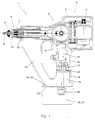
- the single figure shows the rivet setting device according to the invention in a sectional view.
- the rivet setting tool 1 has a housing 2 in which a drive motor 3 is arranged is.
- the drive motor 3 is an electric motor
- the crank drive 5 via a transmission 4 drives with which the rivet setting device 6 is driven.
- the rivet setting device 6 has a traction screw 7, not shown in detail.
- FIG. 1 there is a mouthpiece 8 the rivet setting device is also shown in a sectional view.
- the mouthpiece 8 there is a rivet 9.
- the rivet shown in FIG. 1 has not yet been installed.
- a rivet pin 10 extends into the mouthpiece 8.
- the tension spindle 7 has a passage 11 through which the rivet pin 10 can pass after tearing the inside of the housing 2 of the rivet setting tool 1 falls.
- the housing 2 has a rivet collecting container 12. This is integral with the housing 2 trained.
- the rivet holder 12 has an emptying opening 13 on.
- the housing 2 also has a handle 14 in which a push button switch 15 is included, which can be actuated by a button 16.
- contacts 17 arranged in the handle. The contacts 17 are with the key switch 15 and the motor 3 via electrical lines, not shown, in connection.
- a receptacle 18 is provided, in which a pin-shaped projection 19 one Power supply unit 20 can be used.
- the power supply unit 20 has a housing 21, which also has the projection 19 forms. On the projection 19 of the housing 21 there are also contacts 22 attached, which are in contact with the contacts 17 when the projection 19th is in the receptacle 18.
- Rechargeable batteries are located in the housing 21 of the power supply unit 20, which are not shown in detail. These batteries are with the contacts 22 in Connection. By pressing the key 16 and thus also the key switch 15 the batteries are brought into electrical contact with the motor 3 via the contacts 17 and 22 be so that the motor 3 by the batteries in a known manner with electricity can be supplied.
- the housing 21 of the power supply unit 20 also has a Face 23, which is substantially perpendicular to the longitudinal extension of the projection 19 extends. This end face 23 also forms a cover 24 for the rivet pin receptacle 12th
- This lid 24 also forms a bottom for the rivet holder 12, since the power supply unit 20 below the The rivet holder 12 is arranged.
- the rivet pin receptacle 12 opens out with its Drain opening 13 and the receptacle 18 in a common plane in the Level of the end face 23 of the power supply unit 20 when the power supply unit is plugged in 20 lies.
- the power supply unit 20 is interchangeable and removable on the rivet setting tool 1 attached. You can by simply inserting the projection 19 into the receptacle 18 can be mounted on the rivet setting tool 1. By inserting the contacts 22 and 17 brought into electrical contact. By simply pulling it out Power supply unit 20 can be removed from the rivet setting device 1.
- a partial one Securing device 25 shown with securing brackets ensures that the inserted Power supply unit 20 is not inadvertently removed from the rivet setting tool 1 falls out.
- the power supply unit 20 In order to put the rivet setting tool 1 into operation, the power supply unit 20 is also used its projection 19 is inserted into the receptacle 18. This brings the contacts 22 and 17 in contact.
- the power supply unit 20 can by the in its housing 21st supplied batteries supply the motor 3 with electrical current.
- the rivet holder 12 By inserting the power supply unit 20 into the housing 2 of the rivet setting tool 1, the rivet holder 12 is closed at the same time, in which the Emptying opening 13 is closed by the end face 23. During operation torn rivet pins 10 fall through the passage 11 into the rivet pin receptacle 12. The rivet pins 10 are collected there.
- the rivet pin receptacle 12 is dimensioned so that it is one Amount of rivets 10 can accommodate, which corresponds approximately to the amount of rivets that can be set with the current capacity of the power supply unit 20.
- the rivet setting device ensures that an operable Rivet setting tool, d. H. if the power supply unit 20 is inserted, too at the same time the rivet holder 12 is closed by the lid 24.
- the power supply unit 20 In operational condition, i.e. H. when the power supply unit 20 is in the rivet setting tool 1, it is advantageous that the power supply unit 20 below of the rivet pin receptacle 12 and below the engine 3, the transmission 4, crank mechanism 5 and the rivet setting device 6.
- the handle is between the power supply unit 20 and the motor 3 arranged. Since it is both the power supply unit 20, as well as the engine 3, the transmission 4, the crank mechanism 5 or the Rivet setting device 6 is relatively heavy components, can be in this way better weight distribution of the rivet setting tool 1 above and below the handle Reach 14. This improves the handling of the rivet setting tool 1.
Abstract
Description
Die Erfindung bezieht sich auf ein Nietsetzgerät mit einer auswechselbar am Nietsetzgerät anbringbaren Stromversorgungseinheit, die wenigstens eine vorzugsweise wieder aufladbare Batterie aufweist und mit der durch Anbringen am Nietsetzgerät das Nietsetzgerät in einen betriebsfähigen Zustand überführbar ist, und mit einem Nietstiftauffangbehälter, der zumindest eine verschließbare Entleerungsöffnung aufweist.The invention relates to a rivet setting tool with a replaceable on the rivet setting tool attachable power supply unit, the at least one preferably again has rechargeable battery and with that by attaching it to the rivet setting tool Rivet setting tool can be brought into an operational state, and with a rivet holder, which has at least one closable emptying opening.
Derartige Nietsetzgeräte sind aus dem Stand der Technik allgemein bekannt. Sie werden dazu verwendet, um z. B. Blindniete zu setzen. Durch die Stromversorgungseinheit wird die elektrisch betriebene Antriebsmechanik des Nietsetzgerätes gespeist. Derartige Nietsetzgeräte können aufgrund der auswechselbaren Stromversorgungseinheit netzunabhängig betrieben werden. Sie eignen sich daher insbesondere zum Betrieb auf Baustellen, wo häufig keine ausreichende Stromversorgung vorhanden ist. Auch beim industriellen Einsatz derartiger Nietsetzgeräte erweist sich die auswechselbare Stromversorgungseinheit als vorteilhaft. Da die Nietsetzgeräte netzunabhängig betrieben werden können, erübrigen sich Stromkabel, die bei der Handhabung des Nietsetzgerätes nachteilig sind. Daher eignen sich solche Nietsetzgeräte insbesondere für den Einsatz bei der Montage, insbesondere schwer zugänglicher Bauteile, wie z.B. Fahrzeugkarosserien in Fertigungsstraßen.Such rivet setting tools are generally known from the prior art. you will be used to z. B. To put blind rivets. Through the power supply unit the electrically operated drive mechanism of the rivet setting tool is fed. Such Rivet setting tools can be network-independent due to the exchangeable power supply unit operate. They are therefore particularly suitable for operation Construction sites where there is often no adequate power supply. Also at The replaceable power supply unit proves to be of industrial use for such rivet setting tools as beneficial. Since the rivet setting tools are operated independently of the mains can, there is no need for power cables when handling the rivet setting tool are disadvantageous. Such rivet setting tools are therefore particularly suitable for use during assembly, especially of difficult-to-access components, e.g. Vehicle bodies in production lines.
Durch den Nietstiftauffangbehälter soll verhindert werden, daß nach dem Setzen des Nietes die Nietstifte aus dem Nietsetzgerät herausfallen. Die Nietstiftauffangbehälter werden üblicherweise von den Bedienpersonen am Nietsetzgerät auswechselbar angebracht. Da die Nietstifte scharfkantig sind, stellen sie ein erhebliches Verietzungsrisiko dar. Beim Einsatz in Fertigungsstraßen hat sich gezeigt, daß die Auffangbehälter von den Bedienpersonen häufig nicht am Nietsetzgerät montiert werden. Dadurch fallen die Nietstifte auf den Boden der Arbeitsstation. Dies kann zu Verletzungen führen. Auch kann es vorkommen, daß die Nietstifte im zu montierenden Werkstück, wie z. B. Autokarosserien und dergleichen, verbleiben und nach Beendigen der Montage zu unerwünschten Klappergeräuschen führen können. Zumeist muß der montierte Gegenstand dann demontiert werden, um den Nietstift zu entfernen. The rivet holder is to prevent that after the The rivet pins fall out of the rivet setting tool. The rivet holder are usually exchangeably attached to the rivet setting tool by the operators. Since the rivet pins are sharp-edged, they pose a considerable risk of injury When used in production lines, it has been shown that the receptacles from the operators are often not mounted on the rivet setting tool. Thereby the fall Rivet pins on the floor of the work station. This can lead to injuries. Also it can happen that the rivet pins in the workpiece to be assembled, such as. B. Car bodies and the like, remain and undesirable after completion of the assembly Can cause rattling noises. Mostly, the assembled item then disassembled to remove the rivet pin.
Aufgabe der Erfindung ist es daher, ein Nietsetzgerät der eigens genannten Art derart weiterzuentwickeln, daß die Nietstifte zuverlässig vom Nietauffangbehälter aufgefangen werden.The object of the invention is therefore to provide a rivet setting tool of the type mentioned specifically to further develop that the rivet pins reliably caught by the rivet collecting container become.
Die Aufgabe wird erfindungsgemäß dadurch gelöst, daß die Stromversorgungseinheit zumindest im betriebsfähigen Zustand einen Deckel bildet, der die Entleerungsöffnung verschließt.The object is achieved in that the power supply unit at least in the operable condition forms a cover that the emptying opening closes.
Dies Lösung ist einfach und hat den Vorteil, daß im betriebsfähigen Zustand des Nietsetzgerätes automatisch die Entleerungsöffnung verschlossen ist, so daß die Nietstifte zuvertässig im Nietstiffauffangbehälter aufgefangen werden. Wenn die Stromversorgungseinheit nicht am Nietsetzgerät angebracht ist, kann das Nietsetzgerät nicht betrieben werden. Sobald die Stromversorgungseinheit am Nietsetzgerät angebracht ist, ist auch gleichzeitig die Entleerungsöffnung verschlossen. Auf diese Weise wird immer sichergestellt, daß der Nietstiftauffangbehälter immer dann geschlossen ist, wenn das Nietsetzgerät sich in einem betriebsfähigen Zustand befindet. Dadurch läßt sich die Unfallgefahr aufgrund herumliegender Nietstifte verringern und gleichzeitig verhindern, daß Nietstifte ungewollt in die miteinander zu vernietende Gegenstände hineinfallen.This solution is simple and has the advantage that in the operational state of the rivet setting tool the drain opening is automatically closed so that the rivet pins be reliably caught in the rivet pin collector. If the power unit is not attached to the rivet setting tool, the rivet setting tool cannot be operated become. As soon as the power supply unit is attached to the rivet setting tool also closed the drain opening at the same time. In this way it is always ensured that the pin holder is always closed when that Rivet setting tool is in an operational condition. This allows the Reduce risk of accident due to rivet pins lying around while preventing that rivet pins accidentally fall into the objects to be riveted together.
In einer vorteilhaften Weiterbildung kann das Nietsetzgerät Kontakte aufweisen, die im betriebsfähigen Zustand des Nietsetzgeräts mit Kontakten der Stromversorgungseinheit in Verbindung stehen. Dadurch läßt sich die Funktionsweise der Erfindung zusätzlich sicherstellen. Erst im betriebsfähigen Zustand entsteht ein Kontakt zwischen dem Kontakt in der Stromversorgungseinheit und dem Kontakt am Nietsetzgerät.In an advantageous development, the rivet setting tool can have contacts that are in the operational condition of the rivet setting tool with contacts of the power supply unit keep in touch. In this way, the mode of operation of the invention can additionally be ensured. A contact between the contact only arises when it is operational in the power supply unit and the contact on the rivet setting tool.
Um das Nietsetzgerät besonders kompakt auszubilden, kann der Nietauffangbehälter Einstückig mit einem Gehäuse des Nietsetzgerätes ausgebildet sein. Auch läßt sich dadurch verhindern, daß der Nietauffangbehälter von den Bedienpersonen nicht am Nietsetzgerät angebracht wird. Durch das einstückige Ausbilden mit dem Gehäuse wird sichergestellt, daß der Nietauffangbehälter immer am Nietsetzgerät angebracht ist.To make the rivet setting tool particularly compact, the rivet collecting container can Be formed in one piece with a housing of the rivet setting tool. This also allows prevent the rivet collecting container from being pulled by the rivet setting tool is attached. The one-piece construction with the housing ensures that the rivet collector is always attached to the rivet setting tool.
In einer vorteilhaften Weiterbildung kann die Stromversorgungseinrichtung zum Anbringen am Nietsetzgerät in das Gehäuse einsteckbar sein. Dadurch läßt sich der Bedingungskomfort des Nietsetzgerätes erhöhen. Durch einfaches Einstecken der Stromversorgungseinrichtung ins Nietsetzgerät kann der betriebsfähige Zustand hergestellt werden.In an advantageous development, the power supply device can be attached be insertable into the housing on the rivet setting tool. This allows the comfort of conditions of the rivet setting tool. By simply plugging in the power supply device The operational condition can be established in the rivet setting tool.
Vorteilhaft kann es dabei sein, wenn das Gehäuse einen Griff aufweist, und die Stromversorgungseinheit in den Griff einsteckbar ist. Dadurch läßt sich das Nietsetzgerät besonders kompakt gestalten. In einer vorteilhaften Weiterbildung kann dabei der Griff eine Aufnahme aufweisen, in welche ein im wesentlichen zapfenförmiger Vorsprung der Stromversorgungseinheit einsteckbar ist. Dadurch läßt sich das Nietsetzgerät auf einfache Weise besonders stabil ausgestalten.It can be advantageous if the housing has a handle and the power supply unit can be inserted into the handle. This makes the rivet setting tool particularly easy make compact. In an advantageous development, the handle can be a Have receptacle in which a substantially cone-shaped projection Power supply unit can be inserted. This makes the rivet setting tool simple Design particularly stable.
Um das Nietsetzgerät kompakter gestalten zu können, kann es sich als Vorteil erweisen, wenn die Stromversorgungseinheit bei Betrieb des Nietsetzgerätes unterhalb des Nietauffangbehälters angeordnet ist. Da die Stromversorgungseinheit üblicherweise recht schwer ist im Vergleich zum Nietsetzgerät selbst, läßt sich dadurch auch die Handhabung des Nietsetzgerätes vereinfachen.In order to make the rivet setting tool more compact, it can prove to be an advantage if the power supply unit when operating the rivet setting device below the Rivet collecting container is arranged. Because the power supply unit is usually is quite difficult compared to the rivet setting tool itself, which also makes it possible Simplify handling of the rivet setting tool.
Als vorteilhaft kann es sich Zudem erweisen, wenn beim Betrieb des Nietsetzgerätes die den Deckel bildende Stromversorgungseinheit wenigstens abschnittsweise den Boden des Nietstiftauffangbehälters bildet. Dadurch läßt sich der Nietstiftauffangbehälter auf einfache Weise entleeren, in dem die Stromversorgungseinheit abgenommen wird. Die Nietstifte fallen dann durch die Schwerkraft nach unten durch die Entleerungsöffnung des Nietstiftauffangbehälters.It can also prove to be advantageous if, during operation of the rivet setting tool the power supply unit forming the cover, at least in sections, the floor of the rivet holder. This allows the rivet holder to open empty in a simple manner by removing the power supply unit. The Rivet pins then fall down through the drain opening due to gravity of the rivet holder.
Auch kann es sich als vorteilhaft erweisen, wenn der Deckel bzw. Boden durch ein Gehäuse der Stromversorgungseinrichtung gebildet wird. Wenn die Stromversorgungseinrichtung ein solches Gehäuse aufweist, kann ihre Form besser an die Form des Nietsetzgerätes angepaßt werden. Außerdem können die Batterien in dem Gehäuse angeordnet werden und sind dadurch geschützt.It can also prove to be advantageous if the cover or base is covered by a housing the power supply device is formed. If the power supply device has such a housing, their shape can better match the shape of the rivet setting tool be adjusted. The batteries can also be arranged in the housing are and are protected by it.
Um ein sicheres Auffangen der Nietstifte beim Betrieb des Nietsetzgerätes zu gewährleisten, kann der Nietstiftauffangbehälter beim Betrieb des Nietsetzgerates unterhalb einer Zugspindel des Nietsetzgerätes angeordnet sein. Dann fallen die Nietstifte automatisch durch die Schwerkraft in den Nietstiftauffangbehälter. To ensure that the rivet pins are securely caught when the rivet setting tool is in operation, the rivet holder can be used when operating the rivet setting tool below one Tension spindle of the rivet setting device. Then the rivet pins fall automatically by gravity in the rivet holder.
In einer vorteilhaften Weiterbildung der Erfindung kann das Gehäuse als Hohlkörper ausgebildet sein, das den Nietstiftauffangbehälter zumindest abschnittsweise begrenzt. Dann läßt sich der Nietstiftauffangbehälter integral mit dem Gehäuse ausbilden. Auf diese Weise kann verhindert werden, daß das Nietsetzgerät auch ohne den Nietstiftauffangbehälter betrieben wird.In an advantageous development of the invention, the housing can be a hollow body be formed, which limits the rivet pin receptacle at least in sections. Then the rivet holder can be integrally formed with the housing. To this In this way, the rivet setting tool can be prevented even without the pin holder is operated.
Von Vorteil kann es zudem sein, wenn das Gehäuse der Stromversorgungseinheit einen Stimflächenabschnitt aufweist, der den Boden bzw. Deckel bildet und sich im wesentlichen senkrecht zum Vorsprung der Stromversorgungseinrichtung erstreckt. Dadurch läßt sich das Gehäuse der Stromversorgungseinheit geometrisch einfach gestalten. Zudem kann durch einfaches Einstecken des Vorsprunges der Stromversorgungseinrichtung in die Aufnahme die Entleerungsöffnung des Nietstiftauffangbehälters geschlossen werden. Ebenso kann durch einfaches Herausziehen der Stromversorgungseinheit der Nietstiftauffangbehälter geöffnet werden.It can also be advantageous if the housing of the power supply unit is one Has end face portion, which forms the bottom or cover and essentially extends perpendicular to the projection of the power supply device. Thereby the housing of the power supply unit can be geometrically simple. In addition can by simply plugging the projection of the power supply device closed in the receptacle, the drain opening of the rivet holder become. Likewise, by simply pulling out the power supply unit The rivet holder is opened.
In einer vorteilhaften Weiterbildung der Erfindung kann es sich als günstig erweisen, wenn der Nietstiftauffangbehälter in die Aufnahme mündet. Dadurch läßt sich Material zur Herstellung des Gehäuses des Nietsetzgerätes einsparen. Auch kann dadurch die Entleerungsöffnung des Nietstiftauffangbehälters vergrößert werden, da sie auch an den Vorsprung der Stromversorgungseinheit angrenzt und der Vorsprung der Stromversorgungseinheit dadurch abschnittsweise auch den Nietstiftauffangbehälter verschließt.In an advantageous development of the invention, it can prove to be advantageous when the rivet holder opens into the receptacle. This allows material save for the manufacture of the housing of the rivet setting tool. This can also help Emptying opening of the rivet pin receptacle can be enlarged, since they also on the Projection of the power supply unit is adjacent and the projection of the power supply unit thereby also partially closing the rivet holder.
Um das Nietsetzgerät besonders kompakt zu gestalten, kann es sich als vorteilhaft erweisen, wenn der Nietstiftauffangbehälter und der Griff zur Stromversorgungseinheit hin zusammenlaufen. Dadurch läßt sich das Nietsetzgerät besonders einfach gestalten.In order to make the rivet setting tool particularly compact, it can prove to be advantageous when the pin holder and the handle towards the power supply unit converge. This allows the rivet setting tool to be designed particularly simply.
In einer vorteilhaften Weiterbildung der Erfindung kann wenigstens eine Verriegelungseinrichtung vorgesehen sein, mit der die Stromversorgungseinheit im betriebsfähigen Zustand am Gehäuse sicherbar ist. Dadurch laßt sich verhindern, daß der Nietstiftauffangbehälter unbeabsichtigt geöffnet wird, indem die Stromversorgungseinheit vom Griff abfällt.In an advantageous development of the invention, at least one locking device can be provided with which the power supply unit in operational Condition on the housing can be secured. This can prevent the rivet holder is accidentally opened by pulling the power unit off the handle falls off.
Die Erfindung wird nachfolgend anhand eines Ausführungsbeispiels naher erläutert. The invention is explained in more detail below using an exemplary embodiment.
Die einzige Figur zeigt das erfindungsgemäße Nietsetzgerät in einer Schnittansicht.The single figure shows the rivet setting device according to the invention in a sectional view.
Das Nietsetzgerät 1 verfügt über ein Gehäuse 2, in dem ein Antriebsmotor 3 angeordnet
ist. Der Antriebsmotor 3 ist ein Elektromotor, der über ein Getriebe 4 einen Kurbeltrieb 5
antreibt, mit dem die Nietsetzeinrichtung 6 angetrieben wird. Die Nietsetzeinrichtung 6
verfügt über eine nicht näher dargestellte Zugspindel 7. In Figur 1 ist ein Mundstück 8
der Nietsetzeinrichtung ebenfalls in einer Schnittansicht dargestellt. In dem Mundstück 8
befindet sich eine Niet 9. Der in Figur 1 dargestellte Niet ist noch nicht montiert. Ein Nietstift
10 erstreckt sich in das Mundstück 8 hinein. Die Zugspindel 7 weist einen Durchgang
11 auf, durch welchen der Nietstift 10 nach dem Abreißen hindurchtreten kann in
das innere des Gehäuses 2 des Nietsetzgerätes 1 fällt.The
Die Anordnung, bestehend aus Elektromotor 3, Getriebe 4, Kurbeltrieb 5 und Nietsetzeinrichtung
6, funktioniert in bekannter Weise und wird daher nicht näher erläutert.The arrangement, consisting of
Das Gehäuse 2 weist einen Nietauffangbehälter 12 auf. Dieser ist integral mit dem Gehäuse
2 ausgebildet. Der Nietstiftauffangbehälter 12 weist eine Entleerungsöffnung 13
auf. Das Gehäuse 2 weist darüber hinaus einen Griff 14 auf, in dem ein Tastschalter 15
aufgenommen ist, der durch eine Taste 16 betätigbar ist. Darüber hinaus sind Kontakte
17 im Griff angeordnet. Die Kontakte 17 stehen mit dem Tastschalter 15 und dem Motor
3 über nicht näher dargestellte elektrische Leitungen in Verbindung. Im Griff 14 ist dar-über
hinaus eine Aufnahme 18 vorgesehen, in die ein zapfenförmiger Vorsprung 19 einer
Stromversorgungseinheit 20 einsetzbar ist.The
Die Stromversorgungseinheit 20 verfügt über ein Gehäuse 21, welches auch den Vorsprung
19 bildet. Am Vorsprung 19 des Gehäuses 21 sind darüber hinaus Kontakte 22
angebracht, die mit den Kontakten 17 in Verbindung stehen, wenn der Vorsprung 19
sich in der Aufnahme 18 befindet.The power supply unit 20 has a housing 21, which also has the
Im Gehäuse 21 der Stromversorgungseinheit 20 befinden sich wiederaufladbare Batterien,
die nicht näher dargestellt sind. Diese Batterien stehen mit den Kontakten 22 in
Verbindung. Durch Betätigen der Taste 16 und somit auch des Tastschalters 15 können
die Batterien über die Kontakte 17 und 22 mit dem Motor 3 in elektrischen Kontakt gebracht
werden, so daß der Motor 3 durch die Batterien in bekannter Weise mit Strom
versorgt werden kann.Rechargeable batteries are located in the housing 21 of the power supply unit 20,
which are not shown in detail. These batteries are with the
Das Gehäuse 21 der Stromversorgungseinheit 20 verfügt darüber hinaus über eine
Stimfläche 23, die sich im wesentlichen senkrecht zur Längserstreckung des Vorsprunges
19 erstreckt. Diese Stimfläche 23 bildet gleichzeitig einen Deckel 24 für den Nietstiftauffangbehälter
12.The housing 21 of the power supply unit 20 also has a
Face 23, which is substantially perpendicular to the longitudinal extension of the
Dieser Deckel 24 bildet auch gleichzeitig einen Boden für den Nietstiftauffangbehälter
12, da beim Betrieb des Nietsetzgerätes die Stromversorgungseinheit 20 unterhalb des
Nietstiftauffangbehälters 12 angeordnet ist.This lid 24 also forms a bottom for the
Wie in Figur 1 gut zu erkennen ist, münden der Nietstiftauffangbehälter 12 mit seiner
Entleerungsöffnung 13 und die Aufnahme 18 in eine gemeinsame Ebene, die in der
Ebene der Stirnfläche 23 der Stromversorgungseinheit 20 bei eingesteckter Stromversorgungseinheit
20 liegt.As can be clearly seen in FIG. 1, the
Die Stromversorgungseinheit 20 ist austauschbar und herausnehmbar am Nietsetzgerät
1 angebracht. Sie kann durch einfaches Einstecken des Vorsprunges 19 in die Aufnahme
18 am Nietsetzgerät 1 montiert werden. Durch das Einstecken werden die Kontakte
22 und 17 in elektrischen Kontakt gebracht. Durch einfaches Herausziehen kann die
Stromversorgungseinheit 20 vom Nietsetzgerät 1 abgenommen werden. Eine teilweise
dargestellte Sicherungsvorrichtung 25 mit Sicherungsbügeln gewährleistet, daß die eingesteckte
Stromversorgungseinheit 20 nicht unbeabsichtigt aus dem Nietsetzgerät 1
herausfällt.The power supply unit 20 is interchangeable and removable on the
Durch das Einstecken der Stromversorgungseinheit 20 in das Gehäuse 2 des Nietsetzgerätes
1 wird nicht nur ein elektrischer Kontakt zwischen den Kontakten 22 und 17
hergestellt, sondern auch gleichzeitig die Entleerungsöffnung 13 durch die Stirnfläche
23 verschlossen.By plugging the power supply unit 20 into the
Nachfolgend wird die Wirkungs und funktionsweise der Erfindung näher erläutert. The effect and mode of operation of the invention are explained in more detail below.
Um das Nietsetzgerät 1 in Betrieb zu nehmen, wird die Stromversorgungseinheit 20 mit
ihrem Vorsprung 19 in die Aufnahme 18 eingesteckt. Dadurch gelangen die Kontakte 22
und 17 in Kontakt. Die Stromversorgungseinheit 20 kann durch die in ihrem Gehäuse 21
aufgenommenen Batterien den Motor 3 mit elektrischem Strom versorgen.In order to put the
Im eingesteckten Zustand der Stromversorgungseinheit kann durch Betätigen der Taste
16 durch die den Griff haltende Hand einer Bedienperson mit Tastschalter 15 betätigt
werden, der eine elektrische Verbindung zwischen den Batterien und dem Motor 3 herstellt.
Motor 3 kann dann durch das Getriebe 4 und den Kurbeltrieb 5, sowie die
Nietsetzeinrichtung 6 einen Niet in bekannter Weise setzen.When the power supply unit is plugged in, you can press the
Durch das Einsetzen der Stromversorgungseinheit 20 in das Gehäuse 2 des Nietsetzgerätes
1 wird auch gleichzeitig der Nietstiftauffangbehälter 12 geschlossen, in dem die
Entleerungsöffnung 13 durch die Stirnfläche 23 verschlossen wird. Während des Betriebs
fallen abgerissene Nietstifte 10 durch den Durchgang 11 in den Nietstiftauffangbehälter
12. Die Nietstifte 10 werden dort gesammelt.By inserting the power supply unit 20 into the
Sobald der Nietstiftauffangbehälter 12 gefüllt ist, kann er durch herausziehen der
Stromversorgungseinheit 20 aus dem Griff geöffnet werden, so daß die gesammelten
Nietstifte 10 aus dem Nietstiftauffangbehälter 12 herausfallen und z. B. entsorgt werden
können. Der Nietstiftauffangbehälter 12 ist darüber so bemessen, daß er eine solche
Menge an Nietstiften 10 aufnehmen kann, die in etwa der Menge an Niete entspricht, die
mit der Stromkapazität der Stromversorgungseinheit 20 setzbar ist.Once the
Durch das erfindungsgemäße Nietsetzgerät wird sichergestellt, daß bei einem betriebsfähigen
Nietsetzgerät, d. h. wenn die Stromversorgungseinheit 20 eingesetzt ist, auch
gleichzeitig der Nietstiftauffangbehälter 12 durch den Deckel 24 verschlossen ist.The rivet setting device according to the invention ensures that an operable
Rivet setting tool, d. H. if the power supply unit 20 is inserted, too
at the same time the
Im betriebsfähigen Zustand, d. h. wenn sich die Stromversorgungseinheit 20 im Nietsetzgerät
1 befindet, ist es vorteilhaft, daß die Stromversorgungseinheit 20 unterhalb
des Nietstiftauffangbehälters 12 und unterhalb des Motors 3, des Getriebes 4, Kurbeltriebs
5 und der Nietsetzeinrichtung 6 befindet. Der Griff ist zwischen der Stromversorgungseinheit
20 und dem Motor 3 angeordnet. Da es sich sowohl bei der Stromversorgungseinheit
20, als auch beim Motor 3, dem Getriebe 4, dem Kurbeltrieb 5 oder der
Nietsetzeinrichtung 6 um relativ schwere Bauteile handelt, läßt sich auf diese Weise eine
bessere Gewichtsverteilung des Nietsetzgerätes 1 oberhalb und unterhalb des Griffes
14 erreichen. Dadurch verbessert sich die Handhabung des Nietsetzgerätes 1.In operational condition, i.e. H. when the power supply unit 20 is in the
Die Anmelderin weist ausdrücklich darauf hin, daß sämtliche Merkmale, wie sie in den Haupt- und Unteransprüchen genannt sind, erfindungswesentlich sind. Der Fachmann soll auch dazu angeregt werden, die Anzahl der zur Durchführung der Erfindung erforderlichen Merkmale möglichst gering zu halten.The applicant expressly draws attention to the fact that all the features as described in the Main and dependent claims are mentioned, are essential to the invention. The expert should also be suggested to the number of those required to implement the invention Keep characteristics as low as possible.
Claims (15)
Applications Claiming Priority (2)
| Application Number | Priority Date | Filing Date | Title |
|---|---|---|---|
| DE19806051 | 1998-02-13 | ||
| DE19806051A DE19806051A1 (en) | 1998-02-13 | 1998-02-13 | Rivet setting tool |
Publications (2)
| Publication Number | Publication Date |
|---|---|
| EP0936006A2 true EP0936006A2 (en) | 1999-08-18 |
| EP0936006A3 EP0936006A3 (en) | 2000-11-29 |
Family
ID=7857704
Family Applications (1)
| Application Number | Title | Priority Date | Filing Date |
|---|---|---|---|
| EP99101151A Withdrawn EP0936006A3 (en) | 1998-02-13 | 1999-01-21 | Rivet setting tool |
Country Status (6)
| Country | Link |
|---|---|
| US (1) | US6026551A (en) |
| EP (1) | EP0936006A3 (en) |
| JP (1) | JP3235826B2 (en) |
| AU (1) | AU715770B2 (en) |
| BR (1) | BR9900651A (en) |
| DE (1) | DE19806051A1 (en) |
Cited By (2)
| Publication number | Priority date | Publication date | Assignee | Title |
|---|---|---|---|---|
| US6886226B1 (en) | 1999-10-02 | 2005-05-03 | Textron Fastening Systems Limited | Riveting apparatus |
| US10010066B2 (en) | 2014-04-23 | 2018-07-03 | Ridge Tool Company | Hydraulic press tool |
Families Citing this family (8)
| Publication number | Priority date | Publication date | Assignee | Title |
|---|---|---|---|---|
| DE19818755A1 (en) * | 1998-04-27 | 1999-11-04 | Honsel M H Beteiligungs Gmbh | Rivet setting tool |
| DE19818757A1 (en) * | 1998-04-27 | 1999-11-04 | Honsel M H Beteiligungs Gmbh | Rivet setting tool |
| DE19903020A1 (en) | 1999-01-26 | 2000-08-03 | Honsel M H Beteiligungs Gmbh | Rivet setting tool |
| US6383189B1 (en) * | 1999-09-13 | 2002-05-07 | Brian Schumacher | Driver tool for bone distractor with shaft extension |
| US7802352B2 (en) * | 2005-04-13 | 2010-09-28 | Newfrey Llc | Monitoring system for fastener setting tool |
| CN101224487B (en) * | 2008-01-25 | 2010-07-28 | 孙延新 | Drive of easy squeeze blind rivet gun |
| WO2021247876A1 (en) | 2020-06-03 | 2021-12-09 | Milwaukee Electric Tool Corporation | Rivet setting tool |
| CN116060570A (en) * | 2023-03-07 | 2023-05-05 | 峰范新能源汽车技术(太仓)有限公司 | Multifunctional spare and accessory part riveting device |
Citations (4)
| Publication number | Priority date | Publication date | Assignee | Title |
|---|---|---|---|---|
| US4137747A (en) * | 1977-03-22 | 1979-02-06 | Aerpat A.G. | Collector for broken-off fastener parts |
| GB2116102A (en) * | 1982-03-08 | 1983-09-21 | Avdel Ltd | Riveting tool |
| US4887450A (en) * | 1988-03-31 | 1989-12-19 | Textron, Inc. | Fastener stem collection apparatus and method |
| EP0527414A1 (en) * | 1991-08-12 | 1993-02-17 | GESIPA Blindniettechnik GmbH | Blind-rivet tool |
Family Cites Families (2)
| Publication number | Priority date | Publication date | Assignee | Title |
|---|---|---|---|---|
| FR2677908B1 (en) * | 1991-06-20 | 1995-04-07 | Hydr Am | VERSATILE SELF-CONTAINED TOOL SUCH AS SHEARS / HYDRAULICALLY CONTROLLED SPREADERS. |
| US5553478A (en) * | 1994-04-08 | 1996-09-10 | Burndy Corporation | Hand-held compression tool |
-
1998
- 1998-02-13 DE DE19806051A patent/DE19806051A1/en not_active Ceased
-
1999
- 1999-01-21 EP EP99101151A patent/EP0936006A3/en not_active Withdrawn
- 1999-02-11 US US09/249,245 patent/US6026551A/en not_active Expired - Fee Related
- 1999-02-11 AU AU16385/99A patent/AU715770B2/en not_active Ceased
- 1999-02-12 BR BR9900651-0A patent/BR9900651A/en not_active IP Right Cessation
- 1999-02-15 JP JP03549699A patent/JP3235826B2/en not_active Expired - Fee Related
Patent Citations (4)
| Publication number | Priority date | Publication date | Assignee | Title |
|---|---|---|---|---|
| US4137747A (en) * | 1977-03-22 | 1979-02-06 | Aerpat A.G. | Collector for broken-off fastener parts |
| GB2116102A (en) * | 1982-03-08 | 1983-09-21 | Avdel Ltd | Riveting tool |
| US4887450A (en) * | 1988-03-31 | 1989-12-19 | Textron, Inc. | Fastener stem collection apparatus and method |
| EP0527414A1 (en) * | 1991-08-12 | 1993-02-17 | GESIPA Blindniettechnik GmbH | Blind-rivet tool |
Cited By (2)
| Publication number | Priority date | Publication date | Assignee | Title |
|---|---|---|---|---|
| US6886226B1 (en) | 1999-10-02 | 2005-05-03 | Textron Fastening Systems Limited | Riveting apparatus |
| US10010066B2 (en) | 2014-04-23 | 2018-07-03 | Ridge Tool Company | Hydraulic press tool |
Also Published As
| Publication number | Publication date |
|---|---|
| AU715770B2 (en) | 2000-02-10 |
| BR9900651A (en) | 2000-01-04 |
| JPH11290983A (en) | 1999-10-26 |
| JP3235826B2 (en) | 2001-12-04 |
| AU1638599A (en) | 1999-09-09 |
| DE19806051A1 (en) | 1999-08-26 |
| EP0936006A3 (en) | 2000-11-29 |
| US6026551A (en) | 2000-02-22 |
Similar Documents
| Publication | Publication Date | Title |
|---|---|---|
| DE60005074T2 (en) | Battery operated hand tool | |
| DE102005007925B4 (en) | suction device | |
| DE4038634C2 (en) | ||
| DE60223488T2 (en) | Portable container for an electric hand tool with the ability to vacuum and collect dust | |
| DE19905086A1 (en) | Battery operated, hand-held power tool | |
| EP2230164A1 (en) | Bicycle frame for holding a battery unit and accompanying battery unit | |
| DE7521237U (en) | BATTERY-DRIVEN MULTI-PURPOSE DEVICE IN PARTICULAR GRASS SHEARS DRILLING MACHINE ETC. | |
| EP0936006A2 (en) | Rivet setting tool | |
| EP0529266A1 (en) | Electric hand mixer | |
| DE2332630A1 (en) | MOTOR-DRIVEN MACHINE TOOLS, IN PARTICULAR HEDGE SHEARS | |
| EP1827767A1 (en) | Device for a hand-held machine-tool case | |
| DE3743083C2 (en) | Handheld vacuum cleaner | |
| EP2521477B1 (en) | Floor cleaning device | |
| EP0659064B1 (en) | Motor-driven appliance for personal use | |
| DE19622694B4 (en) | Industrial truck with a battery compartment | |
| DE20318187U1 (en) | Electric can opener | |
| DE7625946U1 (en) | FASTENING DEVICE FOR THE RELEASABLE ATTACHMENT OF AN UPPER HANDLE TO A PORTABLE, BATTERY-DRIVEN MACHINE MACHINE, IN PARTICULAR A GRASS SHEARS | |
| EP1926417B1 (en) | Mobile sweeping appliance with a pivotable grip | |
| EP1843436B1 (en) | Electrical coupling assembly | |
| DE102005060047B4 (en) | Remote control as a case for a hearing device | |
| EP2066202B1 (en) | Food processor comprising a pivotable cover for covering a coupling point | |
| DE3544891A1 (en) | ELECTRIC STIRRER | |
| WO2014040785A1 (en) | Vacuum cleaner | |
| DE1248875B (en) | Mains-independent, electromotive operated hand mixer | |
| DE202008008000U1 (en) | Unit of battery-operated hand-held electrical device and associated charging station |
Legal Events
| Date | Code | Title | Description |
|---|---|---|---|
| PUAI | Public reference made under article 153(3) epc to a published international application that has entered the european phase |
Free format text: ORIGINAL CODE: 0009012 |
|
| AK | Designated contracting states |
Kind code of ref document: A2 Designated state(s): DE ES FR GB IT NL SE |
|
| AX | Request for extension of the european patent |
Free format text: AL;LT;LV;MK;RO;SI |
|
| PUAL | Search report despatched |
Free format text: ORIGINAL CODE: 0009013 |
|
| AK | Designated contracting states |
Kind code of ref document: A3 Designated state(s): AT BE CH CY DE DK ES FI FR GB GR IE IT LI LU MC NL PT SE |
|
| AX | Request for extension of the european patent |
Free format text: AL;LT;LV;MK;RO;SI |
|
| 17P | Request for examination filed |
Effective date: 20001221 |
|
| AKX | Designation fees paid |
Free format text: DE ES FR GB IT NL SE |
|
| GRAH | Despatch of communication of intention to grant a patent |
Free format text: ORIGINAL CODE: EPIDOS IGRA |
|
| STAA | Information on the status of an ep patent application or granted ep patent |
Free format text: STATUS: THE APPLICATION IS DEEMED TO BE WITHDRAWN |
|
| 18D | Application deemed to be withdrawn |
Effective date: 20030911 |