EP0936766A1 - Satellite broadcasting system - Google Patents
Satellite broadcasting system Download PDFInfo
- Publication number
- EP0936766A1 EP0936766A1 EP98929837A EP98929837A EP0936766A1 EP 0936766 A1 EP0936766 A1 EP 0936766A1 EP 98929837 A EP98929837 A EP 98929837A EP 98929837 A EP98929837 A EP 98929837A EP 0936766 A1 EP0936766 A1 EP 0936766A1
- Authority
- EP
- European Patent Office
- Prior art keywords
- broadcasting
- satellite
- signal
- signals
- ground
- Prior art date
- Legal status (The legal status is an assumption and is not a legal conclusion. Google has not performed a legal analysis and makes no representation as to the accuracy of the status listed.)
- Granted
Links
Images


Classifications
-
- H—ELECTRICITY
- H04—ELECTRIC COMMUNICATION TECHNIQUE
- H04B—TRANSMISSION
- H04B1/00—Details of transmission systems, not covered by a single one of groups H04B3/00 - H04B13/00; Details of transmission systems not characterised by the medium used for transmission
- H04B1/69—Spread spectrum techniques
- H04B1/707—Spread spectrum techniques using direct sequence modulation
- H04B1/7073—Synchronisation aspects
- H04B1/7075—Synchronisation aspects with code phase acquisition
-
- H—ELECTRICITY
- H04—ELECTRIC COMMUNICATION TECHNIQUE
- H04B—TRANSMISSION
- H04B7/00—Radio transmission systems, i.e. using radiation field
- H04B7/14—Relay systems
- H04B7/15—Active relay systems
- H04B7/185—Space-based or airborne stations; Stations for satellite systems
- H04B7/18523—Satellite systems for providing broadcast service to terrestrial stations, i.e. broadcast satellite service
- H04B7/18526—Arrangements for data linking, networking or transporting, or for controlling an end to end session
-
- H—ELECTRICITY
- H04—ELECTRIC COMMUNICATION TECHNIQUE
- H04H—BROADCAST COMMUNICATION
- H04H20/00—Arrangements for broadcast or for distribution combined with broadcast
- H04H20/44—Arrangements characterised by circuits or components specially adapted for broadcast
- H04H20/46—Arrangements characterised by circuits or components specially adapted for broadcast specially adapted for broadcast systems covered by groups H04H20/53-H04H20/95
- H04H20/51—Arrangements characterised by circuits or components specially adapted for broadcast specially adapted for broadcast systems covered by groups H04H20/53-H04H20/95 specially adapted for satellite broadcast systems
-
- H—ELECTRICITY
- H04—ELECTRIC COMMUNICATION TECHNIQUE
- H04J—MULTIPLEX COMMUNICATION
- H04J13/00—Code division multiplex systems
- H04J13/16—Code allocation
Definitions
- the present invention relates to a satellite broadcasting system for broadcasting information such as video, audio, and data to a specific ground service area using a broadcasting satellite or a communication satellite on the geostationary orbit and, more particularly, to a system for multiplexing and broadcasting a plurality of channels by code division multiplex (CDM: Code Division Multiplex).
- CDM Code Division Multiplex
- orthogonal frequency division multiplex OFDM: Orthogonal Frequency Division Multiplex
- CDM Code Division Multiplex
- CDM requires a time as long as, e.g., ten-odd seconds until the receiver establishes spreading code synchronization for a broadcasting signal. For this reason, the receiver needs a long time from the start to completion of channel switching. The viewers must wait for a long time every time the channel is switched and feel displeased. In some cases, important information may be lost during the channel switching period, and a measure is necessary.
- the satellite broadcasting systems require use of a parabolic antenna having a diameter of about 40 to 50 cm or a planar array antenna almost equal in size as a reception antenna. In addition, unless the antenna is precisely directed to the satellite, no sufficient gain is obtained, and reception is disabled. These systems assume indoor reception/viewing, so it is hard to provide a satellite broadcasting receiver using a simple antenna system meeting requirements for use on a mobile or use as a portable device. An apparatus meeting these requirements can effectively function as a means for providing urgent information in disasters or the like and its implementation in the near future is awaited.
- the driver To receive the satellite broadcasting on a mobile such as an automobile, the driver must switch the reception channel in a number of channels, as described above. Since this channel selection operation is cumbersome and distracts the driver from driving, a traffic accident may be caused.
- a satellite broadcasting system for transmitting a plurality of broadcasting signals of a plurality of channels from a ground broadcasting station, repeating the broadcasting signals with a geostationary satellite, and broadcasting the broadcasting signals to a broadcasting receiver in a predetermined service area on the ground
- the ground broadcasting station comprising multiplex means for spreading spectra of the broadcasting signals using different spreading codes in units of channels and synthesizing the broadcasting channels to code-division-multiplex the broadcasting signals of the plurality of channels, and transmitting the broadcasting signals
- phase difference information transmission means for transmitting information representing a phase difference of the spreading codes between the broadcasting signals of the channels, which are multiplexed by the multiplex means, to notify the broadcasting receiver of the information
- the broadcasting receiver comprising phase difference information reception means for receiving the information representing the phase difference, and reception synchronization means for establishing spreading code synchronization for the channels of the code-division-multiplexed broadcasting signals received via the geo
- a satellite broadcasting system for transmitting a broadcasting signal of at least one channel from each of a plurality of ground broadcasting stations, repeating the broadcasting signals with a geostationary satellite, and broadcasting the broadcasting signals to a broadcasting receiver in a predetermined service area on the ground
- each of the plurality of ground broadcasting stations comprising transmission means for spreading, spectra of broadcasting signals to be transmitted from a self station using different spreading codes in units of channels and transmitting the broadcasting signals
- the geostationary satellite comprising phase difference detection means for receiving the broadcasting signals of the channels, which are transmitted from the plurality of ground broadcasting stations, and detecting a phase difference of the spreading codes between the broadcasting signals of the channels, and repeat transmission synchronization means for setting a phase relationship of the spreading codes between the channels of the broadcasting signals received from the plurality of ground broadcasting stations in a predetermined synchronization state on the basis of a detection result from the phase difference detection means and transmitting the broadcasting signals to the predetermined
- a satellite broadcasting system for transmitting a broadcasting signal of at least one channel from each of a plurality of ground broadcasting stations, repeating the broadcasting signals with a geostationary satellite, and broadcasting the broadcasting signals to a broadcasting receiver in a predetermined service area on the ground
- each of the plurality of ground broadcasting stations comprising transmission means for spreading spectra of broadcasting signals to be transmitted from a self station using different spreading codes in units of channels and transmitting the broadcasting signals
- transmission timing control means for variably controlling a transmission timing of the broadcasting signals to be transmitted by the transmission means in units of channels
- the geostationary satellite comprising phase difference detection means for receiving the broadcasting signals of the channels, which are transmitted from the plurality of ground broadcasting stations, and detecting a phase difference of the spreading codes between the broadcasting signals of the channels, and phase difference information notification means for supplying information representing the phase difference detected by the phase difference detection means to each of the ground broadcasting stations as sources, thereby causing the transmission timing control means to variably control the transmission timing such
- a radio receiver used in a radio communication system for radio-transmitting a predetermined transmission signal and carried by a mobile, comprising reception means for demodulating transmission data from the radio-transmitted transmission signal, storage means for storing the transmission data obtained by the reception means at least for a predetermined period, hit detection means for detecting a hit generated in the transmission signal received by the reception means, and compensation means for compensating transmission data corresponding to a transmission signal portion where the hit is detected by the hit detection means, on the basis of the transmission data stored in the storage means.
- a radio broadcasting system for radio-broadcasting a predetermined transmission signal from a radio broadcasting apparatus to a radio receiver, comprising reception means, arranged in the radio receiver, for demodulating transmission data from the radio-broadcasted transmission signal, delay means, arranged in the radio receiver, for delaying the transmission data obtained by the reception means at least for a predetermined period, hit detection means, arranged in the radio receiver, for detecting a hit generated in the transmission signal received by the reception means, retransmission request means, arranged in the radio receiver, for requesting the radio broadcasting apparatus to retransmit a transmission signal corresponding to a portion where the hit is detected by the hit detection means, retransmission means, arranged in the radio broadcasting apparatus, for transmitting the transmission signal corresponding to the requested portion using a predetermined retransmission channel in response to the retransmission request from the retransmission request means, and compensation means, arranged in the radio receiver, for compensating, in the transmission data delayed
- a radio receiver carried by a mobile and used in a radio broadcasting system for radio-broadcasting a predetermined transmission signal from a radio broadcasting apparatus to the radio receiver, comprising reception means for demodulating transmission data from the radio-broadcasted transmission signal, delay means for delaying the transmission data obtained by the reception means at least for a predetermined period, hit detection means for detecting a hit generated in the transmission signal received by the reception means, retransmission request means for requesting the radio broadcasting apparatus to retransmit a transmission signal corresponding to a portion where the hit is detected by the hit detection means, and compensation means for compensating, in the transmission data delayed by the delay means, transmission data corresponding to the transmission signal portion where the hit is detected by the hit detection means, using transmission data demodulated, by the reception means, from the transmission signal transmitted from the radio broadcasting apparatus in response to the request from the retransmission request means and arriving through a predetermined retransmission channel.
- a radio broadcasting apparatus used in a radio broadcasting system for radio-broadcasting a predetermined transmission signal from the radio broadcasting apparatus to a radio receiver, comprising means for receiving a retransmission request from the radio receiver, and retransmission means for transmitting a transmission signal of a requested portion using a predetermined retransmission channel in response to the request.
- a satellite broadcasting system for repeating a broadcasting signal transmitted from a ground broadcasting station with a satellite and broadcasting the broadcasting signal to a predetermined service area on the ground, comprising a gap filler apparatus comprising means for receiving the broadcasting signal repeated by the satellite, and means for radio-transmitting a signal having the same frequency as that of the broadcasting signal transmitted from the satellite, to an area in the service area, where the broadcasting signal from the satellite cannot be received.
- a gap filler apparatus used in a satellite broadcasting system for transmitting a broadcasting signal to a predetermined service area on the ground via a satellite, comprising a first antenna for receiving the broadcasting signal transmitted from the satellite, a radio circuit section for at least amplifying the broadcasting signal received by the first antenna and outputting a transmission broadcasting signal having the same frequency as that of the received broadcasting signal, and a second antenna for radio-transmitting the transmission broadcasting signal output from the radio circuit section to an area in the service area, where the broadcasting signal from the satellite cannot be received.
- a satellite broadcasting system comprising a first satellite placed in a predetermined orbit to transmit a broadcasting signal sent from a ground broadcasting station to a predetermined service area on the ground, and a second satellite placed in the same orbit as that of the first satellite while being spaced apart from the first satellite by a predetermined distance to synchronously transmit the same broadcasting signal as that transmitted from the first satellite to the service area.
- FIG. 1 is a schematic view showing a satellite broadcasting system according to the first embodiment of the present invention.
- Each of the ground broadcasting stations BC1 and BC2 of the first embodiment has a function of matching the phases of spreading codes between a plurality of channels when a plurality of programs are to be subjected to code division multiplex and transmitted and has the following arrangement.
- FIG. 2 is a block diagram showing the arrangement of the transmission section.
- Broadcasting signals of a plurality of programs (N programs in FIG. 2) edited by a circuit (not shown) are input to modulators 111 to 11n, respectively.
- the spread modulators 111 to 11n spread-spectrum-modulate the broadcasting signals using different spreading codes generated from spreading code generators 121 to 12n, respectively.
- the broadcasting signals spread-spectrum-modulated by the spread modulators 111 to 11n are synthesized into one code division multiplex (CDM) broadcasting signal by a synthesizer 131 and input to a modulator 132.
- the modulator 132 further modulates the CDM broadcasting signal by digital modulation such as QPSK or QAM.
- the modulated CDM broadcasting signal is frequency-converted into a Ka- or Ku-band radio signal by a transmitter 133.
- the radio signal is amplified to a predetermined transmission power level and then transmitted from an antenna 134 to the geostationary satellite.
- the broadcasting signals of the programs are spread-modulated by the spread modulators 111 to 11n using the spreading codes generated from the spreading code generators 121 to 12n in synchronism with the reference phase, respectively.
- the CDM broadcasting signal output from the synthesis circuit 131 has spreading code phases matched between the channels, so the CDM broadcasting signal having matched spreading code phases is broadcasted to the broadcasting receiver MS through the geostationary satellite SAT.
- Spreading code synchronization is established for one of the channels in the CDM broadcasting signal arriving through the geostationary satellite SAT upon, e.g., powering on, and then, the spreading codes corresponding to all channels are generated in phase. Even when switching to another channel is performed, the broadcasting receiver MS can receive the channel in a very short time only by switching the spreading code without newly establishing spreading code synchronization to the channel.
- a geostationary satellite SAT detects the spreading code phase difference between the channels of a CDM broadcasting signal arriving from each of a ground broadcasting station BC1 or BC2, matches the spreading code phases between the channels on the basis of the detection result, and then transmits a signal to a broadcasting receiver MS.
- FIG. 3 is a block diagram showing the arrangement of the geostationary satellite SAT according to the second embodiment.
- a CDM broadcasting signal transmitted from the ground broadcasting station BC1 or BC2 is received by a Ku-band reception antenna 151 and input to a reception circuit 152.
- the CDM broadcasting signal is low-noise-amplified, down-converted into an IF signal, and distributed to k correlators 161 to 16k.
- the number of correlators 161 to 16k is set in correspondence with a total number k of channels to be multiplexed/transmitted by the ground broadcasting station BC1 or BC2.
- the correlators 161 to 16k despread the spectrum of the received IF signal using spreading codes which are set in advance in units of channels.
- the despread reception signals are input to spread modulation circuits 171 to 17k, respectively.
- the frequency conversion circuit 154 frequency-converts the CDM broadcasting signal into a frequency in the S band (2.6 GHz), which is assigned to the self system in advance, and inputs the signal to a transmitter 155.
- the transmitter 155 amplifies the frequency-converted CDM broadcasting signal to a predetermined transmission power level and transmits the CDM broadcasting signal from an S-band transmission antenna 156 to a service area.
- the phase difference between the spreading codes of the channel signals in the CDM broadcasting signal transmitted from the ground broadcasting station BC1 or BC2 is detected in the geostationary satellite SAT.
- the spectra of the channel signals are spread again using spreading codes phase-controlled to make the detected phase difference zero and then transmitted to the service area in the S band. For this reason, even when the spreading code phases do not match between the channels of the CDM broadcasting signal arriving from the ground broadcasting station BC1 or BC2, the CDM broadcasting signal is transmitted and received by the broadcasting receiver MS after the phase difference is absorbed in the geostationary satellite SAT.
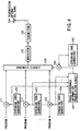
- FIG. 4 is a block diagram showing the arrangement of the transmission section of each of the ground broadcasting stations BC1 and BC2 according to this embodiment.
- the same reference numerals as in FIG. 2 denote the same parts in FIG. 4, and a detailed description thereof will be omitted.
- the synthesis circuit 135 synthesizes the spread-modulated signal of each of the channel broadcasting signals output from spread modulators 111 to 11n with the spread-modulated signal of the phase difference information output from the spread modulator 142 and supplies the synthesized signal to a modulator 132 for transmission.
- the broadcasting receiver MS has the following arrangement.
- FIG. 5 is a block diagram showing the arrangement of the broadcasting receiver MS.
- the CDM broadcasting signal arriving from the geostationary satellite SAT is received by an S-band reception antenna 191, input to a reception circuit 192, low-noise-amplified, and frequency-converted into an IF signal.
- the received IF signal is distributed to first and second correlators 193 and 194.
- the first correlator 193 despreads the spectrum of the received IF signal using a spreading code corresponding to a reception channel designated from a control circuit 190, and inputs the despread channel signal to a detector (DET) 195.
- the reception channel is designated by the user by operating a remote-control operation section 197.
- the detector 195 detects the channel signal by a detection method corresponding to, e.g., QPSK.
- the obtained received broadcasting signal is input to an audio/video separation circuit 1101.
- the second correlator 194 despreads the spectrum of the received IF signal output from the reception circuit 192 using a spreading code prepared in advance for transmission of phase difference information.
- the phase difference information signal obtained by despreading is detected by a detector 196, decoded, and input to the control circuit 190.
- the phase difference between the spreading codes of channels is detected, and the phase difference information is multiplexed on the CDM broadcasting signal and transmitted.
- the phase difference information is separated and extracted.
- the spectrum of each channel signal of the CDM broadcasting signal is newly spread, and the signal is transmitted to a service area.
- FIG. 6 is a block diagram showing the arrangement of the geostationary satellite SAT according to this embodiment.
- the same reference numeral as in FIG. 3 denote the same parts in FIG. 6, and a detailed description thereof will be omitted.
- the geostationary satellite SAT has not only a group of correlators 161 to 16k for despreading the spectra of the CDM broadcasting signal in units of channels but also a correlator 157 for separating and extracting the phase difference information.
- the correlator 157 despreads the spectrum of the received IF signal output from a reception circuit 152 using a spreading code which is set in advance for transmission of the phase difference information, thereby separating and extracting the phase difference information.
- a control circuit 181 generates phase control signals for designating the chip phases of the spreading codes of the channels on the basis of the phase difference information separated and extracted by the correlator 157 and supplies the phase control signals to spread modulation circuits 171 to 17k, respectively.
- Each of the spread modulation circuits 171 to 17k initializes the chip phase of the spreading code on the basis of the phase control signal and newly spreads the spectrum of the channel signal, which has temporarily been despread by a corresponding one of the correlators 161 to 16k, using the spreading code with the initialized phase.
- the spectra of the channel signals newly spread by the spread modulation circuits 171 to 17k are synthesized into a CDM broadcasting signal by a synthesis circuit 153.
- the CDM broadcasting signal is converted into a frequency in the S band by a frequency conversion circuit 154, amplified to a predetermined transmission power level by a transmitter 155, and then transmitted from an S-band transmission antenna 156 to a ground service area.
- the spectrum of the CDM broadcasting signal transmitted from the ground broadcasting station BC1 or BC2 is newly spread in the geostationary satellite SAT on the basis of phase difference information simultaneously transmitted from the ground broadcasting station BC1 or BC2, and transmitted to the ground service area.
- a broadcasting receiver MS receives the CDM broadcasting signal wherein spreading code synchronization between channels is established. For this reason, once spreading code synchronization is established for any one of the channels of the CDM broadcasting signal, the broadcasting receiver MS can separate the broadcasting signal of a desired channel and reconstruct it only by switching the spreading code without newly establishing spreading code synchronization for the remaining channels. Therefore, the channels can be quickly switched at a high response speed.
- the broadcasting receiver MS need not have a circuit for initializing the spreading code generation phase for each channel on the basis of the phase difference information, so the arrangement of the broadcasting receiver MS can be simplified.
- FIG. 7 is a block diagram showing the arrangement of the geostationary satellite SAT according to this embodiment.
- the same reference numeral as in FIG. 3 denote the same parts in FIG. 7, and a detailed description thereof will be omitted.
- the CDM broadcasting signal arriving from the ground broadcasting station BC1 or BC2 is received by a reception antenna 151, and then low-noise-amplified and converted into an IF signal by a reception circuit 152.
- the received IF signal is distributed to correlators 161 to 16k which are arranged in correspondence with the total number of channels to be transmitted from the ground broadcasting station BC1 or BC2.
- Each of the correlators 161 to 16k correlates the received IF signal with a spreading code and inputs the correlation value to a control circuit 182.
- the control circuit 182 detects the phase difference between a quadrature code generated by the geostationary satellite SAT and the received quadrature code on the basis of the correlation value input from a corresponding one of the correlators 161 to 16k in units of channels.
- Information representing the phase difference detected in units of channels is coded and input to a spread modulation circuit 158.
- the spread modulation circuit 158 spreads the spectrum of the phase difference information using the spreading code, and the spread phase difference information is input to a synthesis circuit 159.
- the synthesis circuit 159 synthesizes the spread signal of the phase difference information with the CDM broadcasting signal output from the reception circuit 152.
- the CDM broadcasting signal obtained by synthesis is frequency-converted into a frequency in the S-band by a frequency conversion circuit 154, amplified to a predetermined transmission power level by a transmitter 155, and then transmitted from an S-band transmission antenna 156 to the ground service area.
- the same arrangement as that described in the third embodiment with reference to FIG. 5 can be used.
- the geostationary satellite SAT receives the CDM signal transmitted from the ground broadcasting station BC1 or BC2, the phase difference between the spreading code of each channel and the reference phase is detected in the geostationary satellite SAT.
- the information representing the phase difference is multiplexed to the CDM signal and supplied to the broadcasting receiver MS.
- the ground broadcasting station BC1 or BC2 spreads the spectra of the broadcasting signals of the channels without synchronizing the spreading codes of the channels
- the broadcasting receiver MS initializes the chip phases of the spreading codes on the basis of the phase difference information sent from the ground broadcasting station BC1 or BC2 together with the CDM broadcasting signal so that the spectrum of the CDM broadcasting signal is despread using the spreading code. For this reason, as compared to a case wherein the spreading code of each channel is searched for to establish synchronization, spreading code synchronization for each channel can be established in a short time. Therefore, the channels can be quickly switched at a high response speed.
- the ground broadcasting station BC1 or BC2 need not have a circuit for detecting the phase difference between the spreading codes of the channels and multiplex/transmitting the detection information, so the circuit arrangement of the ground broadcasting station BC1 or BC2 can be simplified.
- the spreading code phase difference between CDM broadcasting signals transmitted from a plurality of ground broadcasting stations BC1, BC2, and BC3 is detected in a geostationary satellite SAT.
- a phase control signal for making the phase difference zero is supplied from the geostationary satellite SAT to each of the ground broadcasting stations BC1, BC2, and BC3 as sources.
- Each of the ground broadcasting stations BC1, BC2, and BC3 variably controls the transmission timing of the broadcasting signal to be transmitted from the self apparatus on the basis of the supplied phase difference information such that the spreading code phase difference between the CDM broadcasting signals transmitted from the ground broadcasting stations BC1, BC2, and BC3 becomes zero on the geostationary satellite SAT.
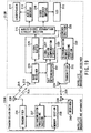
- FIG. 8 is a block diagram showing the arrangement of the geostationary satellite SAT according to this embodiment.
- the CDM broadcasting signal transmitted from each of the ground broadcasting stations BC1, BC2, and BC3 is received by a reception antenna 1111 and amplified by a low-noise amplifier 1112.
- the received CDM broadcasting signal is frequency-converted from the Ku band to the S band by a frequency conversion circuit 1113, amplified to a predetermined transmission power level by a transmission power amplifier 1114, and transmitted from an S-band transmission antenna 1115 to a ground service area.
- the received CDM broadcasting signal output from the low-noise amplifier 1112 is input to a reception circuit 1121, frequency-converted into, e.g., an IF signal, and then distributed to correlators 1131 to 113k.
- the number of correlators 1131 to 113k corresponds to a total number k of channels to be multiplexed/transmitted by each of the ground broadcasting stations BC1 and BC2.
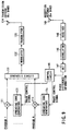
- FIG. 9 is a block diagram showing the arrangement of the transmission section.
- the same reference numerals as in FIG. 2 denote the same parts in FIG. 9.
- the CDM phase difference control signal sent from the geostationary satellite SAT through the Ku-band downlink transmission channel is received by a reception antenna 144, input to a receiver 145, low-noise-amplified, and frequency-converted into an IF signal.
- the spectrum of the received IF signal is despread by a correlator 146 using a spreading code for phase control signal transmission.
- the resultant reception signal is detected by a detector (DET) 147 using a detection method corresponding to, e.g., QPSK.
- the reconstructed phase control signal is input to a control circuit 148.
- the ground broadcasting stations BC1, BC2, and BC3 start transmitting the CDM broadcasting signals at different timings.
- the ground broadcasting station BC2 starts transmitting a CDM broadcasting signal in which channels CH11 to CH1n are multiplexed.
- the ground broadcasting station BC1 starts transmitting a CDM broadcasting signal in which channels CH21 to CH2n are multiplexed.
- the ground broadcasting station BC3 starts transmitting a CDM broadcasting signal in which channels CH31 to CH3n are multiplexed.
- the delay amounts of the transmission timings of the CDM broadcasting signals are set on the basis of the phase control signals sent from the geostationary satellite SAT such that the relative correlation values between the CDM broadcasting signals transmitted from the ground broadcasting stations BC1, BC2, and BC3 become zero on the geostationary satellite SAT, as described previously. For this reason, the CDM broadcasting signals transmitted from the ground broadcasting stations BC1, BC2, and BC3 are received by the geostationary satellite SAT while making the relative phase differences zero, as shown in FIG. 10B.
- the broadcasting receiver receives CDM broadcasting signals with spreading codes synchronized between the ground broadcasting stations BC1, BC2, and BC3.
- spreading code synchronization is established for a CDM broadcasting signal transmitted from one of the ground broadcasting stations
- the broadcasting signal from a desired ground broadcasting station can be separated and reconstructed only by switching the spreading code without newly establishing spreading code synchronization for the CDM broadcasting signals from the remaining ground broadcasting stations. Therefore, when the reception channel is to be switched from the CDM broadcasting signal transmitted from the ground broadcasting station BC1 to the CDM broadcasting signal transmitted from the different ground broadcasting station BC2, switching can be quickly performed at a high response speed.
- the broadcasting receiver may be carried by a high-speed mobile such as an aircraft.
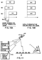
- FIG. 11 is a view showing the schematic arrangement of a satellite broadcasting system according to the seventh to ninth embodiments of the present invention.
- This satellite broadcasting system includes a plurality of ground broadcasting stations BC1 and BC2 and a broadcasting satellite SAT.
- Each of the ground broadcasting stations BC1 and BC2 transmits a program signal prepared and edited by a broadcaster to the broadcasting satellite SAT through a Ka- or Ku-band uplink transmission channel.
- the broadcasting satellite SAT is managed by a satellite tracking control station STCC to keep a predetermined position on the geostationary orbit above the equator.
- a broadcasting signal transmitted from the ground broadcasting station BC1 or BC2 is received by the Ka- or Ku-band antenna 24, demodulated and amplified by a signal processing unit assembled in the satellite main body 21, and converted into a signal in the S-band.
- the converted broadcasting signal is transmitted from the S-band antenna 25 to a service area through an S-band downlink transmission channel.
- a plurality of channels a maximum of 900 channels having a transmission rate of, e.g., 64 to 256 kbps/channel are multiplexed using only code division multiplex or both code division multiplex and time division multiplex or frequency division multiplex.
- MPEG4 Moving Picture Expert Group 4
- the satellite broadcasting receiver of this embodiment includes two antennas 211 and 212, a signal synthesizer 213, a RAKE receiver 214, an audio/video separation circuit section 215, an audio decoder 216, a loudspeaker 217, a video decoder 218, a liquid crystal display (LCD) 219, and a control section 220.
- Each of the two antennas 211 and 212 receives a radio wave arriving through the downlink transmission channel and generates a corresponding electrical signal (transmission signal).
- the antennas 211 and 212 are preferably rod antennas and separated from each other as far as possible.
- the transmission signals obtained by the antennas 211 and 212 are synthesized by the signal synthesizer 213, and the synthesized signal is supplied to the RAKE receiver 214.
- the transmission signal after synthesis by the signal synthesizer 213 is sequentially subjected to known processing such as down-conversion to an IF or a baseband frequency, conversion into a digital signal, spectrum despreading in a plurality of systems, integration in a plurality of systems over one symbol period, synthesis of the integration results of the plurality of systems, deinterleave processing, Viterbi decoding, or error correction decoding, thereby obtaining reception data.
- the reception data obtained by the RAKE receiver 214 is supplied to the audio/video separation circuit section 215 and separated into audio data and video data.
- the audio data is decoded and converted into analog data by the audio decoder 216.
- the audio data is converted into an audio signal and supplied to the loudspeaker 217, so the audio signal is amplified and output from the loudspeaker 217.
- the video data is decoded by the video decoder 218 using, e.g., MPEG4 and supplied to the liquid crystal display 219, so a corresponding image is displayed on the liquid crystal display 219.
- Tuning control for the RAKE receiver 214 and separation control for the audio/video separation circuit section 215 are performed by the control section 220 on the basis of a predetermined control program.
- the antennas 211 and 212 are respectively set near the left corner on the front side and near the right corner on the rear side of a mobile 221 (an automobile in FIG. 14). Since the automobile has an almost rectangular shape when viewed from the upper side, the antennas 211 and 212 are set near diagonal points of the rectangle, respectively.
- the antennas 211 and 212 are offset from each other in the moving direction of the mobile 221 (direction indicated by an arrow A in FIG. 14) and in a direction perpendicular to the moving direction (direction indicated by an arrow B in FIG. 14).
- radio waves from the broadcasting satellite SAT can be received by both the antennas 211 and 212, as shown in FIG. 15A.
- a transmission signal is obtained by each of the antennas 211 and 212, though the two transmission signals may have a phase difference.
- the transmission signals obtained by the antennas 211 and 212 are synthesized by the signal synthesizer 213 and the synthesized signal is supplied to the RAKE receiver 214, the transmission signals obtained by the antennas 211 and 212 are used, in the RAKE receiver 214, for RAKE reception as different transmission signals arriving through different paths, i.e., used for reception at high S/N ratio using the path diversity effect. That is, the signal synthesizer 213 performs not processing of phase-matching the transmission signals obtained by the antennas 211 and 212 but simple synthesis.
- the radio wave which is to reach the antenna 212 is not shielded by the obstacle 222. Since the antenna 212 can receive the radio wave, the reception operation is continuously performed.
- the mobile 221 in the state shown in FIG. 15B further moves in the moving direction shown in FIG. 15B, and the radio wave which is to reach the antenna 212 is shielded by the obstacle 222 to disable radio wave reception by the antenna 212, as shown in FIG. 15C.
- the radio wave which is to reach the antenna 211 is not influenced by the obstacle 222 even when the radio wave which is to reach the antenna 212 is shielded by the obstacle 222. Therefore, as shown in FIG. 15C, the antenna 211 can receive the radio wave, and the reception operation is continuously performed.
- the hit time can be shortened because the time when both the antenna 211 and the antenna 212 cannot receive the radio waves is shortened.
- the satellite broadcasting receiver of this embodiment can be modified by inserting low-noise amplifiers 223 and 224 between the antennas 211 and 212 and the signal synthesizer 213, as shown in FIG. 17, such that the transmission signals can be low-noise-amplified and then synthesized by the signal synthesizer 213.
- a space diversity system for performing reception using a plurality of antennas, as in this embodiment, is known.
- the known space diversity system aims to reduce the influence of fading due to multipath transmission and is unnecessary for the system of this embodiment using multipath transmission.
- the arrangement as a characteristic feature of this embodiment may appear to be similar to the known space diversity system.
- this embodiment allows reception at a high S/N ratio by positively using the multipath signal, so the influence of fading due to multipath transmission is not reduced at all. This means that the arrangement of this embodiment is achieved on the basis of a technical concept different from that of the space diversity system.
- FIG. 18 is a view showing the arrangement of a satellite broadcasting receiver according to the eighth embodiment of the present invention.
- the same reference numerals as in FIG. 13 denote the same parts in FIG. 18, and a detailed description thereof will be omitted.
- This satellite broadcasting receiver is used in the satellite broadcasting system shown in FIG. 11.
- the satellite broadcasting receiver of this embodiment includes an antenna 211, a RAKE receiver 214, an audio/video separation circuit section 215, an audio decoder 216, a loudspeaker 217, a video decoder 218, a liquid crystal display 219, a control section 220, a signal buffer 225, a hit determinator 226, and a signal lost portion compensation circuit 227.
- the signal buffer 225 stores and holds reception data obtained by the RAKE receiver 214 for a predetermined time and then supplies it to the audio/video separation circuit section 215.
- the signal buffer 225 also serves as a work field for reception data processing by the signal lost portion compensation circuit 227.
- the hit determinator 226 monitors the operation condition (e.g., the output condition of reception data) of the RAKE receiver 214 and detects a hit. Upon detecting a hit, the hit determinator 226 notifies the signal lost portion compensation circuit 227 of it.
- the operation condition e.g., the output condition of reception data
- the signal lost portion compensation circuit 227 performs processing of compensating the reception data (lost portion) when the hit determinator 226 detects a hit.
- the hit determinator 226 detects a hit and notifies the signal lost portion compensation circuit 227 of it.
- the signal lost portion compensation circuit 227 generates compensation data for the lost portion by, e.g., copying or estimating the data on the basis of predetermined data (e.g., data of a portion having a high correlation with the lost portion) around the lost portion in the reception data of the normal portion, which is stored and held by the signal buffer 225.
- the signal lost portion compensation circuit 227 writes the generated compensation data in the signal buffer 225 to compensate for the lost portion.
- the lost portion of the reception data due to the hit is compensated for on the basis of the reception data around the normally received portion, so reception data without any lost portion is generated.
- this arrangement degradation in reception quality can be minimized.
- FIG. 19 is a view showing the arrangement of a satellite broadcasting system according to the ninth embodiment of the present invention.
- the same reference numerals as in FIGS. 13 and 18 denote the same parts in FIG. 19, and a detailed description thereof will be omitted.
- FIG. 19 shows the arrangements of one of satellite broadcasting receivers 2100 carried by mobile stations MS in FIG. 11 and one of satellite broadcasting apparatuses 2200 set in broadcasting stations BC in FIG. 11.
- the satellite broadcasting receiver 2100 of this embodiment includes an antenna 211, an audio/video separation circuit section 215, an audio decoder 216, a loudspeaker 217, a video decoder 218, a liquid crystal display 219, a control section 220, a RAKE receiver 228, a signal buffer 229, a signal lost portion compensation circuit 230, a hit determinator 231, a retransmission request processing section 232, a transmitter 233, and an antenna 234.
- a transmission signal obtained by the antenna 211 is subjected, in the RAKE receiver 228, to the same reception processing as that in the RAKE receiver 214 of the seventh embodiment to obtain reception data.
- the RAKE receiver 228 extracts reception data associated with an arbitrary one of broadcasting channels Bch, and parallelly, extracts reception data associated with a predetermined retransmission channel Rch.
- the reception data associated with the arbitrary one of the broadcasting channels Bch is supplied to the signal buffer 229.
- the reception data associated with the retransmission channel Rch is supplied to the signal lost portion compensation circuit 230.
- the signal lost portion compensation circuit 230 performs processing of compensating the reception data (lost portion) using the reception data associated with the retransmission channel Rch when the hit determinator 231 detects a hit.
- the hit determinator 231 monitors the operation condition (e.g., the output condition of the reception data associated with the broadcasting channel Bch) of the RAKE receiver 228 and detects a hit. Upon detecting a hit, the hit determinator 231 notifies the signal lost portion compensation circuit 230 and the retransmission request processing section 232 of it.
- the operation condition e.g., the output condition of the reception data associated with the broadcasting channel Bch
- the retransmission request processing section 232 When the hit determinator 231 detects a hit, the retransmission request processing section 232 generates retransmission request data for requesting retransmission of the lost portion.
- the retransmission request data generated by the retransmission request processing section 232 is converted into a predetermined transmission signal to be radio-transmitted by the transmitter 233, and then, sent from the antenna 234 to the satellite broadcasting apparatus 2200 through a request channel Dch.
- the satellite broadcasting apparatus 2200 of this embodiment includes a transmitter 235, a memory section 236, a retransmission processing section 237, antennas 238 and 239, and a receiver 240.
- transmission data generated by a transmission data generation section (not shown) or the like is supplied to the transmitter 235 and simultaneously supplied to the memory section 236 and stored and held as transmission data which has already been transmitted.
- the mobile carrying the satellite broadcasting receiver 2100 of this embodiment moves, and an obstacle enters between the broadcasting satellite SAT and the antenna 211.
- the radio wave sent from the broadcasting satellite SAT is shielded by the obstacle and prevented from reaching the antenna 211.
- no transmission signal is supplied to the RAKE receiver 228 anymore, and the reception data output from the RAKE receiver 228 indicates no-signal state.
- the retransmission processing section 237 Upon receiving the retransmission request data, the retransmission processing section 237 extracts the transmission data of the portion requested by the retransmission request data from the memory section 236 and generates retransmission data containing the transmission data.
- the retransmission data reaches the signal lost portion compensation circuit 230 through the transmitter 235, the antenna 238, the retransmission channel Rch, the antenna 211, and the RAKE receiver 228.
- the signal lost portion compensation circuit 230 writes the retransmission data in the signal buffer 229 to compensate for the lost portion.
- the satellite broadcasting apparatus 2200 retransmits the transmission data of the lost portion generated in the reception data due to the hit, in response to the request from the satellite broadcasting receiver 2100.
- the satellite broadcasting receiver 2100 compensates for the lost portion using the retransmission data, thereby generating reception data without any lost portion. With this arrangement, degradation in reception quality can be minimized.
- spread spectrum modulation is used as modulation for multipath transmission.
- the present invention can also be applied to a radio communication apparatus used in a system using another modulation scheme such as multicarrier modulation used in OFDM (Orthogonal Frequency Division Multiplex).
- the seventh embodiment can also be applied when three or more antennas are used.
- the antenna 211 and the antenna 212 are respectively set near the left corner on the front side and near the right corner on the rear side of the mobile 221.
- the arrangement is not limited to this.
- an automobile is exemplified as the mobile 221.
- the radio receiver of the present invention can also be carried by another mobile such as a train.
- the antenna 211 and the antenna 212 are set at diagonal positions of each car.
- the antennas may be set at the head of the first car and at the end of the last car.
- the eighth or ninth embodiment can incorporate the arrangement of the antennas 211 and 212 and the signal synthesizer 213 in the seventh embodiment.
- a reception means performs predetermined multipath reception processing for a synthesis signal obtained by synthesizing, by a signal synthesis means, signals obtained by a plurality of antennas spaced apart from each other.
- transmission data demodulated from the radio-transmitted transmission signal by a reception means is stored in a storage means at least for a predetermined time.
- a hit in the transmission signal received by the reception means is monitored by a hit detection means.
- Transmission data corresponding to a transmission signal portion where a hit is detected is compensated by a compensation means on the basis of the transmission data stored in the storage means or using transmission data demodulated from a transmission signal retransmitted by a retransmission means in the radio broadcasting apparatus in response to a retransmission request sent by a retransmission request means.
- FIG. 20 is a schematic view showing a satellite broadcasting system having a gap filler function according to the 10th embodiment of the present invention.
- This satellite broadcasting system includes a plurality of ground broadcasting stations (VSAT) BC1 and BC2 or feeder link stations, a geostationary satellite SAT1, and a satellite tracking control station STCC.
- VSAT ground broadcasting stations
- Each of the ground broadcasting stations (VSAT) BC1 and BC2 or feeder link stations transmits program information prepared and edited by a broadcaster to the geostationary satellite SAT1 through an uplink transmission channel in the Ka band (26.5 to 40 GHz) or the Ku band (12.5 to 18 GHz).
- the geostationary satellite SAT1 has a Ka-band or Ku-band antenna having a diameter of 2.5-m class and an S-band (e.g., 2.6 GHz) antenna having a diameter of 15-m class.
- a broadcasting signal multiplexed and transmitted from one of the broadcasting stations (VSAT) BC1 and BC2 or the feeder link stations is received and amplified by the Ka- or Ku-band antenna and then converted into a signal for the S band.
- the converted broadcasting signal is transmitted from the S-band antenna to a service area through a downlink transmission channel in the S band.
- the uplink transmission antenna carried by the geostationary satellite SAT1 may have a diameter smaller than 2.5-m class.
- the S-band antenna may also have a diameter of not 15-m class but 8-m class.
- the satellite tracking control station STCC monitors and controls the operation state of the geostationary satellite SAT1.
- a gap filler apparatus GFa is set on, e.g., the rooftop of a high-rise building.
- the gap filler apparatus GFa receives the broadcasting signal from the geostationary satellite SAT1, amplifies it, and then retransmits the received broadcasting signal to an area behind a building or the like where the broadcasting signal from the geostationary satellite SAT1 cannot be received while holding the same frequency.
- the gap filler apparatus GFa has the following arrangement.
- FIG. 21 is a block diagram showing the arrangement of the gap filler apparatus GFa.
- a broadcasting signal transmitted from the geostationary satellite SAT1 is received by a reception antenna 311 and input to an signal synthesizer 213. After only a predetermined transmission band is selected by the input filter 312, the signal is amplified by a low-noise amplifier 313.
- the amplified broadcasting signal is amplified by a power amplifier 314, limited to a predetermined transmission band by an output filter 315, and then transmitted from a transmission antenna 316 to a dead area such as an area behind a building where the direct wave from the geostationary satellite SAT1 does not reach.
- a directional antenna is used to limit the broadcasting signal transmission range to the dead area where the direct wave from the geostationary satellite SAT1 cannot be received.
- the broadcasting signal repeated and transmitted from the gap filler apparatus GFa is set at the same frequency as that of the broadcasting signal sent from the geostationary satellite SAT1. For this reason, the broadcasting receiver MS behind a building can receive the broadcasting signal from the gap filler apparatus GFa without using any special receiver as far as it has a receiver for receiving the broadcasting signal from the geostationary satellite SAT1.
- the gap filler apparatus GFa transmits the broadcasting signal to the dead area behind a building while limiting the broadcasting range by using the directional antenna. Even when the signal transmitted from the gap filler apparatus GFa is set at the same frequency as that of the signal sent from the geostationary satellite SAT1, the transmission signal from the gap filler apparatus GFa is prevented from interfering with the signal from the geostationary satellite SAT1 around the dead area behind a building. Thus, the broadcasting receiver MS can receive the broadcasting signal at a high quality in any area.
- a gap filler apparatus GFb is set at, e.g., a large intersection where the broadcasting signal from the geostationary satellite SAT1 can be directly received.
- a post 345 is planted on a paved street, and the gap filler apparatus GFb is fixed on the post 345.
- the gap filler apparatus GFb may be set on the existing post without providing the dedicated post 345.
- a gap filler apparatus GFd may be set on a pylon or the like, as shown in FIG. 25, and a broadcasting signal may be repeated and transmitted from the gap filler apparatus GFd using a non-directional antenna. With this arrangement, a wide, circular dead area can be covered.
- a plurality of channel signals to be transmitted from a ground broadcasting station to a satellite are multiplexed by CDM (Code Division Multiplex).
- CDM Code Division Multiplex
- a gap filler apparatus amplifies the multiplexed CDM broadcasting signal arriving via the satellite, and repeats and transmits it to a gap area behind a building or the like.
- the gap filler apparatus receives the CDM-multiplexed broadcasting signal transmitted from the geostationary satellite, amplifies the reception signal to the transmission power level for gap filler, and transmits it to a dead area.
- the audio/video separation circuit 323 separates the reconstructed reception signal into audio data, video data, and additional data such as text data.
- the separated received audio data is input to an audio decoder 324.
- the received video signal is input to a video decoder 326.
- the additional data is input to an additional data decoder 328.
- the audio decoder 324 decodes the received audio data to reconstruct the audio signal, and the audio signal is amplified and output from a loudspeaker 325.
- the video decoder 326 decodes the received video data by, e.g., MPEG4 and supplies the decoded video signal to a liquid crystal display 327 and causes the liquid crystal display 327 to display the video signal.
- the additional data decoder 328 decodes the additional data such as text data and causes the liquid crystal display 327 to display the decoded data together with the video signal.
- FIG. 28 is a block diagram showing the arrangement of the receiver 322.
- the CDM-multiplexed broadcasting signal arriving from the geostationary satellite and the gap filler apparatus is down-converted from the radio frequency into a baseband frequency by a radio circuit 328.
- the received baseband signal is digitized by an analog/digital converter (A/D) 329 at a predetermined sampling period and then input to a search receiver 330 and three digital data demodulators 331, 332, and 333.
- A/D analog/digital converter
- the search receiver 330 receives and demodulates a pilot signal transmitted from the ground broadcasting station BC1 or BC2 and basically has the same arrangement as that of each of the digital data demodulators 331, 332, and 333 to be described below.
- Each of the digital data demodulators 331, 332, and 333 demodulates a broadcasting signal of the CDM-multiplexed broadcasting signal arriving from the geostationary satellite or the CDM-multiplexed broadcasting signal arriving from the gap filler apparatus, which corresponds to the channel designated by the user, by RAKE reception.
- the digital data demodulators 331, 332, and 333 generate unique clocks with reference to the sampling clock of the A/D converter 329 and independently operate on the basis of the unique clocks.
- Each digital data demodulator has an initial capture section, a clock tracking section, and a data demodulation section.
- the data demodulation sections respectively include phase compensation sections 3311, 3321, and 3331, multipliers 3312, 3322, and 3332, PN code generators 3313, 3323, and 3333, and an accumulators 3314, 3324, and 3334.
- the phase compensation sections 3311, 3321, and 3331 perform phase compensation of the reception signal for path diversity.
- the multipliers 3312, 3322, and 3332 multiply the reception signals output from the phase compensation sections 3311, 3321, and 3331 by PN codes corresponding to the designated channel, which are generated from the PN code generators 3313, 3323, and 3333, respectively, to despread the spectra of the reception signals.
- the accumulators 3314, 3324, and 3334 integrate the reception signals despread and output from the multipliers 3312, 3322, and 3332, respectively.
- the integration outputs are input to a symbol synthesizer 334.
- a control section 335 has a microcomputer as a main control section and has, as a control function associated with RAKE reception, a path position detection means and a PN code generation control means.
- the path position detection means detects, from the pilot signal received by the search receiver 32, the path position of the signal arriving from the geostationary satellite SAT and the path position of the signal arriving from the gap filler apparatus.
- the PN code generation control means calculates an optimum PN address value on the basis of the path position detection result and supplies the PN address value to the PN code generators 3313, 3323, and 3333 of the three digital data demodulators 331, 332, and 333. With this operation, the chip phases of the PN codes generated from the PN code generators 3313, 3323, and 3333 are variably controlled.
- the directivity of the signal to be retransmitted from the gap filler apparatus need not be strictly adjusted, so the gap filler apparatus can be easily set.
- two geostationary satellites i.e., a main satellite and a spare satellite
- a main satellite and a spare satellite are spaced apart by a predetermined distance in the same geostationary orbit.
- Identical broadcasting signals are transmitted from these geostationary satellites to a service area in synchronism with each other. This arrangement allows even a broadcasting receiver MS in an area where the broadcasting signal from the main satellite cannot be received to receive the broadcasting signal from the spare satellite.
- FIG. 29 is a schematic view of a satellite broadcasting system according to this embodiment.
- two geostationary satellites SATa and SATb are placed in the geostationary orbit while being spaced apart by a predetermined distance.
- One of the geostationary satellites SATa and SATb functions as a main satellite, and the other functions as a spare satellite.
- the spare satellite does not stand by but transmits the same broadcasting signal as that from the main satellite even while the main satellite is normally functioning.
- the mobile station MS in an area where a broadcasting signal RSa from the main satellite SATa cannot be received because of a building, as shown in FIG. 26, can receive a broadcasting signal RSb from the spare satellite SATb.
- the mobile station MS in an area where the broadcasting signal RSb from the spare satellite SATb cannot be received can receive the broadcasting signal RSa from the main satellite SATa. Therefore, according to this embodiment, the gap area can be eliminated without setting any gap filler apparatus on the ground.
- the gap filler effect is realized by using an existing spare satellite. For this reason, no new satellite need be launched, and the system can be realized at low cost.
- a broadcasting signal transmitted from a ground broadcasting station or a feeder link station is frequency-converted, in a geostationary satellite, into a first broadcasting signal for a broadcasting receiver and a second broadcasting signal for a gap filler apparatus, which have different frequencies, and transmitted.
- the gap filler apparatus receives the second broadcasting signal, converts it into a broadcasting signal having the same frequency as that of the first broadcasting signal, and then repeats and transmits the broadcasting signal to a dead area.
- FIG. 30 is a schematic view of a satellite broadcasting system according to this embodiment.
- FIG. 31 shows the arrangement of a transponder of a geostationary satellite SAT2 of this system.
- FIG. 32 shows the arrangement of a gap filler apparatus.
- One of the broadcasting signals is frequency-converted into an S-band radio frequency signal (frequency fs) by a first frequency converter 384, amplified, by a first power amplifier 386, to a transmission power level necessary for reception by the broadcasting receiver of a fixed station or a mobile station MS, and then transmitted from an S-band transmission antenna 388 to a ground service area as a first downlink broadcasting signal DLa.
- frequency fs radio frequency signal
- the other of the distributed broadcasting signals is frequency-converted into a Ku-band radio frequency signal (frequency fub) by a second frequency converter 388, amplified, by a second power amplifier 387, to a transmission power level necessary for reception by a gap filler apparatus GFe, and then transmitted from a Ku-band transmission antenna 389 as a second downlink broadcasting signal DLb.
- both the second downlink broadcasting signal DLb and the uplink broadcasting signal UL are transmitted in the Ku band, they have different frequencies.
- the frequency fub of the second downlink broadcasting signal DLb is set at 14 GHz
- the frequency fua of the uplink broadcasting signal UL is set at 12 GHz.
- the second broadcasting signal DLb transmitted from the geostationary satellite SAT2 is received by an antenna 391, amplified by a low-noise amplifier 392, and input to a frequency converter 393.
- the frequency converter 393 frequency-converts the received second downlink broadcasting signal into an S-band radio frequency signal (frequency fs), i.e., a radio frequency signal having the same frequency as that of the first downlink broadcasting signal DLa which is transmitted from the geostationary satellite SAT2 for a broadcasting receiver.
- the broadcasting signal frequency-converted into the S band is amplified to a transmission power level corresponding to the size of a gap filler cover area GE by a power amplifier 394, and then transmitted from a transmission antenna 395 to the gap filler cover area GE as a repeated broadcasting signal DLg.
- a second broadcasting signal having the same contents as those of an uplink broadcasting signal transmitted from a ground broadcasting station to a geostationary satellite is transmitted to a gap filler apparatus through a ground network.
- the gap filler apparatus On the basis of the second broadcasting signal transmitted through the ground network, the gap filler apparatus generates a repeated broadcasting signal which is the same as a downlink broadcasting signal transmitted from the geostationary satellite to a broadcasting receiver, and transmits the repeated broadcasting signal to a dead area.
- FIG. 33 is a block diagram showing the arrangement.
- a ground broadcasting station (not shown) generates a second broadcasting signal having the same contents as those of an uplink broadcasting signal transmitted from the self station to a geostationary satellite and a signal format for cable transmission, and transmits the second broadcasting signal to a gap filler apparatus GFf through a ground public network NW such as an ISDN network.
- NW ground public network
- a signal conversion device 3101 converts the signal format of the second broadcasting signal from the format for cable transmission to a signal format for satellite broadcasting.
- the broadcasting signal for satellite transmission is frequency-converted into an S-band radio frequency signal by a frequency converter 3102, amplified to a transmission power level corresponding to the size of the dead area by a power amplifier 3103, and transmitted from a transmission antenna 3104 to the dead area behind a building or the like as a repeated broadcasting signal.
- the gap filler apparatus cannot be set at a place where the downlink broadcasting signal from the geostationary satellite can be received, the broadcasting signal can be properly broadcasted to the dead area.
- the gap filler apparatus GFf may have not only the circuit for receiving the broadcasting signal through the ground public network NW and generating the repeated broadcasting signal but also a circuit for receiving the downlink broadcasting signal from the geostationary satellite and converting it into the repeated broadcasting signal, as in FIG. 21 or 32.
- One of the broadcasting signals generated by the above circuits may be selected in accordance with the set condition of the gap filler apparatus and transmitted to the dead area.
- a gap filler apparatus has a function of generating monitor information representing the operation state of the self apparatus and transmitting the monitor information to a monitor center, and the monitor center monitors the operation state of the gap filler apparatus on the basis of the monitor information.
- the monitor center MCa collects pieces of monitor information from a plurality of gap filler apparatuses in a service area by polling and displays or prints the collected monitor information.
- the monitor center MCa also determines on the basis of the contents of monitor information whether the operation state of the gap filler apparatus is normal and displays the determination result.
- each gap filler apparatus GFg can be concentrically managed by the monitor center MCa, so efficient maintenance is allowed.
- the monitor information of a number of gap filler apparatuses can be efficiently collected.
- the monitor center can immediately detect it, so quick restoration is possible.
- FIG. 37 shows the third arrangement example of the system according to this embodiment.
- a gap filler apparatus GFi multiplexes monitor information representing the operation state of the self apparatus to the repeated broadcasting signal and transmits it to the dead area.
- FDM or CDM can be used as a multiplex scheme.
- the present invention is not limited to the above embodiments.
- both the scheme of setting a gap filler apparatus on the ground to cover the dead area and the scheme of using two geostationary satellites to cover the dead area may be simultaneously exploited, thereby covering an area which is not covered with either scheme.
- a dead area behind a building is covered.
- the present invention can also be applied to cover a gap area formed due to another construction such as a pylon or a natural object such as a mountain or a cliff.
- the present invention can also be applied to cover an indoor dead area.
- a compact indoor gap filler apparatus (repeater) is set at a position, e.g., at a window where a downlink broadcasting signal from a satellite can be directly received.
- a repeated broadcasting signal is transmitted indoors from this repeater and received by a receiver.
- the receiver may be connected to the repeater through a coaxial cable or the like, and the received downlink broadcasting signal may be transmitted to the receiver through the coaxial cable.
- the repeater may be set on the rooftop or roof of a building or a house.
- a gap filler apparatus is used.
- a broadcasting signal repeated by a satellite is received by the gap filler apparatus.
- the received broadcasting signal is radio-transmitted to an area where the broadcasting signal from the satellite cannot be received, at the same frequency as that of the broadcasting signal transmitted from the satellite.
- FIG. 38 shows the schematic arrangement of a satellite broadcasting system according to the 17th embodiment of the present invention.
- the satellite broadcasting system includes a transmission station 410 situated on the ground and a geostationary satellite 430 placed in the geostationary orbit above the equator while being attitude-controlled on the basis of an instruction signal from a satellite control station 420.
- FIG. 38 illustrates only one station as the transmission station 410. However, a plurality of stations may be used.
- programs 1 to N are input to multipliers 4101 to 410N, respectively, as shown in FIG. 39.
- Spreading codes corresponding to selection numbers (so-called channel numbers) for selecting the signals on the reception terminals are input from spreading code generators 4111 to 411N to the multipliers 4101 to 410N, so the multipliers 4101 to 410N multiply programs 1 to N by the spreading codes, respectively, and output the results to a synthesizer 412.
- the reception antenna 431 of the geostationary satellite 430 is connected to a reception feeder element 433 to output the received channel signals to the reception feeder element 433.
- the reception feeder element 433 is connected to, e.g., a polarizer 434, so the input channel signals (CH1 to CH8) are frequency-converted and output to the polarizer 434.
- the polarizer 434 is connected to a feeder link receiver 435, so the input channel signals are set to be, e.g., circularly polarized waves and output to the feeder link receiver 435.
- the first power amplifier 437a is connected to a right-circular polarizer 438a, so the input channel signals (CH1, CH3, CH5, CH7, and CH8) are power-amplified and output to the right-circular polarizer 438a.
- the right-circular polarizer 438a is connected to a transmission feeder element 439, so the input channel signals (CH1, CH3, CH5, CH7, and CH8) are converted into right-circularly polarized waves and output to the transmission feeder element 439.
- the second power amplifier 437b is connected to a left-circular polarizer 428b, so the input channel signals (CH2, CH4, and CH6) are power-amplified and output to the right-circular polarizer 438b.
- the right-circular polarizer 438b is connected to the transmission feeder element 439, so the input channel signals (CH2, CH4, and CH6) are converted into left-circularly polarized waves and output to the transmission feeder element 439.
- the transmission feeder element 439 is connected to the transmission antenna 432 to transmit the input channel signals (CH1, CH3, CH5, CH7, and CH8) and channel signals (CH2, CH4, and CH6) to a predetermined service area through the downlink transmission channel.
- the reception terminal 450 for receiving the channel signals (CH1 to CH8) from the geostationary satellite 430 has a reception antenna 451 corresponding to the transmission antenna 432 of the geostationary satellite 430, as shown in FIG. 41.
- the received channel signals (CH1 to CH8) are output to a reception feeder element 452.
- the reception feeder element 452 is connected to a right-circular polarizer 453a and a left-circular polarizer 453b.
- the output terminals of the right-circular polarizer 453a and the left-circular polarizer 453b are connected to a receiver 455 through a switch 454.
- a switching operation device (not shown) is connected to the switch 454.
- a switching signal is input.
- the switch 454 selects one of the right-circular polarizer 453a and the left-circular polarizer 453b in accordance with the switching signal to output the channel signals (CH1, CH3, CH5, CH7, and CH8) input to the right-circular polarizer 453a or the channel signals (CH2, CH4, and CH6) input to the left-circular polarizer 453b to the receiver 455.
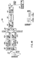
- the receiver 455 has a radio circuit 455a corresponding to the switch 454.
- the radio circuit 455a is connected to a despread circuit 455c through a demodulator 455b.
- the radio circuit 455a frequency-converts the channel signals and outputs them to the demodulator 455b.
- the demodulator 455b demodulates the input channel signals (CH1, CH3, CH5, CH7, and CH8) or channel signals (CH2, CH4, and CH6) and outputs them to the despread circuit 455c.
- the despread circuit 455c is connected to a control circuit 455d for selecting a channel, so the input channel signals (CH1, CH3, CH5, CH7, and CH8) or channel signals (CH2, CH4, and CH6) are subjected to despreading processing, separated on the basis of a channel set signal input to the control circuit 455d, and output to, e.g., a display section (not shown) on the output side.
- the channel set signal is set by the user by switching, e.g., a channel set operation device (not shown).
- a plurality of channel signals having different central frequencies are transmitted in the Ku band from the transmission station 410 to the geostationary satellite 430, classified in units of central frequencies in the geostationary satellite 430, converted into right- or left-circularly polarized waves, and transmitted to the service area as S-band channel signals.
- S-band channel signals By selecting a channel on the reception terminal 450, a desired channel signal is received.
- the signal processing section of the geostationary satellite 430 is divided into a right-circularly polarized wave system and a left-circularly polarized wave system, i.e., constructed using a plurality of signal processing systems with low power efficiency. Since the number of channels can be increased using the signal processing systems with low power efficiency, the arrangement can easily meet the requirement for increasing the number of channels.
- the channel signals (CH1 to CH8) are separated into right-circularly polarized wave signals and left-circularly polarized wave signals and transmitted. Only signals of waves circularly polarized in the same direction act as signal interference sources.
- the interference noise power can be reduced relative to the number of channels. From this viewpoint as well, the number of channels can be made as large as possible.
- the antenna axial ratio of the geostationary satellite 430 to the reception terminal is about 2 dB/3 dB, isolation of 10 dB or more can be ensured to the reversely polarized waves.
- the interference noise power can be reduced by 55%, as compared to use of only one polarized wave.
- the channel capacity can be set to be larger by about 1.8 times.
- the channel signals are circularly polarized to right- or left-circularly polarized waves.
- the channel signals can be linearly polarized to vertically polarized waves or horizontally polarized waves. With this arrangement, almost the same effect as described above can be expected.
- a satellite broadcasting system capable of easily increasing the number of channels and a reception terminal therefor can be provided.
- FIG. 43 shows the schematic arrangement of a satellite broadcasting system according to the 18th embodiment of the present invention.
- This satellite broadcasting system includes a plurality of broadcasting stations BC1 and BC2 (including feeder link stations), a geostationary satellite SAT, and a satellite tracking control station STCC.
- Each of the broadcasting stations BC1 and BC2 transmits program information prepared and edited by a broadcaster to the geostationary satellite SAT through an uplink transmission channel in the Ka band (26.5 to 40 GHz) or Ku band (12.5 to 18 GHz).
- the geostationary satellite SAT is managed by the satellite tracking control station STCC to keep a predetermined position on the geostationary orbit above the equator.
- a fixed station set e.g., in an office or at home or a mobile station MS such as an automobile-carried-type receiver or a portable terminal device receives the broadcasting signal transmitted from the geostationary satellite SAT.
- an "extended antenna structure” in Japanese Patent Application No. 1-245707 an "extended antenna” in Japanese Patent Application No. 1-195704, an "antenna reflecting mirror” in Japanese Patent Application No. 63-242004, or an "extended annular body” in Japanese Patent Application No. 2-261204 can be used.
- the service area can be divided into a plurality of areas, and transmission beams can be independently formed.
- FIG. 45 shows a beam arrangement when the service area is divided into four areas.
- #1 to #4 represent reception areas covered by different transmission beams.
- reference numeral 521 denotes a case.
- the case 521 has a rod antenna 522 for receiving an S-band satellite broadcasting wave, an operation button 523 for performing receiving or tuning, a liquid crystal display 524 for displaying the received video signal, and a pair of loudspeakers (L and R) 525 for amplifying the received audio signal.
- a satellite broadcasting signal from the geostationary satellite SAT which is captured by the rod antenna 522, is tuned to and detected by a receiver 526 and supplied to an audio/video separation circuit section 527.
- the audio/video separation circuit section 527 separates the reception signal into audio data and video data.
- the audio data is supplied to an audio decoder 528, and the video data is supplied to a video decoder 529.
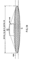
- the rod antenna 522 generally has directivity in all-around directions, as shown in FIG. 48A. In Japan, even a satellite broadcasting wave from a direction of about 45° can be received at a sufficient gain. When an antenna AT whose reception beam pattern has a tilt angle of about 30° to 60° is used, as shown in FIG. 48B, the broadcasting wave from the satellite SAT can be received at almost the maximum gain.
- an automobile-carried-type antenna e.g., can always receive the broadcasting wave from the satellite SAT at the maximum gain even when the automobile has a tilt.
- the audio decoder 528 decodes the received audio data to reconstruct the audio signal.
- the reconstructed audio signal is amplified and output from the loudspeakers 525.
- the video decoder 529 decodes the received video data by, e.g., MPEG4 to reconstruct the video signal.
- the video signal is displayed on the liquid crystal display 524.
- Tuning control of the receiver 526 and separation control of the audio/video separation circuit section 527 are performed by a control CPU circuit section 530 on the basis of a predetermined control program.
- the broadcasting signals transmitted from the plurality of broadcasting stations BC1 and BC2 are sent to the geostationary satellite SAT through the Ka- or Ku-band uplink transmission channel, transmitted from the geostationary satellite SAT to the service area through the S-band downlink transmission channel, and received by the fixed station and the mobile stations MS in the service area.
- a portable receiver has been exemplified.
- An indoor or automobile-carried-type receiver can also be realized by the same circuit arrangement.
- a rod antenna or a planar antenna having non-directional characteristics in at least all-around directions is used. In this case, since the receiver itself need not be directed to the arrival direction of the satellite broadcasting wave, handling of the receiver is greatly facilitated.
- FIGS. 50A and 50B show an example of a broadcasting screen of this system.
- the number of horizontal pixels ⁇ the number of vertical lines of an image is set at 176 ⁇ 144 or 352 ⁇ 288, as shown in FIG. 50A
- the frame frequency per second is set at 15, as shown in FIG. 50B
- the transmission rate is set at about 64 to 256 kbps.
Abstract
Description
- National broadcasting and local broadcasting can be selected.
- Even a handheld reception terminal (with mobility) can sufficiently receive the broadcasting signal.
- A transmission station can be realized with simple equipment and have an interactive function.
- By increasing not only the image quality but also the number of channels, information services can be provided using dedicated channels. For example, various auctions, lectures of private schools or preparatory schools, music programs with CD quality, news, weather forecasts, stock information, leisure information, religious information, local programs, private broadcasting, real estate/housing information, bargain information, TV shopping, various hobbies, data broadcasting, and the like can be realized.
Claims (59)
- A satellite broadcasting system for transmitting a plurality of broadcasting signals of a plurality of channels from a ground broadcasting station (BC1 or BC2), repeating the broadcasting signals with a geostationary satellite (SAT), and broadcasting the broadcasting signals to a broadcasting receiver (MS) in a predetermined service area on the ground,said ground broadcasting station (BC1 or BC2) comprising multiplex means (111-11n, 121-12n, 131) for spreading spectra of the broadcasting signals using different spreading codes in units of channels and synthesizing the broadcasting channels to code-division-multiplex the broadcasting signals of the plurality of channels, and transmitting the broadcasting signals; and transmission synchronization means (140) for setting a phase relationship of the spreading codes between the broadcasting signals of the channels code-division-multiplexed by said multiplex means in a predetermined synchronization state.
- A satellite broadcasting system for transmitting a plurality of broadcasting signals of a plurality of channels from a ground broadcasting station (BC1 or BC2), repeating the broadcasting signals with a geostationary satellite (SAT), and broadcasting the broadcasting signals to a broadcasting receiver (MS) in a predetermined service area on the ground,said ground broadcasting station (BC1 or BC2) comprising multiplex means (111-11n, 121-12n, 131) for spreading spectra of the broadcasting signals using different spreading codes in units of channels and synthesizing the broadcasting channels to code-division-multiplex the broadcasting signals of the plurality of channels, and transmitting the broadcasting signals; andsaid geostationary satellite comprising phase difference detection means (161-16k, 180) for receiving the code-division-multiplexed broadcasting signals transmitted from the ground broadcasting station and detecting a phase difference of the spreading codes between the channels of the code-division-multiplexed broadcasting signals, and transmission synchronization means (180, 171-17k) for setting a phase relationship of the spreading codes between the channels of the received code-division-multiplexed broadcasting signals in a predetermined synchronization state on the basis of a detection result from said phase difference detection means and transmitting the broadcasting signals to the predetermined service area.
- A satellite broadcasting system for transmitting a plurality of broadcasting signals of a plurality of channels from a ground broadcasting station (BC1 or BC2), repeating the broadcasting signals with a geostationary satellite (SAT), and broadcasting the broadcasting signals to a broadcasting receiver (MS) in a predetermined service area on the ground,said ground broadcasting station (BC1 or BC2) comprising multiplex means (111-11n, 121-12n, 135) for spreading spectra of the broadcasting signals using different spreading codes in units of channels and synthesizing the broadcasting channels to code-division-multiplex the broadcasting signals of the plurality of channels, and transmitting the broadcasting signals, and phase difference information transmission means (141) for transmitting information representing a phase difference of the spreading codes between the broadcasting signals of the channels, which are multiplexed by said multiplex means, to notify the geostationary satellite of the information; andsaid geostationary satellite (SAT) comprising phase difference information reception means (157, 181) for receiving the information representing the phase difference, and transmission synchronization means (181, 171-17k) for setting a phase relationship of the spreading codes between the channels of the received code-division-multiplexed broadcasting signals in a predetermined synchronization state on the basis of the information representing the phase difference, which is received by said phase difference information reception means, and transmitting the broadcasting signals to the predetermined service area.
- A satellite broadcasting system for transmitting a plurality of broadcasting signals of a plurality of channels from a ground broadcasting station (BC1 or BC2), repeating the broadcasting signals with a geostationary satellite (SAT), and broadcasting the broadcasting signals to a broadcasting receiver (MS) in a predetermined service area on the ground,said ground broadcasting station (BC1 or BC2) comprising multiplex means (111-11n, 121-12n, 135) for spreading spectra of the broadcasting signals using different spreading codes in units of channels and synthesizing the broadcasting channels to code-division-multiplex the broadcasting signals of the plurality of channels, and transmitting the broadcasting signals, and phase difference information transmission means (141) for transmitting information representing a phase difference of the spreading codes between the broadcasting signals of the channels, which are multiplexed by said multiplex means, to notify the broadcasting receiver of the information; andthe broadcasting receiver comprising phase difference information reception means (194, 196, 190) for receiving the information representing the phase difference, and reception synchronization means (190) for establishing spreading code synchronization for the channels of the code-division-multiplexed broadcasting signals received via the geostationary satellite, on the basis of the information representing the phase difference, which is received by said phase difference information reception means.
- A satellite broadcasting system for transmitting a plurality of broadcasting signals of a plurality of channels from a ground broadcasting station (BC1 or BC2), repeating the broadcasting signals with a geostationary satellite (SAT), and broadcasting the broadcasting signals to a broadcasting receiver (MS) in a predetermined service area on the ground,said ground broadcasting station (BC1 or BC2) comprising multiplex means (111-11n, 121-12n, 131) for spreading spectra of the broadcasting signals using different spreading codes in units of channels and synthesizing the broadcasting channels to code-division-multiplex the broadcasting signals of the plurality of channels, and transmitting the broadcasting signals;said geostationary satellite (SAT) comprising phase difference detection means (161-16k, 182) for receiving the code-division-multiplexed broadcasting signals transmitted from the ground broadcasting station and detecting a phase difference of the spreading codes between the channels of the code-division-multiplexed broadcasting signals, and phase difference information transmission means (182, 158) for transmitting information representing the phase difference of the spreading codes between the broadcasting signals of the channels, which is detected by said phase difference detection means, to notify the broadcasting receiver of the information; andsaid broadcasting receiver (MS) comprising phase difference information reception means (194, 196, 190) for receiving the information representing the phase difference, and reception synchronization means (190) for establishing spreading code synchronization for the channels of the code-division-multiplexed broadcasting signals received via the geostationary satellite, on the basis of the information representing the phase difference, which is received by said phase difference information reception means.
- A satellite broadcasting system for transmitting a broadcasting signal of at least one channel from each of a plurality of ground broadcasting stations (BC1, BC2), repeating the broadcasting signals with a geostationary satellite (SAT), and broadcasting the broadcasting signals to a broadcasting receiver (MS) in a predetermined service area on the ground,each of said plurality of ground broadcasting stations (BC1, BC2) comprising transmission means (111-11n, 121-12n, 131) for spreading spectra of broadcasting signals to be transmitted from a self station using different spreading codes in units of channels and transmitting the broadcasting signals; andsaid geostationary satellite (SAT) comprising phase difference detection means (161-16k, 182) for receiving the broadcasting signals of the channels, which are transmitted from the plurality of ground broadcasting stations, and detecting a phase difference of the spreading codes between the broadcasting signals of the channels, and repeat transmission synchronization means (182, 158) for setting a phase relationship of the spreading codes between the channels of the broadcasting signals received from the plurality of ground broadcasting stations in a predetermined synchronization state on the basis of a detection result from said phase difference detection means and transmitting the broadcasting signals to the predetermined service area.
- A satellite broadcasting system for transmitting a broadcasting signal of at least one channel from each of a plurality of ground broadcasting stations (BC1, BC2), repeating the broadcasting signals with a geostationary satellite (SAT), and broadcasting the broadcasting signals to a broadcasting receiver (MS) in a predetermined service area on the ground,each of said plurality of ground broadcasting stations (BC1, BC2) comprising transmission means (111-11n, 121-12n, 131) for spreading spectra of broadcasting signals to be transmitted from a self station using different spreading codes in units of channels and transmitting the broadcasting signals, and transmission timing control means (148) for variably controlling a transmission timing of the broadcasting signals to be transmitted by said transmission means in units of channels; andsaid geostationary satellite (SAT) comprising phase difference detection means (1131-113k, 1122) for receiving the broadcasting signals of the channels, which are transmitted from the plurality of ground broadcasting stations, and detecting a phase difference of the spreading codes between the broadcasting signals of the channels, and phase difference information notification means (1141-114k, 1123-1125) for supplying information representing the phase difference detected by said phase difference detection means to each of the ground broadcasting stations as sources, thereby causing said transmission timing control means to variably control the transmission timing such that the phase difference of the spreading codes between the broadcasting signals of the channels transmitted from the ground broadcasting stations is made zero.
- A radio receiver (MS) carried by a mobile (MS) and used in a radio communication system for radio-transmitting a transmission signal modulated by a predetermined modulation scheme for multipath transmission for which both a direct wave and an indirect wave are used, said apparatus (MS) comprising:signal synthesis means (213) for synthesizing signals obtained by a plurality of antennas (211, 212) spaced apart from each other; andreception means (214) for receiving a synthesis signal obtained by said signal synthesis means and performing predetermined multipath reception processing.
- A radio receiver according to claim 8, wherein two of the plurality of antennas (211, 212) are arranged on the mobile while being offset from each other both in a moving direction of the mobile carrying the antennas and in a direction perpendicular to the moving direction.
- A radio receiver according to claim 8, wherein two antennas (211, 212) provided on the mobile while being offset from each other both in a moving direction of the mobile carrying the antennas and in a direction perpendicular to the moving direction are respectively arranged near two points on a contour of the mobile where a linear distance between the two antennas is maximized.
- A radio receiver (MS) used in a radio communication system for radio-transmitting a predetermined transmission signal and carried by a mobile (MS), said apparatus (MS) comprising:reception means (214) for demodulating transmission data from the radio-transmitted transmission signal;storage means (225) for storing the transmission data obtained by said reception means at least for a predetermined period;hit detection means (226) for detecting a hit generated in the transmission signal received by said reception means; andcompensation means (227) for compensating transmission data corresponding to a transmission signal portion where the hit is detected by said hit detection means, on the basis of the transmission data stored in said storage means.
- A radio broadcasting system for radio-broadcasting a predetermined transmission signal from a radio broadcasting apparatus (BC1, BC2) to a radio receiver (MS), said system comprising:reception means (228), arranged in the radio receiver, for demodulating transmission data from the radio-broadcasted transmission signal;delay means (229), arranged in the radio receiver, for delaying the transmission data obtained by said reception means at least for a predetermined period;hit detection means (231), arranged in the radio receiver, for detecting a hit generated in the transmission signal received by said reception means;retransmission request means (232), arranged in the radio receiver, for requesting the radio broadcasting apparatus to retransmit a transmission signal corresponding to a portion where the hit is detected by said hit detection means;retransmission means (237), arranged in the radio broadcasting apparatus, for transmitting the transmission signal corresponding to the requested portion using a predetermined retransmission channel in response to the retransmission request from said retransmission request means; andcompensation means (230), arranged in the radio receiver, for compensating, in the transmission data delayed by said delay means, transmission data corresponding to the transmission signal portion where the hit is detected by said hit detection means, using transmission data demodulated, by said reception means, from the transmission signal transmitted from said retransmission means in response to the request from said retransmission request means and arriving through the retransmission channel.
- A radio receiver (MS) carried by a mobile (MS) and used in a radio broadcasting system for radio-broadcasting a predetermined transmission signal from a radio broadcasting apparatus (BC1, BC2) to the radio receiver (MS), said apparatus (MS) comprising:reception means (228) for demodulating transmission data from the radio-broadcasted transmission signal;delay means (229) for delaying the transmission data obtained by said reception means at least for a predetermined period;hit detection means (231) for detecting a hit generated in the transmission signal received by said reception means;retransmission request means (232) for requesting the radio broadcasting apparatus to retransmit a transmission signal corresponding to a portion where the hit is detected by said hit detection means; andcompensation means (230) for compensating, in the transmission data delayed by said delay means, transmission data corresponding to the transmission signal portion where the hit is detected by said hit detection means, using transmission data demodulated, by said reception means, from the transmission signal transmitted from the radio broadcasting apparatus in response to the request from said retransmission request means and arriving through a predetermined retransmission channel.
- A radio broadcasting apparatus (BC1, BC2) used in a radio broadcasting system for radio-broadcasting a predetermined transmission signal from the radio broadcasting apparatus (BC1, BC2) to aradio receiver (MS), said apparatus (BC1, BC2) comprising:means (240) for receiving a retransmission request from the radio receiver; andretransmission means (237) for transmitting a transmission signal of a requested portion using a predetermined retransmission channel in response to the request.
- A satellite broadcasting system for repeating a broadcasting signal transmitted from a ground broadcasting station (BC1 or BC2) with a satellite (SAT1) and broadcasting the broadcasting signal to a predetermined service area on the ground, comprising:a gap filler apparatus (GFa-GFi) comprising means for receiving the broadcasting signal repeated by the satellite (SAT1), and means for radio-transmitting a signal having the same frequency as that of the broadcasting signal transmitted from the satellite (SAT1), to an area in the service area, where the broadcasting signal from the satellite (SAT1) cannot be received.
- A satellite broadcasting system according to claim 15, wherein said gap filler apparatus (Gfa-GFi) has a directional antenna (316) and the received broadcasting signal with directivity is radio-transmitted from said directional antenna (316) to the area where the broadcasting signal from the satellite (SAT1) cannot be received.
- A satellite broadcasting system according to claim 16, wherein when the satellite (SAT1) is a geostationary satellite placed in a geostationary orbit above the equator, said gap filler apparatus (GFa-GFi) radio-transmits the received broadcasting signal with directivity in east-and-west directions.
- A satellite broadcasting system according to claim 15, wherein:at least one of said ground broadcasting station (BC1 or BC2) and the satellite (SAT1) comprises modulation means for spread-spectrum-modulating the broadcasting signal using a predetermined spreading code and transmitting the broadcasting signal, andsaid gap filler apparatus (GFa-GFi) receives the spread-spectrum-modulated broadcasting signal transmitted from the satellite (SAT1) and radio-transmits the received broadcasting signal to the area in the service area, where the broadcasting signal from the satellite (SAT1) cannot be received.
- A gap filler apparatus (GFa-GFi) used in a satellite broadcasting system for transmitting a broadcasting signal to a predetermined service area on the ground via a satellite (SAT1), said apparatus (GFa-GFi) comprising:a first antenna (311) for receiving the broadcasting signal transmitted from the satellite (SAT1);a radio circuit section (312-315) for at least amplifying the broadcasting signal received by said first antenna (311) and outputting a transmission broadcasting signal having the same frequency as that of the received broadcasting signal; anda second antenna (316) for radio-transmitting the transmission broadcasting signal output from said radio circuit section (312-315) to an area in the service area, where the broadcasting signal from the satellite (SAT1) cannot be received.
- A gap filler apparatus (GFa-GFi) according to claim 19, wherein when the satellite (SAT1) is a geostationary satellite placed in a geostationary orbit above the equator, said second antenna (316) radio-transmits the transmission broadcasting signal with directivity in east-and-west directions.
- A satellite broadcasting system comprising:a first satellite (SATa) placed in a predetermined orbit to transmit a broadcasting signal sent from a ground broadcasting station (BC1 or BC2) to a predetermined service area on the ground; anda second satellite (SATb) placed in the same orbit as that of said first satellite (SATa) while being spaced apart from said first satellite by a predetermined distance to synchronously transmit the same broadcasting signal as that transmitted from said first satellite (SATa) to the service area.
- A satellite broadcasting system according to claim 21, wherein a spare satellite for said first satellite (SATa) is used as said second satellite (SATb).
- A satellite broadcasting system comprising:a satellite (SAT1) for repeating a broadcasting signal transmitted from a ground broadcasting station (BC1 or BC2) and transmitting the broadcasting signal to a predetermined service area on the ground;a plurality of broadcasting receivers (MS) each having a function of receiving and reconstructing the broadcasting signal repeated by said satellite (SAT1) in the service area; anda gap filler apparatus (GFa-GFi) for receiving the broadcasting signal repeated by said satellite (SAT1) and transmitting the received broadcasting signal to an area in the service area, where the broadcasting signal from said satellite (SAT1) cannot be received, whereinsaid satellite (SAT1) comprises conversion means for converting the broadcasting signal transmitted from the ground broadcasting station (BC1 or BC2) into first and second broadcasting signals having different frequencies and radio-transmitting the first and second broadcasting signals, andsaid gap filler apparatus (GFa-GFi) comprises means for receiving the second broadcasting signal transmitted from said satellite (SAT1) and converting the second broadcasting signal into a third broadcasting signal having the same frequency as that of the first broadcasting signal, and means for radio-transmitting the third broadcasting signal to the area in the service area, where the first broadcasting signal from the satellite (SAT1) cannot be received.
- A satellite broadcasting system according to claim 23, wherein said broadcasting receiver (MS) further comprises means for receiving the first broadcasting signal and the third broadcasting signal and synthesizing the first and third broadcasting signals.
- A satellite broadcasting system according to claim 23, wherein said conversion means of said satellite (SAT1) converts the broadcasting signal transmitted from the ground broadcasting station (BC1 or BC2) into the first broadcasting signal in an S band and the second broadcasting signal in a frequency band higher than the S band, transmits the first broadcasting signal as a signal for said broadcasting receiver (MS), and simultaneously transmits the second broadcasting signal as a signal for said gap filler apparatus (GFa-GFi).
- A satellite broadcasting system comprising:a satellite (SAT1) for repeating a broadcasting signal transmitted from a ground broadcasting station (BC1 or BC2) and transmitting the broadcasting signal to a predetermined service area on the ground;a plurality of broadcasting receivers (MS) each having a function of receiving and reconstructing the broadcasting signal repeated by said satellite (SAT1) in the service area; anda gap filler apparatus (GFa-GFi) for receiving the broadcasting signal repeated by said satellite (SAT1) and transmitting the received broadcasting signal to an area in the service area, where the broadcasting signal from said satellite (SAT1) cannot be received, whereinsaid satellite (SAT1) comprises means for repeating a first broadcasting signal transmitted from the ground broadcasting station (BC1 or BC2) and a second broadcasting signal having the same contents as those of the first broadcasting signal, andsaid gap filler apparatus (GFa-GFi) comprises means for receiving the second broadcasting signal transmitted from said satellite (SAT1) and converting the second broadcasting signal into a third broadcasting signal having the same frequency as that of the first broadcasting signal, and means for radio-transmitting the third broadcasting signal to the area in the service area, where the first broadcasting signal from the satellite (SAT1) cannot be received.
- A satellite broadcasting system for repeating a broadcasting signal transmitted from a ground broadcasting station (BC1 or BC2) with a satellite (SAT1) and transmitting the broadcasting signal to a predetermined service area on the ground, comprising:ground network transmission means for transmitting, through a ground network (NM), a second broadcasting signal having the same contents as those of a first broadcasting signal transmitted from the ground broadcasting station (BC1 or BC2) to the satellite (SAT1); anda gap filler apparatus (GFa-GFi) for receiving the second broadcasting signal transmitted by said ground network transmission means, converting the received second broadcasting signal into a third broadcasting signal in the same frequency band as that of the broadcasting signal transmitted from the satellite (SAT1), and radio-transmitting the third broadcasting signal to an area in the service area, where the broadcasting signal from the satellite (SAT1) cannot be received.
- A satellite broadcasting system for repeating a broadcasting signal transmitted from a ground broadcasting station (BC1 or BC2) with a satellite (SAT1) and transmitting the broadcasting signal to a predetermined service area on the ground, said system comprising:another satellite (SAT') for repeating a second broadcasting signal having the same contents as those of a first broadcasting signal transmitted from the ground broadcasting station (BC1 or BC2) to the satellite (SAT1); anda gap filler apparatus (GFa-GFi) for receiving the second broadcasting signal repeated by said other satellite (SAT'), converting the received second broadcasting signal into a third broadcasting signal in the same frequency band as that of the broadcasting signal transmitted from the satellite (SAT1), and radio-transmitting the third broadcasting signal to an area in the service area, where the broadcasting signal from the satellite (SAT1) cannot be received.
- A satellite broadcasting system for repeating a broadcasting signal transmitted from a ground broadcasting station (BC1 or BC2) with a satellite (SAT1) and transmitting the broadcasting signal to a predetermined service area on the ground, said system comprising:ground network transmission means for transmitting, through a ground network (NM), a second broadcasting signal having the same contents as those of a first broadcasting signal transmitted from the ground broadcasting station (BC1 or BC2) to the satellite (SAT1);another satellite (SAT') for repeating a second broadcasting signal having the same contents as those of a first broadcasting signal transmitted from the ground broadcasting station (BC1 or BC2) to the satellite (SAT1); anda gap filler apparatus (GFa-GFi) for selectively receiving one of the second broadcasting signal transmitted by said ground network transmission means and the second broadcasting signal repeated by said other satellite (SAT'), converting the received second broadcasting signal into a third broadcasting signal in the same frequency band as that of the broadcasting signal transmitted from the satellite (SAT1), and radio-transmitting the third broadcasting signal to an area in the service area, where the broadcasting signal from the satellite (SAT1) cannot be received.
- A satellite broadcasting system according to claim 29, wherein said gap filler apparatus (GFa-GFi) comprises switching means (SW) for switching to receive one of the second broadcasting signal transmitted by said ground network transmission means and the second broadcasting signal repeated by said other satellite (SAT').
- A gap filler apparatus (GFa-GFi) used in a satellite broadcasting system for repeating a broadcasting signal transmitted from a ground broadcasting station (BC1 or BC2) with a satellite (SAT1) and transmitting the broadcasting signal to a predetermined service area on the ground, said apparatus (GFa-GFi) comprising:ground network reception means for receiving, from the ground broadcasting station (BC1 or BC2) through a ground network, a second broadcasting signal having the same contents as those of the broadcasting signal transmitted from the ground broadcasting station (BC1 or BC2) to the satellite (SAT1);conversion means for converting the second broadcasting signal received by said ground network reception means into a third broadcasting signal in the same frequency band as that of the broadcasting signal transmitted from the satellite (SAT1); andtransmission means for radio-transmitting the third broadcasting signal obtained by said conversion means to an area in the service area, where the broadcasting signal from the satellite (SAT1) cannot be received.
- A gap filler apparatus (GFa-GFi) used in a satellite broadcasting system for repeating a broadcasting signal transmitted from a ground broadcasting station (BC1 or BC2) with a satellite (SAT1) and transmitting the broadcasting signal to a predetermined service area on the ground, said apparatus (GFa-GFi) comprising:satellite reception means for receiving the broadcasting signal transmitted from the satellite (SAT1);ground network reception means for receiving, through a ground network, a second broadcasting signal having the same contents as those of the broadcasting signal transmitted from the ground broadcasting station (BC1 or BC2) to the satellite (SAT1);conversion means for converting the second broadcasting signal received by said ground network reception means into a third broadcasting signal in the same frequency band as that of the broadcasting signal transmitted from the satellite (SAT1); andselective transmission means for selecting one of the broadcasting signal received by said satellite reception means and the third broadcasting signal obtained by said conversion means and radio-transmitting the selected signal to an area in the service area, where the broadcasting signal from the satellite (SAT1) cannot be received.
- A gap filler apparatus (GFa-GFi) according to claim 32, wherein said selective transmission means determines whether said satellite reception means receives a broadcasting signal of not less than a predetermined level, selects the broadcasting signal received by said satellite reception means and radio-transmits the broadcasting signal to the reception disabled area when it is determined that the broadcasting signal of not less than the predetermined level is received, or radio-transmits the third broadcasting signal obtained by said conversion means to the reception disabled area when it is determined that the broadcasting signal of not less than the predetermined level is not received.
- A satellite broadcasting system for repeating a broadcasting signal with a satellite (SAT1) and broadcasting the broadcasting signal to a predetermined service area on the ground, said system comprising:a gap filler apparatus (GFa-GFi) for receiving the broadcasting signal repeated by the satellite (SAT1) and radio-transmitting the received broadcasting signal to an area in the service area, wherein the broadcasting signal from the satellite (SAT1) cannot be received; anda monitor apparatus (MCa-MCc) connected to said gap filler apparatus (GFa-GFi) through a communication line (NW), whereinsaid gap filler apparatus (GFa-GFi) comprises monitor information transmission means for generating monitor information representing an operation state of a self apparatus and transmitting the monitor information to said monitor apparatus (MCa-MCc) through the communication line (NW), andsaid monitor apparatus (MCa-MCc) comprises means for receiving the monitor information transmitted from said gap filler apparatus (GFa-GFi) through the communication line (NW) and performing predetermined processing of monitoring the operation state of said gap filler apparatus (GFa-GFi) on the basis of the received monitor information.
- A satellite broadcasting system according to claim 34, wherein:said monitor apparatus (MCa-MCc) comprises means for transmitting a monitor information transmission request to said gap filler apparatus (GFa-GFi) through the communication line (NW) regularly or as needed, andsaid monitor information transmission means of said gap filler apparatus (GFa-GFi) comprises means for storing the monitor information, and means for reading the monitor information and transmitting the monitor information to said monitor apparatus (MCa-MCc) every time the transmission request arrives from said monitor apparatus (MCa-MCc).
- A satellite broadcasting system according to claim 34, wherein said monitor information transmission means of said gap filler apparatus (GFa-GFi) comprises means for monitoring the operation state of the self apparatus, and means for, when said means detects an error in the operation state of the self apparatus, transmitting monitor information representing contents of the error to said monitor apparatus (MCa-MCc) through the communication line (NW).
- A satellite broadcasting system according to claim 33, wherein said monitor information transmission means of said gap filler apparatus (GFa-GFi) comprises means for monitoring the operation state of the self apparatus, and means for, when said monitor means detects an error in the operation state of the self apparatus, generating message information and transmitting the message information to a broadcasting receiver (MS) in an area covered by the self apparatus.
- A satellite broadcasting system for repeating a broadcasting signal with a satellite (SAT1) and broadcasting the broadcasting signal to a predetermined service area on the ground, said system comprising:a gap filler apparatus (GFa-GFi) for receiving the broadcasting signal repeated by the satellite (SAT1) and radio-transmitting the received broadcasting signal to an area in the service area, wherein the broadcasting signal from the satellite (SAT1) cannot be received;a monitor receiver (MR) set in the reception disabled area and having a function of receiving the received broadcasting signal transmitted from said gap filler apparatus (GFa-GFi); anda monitor apparatus (MCa-MCc) connected to said monitor receiver (MR) through a communication line (INW), whereinsaid gap filler apparatus (GFa-GFi) comprises means for generating monitor information representing an operation state of a self apparatus, inserting the monitor information into the received broadcasting signal, and radio-transmitting the broadcasting signal,said monitor receiver (MR) comprises means for receiving the received broadcasting signal transmitted from said gap filler apparatus (GFa-GFi) and extracting the monitor information from the received broadcasting signal, means for detecting a reception state of the received broadcasting signal, and means for transmitting the extracted monitor information and detection information of the reception state to said monitor apparatus (MCa-MCc) through the communication line (INW), andsaid monitor apparatus (MCa-MCc) comprises means for receiving the monitor information and the detection information, which are transmitted from said monitor receiver (MR) through the communication line (INW), and performing predetermined processing of monitoring the operation state of said gap filler apparatus (GFa-GFi) on the basis of the received monitor information and detection information.
- A satellite broadcasting system in which a plurality of channel signals having different central frequencies are transmitted from a transmission station (410) to a satellite (430) placed in a geostationary orbit, and the channel signals are transmitted from the satellite (430) to a service area and received by a reception terminal (450),said satellite (430) comprising signal reception means for receiving the plurality of channel signals transmitted from the transmission station (410), classification means for frequency-converting the channel signals received by said reception means and classifying the signals in accordance with frequency positions, polarization setting means for amplifying the channel signals classified by said classification means and then setting, for each channel signal, right circular polarization or left circular polarization in accordance with classification, and signal transmission means for transmitting the channel signals for which polarization is set by said polarization setting means; andsaid reception terminal (450) comprising reception means for receiving the channel signals transmitted from said signal transmission means, polarization processing means for selecting circular polarization corresponding to selected channels of the channel signals received by said reception means, and channel selection means for selecting a desired channel signal from the channel signals for which circular polarization is selected by said polarization processing means.
- A satellite broadcasting system according to claim 39, wherein the channel signals are multiplexed by code division multiplex in units of channels.
- A satellite broadcasting system in which a plurality of channel signals having different central frequencies are transmitted from a transmission station (410) to a satellite (430) placed in a geostationary orbit, and the channel signals are transmitted from the satellite (430) to a service area and received by a reception terminal (450),said satellite (430) comprising signal reception means for receiving the plurality of channel signals transmitted from the transmission station (410), classification means for frequency-converting the channel signals received by said reception means and classifying the signals in accordance with frequency positions, polarization setting means for amplifying the channel signals classified by said classification means and then setting, for each channel signal, vertical polarization or horizontal polarization in accordance with classification, and signal transmission means for transmitting the channel signals for which polarization is set by said polarization setting means; andsaid reception terminal (450) comprising reception means for receiving the channel signals transmitted from said signal transmission means, polarization processing means for selecting linear polarization corresponding to selected channels of the channel signals received by said reception means, and channel selection means for selecting a desired channel signal from the channel signals for which linear polarization is selected by said polarization processing means.
- A satellite broadcasting system according to claim 41, wherein the channel signals are multiplexed by code division multiplex in units of channels.
- A reception terminal (450) comprising:reception means for receiving a plurality of right- or left-circularly polarized channel signals; andchannel selection means for selecting circular polarization corresponding to selected channels for the channel signals received by said reception means and outputting the channel signals.
- A reception terminal (450) according to claim 43, wherein the channel signals are multiplexed by code division multiplex in units of channels.
- A reception terminal (450) comprising:reception means for receiving a plurality of vertically or horizontally polarized channel signals;polarization processing means for selecting linear polarization corresponding to selected channels for the channel signals received by said reception means; andchannel selection means for selecting a desired channel signal from the channel signals for which linear polarization is selected by said polarization processing means.
- A reception terminal (450) according to claim 45, wherein the channel signals are multiplexed by code division multiplex in units of channels.
- A satellite broadcasting system for providing digital broadcasting using a geostationary satellite (SAT) placed in a geostationary orbit above the equator, said system comprising:a reception antenna (513) mounted on the geostationary satellite (SAT) to receive digital signals of a plurality of channels sent to the geostationary satellite (SAT);a signal processing unit mounted on the geostationary satellite (SAT) to signal-convert the digital signals of the plurality of channels received by said reception antenna (513), power-amplify the signals, and output the signals; anda transmission antenna (514) mounted on the geostationary satellite (SAT) and comprising a primary radiator (5142) for radiating the digital channels of the plurality of channels output from said signal processing unit and a reflecting mirror (5141) for radiating a radio wave radiated by said primary radiator (5142) to a specific area to form a transmission beam, said reflecting mirror (5141) having a diameter for obtaining a power strength receivable by a receiver (521-530) for satellite broadcasting in the specific area.
- A satellite broadcasting system according to claim 47, wherein:said transmission antenna (514) comprises multibeam formation means for independently forming transmission beams for areas obtained by dividing the specific area into a plurality of areas, andsaid signal processing unit assigns each of the digital signals of the plurality of channels to an arbitrary one of the transmission beams from said reflection-type transmission antenna (514).
- A satellite broadcasting system according to claim 47, wherein the digital signal to said geostationary satellite (SAT) and the digital signal sent from said geostationary satellite (SAT) to the specific area have different frequency bands.
- A satellite broadcasting system according to claim 47, wherein a communication channel is included in the plurality of channels.
- A satellite broadcasting system according to claim 47, wherein MPEG4 (Moving Picture Expert Group 4) is used to code the digital signals.
- A satellite broadcasting system according to claim 51, wherein the number of horizontal pixels, the number of vertical lines, the number of frames per unit time of the digital signal are smaller than those of a standard television broadcasting signal, respectively.
- A satellite broadcasting system according to claim 47, further comprising a receiver (521-530) for receiving satellite broadcasting by said satellite broadcasting system, which comprises a rod antenna (522) having directivity toward the geostationary satellite (SAT) while said reception antenna (513) of the satellite broadcasting has directivity at least in all-around directions.
- A satellite broadcasting system according to claim 51, further comprising a receiver (521-530) for receiving satellite broadcasting by said satellite broadcasting system, which comprises an MPEG4 decoder (529) for extracting a digital signal compressed and coded by MPEG4 (Moving Picture Expert Group 4) from the received digital signal and decoding the digital signal.
- A satellite broadcasting receiver for receiving digital broadcasting using a geostationary satellite placed in a geostationary orbit above the equator, said apparatus comprising:a microphone (65) for converting speech of a user into an electrical signal;speech recognition means (610b) for recognizing a channel designated by the user from the electrical signal obtained by said microphone (65); andreception means (62) for receiving, from broadcasting signals transmitted from the geostationary satellite, the channel recognized by said speech recognition means (610b).
- A satellite broadcasting receiver according to claim 55, wherein contents of the channel received by said reception means (62) are visually and hierarchically displayed.
- A satellite broadcasting system according to claim 55, further comprising:voiceprint data storage means (69a) for storing voiceprint data of a specific user; andspecific user identification means (610a) for comparing the electrical signal obtained from said microphone (65) with the voiceprint data recorded in said voiceprint data storage means (69a) to identify whether the user is the specific user, and whereinwhen a predetermined channel is to be received, said reception means (62) performs reception only when the user is identified as the specific user by said specific user identification means (610a).
- A satellite broadcasting receiver for receiving digital broadcasting using a geostationary satellite placed in a geostationary orbit above the equator, said apparatus comprising:fatigue state estimation means (610c) for detecting a fatigue state of a driver of a mobile on the basis of a moving state of the mobile carrying said satellite broadcasting receiver; andreception means (62) for receiving, from broadcasting signals transmitted from the geostationary satellite, a channel corresponding to the fatigue state detected by said fatigue state estimation means (610c).
- A satellite broadcasting receiver for receiving digital broadcasting using a geostationary satellite placed in a geostationary orbit above the equator, said apparatus comprising:timepiece means (68) for counting time;view data detection means (610e) for detecting a channel received by said satellite broadcasting receiver and a reception time;an interface (671) connectable to a recording medium (672) on/from which data can be written/read; andview data recording control means (610e) for recording, on said recording medium (672) connected to said interface (671), the reception channel and time detected by said view data detection means (610e) in correspondence with each other.
Applications Claiming Priority (13)
| Application Number | Priority Date | Filing Date | Title |
|---|---|---|---|
| JP17867497 | 1997-07-03 | ||
| JP17867897 | 1997-07-03 | ||
| JP17867697 | 1997-07-03 | ||
| JP17865997 | 1997-07-03 | ||
| JP17867897A JPH10308941A (en) | 1997-03-03 | 1997-07-03 | Satellite broadcast system and satellite broadcast receiver |
| JP17867797 | 1997-07-03 | ||
| JP9178677A JPH1174826A (en) | 1997-06-17 | 1997-07-03 | Radio receiver, radio broadcasting system and radio broadcasting device |
| JP9178674A JPH1127592A (en) | 1997-07-03 | 1997-07-03 | Satellite broadcast receiver |
| JP17867697A JP3505354B2 (en) | 1997-07-03 | 1997-07-03 | Satellite broadcasting system and receiving terminal |
| JP17867997 | 1997-07-03 | ||
| JP17865997A JP3557079B2 (en) | 1997-03-03 | 1997-07-03 | Satellite broadcasting system and its gap filler device. |
| JP17867997A JP3505355B2 (en) | 1997-07-03 | 1997-07-03 | Satellite broadcasting system |
| PCT/JP1998/003020 WO1999001957A1 (en) | 1997-07-03 | 1998-07-03 | Satellite broadcasting system |
Publications (3)
| Publication Number | Publication Date |
|---|---|
| EP0936766A1 true EP0936766A1 (en) | 1999-08-18 |
| EP0936766A4 EP0936766A4 (en) | 2005-01-26 |
| EP0936766B1 EP0936766B1 (en) | 2007-02-07 |
Family
ID=27553481
Family Applications (1)
| Application Number | Title | Priority Date | Filing Date |
|---|---|---|---|
| EP98929837A Expired - Lifetime EP0936766B1 (en) | 1997-07-03 | 1998-07-03 | Satellite broadcasting system |
Country Status (8)
| Country | Link |
|---|---|
| US (3) | US6996077B1 (en) |
| EP (1) | EP0936766B1 (en) |
| KR (6) | KR100425810B1 (en) |
| CN (2) | CN1231090A (en) |
| AU (1) | AU724049B2 (en) |
| CA (1) | CA2260227C (en) |
| DE (1) | DE69837034T2 (en) |
| WO (1) | WO1999001957A1 (en) |
Cited By (6)
| Publication number | Priority date | Publication date | Assignee | Title |
|---|---|---|---|---|
| FR2887383A1 (en) * | 2005-06-21 | 2006-12-22 | Alcatel Sa | Wanted frequency division multiple access (FDMA) signal transmitting method for FDMA telecommunication system, involves using pilot signal on carrier frequency for phase and time synchronization of gateway signals to let transmit diversity |
| US7545320B2 (en) | 2005-06-07 | 2009-06-09 | Alcatel | Method and device for acquiring signals in a global navigation satellite system |
| CN101167356B (en) * | 2005-03-24 | 2013-03-06 | 客得富移动通信股份有限公司 | A conditional access system for each transmitter in single frequency network, and a method thereof |
| CN103249156A (en) * | 2013-04-23 | 2013-08-14 | 大连大学 | Method for allocating satellite network channels |
| EP2858289A1 (en) * | 2013-10-02 | 2015-04-08 | TeS Teleinformatica e Sistemi Srl. | Method and telecommunication system for providing near real-time IP streaming services to a mobile terminal |
| EP3288192A4 (en) * | 2015-04-22 | 2018-12-05 | Mitsubishi Electric Corporation | Satellite communications system and satellite communications ground apparatus |
Families Citing this family (55)
| Publication number | Priority date | Publication date | Assignee | Title |
|---|---|---|---|---|
| CN100385833C (en) | 1999-12-28 | 2008-04-30 | 株式会社Ntt都科摩 | Path search method, channel estimating method and communication device |
| JP4495288B2 (en) * | 2000-01-18 | 2010-06-30 | パナソニック株式会社 | Base station apparatus, communication terminal apparatus, and wireless communication method |
| WO2002021829A1 (en) * | 2000-09-07 | 2002-03-14 | Sony Corporation | Wireless camera |
| WO2002027974A2 (en) * | 2000-09-28 | 2002-04-04 | Ses Astra S.A. | Satellite communications system |
| JP3660278B2 (en) * | 2001-07-13 | 2005-06-15 | 松下電器産業株式会社 | Base station apparatus, mobile station apparatus, radio communication system, and radio communication method |
| KR100431930B1 (en) * | 2001-10-18 | 2004-05-17 | 한국디지털위성방송(주) | Repeating System for Satellite Broadcasting |
| JP3727283B2 (en) * | 2001-11-26 | 2005-12-14 | 松下電器産業株式会社 | Wireless transmission device, wireless reception device, and wireless transmission method |
| KR100457836B1 (en) * | 2001-12-13 | 2004-11-18 | 이노에이스(주) | Wireless repeater for satellite broadcasting and method thereof |
| US7289460B1 (en) * | 2002-06-14 | 2007-10-30 | Lockheed Martin Corporation | Satellite communications system |
| US20040004951A1 (en) * | 2002-07-05 | 2004-01-08 | Interdigital Technology Corporation | Method for performing wireless switching |
| KR100447772B1 (en) * | 2002-10-31 | 2004-09-08 | 에스케이 텔레콤주식회사 | Apparatus for converting channels for digital tv of code division multiplex |
| KR100547811B1 (en) * | 2003-09-15 | 2006-01-31 | 삼성전자주식회사 | Additional broadcasting service method and apparatus in digital broadcasting system |
| KR20050038143A (en) * | 2003-10-21 | 2005-04-27 | 삼성전자주식회사 | Digital broadcasting system and method for providing a specific broadcasting information classified by area |
| FI116761B (en) * | 2004-04-07 | 2006-02-15 | Teliasonera Finland Oyj | A method and a telecommunications network for transmitting a digital broadcast signal |
| JP4428143B2 (en) * | 2004-05-28 | 2010-03-10 | ソニー株式会社 | COMMUNICATION DEVICE, COMMUNICATION METHOD, AND PROGRAM |
| KR100744316B1 (en) * | 2004-09-21 | 2007-07-30 | 삼성전자주식회사 | Apparatus and method for receiving Digital Multimedia Broadcasting service in A Mobile communication system |
| US8976767B2 (en) * | 2004-09-24 | 2015-03-10 | Simple Works, Inc. | System and method for communicating over an 802.15.4 network |
| US7636340B2 (en) * | 2004-09-24 | 2009-12-22 | Simple Works, Inc. | System and method for communicating over an 802.15.4 network |
| KR100640882B1 (en) * | 2004-12-28 | 2006-11-02 | 엘지전자 주식회사 | A mobile telecommunication device having a digital multimedia broadcast recoding function and the recoding method thereof |
| US7596111B2 (en) | 2005-01-27 | 2009-09-29 | Atc Technologies, Llc | Satellite/terrestrial wireless communications systems and methods using disparate channel separation codes |
| KR100717681B1 (en) * | 2005-03-24 | 2007-05-11 | 주식회사 케이티프리텔 | A system for transmitting the scrambled broadcast-signals in single frequency network, and a method thereof |
| JP4682673B2 (en) * | 2005-04-01 | 2011-05-11 | 株式会社デンソー | Radio clock |
| US7697886B2 (en) * | 2005-05-19 | 2010-04-13 | Delphi Technologies, Inc. | Method and system to increase available bandwidth in a time division multiplexing system |
| US7596108B2 (en) * | 2005-05-31 | 2009-09-29 | Telcom Ventures, L.L.C. | Digital data broadcasting systems, methods and components that selectively rebroadcast data packets based on analysis of propagation characteristics |
| KR100713427B1 (en) * | 2005-06-14 | 2007-05-04 | 삼성전자주식회사 | Digital multimedia broadcastingdmb data reception apparatus and method for improving dmb data reception speed |
| JP4548324B2 (en) * | 2005-12-02 | 2010-09-22 | 沖電気工業株式会社 | 1-to-N communication system, synchronization establishment method, and synchronization tracking method |
| JP4410282B2 (en) * | 2006-01-18 | 2010-02-03 | パナソニック株式会社 | Radio transmission apparatus and radio transmission method |
| KR100770872B1 (en) * | 2006-02-17 | 2007-10-26 | 삼성전자주식회사 | Apparatus and method for receiving data to reduce channel conversion time in a digital multimedia broadcasting system |
| US7714773B2 (en) * | 2006-03-28 | 2010-05-11 | Omron Corporation | RFID tag distance measuring system and reader |
| CN101127555B (en) * | 2006-08-18 | 2011-12-07 | 北京华信泰科技有限公司 | System and method for ground supplementary transmitter and wireless digital broadcast synchronization |
| CN101197607B (en) * | 2006-12-08 | 2012-05-23 | 北京华信泰科技有限公司 | Ground supplement translator and wireless digital broadcast synchronization system and method |
| US20100029198A1 (en) * | 2007-04-13 | 2010-02-04 | Hules Frank J | System and method for transmitting and receiving image data |
| JP2009093449A (en) * | 2007-10-10 | 2009-04-30 | Sony Corp | Recording medium, data use limiting method and program |
| JP5223507B2 (en) * | 2008-07-08 | 2013-06-26 | 富士通株式会社 | Mobile station and base station |
| EP2434786A4 (en) | 2009-04-28 | 2016-05-11 | Alcatel Lucent | Method and apparatus for controlling mbms service reception in wireless communication system |
| JP5250719B2 (en) * | 2009-04-29 | 2013-07-31 | アルカテル−ルーセント | Method, base station, and broadcast multicast service center for creating, updating and releasing synchronization entities |
| US20100293580A1 (en) * | 2009-05-12 | 2010-11-18 | Latchman David P | Realtime video network |
| US8504182B2 (en) * | 2009-08-20 | 2013-08-06 | Alco Electronics Limited | Media player |
| HK1153093A2 (en) * | 2011-01-20 | 2012-03-16 | Alco Electronics Ltd | Docking station for media player |
| HK1153090A2 (en) | 2011-01-21 | 2012-03-16 | Alco Electronics Ltd | Docking station for media player |
| US8989083B2 (en) | 2011-03-01 | 2015-03-24 | Broadcom Corporation | Conditional access system for satellite outdoor unit |
| FR2978835B1 (en) * | 2011-08-05 | 2013-08-09 | Thales Sa | SATELLITE PAYLOAD FOR INCREASE SYSTEMS |
| US9310481B2 (en) * | 2012-05-31 | 2016-04-12 | LogLinear Group, LLC | Wide band clear air scatter doppler radar |
| CN102932639A (en) * | 2012-10-08 | 2013-02-13 | 安徽波维电子科技有限公司 | S-band satellite television (TV) signal reception and frequency converting device |
| US9086471B2 (en) * | 2012-12-05 | 2015-07-21 | Ses S.A. | Apparatuses, systems and methods for obtaining information about electromagnetic energy emitted from the earth, such as for locating an interference source on earth |
| US9851470B2 (en) | 2013-03-12 | 2017-12-26 | LogLinear Group, LLC | Single beam FMCW radar wind speed and direction determination |
| GB2513891A (en) * | 2013-05-09 | 2014-11-12 | Frontier Silicon Ltd | A digital radio receiver system and method |
| DE102013011529B3 (en) * | 2013-07-10 | 2014-10-16 | Audi Ag | Radio receiver |
| GB2533751A (en) * | 2013-09-24 | 2016-06-29 | Zte Wistron Telecom Ab | Method and apparatus for irregular signal transmission in a system with reception gaps |
| CN104090274A (en) * | 2014-07-18 | 2014-10-08 | 武汉大学 | Outer transmitter-based radar system based on multi-FM broadcasting and signal processing method |
| JP6377298B2 (en) * | 2016-04-19 | 2018-08-22 | 三菱電機株式会社 | Spread spectrum signal receiving apparatus and spreading code initialization method |
| GB2557628B (en) | 2016-12-13 | 2020-01-01 | Inmarsat Global Ltd | Forward link power control |
| WO2019016550A1 (en) * | 2017-07-18 | 2019-01-24 | Andrew Wireless Systems Gmbh | Signal terrestrial repeater having a master unit and a remote unit that is optically coupled to the master unit |
| JP7314779B2 (en) * | 2019-11-25 | 2023-07-26 | 株式会社デンソー | radar equipment |
| CN111077767B (en) * | 2019-12-12 | 2021-11-30 | 南京航空航天大学 | Satellite constellation networking same-orbit plane capacity expansion reconstruction control method |
Citations (10)
| Publication number | Priority date | Publication date | Assignee | Title |
|---|---|---|---|---|
| US4617674A (en) * | 1983-07-14 | 1986-10-14 | Rca Corporation | Synchronizing system for spread spectrum transmissions between small earth stations by satellite via an intermediate hop to a large earth station |
| EP0497449A2 (en) * | 1991-01-31 | 1992-08-05 | Pioneer Electronic Corporation | Information transmission system |
| US5463656A (en) * | 1993-10-29 | 1995-10-31 | Harris Corporation | System for conducting video communications over satellite communication link with aircraft having physically compact, effectively conformal, phased array antenna |
| US5490284A (en) * | 1993-05-27 | 1996-02-06 | Kokusai Denshin Denwa Kabushiki Kaisha | Satellite/land mobile communication system integration scheme |
| EP0707389A2 (en) * | 1994-09-16 | 1996-04-17 | Hughes Aircraft Company | Apparatus for and method of broadcast satellite network return-link signal transmission |
| EP0724339A2 (en) * | 1995-01-27 | 1996-07-31 | NEC Corporation | Mobile satellite communication terminal |
| US5594490A (en) * | 1994-05-23 | 1997-01-14 | Cable Services Technologies, Inc. | System for distributing video/audio files from central location to a plurality of cable headends |
| WO1997008852A1 (en) * | 1995-08-31 | 1997-03-06 | Gillam S.A. | Satellite telecommunication method using the superposition of a cdma signal on a television signal with carrier offset, and device for implementing same |
| EP0763906A2 (en) * | 1995-09-13 | 1997-03-19 | Mitsubishi Denki Kabushiki Kaisha | Portable satellite communication terminal system |
| US5864579A (en) * | 1996-07-25 | 1999-01-26 | Cd Radio Inc. | Digital radio satellite and terrestrial ubiquitous broadcasting system using spread spectrum modulation |
Family Cites Families (56)
| Publication number | Priority date | Publication date | Assignee | Title |
|---|---|---|---|---|
| US3806804A (en) * | 1965-06-11 | 1974-04-23 | Martin Marietta Corp | Radio telephone system having automatic channel selection |
| JPS583339A (en) | 1981-06-27 | 1983-01-10 | Sony Corp | Selector for circular polarized electromagnetic wave |
| JPS5845286A (en) | 1981-09-10 | 1983-03-16 | Nippon Oil & Fats Co Ltd | Additive for coal-water slurry |
| JPS5913444A (en) * | 1982-07-14 | 1984-01-24 | Fuji Xerox Co Ltd | Method for controlling retransmission |
| JPS6335001A (en) | 1986-07-30 | 1988-02-15 | Mazda Motor Corp | On-vehicle antenna |
| US4901307A (en) * | 1986-10-17 | 1990-02-13 | Qualcomm, Inc. | Spread spectrum multiple access communication system using satellite or terrestrial repeaters |
| US5099245A (en) * | 1987-10-23 | 1992-03-24 | Hughes Aircraft Company | Vehicle location system accuracy enhancement for airborne vehicles |
| JPH02186996A (en) | 1989-01-12 | 1990-07-23 | Ajinomoto Co Inc | Purification of human bcdf |
| JPH0362630A (en) | 1989-07-31 | 1991-03-18 | Nec Eng Ltd | Satellite communication system |
| US5140694A (en) * | 1989-08-23 | 1992-08-18 | At&T Bell Laboratories | Anti-intrusion defeator and locator for communication satellites |
| US5109390A (en) | 1989-11-07 | 1992-04-28 | Qualcomm Incorporated | Diversity receiver in a cdma cellular telephone system |
| US5101501A (en) | 1989-11-07 | 1992-03-31 | Qualcomm Incorporated | Method and system for providing a soft handoff in communications in a cdma cellular telephone system |
| JP2979582B2 (en) * | 1990-05-23 | 1999-11-15 | ソニー株式会社 | Transmission system |
| US5351269A (en) * | 1990-12-05 | 1994-09-27 | Scs Mobilecom, Inc. | Overlaying spread spectrum CDMA personal communications system |
| US5657031A (en) * | 1991-01-07 | 1997-08-12 | Anderson; Fredrick C. | Earth station antenna system |
| JP3237129B2 (en) | 1991-07-02 | 2001-12-10 | ソニー株式会社 | CS converter |
| JPH0514902A (en) | 1991-07-05 | 1993-01-22 | Matsushita Electric Ind Co Ltd | Satellite broadcasting receiver for travelling object |
| JP2879836B2 (en) | 1991-08-07 | 1999-04-05 | ケイディディ株式会社 | Transmission power control method for satellite communication and broadcasting |
| JPH0591003A (en) | 1991-09-25 | 1993-04-09 | Mazda Motor Corp | On-vehicle antenna system |
| JP3322897B2 (en) | 1991-11-29 | 2002-09-09 | 株式会社東芝 | Mirror modified antenna |
| US5323322A (en) * | 1992-03-05 | 1994-06-21 | Trimble Navigation Limited | Networked differential GPS system |
| JPH0614005A (en) | 1992-06-24 | 1994-01-21 | Nec Corp | Active standby changeover device |
| DE69330325T3 (en) * | 1992-07-17 | 2004-07-22 | Kabushiki Kaisha Toshiba, Kawasaki | Channel-selecting device |
| JPH0651309A (en) | 1992-07-30 | 1994-02-25 | Matsushita Electric Ind Co Ltd | Automatic inspection device for liquid crystal panel |
| KR100202425B1 (en) | 1992-08-27 | 1999-06-15 | 정호선 | Voice recognition system for recognizing the remote controller command of electronic equipment |
| JPH0685534A (en) | 1992-08-31 | 1994-03-25 | Toshiba Corp | Reflection mirror multibeam antenna system |
| JPH06141004A (en) * | 1992-10-27 | 1994-05-20 | Mitsubishi Corp | Charging system |
| JPH06186996A (en) | 1992-12-18 | 1994-07-08 | Sony Corp | Electronic equipment |
| JPH0723022A (en) | 1993-06-22 | 1995-01-24 | Nippon Hoso Kyokai <Nhk> | Cdm-psk modulation system and demodulation system |
| JP2586313B2 (en) | 1993-11-15 | 1997-02-26 | 日本電気株式会社 | Feeding mechanism of multi-beam antenna for satellite |
| US5539730A (en) | 1994-01-11 | 1996-07-23 | Ericsson Ge Mobile Communications Inc. | TDMA/FDMA/CDMA hybrid radio access methods |
| JP2653392B2 (en) | 1994-01-14 | 1997-09-17 | ツインバード工業株式会社 | Portable lighting equipment |
| TW239242B (en) * | 1994-03-28 | 1995-01-21 | Leo One Ip L L C | Satellite system using equatorial & polar orbit relays |
| KR0180677B1 (en) | 1994-04-21 | 1999-05-01 | 김광호 | Apparatus and method for automatically selecting the biased wave of a satellite broadcasting receiver |
| JPH07321721A (en) | 1994-05-23 | 1995-12-08 | Tasada Kosakusho:Kk | Single wave multi-point satellite communication method |
| US5625870A (en) * | 1994-06-10 | 1997-04-29 | Uniden America Corporation | Fraud control for radio fleets in a land mobile radio system |
| JP2919270B2 (en) | 1994-06-22 | 1999-07-12 | 日本電気株式会社 | Satellite broadcasting system |
| JPH0898105A (en) | 1994-09-29 | 1996-04-12 | Toshiba Corp | Television receiver |
| KR960020059A (en) | 1994-11-30 | 1996-06-17 | 이형도 | Satellite broadcasting receiver with voice recognition |
| US5774859A (en) * | 1995-01-03 | 1998-06-30 | Scientific-Atlanta, Inc. | Information system having a speech interface |
| JP2948115B2 (en) | 1995-01-13 | 1999-09-13 | マツダ株式会社 | Arousal maintenance device and storage medium |
| JP3634437B2 (en) | 1995-04-20 | 2005-03-30 | 株式会社東芝 | Satellite information distribution system and receiving station apparatus used in this system |
| US5676175A (en) * | 1995-06-26 | 1997-10-14 | Golan Plastic Products | Plastic liner |
| JPH0936794A (en) | 1995-07-20 | 1997-02-07 | Fujitsu General Ltd | Spread spectrum communication relay system |
| JP3483991B2 (en) * | 1995-07-27 | 2004-01-06 | 沖電気工業株式会社 | Spread code generator for code division multiple access communication, code division multiple access communication system, and spread code generation method for code division multiple access communication |
| KR0177710B1 (en) | 1995-07-28 | 1999-03-20 | 구자홍 | Deflection yoke for cathode ray tube |
| CA2186793C (en) | 1995-11-13 | 2000-12-19 | Vijitha Weerackody | Method and apparatus to implement antenna diversity for direct sequence spread spectrum receivers |
| US5751719A (en) * | 1995-11-30 | 1998-05-12 | Lucent Technologies Inc. | Method and system for data transfer in the presence of disconnects |
| EP0786880B1 (en) * | 1996-01-23 | 2006-09-20 | Ntt Mobile Communications Network Inc. | Communication system and transmission station with error detection and retransmission |
| KR100213385B1 (en) | 1996-12-04 | 1999-08-02 | 이형도 | Apparatus and method for storing the program watching history of a digital satellite broadcasting receiver |
| US6236862B1 (en) * | 1996-12-16 | 2001-05-22 | Intersignal Llc | Continuously adaptive dynamic signal separation and recovery system |
| US6091933A (en) * | 1997-01-03 | 2000-07-18 | Globalstar L.P. | Multiple satellite system power allocation by communication link optimization |
| JP2806921B2 (en) | 1997-02-26 | 1998-09-30 | 埼玉日本電気株式会社 | Diversity receiver for spread spectrum communication system. |
| US6333924B1 (en) * | 1997-05-02 | 2001-12-25 | Uscx | High latitude geostationary satellite system |
| US5907582A (en) * | 1997-08-11 | 1999-05-25 | Orbital Sciences Corporation | System for turbo-coded satellite digital audio broadcasting |
| KR100516686B1 (en) * | 2000-07-08 | 2005-09-22 | 삼성전자주식회사 | Hybrid automatic repeat request method for cdma mobile system |
-
1998
- 1998-07-03 CA CA002260227A patent/CA2260227C/en not_active Expired - Fee Related
- 1998-07-03 WO PCT/JP1998/003020 patent/WO1999001957A1/en active IP Right Grant
- 1998-07-03 CN CN98800925A patent/CN1231090A/en active Pending
- 1998-07-03 CN CN2004100282856A patent/CN1536800B/en not_active Expired - Fee Related
- 1998-07-03 KR KR10-2001-7011461A patent/KR100425810B1/en not_active IP Right Cessation
- 1998-07-03 KR KR1020037007774A patent/KR100644173B1/en not_active IP Right Cessation
- 1998-07-03 DE DE69837034T patent/DE69837034T2/en not_active Expired - Lifetime
- 1998-07-03 KR KR1020017011466A patent/KR100347409B1/en not_active IP Right Cessation
- 1998-07-03 EP EP98929837A patent/EP0936766B1/en not_active Expired - Lifetime
- 1998-07-03 US US09/147,763 patent/US6996077B1/en not_active Expired - Fee Related
- 1998-07-03 KR KR1020017011463A patent/KR100350935B1/en not_active IP Right Cessation
- 1998-07-03 KR KR1019997001497A patent/KR100338289B1/en not_active IP Right Cessation
- 1998-07-03 KR KR1020017011462A patent/KR100347410B1/en not_active IP Right Cessation
- 1998-07-03 AU AU79375/98A patent/AU724049B2/en not_active Ceased
-
2003
- 2003-01-29 US US10/352,865 patent/US20030137963A1/en not_active Abandoned
- 2003-01-29 US US10/352,925 patent/US20030137964A1/en not_active Abandoned
Patent Citations (10)
| Publication number | Priority date | Publication date | Assignee | Title |
|---|---|---|---|---|
| US4617674A (en) * | 1983-07-14 | 1986-10-14 | Rca Corporation | Synchronizing system for spread spectrum transmissions between small earth stations by satellite via an intermediate hop to a large earth station |
| EP0497449A2 (en) * | 1991-01-31 | 1992-08-05 | Pioneer Electronic Corporation | Information transmission system |
| US5490284A (en) * | 1993-05-27 | 1996-02-06 | Kokusai Denshin Denwa Kabushiki Kaisha | Satellite/land mobile communication system integration scheme |
| US5463656A (en) * | 1993-10-29 | 1995-10-31 | Harris Corporation | System for conducting video communications over satellite communication link with aircraft having physically compact, effectively conformal, phased array antenna |
| US5594490A (en) * | 1994-05-23 | 1997-01-14 | Cable Services Technologies, Inc. | System for distributing video/audio files from central location to a plurality of cable headends |
| EP0707389A2 (en) * | 1994-09-16 | 1996-04-17 | Hughes Aircraft Company | Apparatus for and method of broadcast satellite network return-link signal transmission |
| EP0724339A2 (en) * | 1995-01-27 | 1996-07-31 | NEC Corporation | Mobile satellite communication terminal |
| WO1997008852A1 (en) * | 1995-08-31 | 1997-03-06 | Gillam S.A. | Satellite telecommunication method using the superposition of a cdma signal on a television signal with carrier offset, and device for implementing same |
| EP0763906A2 (en) * | 1995-09-13 | 1997-03-19 | Mitsubishi Denki Kabushiki Kaisha | Portable satellite communication terminal system |
| US5864579A (en) * | 1996-07-25 | 1999-01-26 | Cd Radio Inc. | Digital radio satellite and terrestrial ubiquitous broadcasting system using spread spectrum modulation |
Non-Patent Citations (1)
| Title |
|---|
| See also references of WO9901957A1 * |
Cited By (9)
| Publication number | Priority date | Publication date | Assignee | Title |
|---|---|---|---|---|
| CN101167356B (en) * | 2005-03-24 | 2013-03-06 | 客得富移动通信股份有限公司 | A conditional access system for each transmitter in single frequency network, and a method thereof |
| US7545320B2 (en) | 2005-06-07 | 2009-06-09 | Alcatel | Method and device for acquiring signals in a global navigation satellite system |
| FR2887383A1 (en) * | 2005-06-21 | 2006-12-22 | Alcatel Sa | Wanted frequency division multiple access (FDMA) signal transmitting method for FDMA telecommunication system, involves using pilot signal on carrier frequency for phase and time synchronization of gateway signals to let transmit diversity |
| WO2006136746A1 (en) * | 2005-06-21 | 2006-12-28 | Alcatel Lucent | Satellite communications system having transmitting station diversity |
| US8351471B2 (en) | 2005-06-21 | 2013-01-08 | Thales | Satellite communications system having transmitting station diversity |
| CN103249156A (en) * | 2013-04-23 | 2013-08-14 | 大连大学 | Method for allocating satellite network channels |
| EP2858289A1 (en) * | 2013-10-02 | 2015-04-08 | TeS Teleinformatica e Sistemi Srl. | Method and telecommunication system for providing near real-time IP streaming services to a mobile terminal |
| US9788231B2 (en) | 2013-10-02 | 2017-10-10 | Tes Teleinformatica E Sistemi S.R.L. | Method and telecommunication system for providing near real-time IP streaming services to a mobile terminal |
| EP3288192A4 (en) * | 2015-04-22 | 2018-12-05 | Mitsubishi Electric Corporation | Satellite communications system and satellite communications ground apparatus |
Also Published As
| Publication number | Publication date |
|---|---|
| AU7937598A (en) | 1999-01-25 |
| KR100350935B1 (en) | 2002-08-30 |
| US20030137964A1 (en) | 2003-07-24 |
| DE69837034T2 (en) | 2007-10-18 |
| CA2260227A1 (en) | 1999-01-14 |
| CN1231090A (en) | 1999-10-06 |
| EP0936766A4 (en) | 2005-01-26 |
| DE69837034D1 (en) | 2007-03-22 |
| US20030137963A1 (en) | 2003-07-24 |
| KR100347410B1 (en) | 2002-08-03 |
| WO1999001957A1 (en) | 1999-01-14 |
| KR100347409B1 (en) | 2002-08-03 |
| KR20030096446A (en) | 2003-12-31 |
| EP0936766B1 (en) | 2007-02-07 |
| CN1536800B (en) | 2010-04-28 |
| KR20000068332A (en) | 2000-11-25 |
| AU724049B2 (en) | 2000-09-14 |
| US6996077B1 (en) | 2006-02-07 |
| KR20040004460A (en) | 2004-01-13 |
| KR100338289B1 (en) | 2002-05-27 |
| CA2260227C (en) | 2002-08-27 |
| KR100644173B1 (en) | 2006-11-10 |
| KR100425810B1 (en) | 2004-04-03 |
| CN1536800A (en) | 2004-10-13 |
Similar Documents
| Publication | Publication Date | Title |
|---|---|---|
| CA2260227C (en) | Satellite broadcasting system | |
| AU740115B2 (en) | System for providing global portable internet access using low earth orbit satellite and satellite direct radio broadcast system | |
| TW387173B (en) | Satellite direct radio broadcast system | |
| JP2001504287A (en) | A system for providing location data to a user | |
| CA2383655C (en) | Satellite broadcasting system | |
| JP3557079B2 (en) | Satellite broadcasting system and its gap filler device. | |
| CN1881856B (en) | Satellite broadcasting system | |
| JP3648511B2 (en) | Satellite broadcast system, terrestrial transmitter, gap filler device, broadcast receiver, and satellite broadcast method | |
| JPH10308941A (en) | Satellite broadcast system and satellite broadcast receiver | |
| JP3648512B2 (en) | Satellite broadcasting system, gap filler device, monitoring device, auxiliary device, and satellite broadcasting method | |
| JP2003309505A (en) | Satellite broadcasting system, terresrial transmitter, satellite relay device, broadcasting receiver, and satellite broadcasting method | |
| JPH1174826A (en) | Radio receiver, radio broadcasting system and radio broadcasting device | |
| CZ2000578A3 (en) | System for providing global access to Internet by portable device by making use of low-orbital satellites and satellite system of direct radio transmission | |
| JPH1127193A (en) | Satellite communication system and image pickup device |
Legal Events
| Date | Code | Title | Description |
|---|---|---|---|
| PUAI | Public reference made under article 153(3) epc to a published international application that has entered the european phase |
Free format text: ORIGINAL CODE: 0009012 |
|
| 17P | Request for examination filed |
Effective date: 19990111 |
|
| AK | Designated contracting states |
Kind code of ref document: A1 Designated state(s): DE FR GB |
|
| RIC1 | Information provided on ipc code assigned before grant |
Ipc: 7H 04B 7/216 B Ipc: 7H 04B 7/185 B Ipc: 7H 04B 7/15 B Ipc: 7H 04J 13/00 A |
|
| A4 | Supplementary search report drawn up and despatched |
Effective date: 20041210 |
|
| 17Q | First examination report despatched |
Effective date: 20050214 |
|
| RIN1 | Information on inventor provided before grant (corrected) |
Inventor name: KIKUCHI, HIDEO Inventor name: FUJIMORI, YUKIYOSHI Inventor name: KOISHI, YOICHI Inventor name: OKA, MASARU Inventor name: SUENAGA, MASASHI |
|
| RIN1 | Information on inventor provided before grant (corrected) |
Inventor name: KIKUCHI, HIDEOC/O TOSHIBA CORPORATION Inventor name: FUJIMORI, YUKIYOSHI Inventor name: KOISHI, YOICHI Inventor name: OKA, MASARU Inventor name: SUENAGA, MASASHI |
|
| GRAP | Despatch of communication of intention to grant a patent |
Free format text: ORIGINAL CODE: EPIDOSNIGR1 |
|
| GRAS | Grant fee paid |
Free format text: ORIGINAL CODE: EPIDOSNIGR3 |
|
| GRAA | (expected) grant |
Free format text: ORIGINAL CODE: 0009210 |
|
| AK | Designated contracting states |
Kind code of ref document: B1 Designated state(s): DE FR GB |
|
| REG | Reference to a national code |
Ref country code: GB Ref legal event code: FG4D |
|
| REF | Corresponds to: |
Ref document number: 69837034 Country of ref document: DE Date of ref document: 20070322 Kind code of ref document: P |
|
| ET | Fr: translation filed | ||
| PLBE | No opposition filed within time limit |
Free format text: ORIGINAL CODE: 0009261 |
|
| STAA | Information on the status of an ep patent application or granted ep patent |
Free format text: STATUS: NO OPPOSITION FILED WITHIN TIME LIMIT |
|
| 26N | No opposition filed |
Effective date: 20071108 |
|
| PGFP | Annual fee paid to national office [announced via postgrant information from national office to epo] |
Ref country code: DE Payment date: 20140625 Year of fee payment: 17 |
|
| PGFP | Annual fee paid to national office [announced via postgrant information from national office to epo] |
Ref country code: FR Payment date: 20140708 Year of fee payment: 17 Ref country code: GB Payment date: 20140702 Year of fee payment: 17 |
|
| REG | Reference to a national code |
Ref country code: DE Ref legal event code: R119 Ref document number: 69837034 Country of ref document: DE |
|
| GBPC | Gb: european patent ceased through non-payment of renewal fee |
Effective date: 20150703 |
|
| PG25 | Lapsed in a contracting state [announced via postgrant information from national office to epo] |
Ref country code: DE Free format text: LAPSE BECAUSE OF NON-PAYMENT OF DUE FEES Effective date: 20160202 Ref country code: GB Free format text: LAPSE BECAUSE OF NON-PAYMENT OF DUE FEES Effective date: 20150703 |
|
| REG | Reference to a national code |
Ref country code: FR Ref legal event code: ST Effective date: 20160331 |
|
| PG25 | Lapsed in a contracting state [announced via postgrant information from national office to epo] |
Ref country code: FR Free format text: LAPSE BECAUSE OF NON-PAYMENT OF DUE FEES Effective date: 20150731 |