EP0938035A2 - Electromechanical control device - Google Patents
Electromechanical control device Download PDFInfo
- Publication number
- EP0938035A2 EP0938035A2 EP99103186A EP99103186A EP0938035A2 EP 0938035 A2 EP0938035 A2 EP 0938035A2 EP 99103186 A EP99103186 A EP 99103186A EP 99103186 A EP99103186 A EP 99103186A EP 0938035 A2 EP0938035 A2 EP 0938035A2
- Authority
- EP
- European Patent Office
- Prior art keywords
- rotor
- pole
- stator
- poles
- operating device
- Prior art date
- Legal status (The legal status is an assumption and is not a legal conclusion. Google has not performed a legal analysis and makes no representation as to the accuracy of the status listed.)
- Withdrawn
Links
Images


Classifications
-
- G—PHYSICS
- G05—CONTROLLING; REGULATING
- G05G—CONTROL DEVICES OR SYSTEMS INSOFAR AS CHARACTERISED BY MECHANICAL FEATURES ONLY
- G05G9/00—Manually-actuated control mechanisms provided with one single controlling member co-operating with two or more controlled members, e.g. selectively, simultaneously
- G05G9/02—Manually-actuated control mechanisms provided with one single controlling member co-operating with two or more controlled members, e.g. selectively, simultaneously the controlling member being movable in different independent ways, movement in each individual way actuating one controlled member only
- G05G9/04—Manually-actuated control mechanisms provided with one single controlling member co-operating with two or more controlled members, e.g. selectively, simultaneously the controlling member being movable in different independent ways, movement in each individual way actuating one controlled member only in which movement in two or more ways can occur simultaneously
- G05G9/047—Manually-actuated control mechanisms provided with one single controlling member co-operating with two or more controlled members, e.g. selectively, simultaneously the controlling member being movable in different independent ways, movement in each individual way actuating one controlled member only in which movement in two or more ways can occur simultaneously the controlling member being movable by hand about orthogonal axes, e.g. joysticks
-
- B—PERFORMING OPERATIONS; TRANSPORTING
- B64—AIRCRAFT; AVIATION; COSMONAUTICS
- B64C—AEROPLANES; HELICOPTERS
- B64C13/00—Control systems or transmitting systems for actuating flying-control surfaces, lift-increasing flaps, air brakes, or spoilers
- B64C13/02—Initiating means
- B64C13/04—Initiating means actuated personally
- B64C13/042—Initiating means actuated personally operated by hand
- B64C13/0421—Initiating means actuated personally operated by hand control sticks for primary flight controls
-
- G—PHYSICS
- G05—CONTROLLING; REGULATING
- G05G—CONTROL DEVICES OR SYSTEMS INSOFAR AS CHARACTERISED BY MECHANICAL FEATURES ONLY
- G05G9/00—Manually-actuated control mechanisms provided with one single controlling member co-operating with two or more controlled members, e.g. selectively, simultaneously
- G05G9/02—Manually-actuated control mechanisms provided with one single controlling member co-operating with two or more controlled members, e.g. selectively, simultaneously the controlling member being movable in different independent ways, movement in each individual way actuating one controlled member only
- G05G9/04—Manually-actuated control mechanisms provided with one single controlling member co-operating with two or more controlled members, e.g. selectively, simultaneously the controlling member being movable in different independent ways, movement in each individual way actuating one controlled member only in which movement in two or more ways can occur simultaneously
- G05G9/047—Manually-actuated control mechanisms provided with one single controlling member co-operating with two or more controlled members, e.g. selectively, simultaneously the controlling member being movable in different independent ways, movement in each individual way actuating one controlled member only in which movement in two or more ways can occur simultaneously the controlling member being movable by hand about orthogonal axes, e.g. joysticks
- G05G2009/0474—Manually-actuated control mechanisms provided with one single controlling member co-operating with two or more controlled members, e.g. selectively, simultaneously the controlling member being movable in different independent ways, movement in each individual way actuating one controlled member only in which movement in two or more ways can occur simultaneously the controlling member being movable by hand about orthogonal axes, e.g. joysticks characterised by means converting mechanical movement into electric signals
-
- G—PHYSICS
- G05—CONTROLLING; REGULATING
- G05G—CONTROL DEVICES OR SYSTEMS INSOFAR AS CHARACTERISED BY MECHANICAL FEATURES ONLY
- G05G9/00—Manually-actuated control mechanisms provided with one single controlling member co-operating with two or more controlled members, e.g. selectively, simultaneously
- G05G9/02—Manually-actuated control mechanisms provided with one single controlling member co-operating with two or more controlled members, e.g. selectively, simultaneously the controlling member being movable in different independent ways, movement in each individual way actuating one controlled member only
- G05G9/04—Manually-actuated control mechanisms provided with one single controlling member co-operating with two or more controlled members, e.g. selectively, simultaneously the controlling member being movable in different independent ways, movement in each individual way actuating one controlled member only in which movement in two or more ways can occur simultaneously
- G05G9/047—Manually-actuated control mechanisms provided with one single controlling member co-operating with two or more controlled members, e.g. selectively, simultaneously the controlling member being movable in different independent ways, movement in each individual way actuating one controlled member only in which movement in two or more ways can occur simultaneously the controlling member being movable by hand about orthogonal axes, e.g. joysticks
- G05G2009/04774—Manually-actuated control mechanisms provided with one single controlling member co-operating with two or more controlled members, e.g. selectively, simultaneously the controlling member being movable in different independent ways, movement in each individual way actuating one controlled member only in which movement in two or more ways can occur simultaneously the controlling member being movable by hand about orthogonal axes, e.g. joysticks with additional switches or sensors on the handle
-
- Y—GENERAL TAGGING OF NEW TECHNOLOGICAL DEVELOPMENTS; GENERAL TAGGING OF CROSS-SECTIONAL TECHNOLOGIES SPANNING OVER SEVERAL SECTIONS OF THE IPC; TECHNICAL SUBJECTS COVERED BY FORMER USPC CROSS-REFERENCE ART COLLECTIONS [XRACs] AND DIGESTS
- Y02—TECHNOLOGIES OR APPLICATIONS FOR MITIGATION OR ADAPTATION AGAINST CLIMATE CHANGE
- Y02T—CLIMATE CHANGE MITIGATION TECHNOLOGIES RELATED TO TRANSPORTATION
- Y02T50/00—Aeronautics or air transport
- Y02T50/40—Weight reduction
Landscapes
- Engineering & Computer Science (AREA)
- Automation & Control Theory (AREA)
- Aviation & Aerospace Engineering (AREA)
- Physics & Mathematics (AREA)
- General Physics & Mathematics (AREA)
- Reciprocating, Oscillating Or Vibrating Motors (AREA)
- Permanent Magnet Type Synchronous Machine (AREA)
Abstract
Description
Die Erfindung betrifft eine elektromechanische Bedieneinrichtung zur Verwendung in Flugzeugen, Schiffen, Fahrzeugen, beliebigen Maschinentypen etc. mit einem Stator und einem Rotor, die mittels eines Bedienungshebels relativ zueinander um einen Azimutwinkel neigbar sind.The invention relates to an electromechanical control device for use in aircraft, ships, vehicles, any type of machine etc. a stator and a rotor, which are relative by means of an operating lever are inclined to each other by an azimuth angle.
Aus der DE 195 01 439 A1 ist eine elektromechanische Bedieneinrichtung zum ein- oder mehrdimensionalen Erfassen von Positionen oder Drehwinkeln zur Steuerung von Fahrzeugen, Bedienung von Hebezeugen sowie zur interaktiven Benutzung von Geräten beispielsweise der Datenverarbeitungstechnik bekannt. Die bekannte Bedieneinrichtung ist zum mehrdimensionalen Drehwinkelerfassen so gestaltet, daß ein beweglicher Teil der Einrichtung mit einem elektromagnetisch erzeugten Drehmoment beaufschlagt werden kann. Die bekannte elektromechanische Bedieneinrichtung besteht dabei aus einem ruhenden Teil, nämlich den Stator in Form eines Joches mit Jochbasis und Jochflanken, Polschuhen mit Nuten und Zähnen sowie die Jochbasis umgebende Spulen einerseits und dem beweglichen Teil in Form eines Rotors mit Erregerteil, oberer und unterer Polscheibe sowie Bedienhebel andererseits. Es sind keine translatorischen Freiheitsgrade einer Lagerung, die Rotor und Stator miteinander verbindet, vorgesehen. Der Rotor weist bei einer einfachen Achsenlagerung einen Freiheitsgrad, bei einer kardanischen Lagerung zwei und bei einer Kugelkopflagerung drei rotatorische Freiheitsgrade auf. Zum Erfassen des Drehwinkels sind um den Rotor herum ein oder mehrere Sensoren vorgesehen. Der Erregerteil des Rotors ist ein Zylinderring aus permanentmagnetischem Material, welcher in axialer Richtung magnetisiert ist. Der Rotor ist mittels des Bedienhebels um einen Azimutwinkel neigbar, zentrisch zwischen mehreren auf dem symmetrischen Eisenjoch aufgesetzten Polschuhen angeordnet. Auf jedem Jocharm der bekannten Bedieneinrichtung ist zumindest eine elektrische Spule angeordnet. Der Rotor ist so geschichtet, daß ein mittlerer Bereich auf seiner Ober- und Unterseite von den beiden Polscheiben eingefaßt wird. Die den Rotor umgebenden Polschuhe weisen jeweils eine Nut in der Höhe auf, daß diese im Ruhestand mit dem mittleren Teil des Rotors in ihrer Höhe übereinstimmt. Die sich durch die Nutung ausbildenden Zähne ober- und unterhalb der Nutung sind daher von ihrer Höhe her im Bereich der oberen und unteren Polscheibe angeordnet.DE 195 01 439 A1 describes an electromechanical control device for one- or multi-dimensional detection of positions or angles of rotation Control of vehicles, operation of hoists and interactive Use of devices known for example from data processing technology. The known operating device is for multidimensional rotation angle detection designed so that a moving part of the device with a Electromagnetically generated torque can be applied. The Known electromechanical control device consists of a stationary part, namely the stator in the form of a yoke with a yoke base and Yoke flanks, pole pieces with grooves and teeth and the yoke base surrounding coils on the one hand and the movable part in the form of a rotor with excitation part, upper and lower pole disc and control lever on the other. There are no translational degrees of freedom of a bearing, the rotor and Stator connects together, provided. The rotor points at a simple one Axial bearing one degree of freedom, two with a gimbal bearing with a spherical head bearing, three rotational degrees of freedom. To capture of the angle of rotation are one or more sensors around the rotor intended. The exciter part of the rotor is a cylindrical ring made of permanent magnetic Material that is magnetized in the axial direction. Of the The rotor can be tilted by an azimuth angle, centrally, using the operating lever between several pole pieces placed on the symmetrical Eisenjoch arranged. On each yoke arm of the known control device arranged at least one electrical coil. The rotor is layered so that a middle area on its top and bottom of the two Pole discs is edged. The pole pieces surrounding the rotor face one groove each in height so that this retires with the middle part of the rotor corresponds in height. Those that develop through the grooving Teeth above and below the grooving are therefore in the area in terms of their height the upper and lower pole disc.
Der Erfindung liegt die Aufgabe zugrunde, eine elektromechanische Bedieneinrichtung zu schaffen, welche von ihrer Baugröße her deutlich kleiner ist als die bekannte elektromechanische Bedieneinrichtung.The invention has for its object an electromechanical control device to create, which is significantly smaller in size than that known electromechanical control device.
Die Aufgabe wird durch die in den einander nebengeordneten Ansprüchen 1
und 2 definierten Erfindungen gelöst.The object is achieved by the
Dadurch wird nicht nur die angestrebte Verringerung der Bauhöhe erreicht, sondern auch eine vielseitigere Konstruktionsmöglichkeit. Im Prinzip besteht die Erfindung darin, daß jeweils zwei Polschuhe mit zwischen ihnen angeordneten Leiterelementen einen Pol bilden, der direkt auf die Erregeranordnung wirkt und somit einen sich im wesentlichen nur über die beiden Polschuhe und die Erregeranordnung schließenden Magnetfluß herstellt. Stator oder Rotor sind beweglich und der Rotor bzw. Stator fest gelagert. Der Rotor weist ein oder mehrere Scheibenelemente mit dazwischen angeordneten Permanentmagnet-Ringelementen auf. Weiterbildungen der Erfindung sind in den abhängigen Ansprüchen beansprucht.This not only achieves the desired reduction in overall height, but also a more versatile design option. In principle there is Invention in that two pole shoes each with arranged between them Conductor elements form a pole that acts directly on the excitation arrangement and thus essentially only about the two pole pieces and the Exciter arrangement closes magnetic flux. Are stator or rotor movable and the rotor or stator fixed. The rotor has an or several disk elements with permanent magnet ring elements arranged between them on. Further developments of the invention are in the dependent Claims claimed.
Dadurch wird eine elektromechanische Bedieneinrichtung geschaffen, bei der der entstehende magnetische Fluß nicht mehr, wie bislang, über Poljoche und über eine ferromagnetische Grundplatte geführt werden muß. Statt der ferromagnetischen Grundplatte kann eine Grundplatte beliebigen stabilen Materials eingesetzt werden, beispielsweise aus Aluminium oder Kunststoff mit der Folge einer Gewichtsreduzierung.This creates an electromechanical control device in which the magnetic flux that arises no longer, as previously, via pole yokes and must be guided over a ferromagnetic base plate. Instead of the Ferromagnetic base plate can be a stable base plate of any kind Materials are used, for example made of aluminum or plastic as a result of weight loss.
Ein weiterer Vorteil der Erfindung besteht darin, daß ein konstruktiver Freiheitsgrad insbesondere zum Erhöhen der Kraft -/Drehmomentbildung bei kleinen Auslenkwinkeln eines Bedienhebels der Bedieneinrichtung dadurch geschaffen wird, daß mehrere Scheibenelemente mit dazwischen angeordneten Permanentmagnet-Ringelementen übereinander angeordnet werden. Vorteilhaft ist es außerdem möglich, eine Anpassung der aufzuwendenden Kräfte an die jeweiligen Anforderungen bereits in der konstruktiven Auslegung der elektromechanischen Bedieneinrichtung vorzusehen durch geeignete Wahl der geometrischen Gestaltung der Pole, Auslegung der Polspule, Wahl des Abstandes der Pole von dem Drehpunkt der Erregeranordnung und Wahl der jeweils paarweise gleichen Winkel der Pole zueinander in den beiden Schwenkachsen des Bedienhebels.Another advantage of the invention is that a constructive degree of freedom especially for increasing the force / torque formation in small Deflection angles of an operating lever of the operating device thereby created is that several disc elements with permanent magnet ring elements arranged between them can be arranged one above the other. It is advantageous also possible to adapt the forces to the respective Requirements already in the constructive design of the electromechanical Control device to be provided by suitable choice of the geometric Design of the poles, dimensioning of the pole coil, choice of the distance between the poles from the pivot point of the exciter arrangement and the choice of the same pair Angle of the poles to each other in the two pivot axes of the control lever.
Werden besonders bevorzugt mehrere voneinander getrennte Spulen in den jeweiligen Nuten eines Poles angeordnet und getrennt voneinander gespeist, ergibt sich besonders vorteilhaft die Möglichkeit, eine funktionale Redundanz zu schaffen. Dadurch führt ein einfacher Fehler nicht automatisch zum Ausfall des gesamten Systems.Particularly preferred are several separate coils in the arranged respective slots of a pole and fed separately from each other, the possibility of functional redundancy is particularly advantageous create. As a result, a simple error does not automatically lead to the failure of the entire system.
Bevorzugt werden der oder die Pole ringförmig so angeordnet, daß sie in ihrer Mitte die Erregeranordnung aufnehmen, so daß ein sich in den Polen aufgrund der stromführenden Leiterelemente ausbildender magnetischer Fluß sich über die Erregeranordnung schließt. Die Permanentmagnet-Ringelemente sind vorzugsweise in axialer Richtung magnetisiert. Die Pole des Stators und die Scheibenelemente des Rotors bestehen bevorzugt aus ferromagnetischem Material.The pole or poles are preferably arranged in a ring so that they are in their Middle pick up the excitation arrangement, so that a due in the poles of the current-carrying conductor elements forming magnetic flux over the pathogen arrangement closes. The permanent magnet ring elements are preferred magnetized in the axial direction. The stator poles and the Disc elements of the rotor preferably consist of ferromagnetic Material.
Vorzugsweise sind die in den Nuten der Pole angeordneten Leiterelemente Bestandteil zumindest jeweils einer Spule eines jeden Poles, wobei bevorzugt die Spule mit einem nach Betrag und Vorzeichen variablen Strom gespeist wird. Besonders bevorzugt sind die Seiten der Spulen in jeweils zwei in axialer Richtung übereinander angeordneten Nuten angeordnet. Vorzugsweise weist die bewegliche Erregeranordnung in diesem Falle dann zwei in axialer Richtung übereinander angeordnete Permanentmagnet-Ringelemente auf. The conductor elements arranged in the grooves of the poles are preferably a component at least one coil of each pole, preferably the Coil is fed with a variable current according to amount and sign. The sides of the coils are particularly preferred in each case in the axial direction grooves arranged one above the other. Preferably, the movable exciter arrangement in this case then two in the axial direction superimposed permanent magnet ring elements.
In einer alternativen Ausführungsform sind die Seiten der Spulen der Pole in jeweils zwei in axialer Richtung übereinander angeordneten Nuten angeordnet, wobei die bewegliche Erregeranordnung bevorzugt ein scheibenförmiges Permanentmagnet-Ringelement aufweist.In an alternative embodiment, the sides of the coils of the poles are in two grooves arranged one above the other in the axial direction, wherein the movable exciter arrangement preferably a disc-shaped permanent magnet ring element having.
Die vorzugsweise ringförmig angeordneten Pole können bezogen auf die jeweilige Achse der Kraftwirkung unterschiedliche geometrische Gestaltungen und/oder Ausführungsformen der jeweiligen Spulen aufweisen.The poles, which are preferably arranged in a ring, can be based on the respective one Axis of the force effect different geometrical designs and / or have embodiments of the respective coils.
Besonders bevorzugt werden die ringförmig angeordneten Pole, bezogen auf die jeweilige Achse der Kraftwirkung in einem paarweise gleichen, ansonsten unterschiedlichen geometrischen Winkel angeordnet.The poles arranged in a ring are particularly preferred, based on the respective axis of the force effect in a pair same, otherwise arranged different geometric angles.
Alternativ können die ringförmig angeordneten Pole vorzugsweise auch unterschiedliche Abstände vom jeweiligen Lager- bzw. Dreh- oder Gelenkpunkt der Erregeranordnung aufweisen und die Scheibenelemente der Erregeranordnung ellipsenförmig sein. Vorzugsweise sind in den Nuten der Pole mehrere elektrisch voneinander getrennte Spulen angeordnet.Alternatively, the poles arranged in a ring can preferably also be different Distances from the respective bearing or pivot or pivot point of the Have exciter arrangement and the disc elements of the exciter arrangement be elliptical. Preferably, several are electrical in the slots of the poles separate coils arranged.
Besonders bevorzugt werden die Ströme, die durch die Spulen fließen, gesteuert oder geregelt. Zu diesem Zweck wirkt eine Regeleinheit mit einer sich an diese anschließenden Stromstellereinheit zusammen. Der Regeleinheit werden extern zugeführte Signale aufgegeben. Dies sind beispielsweise die Nickposition und die Rollposition der Bedieneinrichtung sowie Schaltersignale und Zustandsinformationen. Die Stromstellersignale wirken auf die Aktuatoreinheit der Bedieneinrichtung über die stromführenden Leiterelemente in den Nuten der Pole des Stators ein.The currents flowing through the coils are particularly preferably controlled or regulated. For this purpose, a control unit works with one this subsequent current control unit together. The control unit externally supplied signals abandoned. These are, for example, the pitch position and the roll position of the operating device as well as switch signals and State information. The current controller signals act on the actuator unit the control device via the current-carrying conductor elements in the grooves of the Pole of the stator.
Bei einer besonders bevorzugten Mehrfachanordnung von Permanentmagnet-Scheibenelementen wird die Kraftwirkung der Bedieneinrichtung in diesem Bereich erhöht. Dies geschieht durch Multiplikation der Feldeinflüsse bei Auslenkung, entsprechend der Anzahl der Scheiben. Für die Polanordnung und die Erregeranordnung sind zwar in Anlehnung an die aus der DE 195 01 439 A1 bekannten Bedienungseinrichtung die Begriffe Stator und Rotor verwendet worden. Anders als bei der dadurch angedeuteten Technik sollen hier diese Begriffe nur den Gegensatz zwischen fest und beweglich darstellen. Der Rotor ist also nicht durch die Drehung eines Körpers um seine Achse bestimmt. Vielmehr schwenkt der Bedienhebel Rotor oder Stator durch Änderung der Winkellage dieser Achse. Zur Definition der Richtung dieser Schwenkbewegung sind in Anlehnung an das ursprünglich gedachte Hauptanwendungsgebiet Flugtechnik die durch entsprechende Bedienung verursachten Nick- bzw. Rollbewegungen der Flugzeuge herangezogen worden. Eine Schwenkung des Bedienhebels in Richtung der Pole sei also Nickrichtung und eine Schwenkung in dazu senkrechte Richtung Rollrichtung. Für die Messung der Richtung und des Ausmaßes der Schwenkung sind Sensoren vorgesehen. In a particularly preferred multiple arrangement of permanent magnet disk elements is the force effect of the control device in this area elevated. This is done by multiplying the field influences on deflection, according to the number of slices. For the pole arrangement and the Exciter arrangement are based on that from DE 195 01 439 A1 known operating device uses the terms stator and rotor been. In contrast to the technology indicated by this, these are intended here Terms only represent the contrast between fixed and flexible. The rotor is not determined by the rotation of a body around its axis. Rather, the control lever pivots the rotor or stator by changing the Angular position of this axis. To define the direction of this swivel movement are based on the originally intended main area of application Flight technology the pitching or Rolling movements of the aircraft have been used. A swing of the Control lever in the direction of the poles is therefore the pitch direction and a swivel in the direction perpendicular to the rolling direction. For measuring the direction and the extent of the pivoting sensors are provided.
Zur näheren Erläuterung der Erfindung werden im folgenden Ausführungsbeispiele anhand der Zeichnungen beschrieben. Diese zeigen in:
-
Figur 1 - eine seitliche Schnittansicht einer ersten Ausführungsform einer erfindungsgemäßen elektromechanischen Bedieneinrichtung,
-
Figur 2 - eine Querschnittsansicht durch die Aktuatoreinheit der Bedieneinrichtung
gemäß
Figur 1, -
Figur 3 - eine Schnittansicht der Bedieneinrichtung gemäß
Figur 1 in um 90° gedrehter Positionierung, -
Figur 4 - eine perspektivische Ansicht der Bedieneinrichtung gemäß
Figur 1, -
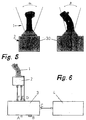
Figur 5 - zwei Seitenansichten der Bedieneinrichtung gemäß
Figur 1 mit Angabe der jeweiligen Auslenkungswinkelbereiche, - Figur 6
- eine prinzipielle Ansicht des Anschlusses von Bedieneinrichtung, elektronischer Einheit und Datenverarbeitungsstation,
- Figur 7
- eine schematische Darstellung der Regelkreise der Aktuatoreinheit,
- Figur 8
- eine schematische Darstellung eines Blockschaltbildes zur Verdeutlichung der Ansteuerung der Aktuatoreinheit,
- Figur 9
- ein Diagramm der Auftragung von Kraft bzw. Drehmoment über dem Auslenkungswinkel der Bedieneinrichtung bei konstantem Strom,
-
Figur 10 - eine Feldbilddarstellung für eine erfindungsgemäße Bedieneinrichtung mit Einfachanordnung von Permanentmagnet-Scheibenelementen im unausgelenkten Zustand,
-
Figur 11 - eine
Feldbilddarstellung wie Figur 10 im ausgelenkten Zustand, -
Figur 12 - eine
Feldbilddarstellung wie Figur 10 im ausgelenkten Zustand, -
Figur 13 - eine Feldbilddarstellung für eine erfindungsgemäße Bedieneinrichtung mit Doppelanordnung von Permanentmagnet-Scheibenelementen im unausgelenkten Zustand,
-
Figur 14 - eine
Feldbilddarstellung wie Figur 13 im ausgelenkten Zustand, -
Figur 15 - eine
Feldbilddarstellung wie Figur 13 im ausgelenkten Zustand, -
Figur 16 - eine
Feldbilddarstellung wie Figur 13 im ausgelenkten Zustand, und - Figur 17
- eine Ansicht einer anderen Ausführungsform mit schwenkbarem Stator und ortsfest gelagertem Rotor.
- Figure 1
- 2 shows a sectional side view of a first embodiment of an electromechanical control device according to the invention,
- Figure 2
- 2 shows a cross-sectional view through the actuator unit of the operating device according to FIG. 1,
- Figure 3
- 2 shows a sectional view of the operating device according to FIG. 1 in a position rotated by 90 °,
- Figure 4
- 2 shows a perspective view of the operating device according to FIG. 1,
- Figure 5
- two side views of the operating device according to FIG. 1 with details of the respective deflection angle ranges,
- Figure 6
- a basic view of the connection of the operating device, electronic unit and data processing station,
- Figure 7
- 1 shows a schematic illustration of the control loops of the actuator unit,
- Figure 8
- 1 shows a schematic representation of a block diagram to illustrate the actuation of the actuator unit,
- Figure 9
- 1 shows a diagram of the application of force or torque over the deflection angle of the operating device at constant current,
- Figure 10
- 2 shows a field image representation for an operating device according to the invention with a simple arrangement of permanent magnet disk elements in the undeflected state,
- Figure 11
- 10 shows a field image representation like FIG. 10 in the deflected state,
- Figure 12
- 10 shows a field image representation like FIG. 10 in the deflected state,
- Figure 13
- 2 shows a field image representation for an operating device according to the invention with a double arrangement of permanent magnet disk elements in the undeflected state,
- Figure 14
- 13 shows a field image representation as in FIG. 13 in the deflected state,
- Figure 15
- 13 shows a field image representation as in FIG. 13 in the deflected state,
- Figure 16
- a field image representation like Figure 13 in the deflected state, and
- Figure 17
- a view of another embodiment with a pivotable stator and stationary rotor.
In Figur 1 ist eine seitliche Schnittansicht einer ersten Ausführungsform einer
elektromechanischen Bedieneinrichtung dargestellt. Die Bedieneinrichtung weist
einen Bedienhebel 1 auf. Dieser ist mit einer Aktuatoreinheit 2 verbunden. Er ist
gegenüber dieser in unterschiedlichen Richtungen kippbar. Diese Kippbarkeit
wird durch ein Gelenk 30 innerhalb der Aktuatoreinheit 2 geschaffen. Dieses ist
einerseits über ein erstes Gelenkelement 32 mit einer Montageplatte 31 der
Aktuatoreinheit verbunden. Andererseits ist es über ein zweites Gelenkelement
33 mit dem Bedienhebel 1 verbunden. FIG. 1 shows a sectional side view of a first embodiment of an electromechanical control device. The operating device has an operating
Um das Gelenk 30 und die Gelenkelemente 32, 33 herum ist ein im folgenden
als Rotor 20 bezeichnetes bewegliches, schwenkbares Teil der Aktuatoreinheit
2 vorgesehen. Achse dieses Rotors 20 ist die senkrecht gezeichnete
Achse 14 der Bedieneinrichtung. Sie ist oder muß nicht eine Drehachse für den
Rotor 20 sein. Der Rotor 20 weist ein Metallkugelelement 23, insbesondere eine
Stahlkugel, mit äußeren Scheibenelementen 21 sowie einem mittleren Element
24 auf. Diese sind in axialer Richtung, das ist die Richtung der gezeichneten
Achse, von Permanentmagnet-Ringelementen 22 unterbrochen. In der Ausführungsform
gemäß Figur 1 sind zwei solcher Permanentmagnet-Ringelemente
22 vorgesehen. Vorzugsweise sind die Permanentmagnet-Ringelemente in
axialer Richtung magnetisiert. Das Metallkugelelement 23 besteht bevorzugt aus
ferromagnetischem Material, insbesondere Stahl. Bei jeder Schwenkung des
Rotors 20 um die Gelenke 32, 33 sind die genannten axialen Richtungen also
nicht mehr deckungsgleich mit der gezeichneten Achse 14 der
Bedieneinrichtung.Around the joint 30 and the
Der Rotor ist inmitten eines Stators 10 beweglich angeordnet. Der Stator 10
weist direkt den Rotor 20 umlagernde Pole 11 auf. Diese sind im wesentlichen
ringförmig um den Rotor 20 angeordnet. Sie weisen mehr oder weniger tiefe
Nuten 12 auf. Am Ort oder innerhalb dieser Nuten 12 sind jeweils stromführende
Leiterelemente 13 angeordnet. Die Tiefe der Nuten 12 kann auch Null werden,
wenn gedruckte Spulen oder Flachspulen verwendet werden. Bevorzugt sind
die Pole aus ferromagnetischem Material gefertigt, wodurch aufgrund des in den
stromführenden Leiterelementen fließenden Stromes innerhalb der Nuten der
Pole sich der dadurch entstehende magnetische Fluß über die inmitten der Pole
beweglich angeordnete Erregeranordnung des Rotors 20 schließt.The rotor is movably arranged in the middle of a
Das in den Nuten 12 der Pole 11 angeordnete jeweilige stromführende Leiterelement
13 ist vorzugsweise Bestandteil von zumindest jeweils einer Spule je Pol
11. Eine solche Spule wird mit einem nach Betrag und Vorzeichen variablen
Strom gespeist.The respective current-carrying conductor element arranged in the
Anstelle der zwei in axialer Richtung übereinander angeordneten Permanentmagnet-Ringelemente
des Rotors 20 kann auch lediglich ein Permanentmagnet-Ringelement
als Ringscheibe angeordnet werden. Die jeweilige Spule eines
Poles lagert dabei mit ihren Seiten in zwei in axialer Richtung übereinander angeordneten
Nuten 12, wobei in Figur 1 lediglich die Spule dargestellt ist.Instead of the two permanent magnet ring elements arranged one above the other in the axial direction
of the
In Figur 2 ist eine Querschnittsansicht der Aktuatoreinheit 2 gezeigt. Dabei ist
besonders die geometrische Gestaltung der Pole 11 deutlicher sichtbar. Die
stromführenden Leiterelemente 13 sind gestrichelt dargestellt. Durch entsprechende
Wahl der geometrischen Gestaltung der Pole und/oder Ausführung der
Spulen hinsichtlich ihrer stromführenden Leiterelemente 13 kann auch die jeweilige
Achse der Kraftwirkung für die ringförmig angeordneten Pole unterschiedlich
gestaltet werden. Bei symmetrischer Verteilung der Pole um die Erregeranordnung
des Rotors 20 ist die Kraftwirkung in den beiden Richtungen (Nick- oder
Rollrichtung) gleich, wenn, wie in Figur 2 dargestellt, jeweils Paare von
Polen gebildet werden, die bezogen auf die jeweilige Achse der Kraftwirkung,
paarweise unterschiedliche geometrische Winkel ihrer Anordnung innerhalb der
Aktuatoreinheit aufweisen. Dadurch wird erreicht, daß für die Kraftwirkung die
Eigentümlichkeiten der menschlichen Hand berücksichtigt werden, nämlich, daß
eine Kraft vom menschlichen Körper weg stärker ist als die seitlich dazu. A cross-sectional view of the
Anstelle lediglich einer Spule in einer Nute 12 eines Pols 11 können alternativ
auch mehrere elektrisch voneinander getrennte Spulen innerhalb der Nuten
angeordnet sein. Anstelle einer solchen Anordnung von mehreren voneinander
getrennten Spulen in den jeweiligen Nuten 12 eines Poles 11 kann auch eine
getrennte Speisung dieser getrennten Spulen erfolgen. Dadurch wiederum kann
eine funktionale Redundanz geschaffen werden, da jede Spule für sich wirkt.
Ein Ausfall von einer Spule führt dadurch nicht zum Gesamtausfall des
Systems. Die Pole 11 können in Richtung auf die Achse 14 verschoben werden.
Schrauben 15 und Langlöcher 16 deuten dies an. Zu diesem Zweck sind die
Pole 11 auf der Grundplatte 31 nach Art einer Schwalbenschwanzverbindung
verschiebbar gelagert. Die Pole können auch zwecks Justierung der Symmetrie
oder Unsymmetrie.entlang eines Kreisbogens um die Achse 14 verschoben
werdenAlternatively, instead of just one coil in a
Figur 3 zeigt eine weitere Schnittansicht der Bedieneinrichtung gemäß Figur 1.
Dabei sind die Pole nun in der jeweilig anderen Querschnittsansicht zu sehen.
Der Bedienhebel 1 kann nicht nur in Richtung des Pfeiles gemäß Figur 1, sondern
auch in Richtung des Pfeiles gemäß Figur 3 ausgelenkt werden. Auch dieses
läßt das kordanische Gelenk 30 zu. Um bei kleinen Auslenkwinkeln die
Kraftbildung bzw. Drehmomentbildung zu erhöhen, werden anstelle nur eines
Permanentmagnet-Ringelementes 22 mehrere von diesen übereinander mit
jeweils dazwischen angeordneten Scheibenelementen 21 des Metallkugelelementes
23 vorgesehen. Dies bedeutet also einen konstruktiven Freiheitsgrad
zur Anpassung an jeweils kleine Auslenkwinkel. FIG. 3 shows a further sectional view of the operating device according to FIG. 1. The poles can now be seen in the respective other cross-sectional view. The operating
Auch der Abstand der Pole von dem Gelenk 30 als Erregeranordnungsdreh- und Lagerpunkt kann unterschiedlich variiert werden. Dadurch kann ebenfalls eine Anpassung der Kräfte an die jeweiligen Anforderungen des Einzelfalles vorgenommen werden.Also the distance of the poles from the joint 30 as the excitation arrangement rotation and The bearing point can be varied in different ways. This can also an adjustment of the forces to the respective requirements of the individual case be made.
Es ist weiterhin möglich, die Pole in Kreisrichtung verschiebbar zu lagern, um die Pole sowohl in symmetrischer als auch in unsymmetrischer Position einstellbar zu machen. It is also possible to mount the poles so that they can move in a circular direction the poles can be adjusted in both symmetrical and asymmetrical positions close.
Figur 4 zeigt eine perspektivische Ansicht der Bedieneinrichtung gemäß Figur 1.
Deutlich zu erkennen ist dabei die Anordnung des kugelförmigen Rotors 20 mit
den beiden oben und unten angeordneten Permanentmagnet-Ringelementen
22. Diese sind eingefügt in das Metallkugelelement 23. Dieses weist die beiden
außenseitigen (oberen und unteren) Scheibenelemente 21 auf sowie das mittlere
Element 24. FIG. 4 shows a perspective view of the operating device according to FIG. 1. The arrangement of the
Da ein Stator 10 lediglich zur Hälfte dargestellt ist, wird der Einblick auf das
Metallkugelelement 23 ermöglicht. Das stromführende Leiterelement 13 des
Stators 10 ist dabei verdeutlicht. Vorzugsweise ist dieses als Erregerspule eine
Kupferwicklung. Der Pol 11 bzw. die Pole 11 sind vorzugsweise aus Eisen gefertigt.Since only half of a
Figur 4 ist auch die räumliche Anordnung des Bedienhebels 1 deutlich zu entnehmen.
Dieser kann in verschiedene Raumrichtungen geschwenkt werden und
nimmt dabei das Metallkugelelement und somit den Rotor 20 mit. Die
Schwenkmöglichkeiten sind Figur 5 zu entnehmen.FIG. 4 also clearly shows the spatial arrangement of the operating
In Figur 5 ist, jeweils als Seitenansicht, die Ansicht gemäß Figur 3 und daneben die Ansicht gemäß Figur 1 der elektromechanischen Bedieneinrichtung dargestellt. Skizziert sind dabei jeweils die möglichen Auslenkwinkel α und β, bezogen auf den Drehpunkt der Erregeranordnung in Form des Gelenkes 30. Beispielsweise kann der Winkel α zwischen -20° und +20° bei einer maximalen Kraft Fmax von 50 N gewählt werden. Der Winkel β kann beispielsweise bei einer aufzuwendenden Kraft von Fmax= 120 N zwischen +16° und -16° betragen. FIG. 5 shows the side view of the view according to FIG. 3 and the view according to FIG. 1 of the electromechanical control device. The possible deflection angles α and β, based on the pivot point of the exciter arrangement in the form of the joint 30, are sketched in each case. For example, the angle α can be chosen between -20 ° and + 20 ° with a maximum force F max of 50 N. The angle β can, for example, be between + 16 ° and -16 ° with a force of F max = 120 N to be applied.
Die Abmessungen der Aktuatoreinheit betragen beispielsweise 130 mm mal 165 mm. Die Höhe der Aktuatoreinheit kann dann zu 95 mm gewählt werden. Der Abstand der mit einem Kreuz gekennzeichneten Mitte des Bedienhebels zu dem Drehpunkt in Form des Gelenkes 30 beträgt beispielsweise 140 mm bei einer Gesamthöhe der elektromechanischen Bedieneinrichtung von 261 mm. The dimensions of the actuator unit are, for example, 130 mm by 165 mm. The height of the actuator unit can then be selected to be 95 mm. Of the Distance from the center of the control lever marked with a cross to that The pivot point in the form of the joint 30 is, for example, 140 mm at one Total height of the electromechanical control device of 261 mm.
Figur 6 zeigt die elektrischen Schnittstellen zwischen elektromechanischer Bedieneinrichtung
mit Aktuatoreinheit 2 und einer Elektronikeinheit 3 sowie einer
Datenverarbeitungseinheit 4. Die Aktuatoreinheit 2 sendet über eine Leitung F
Signale zu der Elektronikeinheit 3. Die Elektronikeinheit ihrerseits ist an eine
Stromversorgung A angeschlossen und versorgt ebenfalls die Aktuatoreinheit
über eine Leitung E mit Strom. Eine weitere Leitung D führt von dem Bedienhebel
1 direkt zur Elektronikeinheit. Über diese wird der Auslenkwinkel erfaßt
und übermittelt. FIG. 6 shows the electrical interfaces between the electromechanical operator control device with
Die Elektronikeinheit 3 ist mit einer RS 232-Schnittstelle B versehen, um an
einen Rechner angeschlossen werden zu können. Darüberhinaus ist sie über
eine Leitung C, nämlich einen Datenbus, insbesondere einen luftfahrtspezifischen
Datenbus für Avioniksysteme, mit der Datenverarbeitungseinheit 4
verbunden.The
In den folgenden Figuren 7 und 8 ist näher der innere Aufbau der Schaltungen bzw. Steuer- und Regelkreise der Stromversorgung von Aktuatoreinheit und Elektronikeinheit dargestellt. Ausgehend von der Bedieneinrichtung wird durch die bedienende Hand ein Moment MH in Richtung des oberen Pfeiles ausgeübt. Der Bedienhebel zeigt dadurch ein in entgegengesetzter Richtung wirkendes Moment MB. Der Regelkreis funktioniert dann wie folgt:In the following Figures 7 and 8 , the inner structure of the circuits or control and regulating circuits of the power supply of the actuator unit and electronics unit is shown. Starting from the operating device, the operating hand exerts a moment M H in the direction of the upper arrow. The operating lever thereby shows a torque M B acting in the opposite direction. The control loop then works as follows:
Zunächst wird die Position des ausgelenkten Bedienhebels 1 mittels eines Sensormittels
40 erfaßt. Dieses wirkt vorzugsweise optisch. Diese Position stellt die
Ist-Position dar. Von außen wird dann eine Soll-Position 41 auf eine Summationsstelle
aufgegeben. Diese ist in einen Mikrocontroller 42 implementiert. Es
wird zwischen der Soll-Position 41 und der von dem Sensormittel 40 ermittelten
Ist-Position eine Verknüpfung vorgenommen und als Parameter 43 angegeben.
Diesem werden zusätzliche Daten 44 aufgegeben. Der Parameter 43 beinhaltet
beispielsweise das über der Auslenkung aufgetragene Moment M, die
Dämpfung Da sowie die vorgegebenen Anregungsschwingungsformen als
Rechteck- oder Sinusschwingung oder als Impuls. Aus diesen Parametern wird
ein Sollstrom 45 gebildet. Dieser wird auf eine Summationsstelle zur Regelung
des Stromes in einem Stromregelkreis 46 aufgegeben. Der entsprechend geregelte
Strom wird den Polen und Spulen zuführt, hier in Form des Kästchens
47 dargestellt.First, the position of the deflected
Durch Zusammenwirken der Pole und Spulen ergibt sich das magnetische Feld
48, welches auf den Rotor wirkt. Dieser ist hier durch das Kästchen 49 symbolisiert.The magnetic field results from the interaction of the poles and coils
48, which acts on the rotor. This is symbolized here by
Der Rotor wiederum wirkt auf die Bedieneinrichtung zurück, genau genommen
auf das Moment MB des Bedienhebels 1.The rotor in turn reacts on the operating device, to be precise on the moment M B of the operating
Stromregelkreis 46, Pole und Spulen 47, magnetisches Feld 48 und Rotor 49
bilden zusammen den elektromagnetischen Aktuator.
Figur 8 zeigt eine Trennung des Bedienhebels 1 und der Aktuatoreinheit (AU) 2
sowie der Elektronikeinheit 3. Der Bedienhebel weist eine Leuchtdiode als Statusanzeige
auf seiner Oberseite auf. Darüberhinaus weist der Bedienhebel 1
seitlich einen Schalter 51 auf. Über diesen Schalter können Signale an die
Elektronikeinheit 3 gesandt werden. Beispielsweise können solche Signale
spezifische Schaltersignale, u.a. sog. SIM-OFFs, Priority-Daten oder sog. Funkschalter- oder COM-Daten sein. Figure 8 shows a separation of the
Der Elektronikeinheit 3 werden weiterhin die Nick- und die Rollposition des Bedienhebels
eingegeben. Dabei gibt es jeweils eine positive und eine negative
Auslenkung, welche jeweils mit einer Datenleitung 1. und 2. angezeigt ist. Die
jeweiligen Ist-Werte der Nickpositionen 60, 61 sowie die jeweiligen Ist-Werte der
Rollpositionen 62, 63 des Hebels 1 werden in eine Signalaufbereitungseinheit
SCU, Bezugszeichen 64 eingegeben. Zusammen mit den Schaltersignalen vom
Schalter 51 werden sie zur Duplex-DVS, also zur Datenverarbeitungseinheit 4,
weitergegeben. Eine weitere Information ist dabei die Statusangabe (vgl.
Leuchtdiode 50), welche ebenfalls als Information an die Duplex-DVS gegeben
wird.The
Von der Duplex-DVS (Datenverarbeitungseinheit 4) gelangen ebenfalls Informationen
in Form von Daten zu der Elektronikeinheit 3 zurück, nämlich Soll-Werte
und ermittelte Regelabweichungen. Hierbei sind die Kennlinienparameter für die
Nick- und Rollposition, die Dämpfung für die Nick- und Rollposition, die Nick- und
Rollposition selbst, die Statusanzeige (An/Aus) sowie die Excitation
(An/Aus), also die Anzeige der Auslenkung des Bedienhebels als Anzeigen der
Systemzustände enthalten.Information also comes from the duplex DVS (data processing unit 4)
back to the
All diese Daten werden zusammen mit der aufgenommenen Nick- und Rollposition
einer Regeleinheit 70 aufgegeben. Diese ist vorzugsweise als Mikroprozessor
mit einer RS 232-Schnittstelle zu einem Rechner ausgebildet.All of this data is recorded along with the pitch and roll position
a
Über P1 und P2 wird die Elektronikeinheit 3 mit Strom versorgt.The
Von der Regeleinheit 70 werden die Ausgangsdaten auf eine Stromstellereinheit
71 aufgegeben. Durch diese werden die Spulenströme entsprechend gesteuert.
Letztendlich findet also durch extern zugeführte Signale, welche der Regeleinheit
aufgegeben werden, welche wiederum auf die nachfolgende Stromstellereinheit
wirkt, eine entsprechende Steuerung bzw. Regelung der Ströme
der Spulen innerhalb der Nuten der Pole des Stators statt. Dieses Einwirken der
Stromstellereinheit 71 auf die Aktuatoreinheit (AU) 2 ist ebenfalls in Figur 8
durch Pfeile skizziert.The output data are sent from the
Die erfindungsgemäße elektromechanische Bedieneinrichtung ist also extrem
kompakt und weist nur ein zentrales kardanisches Gelenk 30 auf. Darüberhinaus
zeigt die Bedieneinrichtung nur geringe Reibung und Totzonen. Der
Aktuator ist vorteilhaft integriert als zentraler elektromagnetischer Aktuator.
Darüberhinaus sind auch keine beweglichen Stangen oder Teile für die Bedieneinrichtung
erforderlich, insbesondere sind weder Kraftsensoren noch Tachogeneratoren,
Zahnräder oder Kupplungen erforderlich. Vorteilhaft sind Selbstzentrierungskräfte
nach Wegfall der Stromversorgung vorgesehen. Die jeweilige
Position des Bedienhebels wird optisch gemessen. Eine hohe Bandbreite wird
durch Unterbrecher (Chopper) mit einer Frequenz von 20 kHz und
Mikroprozessoren mit einer Abtastrate von 400 µs vorgesehen. Vorteilhaft
entsteht kein Lärm bei der Bedienung. Die Kräfte werden einwandfrei erzeugt,
ohne daß durch Stromschwankungen überlagerte Störmoden auftreten. Die
erfindungsgemäße elektromechanische Bedieneinrichtung ist daher ideal
geeignet für eine hochfrequente Abtastregelung.The electromechanical control device according to the invention is therefore extreme
compact and has only one
Zusätzlich zu den in den Figuren 1 bis 4 dargestellten Ausführungsformen lassen sich auch größere und hinsichtlich ihrer Formgebung anders gestaltete elektromechanische Bedieneinrichtungen im Sinne der Erfindung schaffen. Diese sind vorteilhaft jedoch stets kleiner dimensioniert und leichter als entsprechende passive Bedieneinrichtungen oder aktive Bedieneinrichtungen mit Servomotoraktivierung.In addition to the embodiments shown in Figures 1 to 4 larger and different in shape Create electromechanical control devices in the sense of the invention. However, these are advantageously always smaller in size and lighter than corresponding ones passive controls or active controls with Servo motor activation.
In Figur 9 ist ein Diagramm dargestellt, das in Auftragung der durch den eingestellten Strom (konstanter Strom) eingestellten Kraft F in N oder des erzeugten Drehmomentes M in Nm über dem Auslenkungswinkel α ein Kennlinienfeld zeigt, innerhalb dessen sich verschiedenste Kennlinienverläufe realisieren lassen. Zugrundegelegt sind für die Grenzlinien die Verläufe bei maximalem Strom I = ±15 A sowie bei I = 0 A, wobei in letzterem Fall lediglich die durch die Permanentmagnet-Ringelemente erzeugten Kräfte wirken. Die in dem mittleren Bereich des Feldes dargestellte, die I = 0 A - Linie schneidende Kennlinie mit geraden Teilabschnitten stellt eine für Flugbedingungen typische Kennlinie dar. FIG. 9 shows a diagram which, plotted against the force F in N set by the set current (constant current) or the torque M generated in Nm above the deflection angle α, shows a characteristic field within which a wide variety of characteristic curves can be realized. The curves are based on the curves at maximum current I = ± 15 A and at I = 0 A, in the latter case only the forces generated by the permanent magnet ring elements act. The characteristic curve which intersects the I = 0 A line and has straight sections in the middle of the field represents a characteristic curve typical of flight conditions.
Die Figuren 10 bis 16 zeigen Feldverläufe, eingezeichnet in eine Querschnittsansicht
durch die Bedieneinrichtung gemäß Figur 1, bzw. eine alternative
Ausführungsform von dieser. Figur 10 gibt dabei den Feldverlauf durch eine
Bedieneinrichtung mit einfacher Permanentmagnet-Ringelement-Anordnung
wieder. Das Ringelement 22 ist mittig zwischen den beiden Metallkugelelementsegmenten
25 des Rotors 20 angeordnet. Im nicht-ausgelenkten
Zustand (Figur 10) verlaufen die Feldlinien innerhalb von Stator 10 und Rotor 20
auf beiden Seiten spiegelsymmetrisch. Bei der Auslenkung 0 Grad ist einerseits
eine Durchflutung von bis zu ±2 kA bzw. ein Drehmoment von ±4,56 Nm oder
aber eine Durchflutung von bis zu ±4 kA bzw. ein Drehmoment von ±10,4 Nm
vorgesehen. Die Tiefe der Bedieneinrichtung beträgt 40 mm.FIGS. 10 to 16 show field profiles drawn in a cross-sectional view through the operating device according to FIG. 1, or an alternative embodiment thereof. FIG. 10 shows the field profile through an operating device with a simple permanent magnet ring element arrangement. The
In Figur 11 ist ein Auslenkungswinkel von 20 Grad dargestellt. Die Durchflutung beträgt entweder bis zu -2 kA oder -4 kA entsprechend einem Drehmoment von +19,2 Nm bzw. +28 Nm. Die Feldlinien laufen nun außerhalb von Stator und Rotor, was das Auftreten der entsprechend gewünschten Stellkraftsignale anzeigt.A deflection angle of 20 degrees is shown in FIG . The flow is either up to -2 kA or -4 kA corresponding to a torque of +19.2 Nm or +28 Nm. The field lines now run outside of the stator and rotor, which indicates the occurrence of the desired actuating force signals.
Figur 12 zeigt denselben Auslenkungswinkel von 20 Grad bei jedoch einer Durchflutung von bis zu +2 kA oder +4 kA, entsprechend einem Drehmoment von -4,4 bzw. -0,28 Nm. Der Feldlinienverlauf zeigt deutlich das entgegengesetzt wirkende Drehmoment. Der Feldverlauf ist nicht mehr kontinuierlich durch den Stator gehend, sondern bildet Feldlinien um die Zentren der Wicklungen herum. FIG. 12 shows the same deflection angle of 20 degrees but with a flooding of up to +2 kA or +4 kA, corresponding to a torque of -4.4 or -0.28 Nm. The field line course clearly shows the opposing torque. The field course is no longer continuous through the stator, but forms field lines around the centers of the windings.
Figur 13 zeigt den Feldinienverlauf bei einer Bedieneinrichtung mit zwei Permanentmagnet-Ringelementen,
wie sie bereits in Figur 1 zu sehen ist. In der Position
gemäß Figur 13 ist die Bedieneinrichtung nicht ausgelenkt. Es stellt sich
dabei ein verhältnismäßig gleichförmiger Feldlinienverlauf ein. Dieser ist drehsymmetrisch
hinsichtlich des Mittelpunktes des Rotors 20. Die Feldlinien
drängen dabei von dem Mittelpunkt des Rotors weg in Richtung nach außen. FIG. 13 shows the field line course in the case of an operating device with two permanent magnet ring elements, as can already be seen in FIG. 1. In the position according to FIG. 13, the operating device is not deflected. This results in a relatively uniform field line course. This is rotationally symmetrical with respect to the center of the
Bei der Auslenkung 0 Grad wird eine Durchflutung von ±2 kA bzw. ein Drehmoment von ±11,2 Nm vorgehalten, d.h. im Rahmen der Steuerung möglich gemacht, bei einer Tiefe von 40 mm (Tiefe der Bedieneinrichtung).With a deflection of 0 degrees, a flooding of ± 2 kA or a Torque of ± 11.2 Nm available, i.e. as part of the control system made possible at a depth of 40 mm (depth of the control device).
Figur 14 zeigt die Ausführungsform der Bedieneinrichtung gemäß Figur 13 in Auslenkung um einen Winkel von 20 Grad bei einer Durchflutung von 1 kA bzw. einem Moment von 3,88 Nm. Es bildet sich dadurch weiterhin eine im wesentlichen drehsymmetrische Anordnung der Feldlinien aus. Dies beruht im wesentlichen auf der Anordnung der beiden Permanentmagnet-Ringelemente in dem Unterschied zu dem lediglich in der Mitte angeordneten einen Permanentmagnet-Ringelement gemaß der Figuren 10 bis 12. Die Feldlinien verlaufen bei der Auslenkung gemäß Figur 14 allerdings ebenfalls außerhalb von Stator und Rotor. Die Feldlinien bilden sich jeweils dort, wo die Permanentmagnet-Ringelemente an schmalere Eckbereiche des Stators bzw. der Pole treffen, konzentriert um diese Bereiche herum aus. FIG. 14 shows the embodiment of the operating device according to FIG. 13 deflected by an angle of 20 degrees with a flooding of 1 kA or a moment of 3.88 Nm. As a result, an essentially rotationally symmetrical arrangement of the field lines is formed. This is based essentially on the arrangement of the two permanent magnet ring elements, in contrast to the one permanent magnet ring element arranged only in the middle according to FIGS. 10 to 12. However, during the deflection according to FIG. 14, the field lines also run outside of the stator and rotor. The field lines form where the permanent magnet ring elements meet narrower corner areas of the stator or the poles, concentrated around these areas.
Im Unterschied zu Figur 14 zeigt Figur 15 eine Auslenkung von 20 Grad bei
jedoch einer Durchflutung von -2 kA bzw. einem Drehmoment von +14,4 Nm.
Der Feldlinienverlauf zeigt sich hier sehr viel weiter nach außen tretend und in
den Eckbereichen konzentrierter als bei dem in Figur 14 dargestellten. In dieser
Figur sind im Rotor 20 Nuten 26 vorgesehen, mit denen der Feldverlauf
beeinflußbar ist. Diese Nut wirkt auf die Bewegung des Hebels 1 wie ein
Druckpunkt oder eine Raststellung. Auch kann dadurch die Kraftwirkung für
kleine Winkel erhöht werden. Die äußere rechteckige Feldlinienbegrenzung ist
nicht durch magnetische Eigenschaften einer Platte gegeben, sondern durch ein
Zeichnungsverfahren.In contrast to FIG. 14, FIG. 15 shows a deflection of 20 degrees with a flow of -2 kA or a torque of +14.4 Nm. The course of the field lines shows itself here much further outwards and is more concentrated in the corner areas than in the case shown in FIG. 14. In this figure 20
Werden bei einer Auslenkung von 20 Grad anstelle der -2 kA jetzt +2 kA bzw. ein Drehmoment von -2,34 Nm vorgesehen, ergibt sich der Feldlinienverlauf gemäß Figur 16. Dieser ist sehr gleichförmig, wobei sich insbesondere in den Polen des Stators nahezu spiegelsymmetrische Verläufe ergeben, und auch in den beiden äußeren Scheibenelementen des Rotors verhältnismäßig gleichmäßig verteilte Linienverläufe auftreten.If a deflection of 20 degrees instead of -2 kA or +2 kA or a torque of -2.34 Nm is now provided, the field line profile according to FIG. 16 is obtained. This is very uniform, with almost in particular in the poles of the stator result in mirror-symmetrical courses, and also occur in the two outer disk elements of the rotor relatively evenly distributed line courses.
Aus den vorhergehenden Figuren wird deutlich, daß bei Mehrfachanordnung von Permanentmagnet-Ringelementen die Kraftwirkung erhöht wird durch Multiplikation der Feldeinflüsse bei der Auslenkung. Hierbei ist die Anzahl der Ringelemente von besonders großer Bedeutung, was insbesondere aus dem Vergleich der Figuren 10 bis 12 bzw. 13 bis 16 hervorgeht.From the previous figures it is clear that with multiple arrangement the force effect of permanent magnet ring elements is increased by multiplication the field influences during the deflection. Here is the number of ring elements of particular importance, which in particular from the Comparison of Figures 10 to 12 and 13 to 16 shows.
Figur 17 zeigt eine Abwandlung, bei der der Rotor 20 fest angeordnet und der
Stator schwenkbar ist. Figure 17 shows a modification in which the
Mit Bedieneinrichtungen gemäß den Figuren 1 bis 17 kann also eine Bedienung
ausgeführt und über die elektronische Steuerung und über die Spulen sofort
eine Rückwirkung ausgelöst werden. Es ist aber auch für Lehrzwecke möglich,
die Steuerung auf eine Vielzahl von Schülereinrichtungen wirken zu lassen. Die
Konstruktion erlaubt weiterhin die oder viele Bedieneinrichtungen willkürlich zu
steuern, beispielsweise durch ein Computerprogramm oder Fernsteuerung. Die
so gesteuerte Bewegung des Bedienungshebels 1 wirkt wie die bekannte
mechanische Mitführung der Steuereinrichtung eines Copiloten. Die Neigung
des Rotors 20 kann beispielsweise durch ein Kardangelenk oder eine
Kugelkopflagerung innerhalb des Rotors 20 ermöglicht werden. Dabei kann der
Rotor zusätzlich auch noch um die Achse 14 gedreht werden.With control devices according to Figures 1 to 17, an operation can
executed and immediately via the electronic control and the coils
a retroactive effect can be triggered. But it is also possible for teaching purposes
to let the control affect a multitude of student institutions. The
Construction continues to arbitrarily allow one or many controls
control, for example by a computer program or remote control. The
thus controlled movement of the operating
Bei einem bevorzugten Ausführungsbeispiel ist eine Neigung in Richtung eines
Meridians um bis zu ± 20 ° (Azimutwinkel) vorgesehen und eine Verdrehung um
die Achse 14 ohne Beschränkung. Die Permanentmagnete können, wie
dargestellt, axial magnetisiert werden, aber auch radial, wie in Figur 18 gezeigt.
Eine inhomogene Magnetisierung könnte genutzt werden, um eine Zentrierung
des beweglichen Teils um die axiale Achse zu erreichen. In a preferred exemplary embodiment, an inclination in the direction of a meridian of up to ± 20 ° (azimuth angle) is provided and a rotation about the
- 11
- BedienhebelOperating lever
- 22nd
- Aktuator-EinheitActuator unit
- 33rd
- Elektronik-EinheitElectronics unit
- 44th
- DatenverarbeitungseinheitData processing unit
- 1010th
- Statorstator
- 1111
- Polpole
- 1212th
- Nutegroove
- 1313
- stromführendes Leiterelementcurrent conducting element
- 1414
- Achseaxis
- 1515
- SchraubenScrews
- 1616
- LanglochLong hole
- 2020th
- Rotorrotor
- 2121
- ScheibenelementDisc element
- 2222
- Permanentmagnet-RingelementPermanent magnet ring element
- 2323
- MetallkugelelementMetal ball element
- 2424th
- mittleres Elementmiddle element
- 2525th
- Metallkugelelement-SegmentMetal ball element segment
- 2626
- NutenGrooves
- 3030th
- Gelenkjoint
- 3131
- MontageplatteMounting plate
- 3232
- GelenkelementJoint element
- 3333
- GelenkelementJoint element
- 4040
- SensormittelSensor means
- 4141
- SollpositionTarget position
- 4242
- MikrocontrollerMicrocontroller
- 4343
- Parameterparameter
- 4444
- Daten Data
- 4545
- Soll-StromTarget current
- 4646
- StromregelkreisCurrent control loop
- 4747
- Pole und SpulenPoles and coils
- 4848
- magnetisches Feldmagnetic field
- 4949
- Rotorrotor
- 5050
- LEDLED
- 5151
- Schaltercounter
- 6060
-
Nickposition 1
Pitch position 1 - 6161
-
Nickposition 2
Pitch position 2 - 6262
-
Rollposition 1Roll
position 1 - 6363
-
Rollposition 2Roll
position 2 - 6464
- SCUSCU
- 7070
- RegeleinheitControl unit
- 7171
- StromstellereinheitCurrent control unit
- αα
- AuslenkwinkelDeflection angle
- ββ
- AuslenkwinkelDeflection angle
- P1P1
- StromversorgungPower supply
- P2P2
- StromversorgungPower supply
- AA
- StromversorgungsanschlußPower connector
- BB
-
RS 232-Schnittstelle
RS 232 interface - CC.
- Leitung (Daten)Management (data)
- DD
- Leitung (Position)Head (position)
- EE
- Leitung (Stromversorgung)Line (power supply)
- FF
- Leitung (Signale)Line (signals)
Claims (22)
dadurch gekennzeichnet,
characterized,
dadurch gekennzeichnet,
characterized,
dadurch gekennzeichnet,
characterized,
dadurch gekennzeichnet,
characterized,
dadurch gekennzeichnet,
characterized,
dadurch gekennzeichnet,
characterized,
dadurch gekennzeichnet,
characterized,
dadurch gekennzeichnet,
characterized,
dadurch gekennzeichnet,
characterized,
dadurch gekennzeichnet,
characterized,
dadurch gekennzeichnet,
characterized,
dadurch gekennzeichnet,
characterized,
dadurch gekennzeichnet,
characterized,
dadurch gekennzeichnet,
characterized,
dadurch gekennzeichnet,
characterized,
dadurch gekennzeichnet,
characterized,
dadurch gekennzeichnet,
characterized,
dadurch gekennzeichnet,
characterized,
dadurch gekennzeichnet,
characterized,
dadurch gekennzeichnet,
characterized,
dadurch gekennzeichnet,
characterized,
dadurch gekennzeichnet,
characterized,
Applications Claiming Priority (2)
| Application Number | Priority Date | Filing Date | Title |
|---|---|---|---|
| DE19806611A DE19806611C2 (en) | 1998-02-18 | 1998-02-18 | Electromechanical control device |
| DE19806611 | 1998-02-18 |
Publications (2)
| Publication Number | Publication Date |
|---|---|
| EP0938035A2 true EP0938035A2 (en) | 1999-08-25 |
| EP0938035A3 EP0938035A3 (en) | 2003-09-17 |
Family
ID=7858058
Family Applications (1)
| Application Number | Title | Priority Date | Filing Date |
|---|---|---|---|
| EP99103186A Withdrawn EP0938035A3 (en) | 1998-02-18 | 1999-02-18 | Electromechanical control device |
Country Status (2)
| Country | Link |
|---|---|
| EP (1) | EP0938035A3 (en) |
| DE (1) | DE19806611C2 (en) |
Cited By (6)
| Publication number | Priority date | Publication date | Assignee | Title |
|---|---|---|---|---|
| WO2004013803A2 (en) * | 2002-08-06 | 2004-02-12 | Engineering Matters, Inc. | Direct drive controller with haptic feedback |
| EP1400426A2 (en) * | 2002-09-23 | 2004-03-24 | Bombardier Transportation GmbH | Drive controller for a rail vehicle |
| WO2006013323A1 (en) * | 2004-08-06 | 2006-02-09 | Pg Drives Technology Ltd | Control system |
| US7119792B1 (en) | 2000-01-12 | 2006-10-10 | Apple Computer, Inc. | Cursor control device having an integral top member |
| DE102010029696A1 (en) * | 2010-06-04 | 2011-12-08 | Raytheon Anschütz Gmbh | Watercraft control with active feedback |
| WO2021223973A1 (en) * | 2020-05-07 | 2021-11-11 | Daimler Ag | Control device for controlling vehicle functions |
Families Citing this family (11)
| Publication number | Priority date | Publication date | Assignee | Title |
|---|---|---|---|---|
| US6664666B2 (en) * | 1998-12-23 | 2003-12-16 | Engineering Matters, Inc. | Motor assembly allowing output in multiple degrees of freedom |
| US9870021B2 (en) | 2009-04-15 | 2018-01-16 | SeeScan, Inc. | Magnetic manual user interface devices |
| US20120256821A1 (en) | 2010-05-18 | 2012-10-11 | Seektech, Inc. | User interface devices, apparatus, and methods |
| EP3179330B1 (en) | 2010-08-20 | 2020-03-18 | SeeScan, Inc. | Magnetic sensing user interface device |
| WO2012051357A1 (en) | 2010-10-12 | 2012-04-19 | Mark Olsson | Magnetic thumbstick user interface devices |
| EP2665989B1 (en) | 2010-11-08 | 2019-12-25 | SeeScan, Inc. | Slim profile magnetic user interface devices |
| EP3043231A1 (en) | 2010-12-02 | 2016-07-13 | SeeScan, Inc. | Magnetically sensed user interface devices |
| US9678577B1 (en) | 2011-08-20 | 2017-06-13 | SeeScan, Inc. | Magnetic sensing user interface device methods and apparatus using electromagnets and associated magnetic sensors |
| FR2979772B1 (en) | 2011-09-02 | 2019-04-05 | Safran Electronics & Defense | MULTI-AXIS MOTORIZATION DEVICE AND CONTROL INSTRUMENT EQUIPPED WITH SUCH A DEVICE |
| EP2997453B1 (en) | 2013-05-17 | 2020-10-21 | SeeScan, Inc. | User interface devices |
| FR3006291B1 (en) | 2013-06-03 | 2016-10-21 | Eurocopter France | FLY CONTROL KNOB OF A FLYING ROTARY FLYING ON A SUPPORT BY ENCASTREMENT OF A FLEXIBLE ROD |
Citations (1)
| Publication number | Priority date | Publication date | Assignee | Title |
|---|---|---|---|---|
| DE19501439A1 (en) | 1995-01-19 | 1996-09-05 | Meins Juergen Prof Dr Ing | Electromechanical detector of rotation angle for control of vehicle, aircraft or computer input |
Family Cites Families (6)
| Publication number | Priority date | Publication date | Assignee | Title |
|---|---|---|---|---|
| DE408766C (en) * | 1923-07-22 | 1925-01-26 | Aeg | High-voltage DC machine with a fixed toroidal armature winding and a rotating field magnet within it |
| DE908921C (en) * | 1942-07-21 | 1954-04-12 | Askania Werke Ag | Magnetic bridge controlled by a mechanical variable |
| DE1261581B (en) * | 1963-06-11 | 1968-02-22 | Bodenseewerk Perkin Elmer Co | Control stick arrangement, especially for aircraft controls, in which the position of the control stick is scanned electromagnetically |
| US4874998A (en) * | 1987-06-11 | 1989-10-17 | International Business Machines Corporation | Magnetically levitated fine motion robot wrist with programmable compliance |
| US5146566A (en) * | 1991-05-29 | 1992-09-08 | Ibm Corporation | Input/output system for computer user interface using magnetic levitation |
| US5410232A (en) * | 1992-12-18 | 1995-04-25 | Georgia Tech Research Corporation | Spherical motor and method |
-
1998
- 1998-02-18 DE DE19806611A patent/DE19806611C2/en not_active Expired - Fee Related
-
1999
- 1999-02-18 EP EP99103186A patent/EP0938035A3/en not_active Withdrawn
Patent Citations (1)
| Publication number | Priority date | Publication date | Assignee | Title |
|---|---|---|---|---|
| DE19501439A1 (en) | 1995-01-19 | 1996-09-05 | Meins Juergen Prof Dr Ing | Electromechanical detector of rotation angle for control of vehicle, aircraft or computer input |
Cited By (13)
| Publication number | Priority date | Publication date | Assignee | Title |
|---|---|---|---|---|
| US7119792B1 (en) | 2000-01-12 | 2006-10-10 | Apple Computer, Inc. | Cursor control device having an integral top member |
| WO2004013803A2 (en) * | 2002-08-06 | 2004-02-12 | Engineering Matters, Inc. | Direct drive controller with haptic feedback |
| WO2004013803A3 (en) * | 2002-08-06 | 2004-12-09 | Engineering Matters Inc | Direct drive controller with haptic feedback |
| US7394173B2 (en) | 2002-08-06 | 2008-07-01 | Rockwell Collins, Inc. | Direct drive controller with haptic feedback |
| EP1400426A2 (en) * | 2002-09-23 | 2004-03-24 | Bombardier Transportation GmbH | Drive controller for a rail vehicle |
| EP1400426A3 (en) * | 2002-09-23 | 2004-03-31 | Bombardier Transportation GmbH | Drive controller for a rail vehicle |
| GB2431221A (en) * | 2004-08-06 | 2007-04-18 | P G Drives Technology Ltd | Control system |
| GB2431221B (en) * | 2004-08-06 | 2008-04-09 | P G Drives Technology Ltd | Control system |
| WO2006013323A1 (en) * | 2004-08-06 | 2006-02-09 | Pg Drives Technology Ltd | Control system |
| US7411521B2 (en) | 2004-08-06 | 2008-08-12 | Pg Drives Technologies Limited | Control system |
| CN101002154B (en) * | 2004-08-06 | 2010-12-08 | Pg驱动技术有限公司 | Control system |
| DE102010029696A1 (en) * | 2010-06-04 | 2011-12-08 | Raytheon Anschütz Gmbh | Watercraft control with active feedback |
| WO2021223973A1 (en) * | 2020-05-07 | 2021-11-11 | Daimler Ag | Control device for controlling vehicle functions |
Also Published As
| Publication number | Publication date |
|---|---|
| EP0938035A3 (en) | 2003-09-17 |
| DE19806611A1 (en) | 1999-08-19 |
| DE19806611C2 (en) | 2002-11-21 |
Similar Documents
| Publication | Publication Date | Title |
|---|---|---|
| EP0938035A2 (en) | Electromechanical control device | |
| EP2150717B1 (en) | Magnetorheological torque transmission device, the use thereof, and magnetorheological torque transmission method | |
| DE2723140A1 (en) | DEVICE FOR POSITIONING OBJECTS | |
| DE3590633C2 (en) | ||
| DE3409047A1 (en) | MAGNETIC BEARING FOR TRI-AXIS BEARING STABILIZATION OF BODIES | |
| EP3243263A1 (en) | Magnetic assembly for an electric motor | |
| WO2014177133A1 (en) | Scanner device | |
| EP1832851B1 (en) | Encoder for an actuator, linear induction motor and method for manufacturing a linear motor | |
| EP0147610A2 (en) | Wave guide switch | |
| DE3640188C2 (en) | Actuator | |
| DE10393867T5 (en) | Multi-layer sensor display based on electromagnetic actuators | |
| EP3191695A1 (en) | Electromagnetic regulating device | |
| DE2129018B2 (en) | Magnetic bearing | |
| EP0920605A1 (en) | Magnetic position sensor | |
| DE10052912A1 (en) | Dual axis positioning motor has coils positioned with total volume of each coil completely within imaginary hemisphere generated about point through which armature axis passes | |
| DE2847393B2 (en) | Linear voice coil motor | |
| EP3255760A1 (en) | Electric machine | |
| DE102010042586A1 (en) | Rotatable or adjustable operating element e.g. jog dial, for use in e.g. sound or studio engineering, has magnets rotatable and/or adjustable with respect to brake disk that is connected with housing, where element is combined with brake | |
| EP0766065A2 (en) | Torquer arrangement | |
| DE3005921A1 (en) | Monostable rotary armature system - uses soft magnetic armature with inserted permanent magnet having pole which is adjacent armature pole | |
| DE19731555A1 (en) | Magnetic position sensor | |
| DE102012209274A1 (en) | Bearing device for non-contact storage of a rotatable body, arrangement and electrical reluctance machine | |
| EP1444766B1 (en) | Linear drive with moving mass-reduced passive unit | |
| DE7716251U1 (en) | DEVICE FOR POSITIONING OBJECTS | |
| DE10319081A1 (en) | Electrodynamic drive device |
Legal Events
| Date | Code | Title | Description |
|---|---|---|---|
| PUAI | Public reference made under article 153(3) epc to a published international application that has entered the european phase |
Free format text: ORIGINAL CODE: 0009012 |
|
| AK | Designated contracting states |
Kind code of ref document: A2 Designated state(s): AT BE CH CY DE DK ES FI FR GB GR IE IT LI LU MC NL PT SE |
|
| AX | Request for extension of the european patent |
Free format text: AL;LT;LV;MK;RO;SI |
|
| PUAL | Search report despatched |
Free format text: ORIGINAL CODE: 0009013 |
|
| AK | Designated contracting states |
Kind code of ref document: A3 Designated state(s): AT BE CH CY DE DK ES FI FR GB GR IE IT LI LU MC NL PT SE |
|
| AX | Request for extension of the european patent |
Extension state: AL LT LV MK RO SI |
|
| 17P | Request for examination filed |
Effective date: 20040308 |
|
| AKX | Designation fees paid |
Designated state(s): DE FR GB IT NL |
|
| RAP1 | Party data changed (applicant data changed or rights of an application transferred) |
Owner name: DEUTSCHES ZENTRUM FUER LUFT- UND RAUMFAHRT E.V. |
|
| 17Q | First examination report despatched |
Effective date: 20050714 |
|
| STAA | Information on the status of an ep patent application or granted ep patent |
Free format text: STATUS: THE APPLICATION IS DEEMED TO BE WITHDRAWN |
|
| 18D | Application deemed to be withdrawn |
Effective date: 20080902 |