EP0939545A2 - Video service system - Google Patents
Video service system Download PDFInfo
- Publication number
- EP0939545A2 EP0939545A2 EP99103115A EP99103115A EP0939545A2 EP 0939545 A2 EP0939545 A2 EP 0939545A2 EP 99103115 A EP99103115 A EP 99103115A EP 99103115 A EP99103115 A EP 99103115A EP 0939545 A2 EP0939545 A2 EP 0939545A2
- Authority
- EP
- European Patent Office
- Prior art keywords
- video
- data
- quality
- video program
- program
- Prior art date
- Legal status (The legal status is an assumption and is not a legal conclusion. Google has not performed a legal analysis and makes no representation as to the accuracy of the status listed.)
- Withdrawn
Links
Images


Classifications
-
- H—ELECTRICITY
- H04—ELECTRIC COMMUNICATION TECHNIQUE
- H04N—PICTORIAL COMMUNICATION, e.g. TELEVISION
- H04N5/00—Details of television systems
- H04N5/44—Receiver circuitry for the reception of television signals according to analogue transmission standards
- H04N5/445—Receiver circuitry for the reception of television signals according to analogue transmission standards for displaying additional information
- H04N5/45—Picture in picture, e.g. displaying simultaneously another television channel in a region of the screen
-
- H—ELECTRICITY
- H04—ELECTRIC COMMUNICATION TECHNIQUE
- H04N—PICTORIAL COMMUNICATION, e.g. TELEVISION
- H04N19/00—Methods or arrangements for coding, decoding, compressing or decompressing digital video signals
- H04N19/60—Methods or arrangements for coding, decoding, compressing or decompressing digital video signals using transform coding
- H04N19/61—Methods or arrangements for coding, decoding, compressing or decompressing digital video signals using transform coding in combination with predictive coding
-
- H—ELECTRICITY
- H04—ELECTRIC COMMUNICATION TECHNIQUE
- H04N—PICTORIAL COMMUNICATION, e.g. TELEVISION
- H04N21/00—Selective content distribution, e.g. interactive television or video on demand [VOD]
- H04N21/20—Servers specifically adapted for the distribution of content, e.g. VOD servers; Operations thereof
- H04N21/23—Processing of content or additional data; Elementary server operations; Server middleware
- H04N21/234—Processing of video elementary streams, e.g. splicing of video streams, manipulating MPEG-4 scene graphs
- H04N21/2343—Processing of video elementary streams, e.g. splicing of video streams, manipulating MPEG-4 scene graphs involving reformatting operations of video signals for distribution or compliance with end-user requests or end-user device requirements
- H04N21/234327—Processing of video elementary streams, e.g. splicing of video streams, manipulating MPEG-4 scene graphs involving reformatting operations of video signals for distribution or compliance with end-user requests or end-user device requirements by decomposing into layers, e.g. base layer and one or more enhancement layers
-
- H—ELECTRICITY
- H04—ELECTRIC COMMUNICATION TECHNIQUE
- H04N—PICTORIAL COMMUNICATION, e.g. TELEVISION
- H04N21/00—Selective content distribution, e.g. interactive television or video on demand [VOD]
- H04N21/40—Client devices specifically adapted for the reception of or interaction with content, e.g. set-top-box [STB]; Operations thereof
- H04N21/41—Structure of client; Structure of client peripherals
- H04N21/426—Internal components of the client ; Characteristics thereof
-
- H—ELECTRICITY
- H04—ELECTRIC COMMUNICATION TECHNIQUE
- H04N—PICTORIAL COMMUNICATION, e.g. TELEVISION
- H04N21/00—Selective content distribution, e.g. interactive television or video on demand [VOD]
- H04N21/40—Client devices specifically adapted for the reception of or interaction with content, e.g. set-top-box [STB]; Operations thereof
- H04N21/43—Processing of content or additional data, e.g. demultiplexing additional data from a digital video stream; Elementary client operations, e.g. monitoring of home network or synchronising decoder's clock; Client middleware
- H04N21/431—Generation of visual interfaces for content selection or interaction; Content or additional data rendering
- H04N21/4312—Generation of visual interfaces for content selection or interaction; Content or additional data rendering involving specific graphical features, e.g. screen layout, special fonts or colors, blinking icons, highlights or animations
- H04N21/4316—Generation of visual interfaces for content selection or interaction; Content or additional data rendering involving specific graphical features, e.g. screen layout, special fonts or colors, blinking icons, highlights or animations for displaying supplemental content in a region of the screen, e.g. an advertisement in a separate window
-
- H—ELECTRICITY
- H04—ELECTRIC COMMUNICATION TECHNIQUE
- H04N—PICTORIAL COMMUNICATION, e.g. TELEVISION
- H04N21/00—Selective content distribution, e.g. interactive television or video on demand [VOD]
- H04N21/60—Network structure or processes for video distribution between server and client or between remote clients; Control signalling between clients, server and network components; Transmission of management data between server and client, e.g. sending from server to client commands for recording incoming content stream; Communication details between server and client
- H04N21/63—Control signaling related to video distribution between client, server and network components; Network processes for video distribution between server and clients or between remote clients, e.g. transmitting basic layer and enhancement layers over different transmission paths, setting up a peer-to-peer communication via Internet between remote STB's; Communication protocols; Addressing
- H04N21/647—Control signaling between network components and server or clients; Network processes for video distribution between server and clients, e.g. controlling the quality of the video stream, by dropping packets, protecting content from unauthorised alteration within the network, monitoring of network load, bridging between two different networks, e.g. between IP and wireless
- H04N21/64784—Data processing by the network
- H04N21/64792—Controlling the complexity of the content stream, e.g. by dropping packets
-
- H—ELECTRICITY
- H04—ELECTRIC COMMUNICATION TECHNIQUE
- H04N—PICTORIAL COMMUNICATION, e.g. TELEVISION
- H04N21/00—Selective content distribution, e.g. interactive television or video on demand [VOD]
- H04N21/60—Network structure or processes for video distribution between server and client or between remote clients; Control signalling between clients, server and network components; Transmission of management data between server and client, e.g. sending from server to client commands for recording incoming content stream; Communication details between server and client
- H04N21/65—Transmission of management data between client and server
- H04N21/658—Transmission by the client directed to the server
-
- H—ELECTRICITY
- H04—ELECTRIC COMMUNICATION TECHNIQUE
- H04N—PICTORIAL COMMUNICATION, e.g. TELEVISION
- H04N7/00—Television systems
- H04N7/16—Analogue secrecy systems; Analogue subscription systems
- H04N7/173—Analogue secrecy systems; Analogue subscription systems with two-way working, e.g. subscriber sending a programme selection signal
- H04N7/17309—Transmission or handling of upstream communications
- H04N7/17336—Handling of requests in head-ends
-
- H—ELECTRICITY
- H04—ELECTRIC COMMUNICATION TECHNIQUE
- H04N—PICTORIAL COMMUNICATION, e.g. TELEVISION
- H04N7/00—Television systems
- H04N7/24—Systems for the transmission of television signals using pulse code modulation
- H04N7/52—Systems for transmission of a pulse code modulated video signal with one or more other pulse code modulated signals, e.g. an audio signal or a synchronizing signal
-
- H—ELECTRICITY
- H04—ELECTRIC COMMUNICATION TECHNIQUE
- H04N—PICTORIAL COMMUNICATION, e.g. TELEVISION
- H04N19/00—Methods or arrangements for coding, decoding, compressing or decompressing digital video signals
- H04N19/30—Methods or arrangements for coding, decoding, compressing or decompressing digital video signals using hierarchical techniques, e.g. scalability
- H04N19/39—Methods or arrangements for coding, decoding, compressing or decompressing digital video signals using hierarchical techniques, e.g. scalability involving multiple description coding [MDC], i.e. with separate layers being structured as independently decodable descriptions of input picture data
Definitions
- the present invention relates to a serving system for serving a video program including video data, acoustic data or the like, and particularly relates to an apparatus for encapsulating a broadcasting type video program into packets and transmitting them.
- a video data is encapsulated into packets for each wavelet bandwidth, a predetermined flag is set for each packet and a resultant packet is then transmitted.
- a network for transmitting video data is based on the ATM (Asynchronous Transfer Mode)
- video data is transmitted with priority information added to a header of a cell.
- a video data reception apparatus is permitted to reproduce video data according to a processing ability on the reception side by selecting and decoding only necessary video data, according to a decoding performance, based on a flag of received video data.
- a multicast system using an IP (Internet Protocol) network. While the IP multicast system which serves video data serves same video data to a plurality of reception apparatus, streams of the number corresponding to the number of reception apparatus are not served from a video data serving apparatus but the video stream branches to a necessary number at a tree-like branching point in the network, thereby resulting in the same video data being served to a plurality of reception apparatus. Specifically, when there are provided two video data reception apparatus as shown in FIG.
- two video data streams are not served from a video data server as a transmission apparatus but a video data stream is duplicated at an edge router on a network where the network finally branching to the two client terminals, thereby resulting in the same video data stream being served to the two client terminals as reception apparatus.
- the video data is transmitted as described above, whereby a limited transmission capacity of the network may be utilized effectively.
- JP-A-4-003684 (laid-open on January 8, 1992) discloses an apparatus for encoding a motion picture with a variable rate for use in a videophone, video conference or the like.
- JP-A-9-116551 (laid-open on May 2, 1997) discloses a data packet transmission method and apparatus in which data packets are transmitted/received through an ATM network.
- JP-A-10-023418 (laid-open on January 23, 1998), JP-A-9-247676 (laid-open on September 19, 1997) and JP-A-10-032608 (laid-open on February 3, 1998) disclose a packet video rate conversion apparatus, which is particularly adapted for video conference communication over a network.
- the video transmission apparatus When video data is wavelet-coded and transmitted, the video transmission apparatus, according to JP-A-7-15609 assigns a flag to a data transmitting packet for each band and transmits resultant data, the reception apparatus decodes and reproduces only data having a packet with a necessary flag based on a reproduction capability. For example, let us assume a video program service system in which the charging is graded by a level of reproduction quality (picture quality, smoothness of motion, etc.) of video data. Even when a reception apparatus has a video data reproduction capability high enough to reproduce full data transmitted from the video program service system, a viewer may not desire such a high reproduction quality.
- the conventional IP multicast system when there are provided a plurality of video program reception apparatus, according to the conventional IP multicast system, video data is duplicated at a branching point, and the same video data is served to a plurality of reception apparatus. Therefore, the conventional IP multicast system may not be able to serve video programs with different qualities to a plurality of video program reception apparatus. Moreover, according to the conventional IP multicast system, when a plurality of video program reception apparatus demand to transmit the same video program with different reproduction qualities, video data of the same quality, in other words, video data of the same data transmission rate is transmitted to a plurality of video program reception apparatus. As a result, a plurality of video program reception apparatus cannot reproduce a video program with different quality levels depending on viewer's requests.
- an object of the present invention is to provide a video program transmission and reception system in which a video program with a plurality of qualities can be reproduced from one video stream when a video program is transmitted from a video server for reproduction.
- an outputted video program is layered-coded, layered-coded video and acoustic data are stored and held in a video server as a video program output apparatus, the layered-coded data are encapsulated into packets for service, a flag is assigned to the to-be-served packets for each layer and resultant packets are transmitted.
- a data rate of the layered-coded data is measured for each layer, a program data rate of each to-be-served video program quality is calculated and stored in the video program output apparatus, and information on relation between the video data rate for each to-be-served video program quality and the flag of the packet for transmitting the data necessary for reproducing each to-be-served video program quality is transmitted similarly to the above-described video data.
- a received video program quality is demanded and a quality of a to-be-received video program is designated.
- a reception apparatus picture sizes of a plurality of displayed video programs are designated and displayed individually, and a video program which is displayed in maximum size among a plurality of displayed video programs is demanded to be served with a high quality so that video programs of sizes other than the maximum size are demanded to be served with a low quality.
- a reception apparatus display positions of a plurality of displayed video programs are designated and displayed individually, a video program which is displayed on the front plane among a plurality of displayed video programs is demanded to be served with a high quality, and video programs displayed on planes other than the front plane are demanded to be served with a low quality.
- FIG. 1 of the accompanying drawings is a block diagram showing a multi-quality layered video service system according to an embodiment of the present invention.
- the multi-quality layered video service system comprises a video server 30 for serving a video program composed of video and audio data or the like, a video quality control equipment 20 capable of changing a quality of video program on the network and a client 10 for receiving and reproducing a video program based on a video program demand.
- the video server 30 comprises an encoding section 40 for encoding an analog video program, a data output control section 31 for controlling the data output, a multi-quality layered video section 32 for storing and holding coded program data, a quality index attachment section 33 and a data output section 34.
- the video quality control equipment 20 comprises a quality demand control section 21, a duplication control section 22 and a data distribution control section 23.
- the client 10 comprises a plurality of client terminals.
- a plurality of client terminals assume two client terminals. In this assumption, an operation of a multi-quality layered video service system according to the embodiment of the present invention will be described hereinafter.
- the multi-quality layered video service system shown in FIG. 1 is a system for serving the same video program based on video program output demands from one or a plurality of clients 10.
- the encoding section 40 encodes the analog video program by a scalable coding method
- the multi-quality layered video section 32 stores and holds layered-coded video program data
- the quality index attachment section 33 stores and holds coded information such as a flag for identifying each layer and a data transmission rate of each layer.
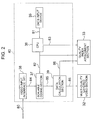
- FIG. 2 is a block diagram showing the manner in which video program data is coded and stored and coded information is stored.
- a data input device 35 inputs data for designating a scalable coding method.
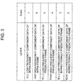
- FIG. 3 shows examples of data inputted from the data input device 35.
- the example of FIG. 3 shows the manner in which pictures of I picture, P picture and B picture are coded by two layers of a low frequency component (L) and a high frequency component (H), and also shows the manner in which flags 7 to 2 are assigned to each layered data.
- a data signal 81 indicative of the number of layers and the flag inputted from the data input device 35 is transmitted through a CPU (central processing unit) 36 to the scalable coding section 37 and the quality index attachment section 33 as layer number data 82.
- Flag data is transmitted to the quality index attachment section 33 as flag data 83.
- the video server 30 receives, at a video input interface (I/F) 38, the analog video signal 80 for encoding by a scalable coding method.
- the video input interface 38 transmits the video program thus received to the scalable coding section 37 as a video program signal 84.
- the scalable coding section 37 encodes the video program signal 84 by the scalable encoding method designated by the aforementioned data input device 35, and transmits the data 85 encoded by the scalable coding to a data calculation section 39.
- the data calculation section 39 calculates a data transmission rate for each layer, and transmits the data transmission rate thus calculated to the quality index attachment section 33 as a data transmission rate information signal 86 of each layer.
- the data calculation section 39 transmits the data 85 encoded by the scalable coding to the multi-quality layered video section 32.
- the multi-quality layered video section 32 stores and holds the data 85 encoded by the scalable coding thus transmitted.
- the quality index attachment section 33 forms combinations of a total data transmission rate of each video quality and flags necessary for realizing the reproduction of each quality from the layer number data 82 inputted from the data input device 35, the flag data 83 and each layer data transmission rate information 86 from the data calculation section 39.
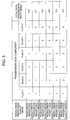
- FIGS. 4 and 5 show tables of flags necessary in respective qualities and total data transmission rates thus formed.
- a study of FIGS. 4 and 5 reveals that two kinds of quality modes of motion prioritized mode and resolution prioritized mode are set in this embodiment.
- motion prioritized quality modes of six stages ranging from a motion prioritized quality mode 1 to a motion prioritized quality mode 6.
- Flags 7 to 2 in FIG. 4 represent low frequency components and high frequency components of respective I, P and B pictures as mentioned before in FIG. 3. While reference numerals 1 are attached to all components from the flags 7 to 2 in the quality of the motion prioritized mode 1, for example, these reference numerals 1 mean that the quality of the motion prioritized mode 1 contains six components of low frequency components and high frequency components of all I, P, B pictures. Also, in the quality of the motion prioritized mode 3, for example, the I picture contains both of the low frequency components and the high frequency components, and the P picture and the B picture contain only the low frequency components.
- a total data transmission rate on the right-hand end column of the table shown in FIG. 4 represents a value which results from accumulating respective layer data transmission rates from the data calculation section 32 in FIG. 2.
- the total data transmission rate for example, there is illustrated the total data transmission rate of 6.0 Mbit/s.
- the total data transmission rate for example, there is illustrated the total data transmission rate of 4.2 Mbit/s.
- the resolution prioritized mode shown in FIG. 5 there are set resolution prioritized quality modes of six stages ranging from the resolution prioritized mode 1 to the resolution prioritized mode 6.
- the flags and the total data transmission rate in FIG. 5 represent meanings similar to those described in FIG. 4. That is, while the quality of the resolution prioritized mode 3 contain the low frequency components and the high frequency components of I and P pictures, the B picture contains neither the low frequency component nor the high frequency component. Also, a total data transmission rate means that there exist data of 5.0 Mbit/s.
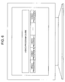
- FIG. 6 shows a state in which examples of video programs that can be selected from the video program guide are displayed on the client terminals 11 and 12. Initially, a viewer selects a desired video program on the video program selection picture shown in FIG. 6. For example, let it be assumed that the client terminals 11 and 12 select a video program A. In this case, the client terminals 11 and 12 issue a serving demand of the video program A to the video server 30.
- the video program serving demands are transmitted through the quality demand control section 21 within the video quality control equipment 20 existing on the network to the data output control section 31 within the video server 30 as the video program serving demand signal 60.
- the quality demand control section 21 stores and holds information of video programs demanded by the video program client terminals 11 and 12 in the internal memory. That is, the video quality control equipment 20 stores and holds information indicating that the video program A is demanded by the client terminals 11 and 12.
- the quality demand control section 21 transmits data indicative of making a duplication to serve video program data to a duplication control section 22 by using a control signal 62. Further, a data distribution control section 23 is controlled by a control signal 63 in such a manner that data duplicated by the duplication control section 22 is served to the client terminals 11 and 12.
- the data output control section 31 within the video server 30 When the data output control section 31 within the video server 30 receives the video program service demand signal 60, the data output control section 31 instructs the quality index attachment section 33, which stores and holds coding information such as flags of respective layers in which video programs are coded and data transmission rates for respective layers, by using a control signal 72 in such a manner that the quality index attachment section 33 outputs coding format information.
- the quality index attachment section 33 receives the coding format information output instruction signal 72 from the data output control section 31, the quality index attachment section 33 transmits the coding format information thus stored and held such as the flags of the respective layers and the data transmission rates of the respective layers, i.e. information described in FIGS. 4 and 5 to the data output section 34 as a coded information signal 74.
- the data output section 34 encapsulates the coding format information received from the quality index attachment section 33 into a packet, and transmits the same to the video quality control equipment 20 as the coding format information signal 61.
- the duplication control section 22 within the video quality control equipment 20 stored and holds the coding format information signal 61 received from the data output section 34, i.e. the coding information such as the flags of the respective quality modes and the data transmission rates of the respective quality modes in the internal memory, duplicates the coding format information, and transmits duplicated coding format information signals 64 and 65 to the data distribution control section 23.
- the data distribution control section 23 transmits the coding format information transmitted from the duplication control section 22 to the client terminals 11 and 12 as the coding format information signals 66 and 67.
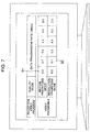
- the client terminals 11 and 12 When the client terminals 11 and 12 receive the coding format information signals 66 and 67, the client terminals 11 and 12 display the picture shown in FIG. 7 on the display screen. Since the user initially demands the service of the video program A, there are displayed a quality mode that can be provided in the video program A and a data transmission rate on the display screen. Then, the user selects a quality mode and a reception data transmission rate corresponding to the video program A shown in FIG. 7.
- the user selects the right-hand side data transmission rate portion on the picture of FIG. 7 displayed on the display screen of the client terminals, i.e. a quality of 6.0 Mbit/s at the motion prioritized quality mode 91 (i.e. "motion prioritized mode 1" in FIG. 4) is selected in the client terminal 11. Also, a quality of 5.7 Mbit/s at the resolution prioritized quality mode 92 (i.e. "resolution prioritized mode 2" in FIG. 5) is selected in the client terminal 12. In this case, the client terminals 11 and 12 issue the video program demands with the selected quality modes to the video server 30 by using the demand signals 51 and 52.
- a video program output instruction is supplied through the quality demand control section 21 within the video quality control equipment 20 existing on the network to the data output control section 31 within the video server 30 as the video program service demand signal 60.
- the quality demand control section 21 stores and holds quality mode information of the video programs demanded by the video program client terminals 11 and 12 in the internal memory.
- the quality demand control section 21 stores and holds the information such that the client terminal 11 ordered the quality mode information indicating that the quality mode video program of 6.0 Mbit/s in the motion prioritized quality mode of the video program A in the internal memory, and the information such that the client terminal 12 ordered the quality mode information indicating that the quality mode video program of 5.7 Mbit/s in the resolution prioritized quality mode of the video program A in the internal memory.
- the quality demand control section 21 transmits the quality information demanded by the video program client terminals 11 and 12 to the duplication control section 22 by using the control signal 62. Further, the quality demand control section 21 controls the data distribution control section 23 by the control signal 63 in such a manner that the data distribution control section 23 may serve data generated by the duplication control section 22 to the client terminals 11 and 12.
- the data output control section 31 within the video server 30 receives the video program service demand signal 60, the data output control section 31 transmits a demanded video program output instruction to the multi-quality layered video section 32 which stores and holds the video program data encoded by the scalable coding method through the control signal 71.
- the multi-quality layered video section 32 receives the video program output demand signal 71 from the data output control section 31, the multi-quality layered video section 32 transmits the stored and held video program data encoded by the scalable coding method to the data output section 34 as the coded data signal 73.
- the data output section 34 encapsulates the layered-coded data received from the multi-quality layered video section 32 into the packet by assigning the flag of each layer, and transmits the resultant packets to the video quality control equipment 20 as the coded data signal 61.
- a system for assigning the flag of each layer there may be used a TOS (Type of Service) field within the header of IP packet when the data encoded by the scalable coding method is encapsulated into the IP packet, for example.
- the duplication control section 22 within the video quality control equipment 20 compares the video program quality modes, demanded by the client terminals 11 and 12, transmitted from the quality demand control section 21 with the coding format information initially received from the video server 30, and forms (duplicates) layered-coded data necessary for serving the video programs of the quality modes demanded by the client terminals 11 and 12 from the received layered-coded data 61.
- the duplication control section 22 duplicates data of packets having the flags 7 to 2 (i.e. all packets), and transmits the data thus duplicated to the data distribution control section 23 as the video program data 64 demanded from the client terminal 11. Accordingly, in this case, the quality mode need not be changed and the received data is transmitted to the data transmission section 23 as the demanded video program data 64 as it is. Also, since the client terminal 12 demands the quality mode of 5.7 Mbit/s in the resolution prioritized mode of the video program A, the duplication control section 22 duplicates data other than data of the high frequency component of the B picture, i.e.
- the data distribution control section 23 transmits the data encoded by the scalable coding method 64 and 65 transmitted from the duplication control section 22 to the client terminals 11 and 12 as the video program service data signals 66 and 67.
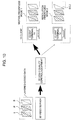
- FIG. 10 illustrates the state in which the video program A is multicast on the client terminal 11 which demands the quality mode of "motion prioritized quality mode 1" selected from the video server 30 and the client terminal 12 which demands the quality mode of "resolution prioritized quality mode 2" selected from the video server 30.
- the high frequency component of the B picture is not transmitted to the client terminal 12.
- the client terminals 11 and 12 receive the video program data signals 66 and 67 outputted from the video quality control equipment 20, and display the video program data thus received on the display screens thereof.
- the display size of video program displayed by the reception terminal has not been described so far, it is possible to automatically set the quality mode of the received video program based on the display size of video program displayed on the client terminal. For example, if the display size of the video program displayed on the client terminal is less than a certain size, it is possible to construct the system in such a manner that the system may automatically receive video program data of the quality modes having only the low frequency components of the I, P, B pictures, i.e. the video program quality of the motion prioritized quality mode 4. Also, the system may be extended even when the client terminal receives a plurality of video programs.
- FIGS. 8 and 9 are respectively pictorial representations showing the manner in which video programs are displayed on the display screen of the client terminal when the client terminal receives a plurality of (two video programs) video programs.
- FIG. 8 shows the manner in which two video programs are received through the coded data signal 66, i.e. a video program 1 denoted by reference numeral 101 is reproduced and displayed on a small window and a video program 2 denoted by reference numeral 102 is reproduced and displayed on a large window.
- the video server 30 may be demanded by the video program demand signal 51 so as to serve video programs in such a manner that a video program which is to be displayed in maximum size may be displayed with a video program quality designated by the user or with the best quality that can be provided and that video programs which are to be displayed in other sizes may be displayed with a quality lower than that of the video program displayed in maximum size or with the lowest quality that can be provided.
- FIG. 9 shows the manner in which a video program denoted by reference numeral 104 is reproduced and displayed on the front window and a video program 1 denoted by reference numeral 103 is reproduced and displayed on the rear window.
- the video server 30 may be demanded by the video program demand signal 51 so as to serve video programs in such a manner that a video program which is to be displayed on the front may be displayed with a video program quality designated by the user or with the best quality that can be provided and that video programs which are to be displayed at other positions may be displayed with a quality lower than that of the video program displayed on the front or with the lowest quality that can be provided.
- a video program which is to be served is layered-coded, the flag is assigned to each layer, and then the video program is served. Also, in order to reproduce video programs with a plurality of quality modes, information indicating a combination of flags for serving data necessary for reproducing video programs with respective quality modes are served together with video programs data. Therefore, there can be achieved the effects to provide the video program transmission and reception system capable of reproducing video programs with a plurality of quality modes from one stream data which results from video programs data encoded by the scalable coding method.
Abstract
A video server encapsulates video program data,
encoded by the scalable coding method, into packets,
assigns a flag to the packet for each layer and transmits
the packet to a video quality control equipment (20)
existing on an edge of a network branching to client
terminals (11 and 12). The video quality control equipment
(20) duplicates and converts video program data, encoded
by the scalable coding method, according to quality modes
demanded from the client terminals (11 and 12), and serves
the video program data thus duplicated and converted to
the respective client terminals (11 and 12).
Description
The present invention relates to a serving
system for serving a video program including video data,
acoustic data or the like, and particularly relates to an
apparatus for encapsulating a broadcasting type video
program into packets and transmitting them.
As a conventional video data transmission
apparatus, there is hitherto known a system for
encapsulating video data into packets for each wavelet
bandwidth as disclosed in JP-A-7-15609 (laid-open on
January 17, 1995). This prior-art technology is intended
to provide video data transmission method and video data
transmission apparatus, video data reception apparatus in
which a video data is transmitted according to a
transmission capability of a network for video data
transmission on a video data reception side and a decoding
performance of a video data reception apparatus even when
the transmission capability of the network for video data
transmission on the video data reception side and the
decoding performance of the video data reception apparatus
are inferior to a transmission capability of a network for
video data transmission on a video data transmission side
and a coding performance of a video data transmission
apparatus. As a system that may be realized in actual
practice, in a video data transmission apparatus, a video
data is encapsulated into packets for each wavelet
bandwidth, a predetermined flag is set for each packet and
a resultant packet is then transmitted. When a network for
transmitting video data is based on the ATM (Asynchronous
Transfer Mode), video data is transmitted with priority
information added to a header of a cell. On a network for
transmitting video data, upon congestion of the network, a
cell with a high priority is preferentially transmitted. A
video data reception apparatus is permitted to reproduce
video data according to a processing ability on the
reception side by selecting and decoding only necessary
video data, according to a decoding performance, based on
a flag of received video data.
On the other hand, as a system for serving video
data by using a network, there is known a multicast system
using an IP (Internet Protocol) network. While the IP
multicast system which serves video data serves same video
data to a plurality of reception apparatus, streams of the
number corresponding to the number of reception apparatus
are not served from a video data serving apparatus but the
video stream branches to a necessary number at a tree-like
branching point in the network, thereby resulting in the
same video data being served to a plurality of reception
apparatus. Specifically, when there are provided two video
data reception apparatus as shown in FIG. 11, two video
data streams are not served from a video data server as a
transmission apparatus but a video data stream is
duplicated at an edge router on a network where the
network finally branching to the two client terminals,
thereby resulting in the same video data stream being
served to the two client terminals as reception apparatus.
The video data is transmitted as described above, whereby
a limited transmission capacity of the network may be
utilized effectively.
JP-A-4-003684 (laid-open on January 8, 1992)
discloses an apparatus for encoding a motion picture with
a variable rate for use in a videophone, video conference
or the like.
JP-A-9-116551 (laid-open on May 2, 1997)
discloses a data packet transmission method and apparatus
in which data packets are transmitted/received through an
ATM network.
JP-A-10-023418 (laid-open on January 23, 1998),
JP-A-9-247676 (laid-open on September 19, 1997) and JP-A-10-032608
(laid-open on February 3, 1998) disclose a
packet video rate conversion apparatus, which is
particularly adapted for video conference communication
over a network.
However, when the above-described conventional
technology is applied to a video program service system,
the following inconveniences may be encounted.
When video data is wavelet-coded and transmitted,
the video transmission apparatus, according to JP-A-7-15609
assigns a flag to a data transmitting packet for
each band and transmits resultant data, the reception
apparatus decodes and reproduces only data having a packet
with a necessary flag based on a reproduction capability.
For example, let us assume a video program service system
in which the charging is graded by a level of reproduction
quality (picture quality, smoothness of motion, etc.) of
video data. Even when a reception apparatus has a video
data reproduction capability high enough to reproduce full
data transmitted from the video program service system, a
viewer may not desire such a high reproduction quality. In
such a case, it is desired that video data should be
reproduced with a reproduction quality which meets with
viewer's requirements, in addition to the processing
capability of the reception apparatus. However,
conventionally, the reproduction quality of video data
depended upon only the processing capability of the
reception apparatus and the video data could not be
reproduced with the reproduction quality which meets with
viewer's requirements.
Next, when there are provided a plurality of
video program reception apparatus, according to the
conventional IP multicast system, video data is duplicated
at a branching point, and the same video data is served to
a plurality of reception apparatus. Therefore, the
conventional IP multicast system may not be able to serve
video programs with different qualities to a plurality of
video program reception apparatus. Moreover, according to
the conventional IP multicast system, when a plurality of
video program reception apparatus demand to transmit the
same video program with different reproduction qualities,
video data of the same quality, in other words, video data
of the same data transmission rate is transmitted to a
plurality of video program reception apparatus. As a
result, a plurality of video program reception apparatus
cannot reproduce a video program with different quality
levels depending on viewer's requests.
Therefore, an object of the present invention is
to provide a video program transmission and reception
system in which a video program with a plurality of
qualities can be reproduced from one video stream when a
video program is transmitted from a video server for
reproduction.
It is another object of the present invention to
provide a video program transmission and reception system
in which, when there are provided a plurality of video
program reception apparatus, a video stream with a
necessary quality is duplicated by an edge router at edges
branching to the plurality of reception apparatus on the
network and served thereto.
According to an aspect of the present invention,
in a video program service system, an outputted video
program is layered-coded, layered-coded video and acoustic
data are stored and held in a video server as a video
program output apparatus, the layered-coded data are
encapsulated into packets for service, a flag is assigned
to the to-be-served packets for each layer and resultant
packets are transmitted. Further, a data rate of the
layered-coded data is measured for each layer, a program
data rate of each to-be-served video program quality is
calculated and stored in the video program output
apparatus, and information on relation between the video
data rate for each to-be-served video program quality and
the flag of the packet for transmitting the data necessary
for reproducing each to-be-served video program quality is
transmitted similarly to the above-described video data.
According to another aspect of the present
invention, in a video program reception apparatus, a
received video program quality is demanded and a quality
of a to-be-received video program is designated.
According to another aspect of the present
invention, in a reception apparatus, picture sizes of a
plurality of displayed video programs are designated and
displayed individually, and a video program which is
displayed in maximum size among a plurality of displayed
video programs is demanded to be served with a high
quality so that video programs of sizes other than the
maximum size are demanded to be served with a low quality.
According to another aspect of the present
invention, in a reception apparatus, display positions of
a plurality of displayed video programs are designated and
displayed individually, a video program which is displayed
on the front plane among a plurality of displayed video
programs is demanded to be served with a high quality, and
video programs displayed on planes other than the front
plane are demanded to be served with a low quality.
An embodiment according to the present invention
will hereinafter be described with reference to the
drawings. FIG. 1 of the accompanying drawings is a block
diagram showing a multi-quality layered video service
system according to an embodiment of the present invention.
As shown in FIG. 1, the multi-quality layered
video service system according to the present invention
comprises a video server 30 for serving a video program
composed of video and audio data or the like, a video
quality control equipment 20 capable of changing a quality
of video program on the network and a client 10 for
receiving and reproducing a video program based on a video
program demand. More in detail, the video server 30
comprises an encoding section 40 for encoding an analog
video program, a data output control section 31 for
controlling the data output, a multi-quality layered video
section 32 for storing and holding coded program data, a
quality index attachment section 33 and a data output
section 34. Also, the video quality control equipment 20
comprises a quality demand control section 21, a
duplication control section 22 and a data distribution
control section 23. Further, the client 10 comprises a
plurality of client terminals. In this embodiment, a
plurality of client terminals assume two client terminals.
In this assumption, an operation of a multi-quality
layered video service system according to the embodiment
of the present invention will be described hereinafter.
The multi-quality layered video service system
shown in FIG. 1 is a system for serving the same video
program based on video program output demands from one or
a plurality of clients 10. In the video server 30,
initially, the encoding section 40 encodes the analog
video program by a scalable coding method, the multi-quality
layered video section 32 stores and holds layered-coded
video program data, and the quality index attachment
section 33 stores and holds coded information such as a
flag for identifying each layer and a data transmission
rate of each layer.
FIG. 2 is a block diagram showing the manner in
which video program data is coded and stored and coded
information is stored. In the encoding section 40 shown in
FIG. 2, initially, a data input device 35 inputs data for
designating a scalable coding method.
FIG. 3 shows examples of data inputted from the
data input device 35. The example of FIG. 3 shows the
manner in which pictures of I picture, P picture and B
picture are coded by two layers of a low frequency
component (L) and a high frequency component (H), and also
shows the manner in which flags 7 to 2 are assigned to
each layered data. As shown in FIG. 2, a data signal 81
indicative of the number of layers and the flag inputted
from the data input device 35 is transmitted through a CPU
(central processing unit) 36 to the scalable coding
section 37 and the quality index attachment section 33 as
layer number data 82. Flag data is transmitted to the
quality index attachment section 33 as flag data 83. After
the layer number is set in the scalable coding section 37,
the video server 30 receives, at a video input interface
(I/F) 38, the analog video signal 80 for encoding by a
scalable coding method. The video input interface 38
transmits the video program thus received to the scalable
coding section 37 as a video program signal 84. The
scalable coding section 37 encodes the video program
signal 84 by the scalable encoding method designated by
the aforementioned data input device 35, and transmits the
data 85 encoded by the scalable coding to a data
calculation section 39. The data calculation section 39
calculates a data transmission rate for each layer, and
transmits the data transmission rate thus calculated to
the quality index attachment section 33 as a data
transmission rate information signal 86 of each layer.
Also, the data calculation section 39 transmits the data
85 encoded by the scalable coding to the multi-quality
layered video section 32. The multi-quality layered video
section 32 stores and holds the data 85 encoded by the
scalable coding thus transmitted. The quality index
attachment section 33 forms combinations of a total data
transmission rate of each video quality and flags
necessary for realizing the reproduction of each quality
from the layer number data 82 inputted from the data input
device 35, the flag data 83 and each layer data
transmission rate information 86 from the data calculation
section 39.
FIGS. 4 and 5 show tables of flags necessary in
respective qualities and total data transmission rates
thus formed. A study of FIGS. 4 and 5 reveals that two
kinds of quality modes of motion prioritized mode and
resolution prioritized mode are set in this embodiment.
In the motion prioritized mode shown in FIG. 4,
there are set motion prioritized quality modes of six
stages ranging from a motion prioritized quality mode 1 to
a motion prioritized quality mode 6. Flags 7 to 2 in FIG.
4 represent low frequency components and high frequency
components of respective I, P and B pictures as mentioned
before in FIG. 3. While reference numerals 1 are attached
to all components from the flags 7 to 2 in the quality of
the motion prioritized mode 1, for example, these
reference numerals 1 mean that the quality of the motion
prioritized mode 1 contains six components of low
frequency components and high frequency components of all
I, P, B pictures. Also, in the quality of the motion
prioritized mode 3, for example, the I picture contains
both of the low frequency components and the high
frequency components, and the P picture and the B picture
contain only the low frequency components. A total data
transmission rate on the right-hand end column of the
table shown in FIG. 4 represents a value which results
from accumulating respective layer data transmission rates
from the data calculation section 32 in FIG. 2. In the
quality of the motion prioritized mode 1, for example,
there is illustrated the total data transmission rate of
6.0 Mbit/s. In the quality of the motion prioritized mode
4, for example, there is illustrated the total data
transmission rate of 4.2 Mbit/s.
In the resolution prioritized mode shown in FIG.
5, there are set resolution prioritized quality modes of
six stages ranging from the resolution prioritized mode 1
to the resolution prioritized mode 6. The flags and the
total data transmission rate in FIG. 5 represent meanings
similar to those described in FIG. 4. That is, while the
quality of the resolution prioritized mode 3 contain the
low frequency components and the high frequency components
of I and P pictures, the B picture contains neither the
low frequency component nor the high frequency component.
Also, a total data transmission rate means that there
exist data of 5.0 Mbit/s.
Next, the manner in which video programs are
served in response to video program serving demands from
the two client terminals will be described with reference
to FIG. 1.
Initially, the video program client terminals 11
and 12 issue desired video program serving demands to the
video server 30 by using the video program serving demand
signals 51, 52. FIG. 6 shows a state in which examples of
video programs that can be selected from the video program
guide are displayed on the client terminals 11 and 12.
Initially, a viewer selects a desired video program on the
video program selection picture shown in FIG. 6. For
example, let it be assumed that the client terminals 11
and 12 select a video program A. In this case, the client
terminals 11 and 12 issue a serving demand of the video
program A to the video server 30. When the video program
client terminals 11 and 12 issue the video program serving
demands to the video server 30, the video program serving
demands are transmitted through the quality demand control
section 21 within the video quality control equipment 20
existing on the network to the data output control section
31 within the video server 30 as the video program serving
demand signal 60. The quality demand control section 21
stores and holds information of video programs demanded by
the video program client terminals 11 and 12 in the
internal memory. That is, the video quality control
equipment 20 stores and holds information indicating that
the video program A is demanded by the client terminals 11
and 12. The quality demand control section 21 transmits
data indicative of making a duplication to serve video
program data to a duplication control section 22 by using
a control signal 62. Further, a data distribution control
section 23 is controlled by a control signal 63 in such a
manner that data duplicated by the duplication control
section 22 is served to the client terminals 11 and 12.
When the data output control section 31 within
the video server 30 receives the video program service
demand signal 60, the data output control section 31
instructs the quality index attachment section 33, which
stores and holds coding information such as flags of
respective layers in which video programs are coded and
data transmission rates for respective layers, by using a
control signal 72 in such a manner that the quality index
attachment section 33 outputs coding format information.
When the quality index attachment section 33 receives the
coding format information output instruction signal 72
from the data output control section 31, the quality index
attachment section 33 transmits the coding format
information thus stored and held such as the flags of the
respective layers and the data transmission rates of the
respective layers, i.e. information described in FIGS. 4
and 5 to the data output section 34 as a coded information
signal 74. The data output section 34 encapsulates the
coding format information received from the quality index
attachment section 33 into a packet, and transmits the
same to the video quality control equipment 20 as the
coding format information signal 61. The duplication
control section 22 within the video quality control
equipment 20 stored and holds the coding format
information signal 61 received from the data output
section 34, i.e. the coding information such as the flags
of the respective quality modes and the data transmission
rates of the respective quality modes in the internal
memory, duplicates the coding format information, and
transmits duplicated coding format information signals 64
and 65 to the data distribution control section 23. The
data distribution control section 23 transmits the coding
format information transmitted from the duplication
control section 22 to the client terminals 11 and 12 as
the coding format information signals 66 and 67.
When the client terminals 11 and 12 receive the
coding format information signals 66 and 67, the client
terminals 11 and 12 display the picture shown in FIG. 7 on
the display screen. Since the user initially demands the
service of the video program A, there are displayed a
quality mode that can be provided in the video program A
and a data transmission rate on the display screen. Then,
the user selects a quality mode and a reception data
transmission rate corresponding to the video program A
shown in FIG. 7.
In actual practice, the user selects the right-hand
side data transmission rate portion on the picture of
FIG. 7 displayed on the display screen of the client
terminals, i.e. a quality of 6.0 Mbit/s at the motion
prioritized quality mode 91 (i.e. "motion prioritized mode
1" in FIG. 4) is selected in the client terminal 11. Also,
a quality of 5.7 Mbit/s at the resolution prioritized
quality mode 92 (i.e. "resolution prioritized mode 2" in
FIG. 5) is selected in the client terminal 12. In this
case, the client terminals 11 and 12 issue the video
program demands with the selected quality modes to the
video server 30 by using the demand signals 51 and 52.
When the client terminals 11 and 12 issue the
video program demands with the quality modes selected by
the respective client terminals 11 and 12 to the video
server 30, a video program output instruction is supplied
through the quality demand control section 21 within the
video quality control equipment 20 existing on the network
to the data output control section 31 within the video
server 30 as the video program service demand signal 60.
The quality demand control section 21 stores and holds
quality mode information of the video programs demanded by
the video program client terminals 11 and 12 in the
internal memory. The quality demand control section 21
stores and holds the information such that the client
terminal 11 ordered the quality mode information
indicating that the quality mode video program of 6.0
Mbit/s in the motion prioritized quality mode of the video
program A in the internal memory, and the information such
that the client terminal 12 ordered the quality mode
information indicating that the quality mode video program
of 5.7 Mbit/s in the resolution prioritized quality mode
of the video program A in the internal memory.
Also, the quality demand control section 21
transmits the quality information demanded by the video
program client terminals 11 and 12 to the duplication
control section 22 by using the control signal 62. Further,
the quality demand control section 21 controls the data
distribution control section 23 by the control signal 63
in such a manner that the data distribution control
section 23 may serve data generated by the duplication
control section 22 to the client terminals 11 and 12.
When the data output control section 31 within
the video server 30 receives the video program service
demand signal 60, the data output control section 31
transmits a demanded video program output instruction to
the multi-quality layered video section 32 which stores
and holds the video program data encoded by the scalable
coding method through the control signal 71. When the
multi-quality layered video section 32 receives the video
program output demand signal 71 from the data output
control section 31, the multi-quality layered video
section 32 transmits the stored and held video program
data encoded by the scalable coding method to the data
output section 34 as the coded data signal 73. The data
output section 34 encapsulates the layered-coded data
received from the multi-quality layered video section 32
into the packet by assigning the flag of each layer, and
transmits the resultant packets to the video quality
control equipment 20 as the coded data signal 61.
Incidentally, as a system for assigning the flag of each
layer, there may be used a TOS (Type of Service) field
within the header of IP packet when the data encoded by
the scalable coding method is encapsulated into the IP
packet, for example.
The duplication control section 22 within the
video quality control equipment 20 compares the video
program quality modes, demanded by the client terminals 11
and 12, transmitted from the quality demand control
section 21 with the coding format information initially
received from the video server 30, and forms (duplicates)
layered-coded data necessary for serving the video
programs of the quality modes demanded by the client
terminals 11 and 12 from the received layered-coded data
61.
In this embodiment, since the client terminal 11
demands the quality mode of 6.0 Mbit/s in the motion
prioritized quality mode of the video program A, the
duplication control section 22 duplicates data of packets
having the flags 7 to 2 (i.e. all packets), and transmits
the data thus duplicated to the data distribution control
section 23 as the video program data 64 demanded from the
client terminal 11. Accordingly, in this case, the quality
mode need not be changed and the received data is
transmitted to the data transmission section 23 as the
demanded video program data 64 as it is. Also, since the
client terminal 12 demands the quality mode of 5.7 Mbit/s
in the resolution prioritized mode of the video program A,
the duplication control section 22 duplicates data other
than data of the high frequency component of the B picture,
i.e. data except the packet having the flag 2 from the
received data encoded by the scalable coding method 61,
and transmits the data thus duplicated to the data
distribution control section 23 as the video program data
demanded from the client terminal 12. The data
distribution control section 23 transmits the data encoded
by the scalable coding method 64 and 65 transmitted from
the duplication control section 22 to the client terminals
11 and 12 as the video program service data signals 66 and
67.
FIG. 10 illustrates the state in which the video
program A is multicast on the client terminal 11 which
demands the quality mode of "motion prioritized quality
mode 1" selected from the video server 30 and the client
terminal 12 which demands the quality mode of "resolution
prioritized quality mode 2" selected from the video server
30. As described above, the high frequency component of
the B picture is not transmitted to the client terminal 12.
The client terminals 11 and 12 receive the video program
data signals 66 and 67 outputted from the video quality
control equipment 20, and display the video program data
thus received on the display screens thereof.
While the display size of video program
displayed by the reception terminal has not been described
so far, it is possible to automatically set the quality
mode of the received video program based on the display
size of video program displayed on the client terminal.
For example, if the display size of the video program
displayed on the client terminal is less than a certain
size, it is possible to construct the system in such a
manner that the system may automatically receive video
program data of the quality modes having only the low
frequency components of the I, P, B pictures, i.e. the
video program quality of the motion prioritized quality
mode 4. Also, the system may be extended even when the
client terminal receives a plurality of video programs.
FIGS. 8 and 9 are respectively pictorial
representations showing the manner in which video programs
are displayed on the display screen of the client terminal
when the client terminal receives a plurality of (two
video programs) video programs.
FIG. 8 shows the manner in which two video
programs are received through the coded data signal 66,
i.e. a video program 1 denoted by reference numeral 101 is
reproduced and displayed on a small window and a video
program 2 denoted by reference numeral 102 is reproduced
and displayed on a large window. When the display sizes of
the received video programs are different as described
above, the video server 30 may be demanded by the video
program demand signal 51 so as to serve video programs in
such a manner that a video program which is to be
displayed in maximum size may be displayed with a video
program quality designated by the user or with the best
quality that can be provided and that video programs which
are to be displayed in other sizes may be displayed with a
quality lower than that of the video program displayed in
maximum size or with the lowest quality that can be
provided.
FIG. 9 shows the manner in which a video program
denoted by reference numeral 104 is reproduced and
displayed on the front window and a video program 1
denoted by reference numeral 103 is reproduced and
displayed on the rear window. When the displayed positions
of the received video programs on the display screen are
different as described above, the video server 30 may be
demanded by the video program demand signal 51 so as to
serve video programs in such a manner that a video program
which is to be displayed on the front may be displayed
with a video program quality designated by the user or
with the best quality that can be provided and that video
programs which are to be displayed at other positions may
be displayed with a quality lower than that of the video
program displayed on the front or with the lowest quality
that can be provided.
As described above, according to the multi-quality
layered video service system in one aspect of the
present invention, a video program which is to be served
is layered-coded, the flag is assigned to each layer, and
then the video program is served. Also, in order to
reproduce video programs with a plurality of quality modes,
information indicating a combination of flags for serving
data necessary for reproducing video programs with
respective quality modes are served together with video
programs data. Therefore, there can be achieved the
effects to provide the video program transmission and
reception system capable of reproducing video programs
with a plurality of quality modes from one stream data
which results from video programs data encoded by the
scalable coding method.
Having described a preferred embodiment of the
invention with reference to the accompanying drawings, it
is to be understood that the invention is not limited to
that precise embodiment and that various changes and
modifications could be effected therein by one skilled in
the art without departing from the spirit or scope of the
invention as defined in the appended claims.
Claims (9)
- A video program serving system comprising:a video server (30); anda video quality control equipment (20) connected to said video server (30) and a plurality of client terminals (11, 12) through a network, wherein said video server (30) includes means (34) for encapsulating video data, encoded by a scalable coding method, into packets and outputting said packet with a flag for each layer, and said video quality control equipment (20) includes means (22) for duplicating data, which results from combining encoded data of different layers, from one video data, encoded by the scalable coding method, received from said video server (30) and for transmitting it for each client terminal.
- A video program serving system according to claim 1, wherein said video server (30) includes means (33) for measuring a combination of said flags and data transmission rates of encoded data corresponding to said combination and means (34) for transmitting information concerning said measured data transmission rate through said video quality control equipment (20) to a client terminal (11, 12).
- A video server (30) comprising:means (34) for encapsulating video data, encoded by a scalable coding method, into packets and outputting said packet with a flag assigned for each layer; andmeans (33) for encapsulating information concerning a combination of flags and a data transmission rate of data, encoded by the scalable coding method, corresponding to said combination into packets and outputting said packets.
- A video server (30) according to claim 3, further comprising means (40) for measuring a data transmission rate for each layer of said video data encoded by the scalable coding method.
- A video quality control equipment (20) comprising:means (22) for duplicating video programs of quality different for each client terminal (11, 12), from one video data, encoded by a scalable coding method, received from a video server (30) and serving said duplicated video programs.
- A video quality control equipment (20) according to claim 5, further comprising means (22) for duplicating data which results from combining encoded data of different layers for each client terminal (11, 12), from one video data, encoded by the scalable coding method, received from a video server (30) and transmitting said duplicated data.
- A video program receiving apparatus (10) comprising:means (11, 12) for receiving information concerning a data transmission rate obtained when a video program transmitted from a video server (30) is displayed with a first quality mode and information concerning a data transmission rate obtained when said video program is displayed with a second quality mode lower than said first quality mode and displaying said information on a display screen; andmeans for selecting said first quality mode and said second quality mode from said display screen.
- A video program receiving apparatus according to claim 7, further comprising:means (11, 12) for receiving first and second video programs from said video server (30) through a network and displaying said first and second video programs on said display screen in a multi-window fashion; andmeans for demanding that said first video program is served with said first quality mode and said second video program is served with said second quality mode when a window size for displaying said first video program is larger than a window size for displaying said second video program.
- A video program receiving apparatus according to claim 7, further comprising:means (11, 12) for receiving first and second video programs from a video server (30) through a network and displaying said first and second video programs on said display screen in a multi-window fashion; andmeans for demanding that said first video program is served with said first quality mode and said second video program is served with said second quality mode when a window for displaying said first video program is located ahead of a window for displaying said second video program.
Applications Claiming Priority (2)
| Application Number | Priority Date | Filing Date | Title |
|---|---|---|---|
| JP4673698 | 1998-02-27 | ||
| JP4673698 | 1998-02-27 |
Publications (1)
| Publication Number | Publication Date |
|---|---|
| EP0939545A2 true EP0939545A2 (en) | 1999-09-01 |
Family
ID=12755626
Family Applications (1)
| Application Number | Title | Priority Date | Filing Date |
|---|---|---|---|
| EP99103115A Withdrawn EP0939545A2 (en) | 1998-02-27 | 1999-02-17 | Video service system |
Country Status (1)
| Country | Link |
|---|---|
| EP (1) | EP0939545A2 (en) |
Cited By (12)
| Publication number | Priority date | Publication date | Assignee | Title |
|---|---|---|---|---|
| WO2002019697A2 (en) * | 2000-08-29 | 2002-03-07 | Koninklijke Philips Electronics N.V. | System and method for dynamic adaptive decoding of scalable video to balance cpu load |
| WO2002019095A2 (en) * | 2000-08-29 | 2002-03-07 | Koninklijke Philips Electronics N.V. | Method of running an algorithm and a scalable programmable processing device |
| WO2002032147A1 (en) * | 2000-10-11 | 2002-04-18 | Koninklijke Philips Electronics N.V. | Scalable coding of multi-media objects |
| WO2003046756A2 (en) * | 2001-11-26 | 2003-06-05 | Interuniversitair Microelektronica Centrum Vzw | Schema, syntactic analysis method and method of generating a bit stream based on a schema |
| WO2003077562A1 (en) * | 2002-03-08 | 2003-09-18 | Koninklijke Philips Electronics N.V. | Quality of video |
| FR2902266A1 (en) * | 2006-06-13 | 2007-12-14 | Canon Kk | METHOD AND DEVICE FOR DISTRIBUTING THE COMMUNICATION BANDWIDTH |
| US7366241B2 (en) | 2001-03-29 | 2008-04-29 | Matsushita Electric Industrial Co., Ltd. | Data reproduction apparatus and data reproduction method |
| US7573877B2 (en) * | 2002-04-17 | 2009-08-11 | Sony Corporation | Terminal apparatus, data transmitting apparatus, data transmitting and receiving system, and data transmitting and receiving method |
| US7761901B2 (en) | 2003-03-19 | 2010-07-20 | British Telecommunications Plc | Data transmission |
| US7974200B2 (en) | 2000-11-29 | 2011-07-05 | British Telecommunications Public Limited Company | Transmitting and receiving real-time data |
| US8135852B2 (en) | 2002-03-27 | 2012-03-13 | British Telecommunications Public Limited Company | Data streaming system and method |
| EP1589435B1 (en) * | 2003-01-29 | 2021-07-14 | Sony Corporation | Information processing device, information processing method, and computer program |
-
1999
- 1999-02-17 EP EP99103115A patent/EP0939545A2/en not_active Withdrawn
Cited By (20)
| Publication number | Priority date | Publication date | Assignee | Title |
|---|---|---|---|---|
| WO2002019095A2 (en) * | 2000-08-29 | 2002-03-07 | Koninklijke Philips Electronics N.V. | Method of running an algorithm and a scalable programmable processing device |
| WO2002019095A3 (en) * | 2000-08-29 | 2002-06-13 | Koninkl Philips Electronics Nv | Method of running an algorithm and a scalable programmable processing device |
| WO2002019697A3 (en) * | 2000-08-29 | 2002-07-11 | Koninkl Philips Electronics Nv | System and method for dynamic adaptive decoding of scalable video to balance cpu load |
| WO2002019697A2 (en) * | 2000-08-29 | 2002-03-07 | Koninklijke Philips Electronics N.V. | System and method for dynamic adaptive decoding of scalable video to balance cpu load |
| WO2002032147A1 (en) * | 2000-10-11 | 2002-04-18 | Koninklijke Philips Electronics N.V. | Scalable coding of multi-media objects |
| US8374344B2 (en) | 2000-10-11 | 2013-02-12 | Koninklijke Philips Electronics N.V. | Coding |
| KR100887165B1 (en) * | 2000-10-11 | 2009-03-10 | 코닌클리케 필립스 일렉트로닉스 엔.브이. | A method and a device of coding a multi-media object, a method for controlling and receiving a bit-stream, a controller for controlling the bit-stream, and a receiver for receiving the bit-stream, and a multiplexer |
| US7974200B2 (en) | 2000-11-29 | 2011-07-05 | British Telecommunications Public Limited Company | Transmitting and receiving real-time data |
| US7366241B2 (en) | 2001-03-29 | 2008-04-29 | Matsushita Electric Industrial Co., Ltd. | Data reproduction apparatus and data reproduction method |
| WO2003046756A2 (en) * | 2001-11-26 | 2003-06-05 | Interuniversitair Microelektronica Centrum Vzw | Schema, syntactic analysis method and method of generating a bit stream based on a schema |
| US7570180B2 (en) | 2001-11-26 | 2009-08-04 | Koninklijke Philips Electronics N.V. | Method for syntactically analyzing a bit stream using a schema and a method of generating a bit stream based thereon |
| WO2003046756A3 (en) * | 2001-11-26 | 2003-12-18 | Imec Inter Uni Micro Electr | Schema, syntactic analysis method and method of generating a bit stream based on a schema |
| WO2003077562A1 (en) * | 2002-03-08 | 2003-09-18 | Koninklijke Philips Electronics N.V. | Quality of video |
| US8135852B2 (en) | 2002-03-27 | 2012-03-13 | British Telecommunications Public Limited Company | Data streaming system and method |
| US8386631B2 (en) | 2002-03-27 | 2013-02-26 | British Telecommunications Plc | Data streaming system and method |
| US7573877B2 (en) * | 2002-04-17 | 2009-08-11 | Sony Corporation | Terminal apparatus, data transmitting apparatus, data transmitting and receiving system, and data transmitting and receiving method |
| EP1589435B1 (en) * | 2003-01-29 | 2021-07-14 | Sony Corporation | Information processing device, information processing method, and computer program |
| US7761901B2 (en) | 2003-03-19 | 2010-07-20 | British Telecommunications Plc | Data transmission |
| FR2902266A1 (en) * | 2006-06-13 | 2007-12-14 | Canon Kk | METHOD AND DEVICE FOR DISTRIBUTING THE COMMUNICATION BANDWIDTH |
| US8510458B2 (en) | 2006-06-13 | 2013-08-13 | Canon Kabushiki Kaisha | Method and device for sharing bandwidth of a communication network |
Similar Documents
| Publication | Publication Date | Title |
|---|---|---|
| JP5304213B2 (en) | Data processing apparatus, program and method, and network system | |
| US11750871B2 (en) | Edge optimized transrating system | |
| US5570126A (en) | System for composing multimedia signals for interactive television services | |
| EP2919453B1 (en) | Video stream switching | |
| JP4552290B2 (en) | Data transmission apparatus and method, data processing apparatus and method | |
| US7639882B2 (en) | Moving picture distribution system, moving picture distribution device and method, recording medium, and program | |
| CN102342066B (en) | Real-time multi-media streaming processing bandwidth management | |
| JPH09163362A (en) | Software-based encoder for software-executed inter-terminal scalable video delivery system | |
| US9392303B2 (en) | Dynamic encoding of multiple video image streams to a single video stream based on user input | |
| EP0939545A2 (en) | Video service system | |
| JP3931531B2 (en) | Hierarchical coded video distribution system | |
| JPH11313301A (en) | Program distribution system, program distributor, program quality converter and program receiver | |
| JP2005538651A (en) | Video on demand server system and method | |
| US20070223635A1 (en) | Information Delivery System and Method, its Information Delivery Apparatus, Receiving Terminal, and Information Relay Apparatus | |
| US9319719B2 (en) | Method for processing video and/or audio signals | |
| US20020174437A1 (en) | Method and apparatus for controlling image quality by culling transmitted image information | |
| JP2823571B2 (en) | Distributed multipoint teleconferencing equipment | |
| JP2002084238A (en) | Multiplex broadcast method and apparatus | |
| US20040146011A1 (en) | Stream for a desired quality level | |
| EA004380B1 (en) | Universal digital broadcast system and methods | |
| JPH11238019A (en) | Data transmission device, data reception device and data conversion device | |
| Nicolaou | ATM based video and audio codecs | |
| KR20050047228A (en) | Mutlticasting serivce method of high density internet broadcast system | |
| Campbell et al. | A dynamic QoS management scheme for adaptive digital video flows |
Legal Events
| Date | Code | Title | Description |
|---|---|---|---|
| PUAI | Public reference made under article 153(3) epc to a published international application that has entered the european phase |
Free format text: ORIGINAL CODE: 0009012 |
|
| AK | Designated contracting states |
Kind code of ref document: A2 Designated state(s): AT BE CH CY DE DK ES FI FR GB GR IE IT LI LU MC NL PT SE |
|
| AX | Request for extension of the european patent |
Free format text: AL;LT;LV;MK;RO;SI |
|
| STAA | Information on the status of an ep patent application or granted ep patent |
Free format text: STATUS: THE APPLICATION IS DEEMED TO BE WITHDRAWN |
|
| 18D | Application deemed to be withdrawn |
Effective date: 20030831 |