EP0940557A2 - Electrically insulating gap subassembly - Google Patents
Electrically insulating gap subassembly Download PDFInfo
- Publication number
- EP0940557A2 EP0940557A2 EP99301634A EP99301634A EP0940557A2 EP 0940557 A2 EP0940557 A2 EP 0940557A2 EP 99301634 A EP99301634 A EP 99301634A EP 99301634 A EP99301634 A EP 99301634A EP 0940557 A2 EP0940557 A2 EP 0940557A2
- Authority
- EP
- European Patent Office
- Prior art keywords
- subassembly
- threaded end
- isolation
- electrically insulating
- isolation subassembly
- Prior art date
- Legal status (The legal status is an assumption and is not a legal conclusion. Google has not performed a legal analysis and makes no representation as to the accuracy of the status listed.)
- Withdrawn
Links
- 238000002955 isolation Methods 0.000 claims abstract description 107
- XAGFODPZIPBFFR-UHFFFAOYSA-N aluminium Chemical compound [Al] XAGFODPZIPBFFR-UHFFFAOYSA-N 0.000 claims abstract description 13
- 229910052782 aluminium Inorganic materials 0.000 claims abstract description 13
- 238000000034 method Methods 0.000 claims description 20
- 239000012777 electrically insulating material Substances 0.000 claims description 9
- 238000001816 cooling Methods 0.000 claims description 2
- 230000008878 coupling Effects 0.000 claims description 2
- 238000010168 coupling process Methods 0.000 claims description 2
- 238000005859 coupling reaction Methods 0.000 claims description 2
- 238000010438 heat treatment Methods 0.000 claims description 2
- 238000005553 drilling Methods 0.000 description 19
- 230000005540 biological transmission Effects 0.000 description 12
- 239000011248 coating agent Substances 0.000 description 12
- 238000000576 coating method Methods 0.000 description 12
- 239000003989 dielectric material Substances 0.000 description 9
- 238000004891 communication Methods 0.000 description 7
- 230000015572 biosynthetic process Effects 0.000 description 6
- 239000000919 ceramic Substances 0.000 description 5
- 238000005259 measurement Methods 0.000 description 5
- 229910000831 Steel Inorganic materials 0.000 description 4
- 239000004020 conductor Substances 0.000 description 4
- 239000011152 fibreglass Substances 0.000 description 4
- 239000011810 insulating material Substances 0.000 description 4
- TWNQGVIAIRXVLR-UHFFFAOYSA-N oxo(oxoalumanyloxy)alumane Chemical compound O=[Al]O[Al]=O TWNQGVIAIRXVLR-UHFFFAOYSA-N 0.000 description 4
- 239000010959 steel Substances 0.000 description 4
- 239000004809 Teflon Substances 0.000 description 3
- 229920006362 Teflon® Polymers 0.000 description 3
- 239000004593 Epoxy Substances 0.000 description 2
- 238000005260 corrosion Methods 0.000 description 2
- 230000007797 corrosion Effects 0.000 description 2
- 238000001514 detection method Methods 0.000 description 2
- 230000005684 electric field Effects 0.000 description 2
- 239000012530 fluid Substances 0.000 description 2
- 229930195733 hydrocarbon Natural products 0.000 description 2
- 150000002430 hydrocarbons Chemical class 0.000 description 2
- 238000009434 installation Methods 0.000 description 2
- 230000008569 process Effects 0.000 description 2
- 239000011347 resin Substances 0.000 description 2
- 229920005989 resin Polymers 0.000 description 2
- 238000006748 scratching Methods 0.000 description 2
- 230000002393 scratching effect Effects 0.000 description 2
- 239000004215 Carbon black (E152) Substances 0.000 description 1
- WHXSMMKQMYFTQS-UHFFFAOYSA-N Lithium Chemical compound [Li] WHXSMMKQMYFTQS-UHFFFAOYSA-N 0.000 description 1
- 230000002159 abnormal effect Effects 0.000 description 1
- 230000005534 acoustic noise Effects 0.000 description 1
- 230000009471 action Effects 0.000 description 1
- OJIJEKBXJYRIBZ-UHFFFAOYSA-N cadmium nickel Chemical compound [Ni].[Cd] OJIJEKBXJYRIBZ-UHFFFAOYSA-N 0.000 description 1
- 150000001875 compounds Chemical class 0.000 description 1
- 238000012937 correction Methods 0.000 description 1
- 230000001934 delay Effects 0.000 description 1
- 230000001419 dependent effect Effects 0.000 description 1
- 238000010292 electrical insulation Methods 0.000 description 1
- 230000008030 elimination Effects 0.000 description 1
- 238000003379 elimination reaction Methods 0.000 description 1
- 230000007613 environmental effect Effects 0.000 description 1
- 230000006870 function Effects 0.000 description 1
- 239000003292 glue Substances 0.000 description 1
- 238000009413 insulation Methods 0.000 description 1
- 229910052744 lithium Inorganic materials 0.000 description 1
- 238000004519 manufacturing process Methods 0.000 description 1
- 239000000463 material Substances 0.000 description 1
- 230000007246 mechanism Effects 0.000 description 1
- 239000000203 mixture Substances 0.000 description 1
- 238000012544 monitoring process Methods 0.000 description 1
- 239000000615 nonconductor Substances 0.000 description 1
- 230000035515 penetration Effects 0.000 description 1
- 239000004033 plastic Substances 0.000 description 1
- 238000012545 processing Methods 0.000 description 1
- 230000004044 response Effects 0.000 description 1
- 238000007789 sealing Methods 0.000 description 1
- 230000007480 spreading Effects 0.000 description 1
- 238000012360 testing method Methods 0.000 description 1
Images
Classifications
-
- E—FIXED CONSTRUCTIONS
- E21—EARTH DRILLING; MINING
- E21B—EARTH DRILLING, e.g. DEEP DRILLING; OBTAINING OIL, GAS, WATER, SOLUBLE OR MELTABLE MATERIALS OR A SLURRY OF MINERALS FROM WELLS
- E21B17/00—Drilling rods or pipes; Flexible drill strings; Kellies; Drill collars; Sucker rods; Cables; Casings; Tubings
- E21B17/003—Drilling rods or pipes; Flexible drill strings; Kellies; Drill collars; Sucker rods; Cables; Casings; Tubings with electrically conducting or insulating means
-
- E—FIXED CONSTRUCTIONS
- E21—EARTH DRILLING; MINING
- E21B—EARTH DRILLING, e.g. DEEP DRILLING; OBTAINING OIL, GAS, WATER, SOLUBLE OR MELTABLE MATERIALS OR A SLURRY OF MINERALS FROM WELLS
- E21B17/00—Drilling rods or pipes; Flexible drill strings; Kellies; Drill collars; Sucker rods; Cables; Casings; Tubings
- E21B17/02—Couplings; joints
- E21B17/028—Electrical or electro-magnetic connections
- E21B17/0285—Electrical or electro-magnetic connections characterised by electrically insulating elements
Definitions
- This invention relates in general to downhole telemetry and, in particular to, an electrically insulating gap subassembly for electrically insulating sections of a pipe string such that electromagnetic waves may be developed thereacross for carrying information between surface equipment and downhole equipment.
- the background of the invention will be described in connection with transmitting downhole data to the surface during measurements while drilling (MWD). It should be noted that the principles of the present invention are applicable not only during drilling, but throughout the life of a wellbore including, but not limited to, during logging, testing, completing and producing the well.
- Measurement of parameters such as bit weight, torque, wear and bearing condition in real time provides for a more efficient drilling operation. In fact, faster penetration rates. better trip planning, reduced equipment failures, fewer delays for directional surveys, and the elimination of a need to interrupt drilling for abnormal pressure detection is achievable using MWD techniques.
- a valve and control mechanism mounted in a special drill collar near the bit.
- This type of system typically transmits at 1 bit per second as the pressure pulse travels up the mud column at or near the velocity of sound in the mud. It has been found, however, that the rate of transmission of measurements is relatively slow due to pulse spreading, modulation rate limitations, and other disruptive limitations such as the requirement of mud flow.
- Insulated conductors, or hard wire connection from the bit to the surface is an alternative method for establishing downhole communications.
- This type of system is capable of a high data rate and two way communications are possible. It has been found, however, that this type of system requires a special drill pipe and special tool joint connectors which substantially increase the cost of a drilling operation. Also, these systems are prone to failure as a result of the abrasive conditions of the mud system and the wear caused by the rotation of the drill string.
- Acoustic systems have provided a third alternative.
- an acoustic signal is generated near the bit and is transmitted through the drill pipe, mud column or the earth. It has been found, however, that the very low intensity of the signal which can be generated downhole, along with the acoustic noise generated by the drilling system, makes signal detection difficult. Reflective and refractive interference resulting from changing diameters and thread makeup at the tool joints compounds the signal attenuation problem for drill pipe transmission.
- the fourth technique used to telemeter downhole data to the surface uses the transmission of electromagnetic waves through the earth.
- a current carrying downhole data is input to a toroid or collar positioned adjacent to the drill bit or input directly to the drill string.
- An electromagnetic receiver is inserted into the ground at the surface where the electromagnetic data is picked up and recorded. It has been found however, that it is necessary to have an electrically insulated subassembly in the drill string in order to generate the electromagnetic waves.
- Conventional electromagnetic systems have used dielectric materials such as plastic resins between the threads of drill pipe joints or within sections of drill pipe. It has been found, however, that these dielectric materials may be unable to withstand the extreme tensile, compressive and torsional loading that occurs during a drilling operation.
- a need has arisen for a gap subassembly that electrically isolates portions of a drill string and that is capable of being used for telemetering real time data from the vicinity of the drill bit in a deep or noisy well using electromagnetic waves to carry the information.
- a need has also arisen for a gap subassembly that is capable of withstanding the extreme tensile, compressive and torsional loading that occurs during a drilling operation.
- the present invention disclosed herein comprises an electrically insulating gap subassembly that electrically isolates portions of a drill string that is capable of being used for telemetering real time data from the vicinity of the drill bit in a deep or noisy well using electromagnetic waves to carry the information.
- the apparatus of the present invention is capable of withstanding the extreme tensile, compressive and torsional loading that occurs during a downhole operation such as drilling a wellbore that traverses a hydrocarbon formation and production of hydrocarbons from the formation.
- the electrically insulating gap subassembly of the present invention comprises first and second tubular members each having a threaded end connector.
- An isolation subassembly having first and second threaded end connectors is disposed therebetween and respectively coupled to the threaded end connectors of the first and second tubular members.
- the isolation subassembly may be made of aluminum and have anodized surfaces.
- the electrically insulating gap subassembly may include an outer sleeve disposed exteriorly about the isolation subassembly.
- the outer sleeve may extend exteriorly about a portion of the first and second tubular members.
- the electrically insulating gap subassembly may also include an inner sleeve disposed interiorly within the isolation subassembly.
- the inner sleeve may extend interiorly within a portion of the first and second tubular members.
- the inner sleeve and the outer sleeve are composed of an insulating material such as fiberglass. A glue may be used to attach the inner sleeve and the outer sleeve to the isolation subassembly.
- the electrically insulating gap subassembly may have an insulating coating between the threaded end connectors of the first and second tubular members and the isolation subassembly.
- the insulating coating may be, for example, a ceramic or aluminum oxide.
- the electrically insulating gap subassembly of the present invention may include a dielectric material disposed between the isolation subassembly and the first and second tubular members.
- an electrically conductive isolation subassembly constructed from, for example steel, may be used.
- an electrically insulating gap subassembly for inclusion in a pipe string comprising: a first tubular member having a threaded end connector; a second tubular member having a threaded end connector; and an isolation subassembly having first and second threaded end connectors, the first threaded end connector of the isolation subassembly threadably coupled to the threaded end connector of the first tubular member and the second threaded end connector of the isolation subassembly threadably coupled to the threaded end connector of the second tubular member, wherein the isolation subassembly is made of aluminum.
- the isolation subassembly has an anodized surface.
- the electrically insulating gap subassembly further comprises an outer sleeve disposed exteriorly about the isolation subassembly.
- the outer sleeve may extend exteriorly about a portion of the first tubular member.
- the outer sleeve may extend exteriorly about a portion of the second tubular member.
- the outer sleeve may be fiberglass.
- the electrically insulating gap subassembly further comprises an inner sleeve disposed interiorly within the isolation subassembly.
- the inner sleeve may extend interiorly within a portion of the first tubular member.
- the inner sleeve may extend interiorly within a portion of the second tubular member.
- the inner sleeve may be fiberglass.
- the threaded end connectors of the first and second tubular members may have an insulating coating thereon.
- the insulating coating may be a ceramic or aluminum oxide.
- the electrically insulating gap subassembly further comprises an electrically insulating member disposed between the isolation subassembly and the first tubular member.
- the electrically insulating gap subassembly further comprises an electrically insulating material disposed between the first threaded connector of the isolation subassembly and the threaded connector of the first tubular member.
- the electrically insulating gap subassembly further comprises an electrically insulating member disposed between the isolation subassembly and the second tubular member.
- the electrically insulating gap subassembly further comprises an electrically insulating material disposed between the second threaded connector of the isolation subassembly and the threaded connector of the second tubular member.
- the electrically insulating gap subassembly further comprises a collar rotatably disposed about the first threaded connector of the isolation subassembly for loading the threads of the first threaded connector of the isolation subassembly and the threads of the threaded connector of the first tubular member.
- the electrically insulating gap subassembly further comprises a collar rotatably disposed about the second threaded connector of the isolation subassembly for loading the threads of the second threaded connector of the isolation subassembly and the threads of the threaded connector of the second tubular member.
- an electrically insulating gap subassembly for inclusion in a pipe string comprising: a first tubular member having a threaded end connector; a second tubular member having a threaded end connector; an isolation subassembly having first and second threaded end connectors, the first and second threaded end connector of the isolation subassembly threadably coupled to the threaded end connector of the first tubular member and the threaded end connector of the second tubular member respectively; first and second electrically insulating members disposed respectively between the isolation subassembly and the first and second tubular members; and an electrically insulating material disposed respectively between the first and second threaded connectors of the isolation subassembly and the threaded connectors of the first and second tubular members.
- the first and second electrically insulating members are preferably anodized aluminum.
- the electrically insulating material is preferably mycarta.
- the subassembly may have any combination of the features of the subassemblies according to other aspects of the invention described above.
- a method for loading threads in an electrically insulating gap subassembly comprising the steps of: heating the threads of the threaded end connectors of first and second tubular members; cooling the threads of the first and second end connectors of an isolation subassembly; threadably coupling the threaded end connectors of the first and second tubular members respectively to the first and second threaded end connectors of the isolation subassembly; substantially equalizing the temperature of threads of the threaded end connectors of the first and second tubular members and the first and second threaded end connectors of the isolation subassembly, thereby loading the threads of the threaded end connectors of the first and second tubular members and the first and second threaded end connectors of the isolation subassembly.
- the isolation subassembly is anodized aluminum.
- the method further comprises the step of disposing an outer sleeve exteriorly about the isolation subassembly.
- the method further comprises the step of disposing an inner sleeve interiorly within the isolation subassembly.
- the method further comprises the step of disposing an insulating coating on the threaded end connectors of the first and second tubular members.
- the method further comprises the step of disposing an electrically insulating member between the isolation subassembly and the first tubular member.
- the method further comprises the step of disposing an electrically insulating material between the threads of the first threaded connector of the isolation subassembly and the threads of the threaded connector of the first tubular member.
- the method further comprises the step of disposing an electrically insulating member between the isolation subassembly and the second tubular member.
- the method further comprises the step of disposing an electrically insulating material between the threads of the second threaded connector of the isolation subassembly and the threads of threaded connector of the second tubular member.
- the method further comprises the step of rotating a collar disposed about the first threaded connector of the isolation subassembly, thereby loading the threads of the first threaded connector of the isolation subassembly and the threads of the threaded connector of the first tubular member.
- the method further comprises the step of rotating a collar disposed about the second threaded connector of the isolation subassembly, thereby loading the threads of the second threaded connector of the isolation subassembly and the threads of the threaded connector of the second tubular member.
- a downhole electromagnetic signal transmitter and a downhole electromagnetic signal repeater in use in conjunction with an offshore oil and gas drilling operation are schematically illustrated and generally designated 10.
- a semi-submersible platform 12 is centered over a submerged oil and gas formation 14 located below sea floor 16.
- a subsea conduit 18 extends from deck 20 of platform 12 to wellhead installation 22 including blowout preventers 24.
- Platform 12 has a hoisting apparatus 26 and a derrick 28 for raising and lowering drill string 30, including drill bit 32, electromagnetic transmitter 34 and downhole electromagnetic signal repeater 36.
- drill bit 32 is rotated by drill string 30, such that drill bit 32 penetrates through the various earth strata, forming wellbore 38.
- Measurement of parameters such as bit weight, torque, wear and bearing conditions may be obtained by sensors 40 located in the vicinity of drill bit 32. Additionally, parameters such as pressure and temperature as well as a variety of other environmental and formation information may be obtained by sensors 40.
- the signal generated by sensors 40 may typically be analog, which must be converted to digital data before electromagnetic transmission in the present system.
- the signal generated by sensors 40 is passed into an electronics package 42 including an analog to digital converter which converts the analog signal to a digital code utilizing "ones" and "zeros" for information transmission.
- Electronics package 42 may also include electronic devices such as an on/off control, a modulator, a microprocessor, memory and amplifiers.
- Electronics package 42 is powered by a battery pack which may include a plurality of batteries, such as nickel cadmium or lithium batteries, which are configured to provide proper operating voltage and current.
- Electromagnetic transmitter 34 may be a direct connect to drill string 30 or may electrically approximate a large transformer.
- the information is then carried uphole in the form of electromagnetic wave fronts 46 which propagate through the earth. These electromagnetic wave fronts 46 are picked up by receiver 48 of electromagnetic repeater 36 located uphole from electromagnetic transmitter 34.
- Electromagnetic repeater 36 is spaced along drill string 30 to receive electromagnetic wave fronts 46 while electromagnetic wave fronts 46 remain strong enough to be readily detected.
- Receiver 48 of electromagnetic repeater 36 may electrically approximate a large transformer. As electromagnetic wave fronts 46 reach receiver 48, a current is induced in receiver 48 that carries the information originally obtained by sensors 40.
- the current from receiver 48 is fed to an electronics package 50 that may include a variety of electronic devices such as amplifiers, limiters, filters, a phase lock loop, shift registers and comparators.
- Electronics package 50 processes the signal and amplifies the signal to reconstruct the original waveform, compensating for losses and distortion occurring during the transmission of electromagnetic wave fronts 46 through the earth.
- Electronics package 50 forwards the signal to a transmitter 52 that generates and radiates electromagnetic wave fronts 54 into the earth in the manner described with reference to transmitter 44 and electromagnetic wave fronts 46.
- Electromagnetic wave fronts 54 are received by electromagnetic pickup device 64 located on sea floor 16. Electromagnetic pickup device 64 may sense either the electric field or the magnetic field of electromagnetic wave front 54 using electric field sensors 66 or a magnetic field sensor 68 or both.
- Electromagnetic pickup device 64 then transmits the information received in electromagnetic wave fronts 54 to the surface via wire 70 that is connected to buoy 72 and wire 74 that is connected to a processor on platform 12. Upon reaching platform 12, the information originally obtained by sensors 40 is further processed making any necessary calculations and error corrections such that the information may be displayed in a usable format.
- Figure 1 depicts a single repeater 36
- the number of repeaters, if any, located within drill string 30 will be determined by the depth of wellbore 38, the noise level in wellbore 38 and the characteristics of the earth's strata adjacent to wellbore 38 in that electromagnetic waves suffer from attenuation with increasing distance from their source at a rate that is dependent upon the composition characteristics of the transmission medium and the frequency of transmission.
- repeaters such as repeater 36
- wellbore 38 is 15,000 ft (4572 m) deep, between two and seven repeaters would be desirable.
- FIG. 1 depicts transmitter 34, repeater 36 and electromagnetic pickup device 64 in an offshore environment
- transmitter 34, repeater 36 and electromagnetic pickup device 64 are equally well-suited for operation in an onshore environment.
- electromagnetic pickup device 64 would be placed directly on the land.
- a receiver such as receiver 48 could be used at the surface to pick up the electromagnetic wave fronts for processing at the surface.
- Figure 1 has been described with reference to transmitting information uphole during a measurement while drilling operation, it should be understood by one skilled in the art that repeater 36 and electromagnetic pickup device 64 may be used in conjunction with the transmission of information downhole from surface equipment to downhole tools to perform a variety of functions such as opening and closing a downhole tester valve or controlling a downhole choke.
- transmitter 34 would also serve as an electromagnetic receiver.
- Figure 1 has been described with reference to one way communication from the vicinity of drill bit 32 to platform 12, it should be understood by one skilled in the art that the principles of the present invention are applicable to two way communications.
- a surface installation may be used to request downhole pressure, temperature, or flow rate information from formation 14 by sending electromagnetic wave fronts downhole using electromagnetic pickup device 64 as an electromagnetic transmitter and retransmitting the request using repeater 36 as described above.
- Electromagnetic transmitter 34 serving as an electromagnetic receiver, would receive the electromagnetic wave fronts and pass the request to sensors, such as sensors 40, located near formation 14. Sensors 40 then obtain the appropriate information which would be returned to the surface via electromagnetic wave fronts 46 which would again be retransmitted by repeater 36.
- the phrase "between surface equipment and downhole equipment” as used herein encompasses the transmission of information from surface equipment downhole, from downhole equipment uphole or for two way communications.
- Figures 2A-2B Representatively illustrated in Figures 2A-2B is one embodiment of an electromagnetic transmitter and receiver, such as electromagnetic transmitter 34, or a downhole electromagnetic signal repeater, such as repeater 36, which is generally designated 76 and which will hereinafter be referred to as repeater 76.
- Figures 2A-2B depict repeater 76 in a quarter sectional view.
- Repeater 76 has a box end 78 and a pin end 80 such that repeater 76 is threadably adaptable to drill string 30.
- Repeater 76 has an outer housing 82 and a mandrel 84 having a full bore so that when repeater 76 is interconnected with drill string 30, fluids may be circulated therethrough and therearound.
- drilling mud is circulated through drill string 30 inside mandrel 84 of repeater 76 to ports formed through drill bit 32 and up the annulus formed between drill string 30 and wellbore 38 exteriorly of housing 82 of repeater 76. Housing 82 and mandrel 84 thereby protect the operable components of repeater 76 from drilling mud or other fluids disposed within wellbore 38 and within drill string 30.
- Housing 82 of repeater 76 includes an axially extending generally tubular upper connecter 86 which has box end 78 formed therein. Upper connecter 86 may be threadably and sealably connected to drill string 30 for conveyance into wellbore 38.
- An axially extending generally tubular intermediate housing member 88 is threadably and sealably connected to upper connecter 86.
- An axially extending generally tubular lower housing member 90 is threadably and sealably connected to intermediate housing member 88.
- upper connector 86, intermediate housing member 88 and lower housing member 90 form upper subassembly 92.
- Upper subassembly 92 is electrically connected to the section of drill string 30 above repeater 76.
- An axially extending generally tubular isolation subassembly 94 is securably and sealably coupled to lower housing member 90 by outer threads 96 and inner threads 97.
- An axially extending generally tubular lower connector 98 is securably and sealably coupled to isolation subassembly 94 by outer threads 100 and inner threads 101.
- Dielectric member 102 is disposed between the isolation subassembly 94 and lower housing number 90.
- Dielectric material 104 is disposed between outer threads 97 of isolation subassembly 94 and inner threads 96 of lower housing member 90.
- Dielectric member 102 and dielectric material 104 are electrically insulating materials that provide substantial load bearing capabilities such as a ceramic, anodized aluminum or a resin such as mycarta.
- dielectric member 106 is disposed between isolation subassembly 94 and the lower connector 98 while dielectric material 108 is disposed between outer threads 100 of isolation subassembly 94 and inner threads 101 of lower connector 98.
- Isolation subassembly 94 may be made of aluminum having a strength of, for example, a 60,000 psi (414 MPa). Isolation subassembly 94 may be anodized to confers an electrically insulating coating on the surface of isolation subassembly 94.
- An outer sleeve 110 is disposed exteriorly of isolation subassembly 94, lower housing member 90 and lower connector 98 between shoulder 112 of lower housing member 90 and shoulder 114 of lower connector 98.
- Outer sleeve 110 is formed from an electrically insulating material, such as pre-formed or built-up fiberglass.
- Outer sleeve 110 has the same outer diameter as the lower housing member 90 and lower connector 98.
- Outer sleeve 110 provides insulation to isolation subassembly 94 and protects isolation subassembly 94 from corrosion and contact with the sides of wellbore 38 and rig tongs when isolation subassembly 94 is joined with other sections of drill string 30.
- An inner sleeve 116 is disposed on the inner surface of isolation subassembly 94, and extends into lower housing member 90 and lower connector 98 between shoulder 118 of lower housing member 90 and shoulder 120 of lower connector 98.
- Inner sleeve 116 is an electrical insulator that helps protect the inner surface of isolation subassembly 94 from, e.g., drilling mud and other corrosive materials.
- isolation subassembly 94 and lower housing member 90 and lower connector 98 are electrically insulated in several ways.
- the outer surface of isolation subassembly 94 may be anodized aluminum and dielectric members 102, 106 along with dielectric material 104, 108 provide electric isolation between isolation subassembly 94, lower housing member 90 and lower connector 98.
- inner threads 97 of lower housing member 90 and inner threads 101 of lower connector 98 which are made of steel, may be coated with an insulating material.
- insulating materials such as ceramic, Teflon or an aluminum oxide coating are suitable.
- Outer sleeve 110 and inner sleeve 116 also provide electrical insulation between isolation subassembly 94, lower housing member 90 and lower connector 98. In addition to protecting isolation subassembly 94 from potential damage during handling and use such as scratching, outer sleeve 110 and inner sleeve 194, also provide for corrosion protection for the anodized aluminum isolation subassembly 94.
- an electrically conductive isolation subassembly 94 constructed from, for example, steel, that is disposed between lower housing member 90 and lower connector 98.
- a suitable insulating material such as ceramic, Teflon or an aluminum oxide coating may be placed between inner threads 97 of lower housing member 90 and outer threads 96 of isolation subassembly 94 as well as between inner threads 101 of lower connector 98 and outer threads 100 of isolation subassembly 94.
- the distance between the dielectric members 102, 106 is preferably at least two diameters of isolation subassembly 94.
- Isolation subassembly 94 of the present invention provides a modified shoulder that allows the threads to be made up manually and then permits the threads to be loaded.
- collar 109 may be used to load outer threads 96 of isolation subassembly 94 and inner threads 97 of lower housing member 90. First, isolation subassembly 94 and lower housing member 90 are mated together without applying full torque. Thereafter, collar 109 is rotated on outer thread 96 of isolation subassembly 94 toward lower housing member 90, thereby loading outer threads 96 and inner threads 97 without damaging the insulating coating.
- collar 111 may be used to load outer threads 100 of isolation subassembly 94 and inner threads 101 of lower connector 98 in a similar manner. This procedure allows for the loading of outer threads 100 and inner threads 101 without any sliding action to damage the coating. Collars 109, 111 may be locked into place using set screws.
- isolation subassembly 94 may be coupled with lower housing member 90 and lower connector 98 using thermal torque.
- Outer threads 96, 100 of the isolation subassembly 94 are cooled, while inner threads 97 of lower housing member 90 and inner threads 101 of lower connector 98 are heated. The respective threads are then joined together and torqued to a low value.
- outer threads 96, 100 of isolation subassembly 94 heat up and while inner threads 97 of lower housing member 90 and inner threads 101 of lower connector 98 cool, a load is created on the threads.
- a large load may be placed on outer threads 96, 100 of isolation subassembly 94 while eliminating the contact stress associated with high torque that can cause scratching of the anodized aluminum outer threads 96, 100 of the isolation subassembly 94 and the coated steel inner threads 97, 101 of lower housing member 90 and lower connector 98, respectively.
- isolation subassembly 94 may be further strengthened by the addition of an epoxy therebetween, such as Halliburton Weld A.
- dielectric members 102, 106 and dielectric material 104, 108 as well as outer sleeve 110 and inner sleeve 116 may be secured in place using an epoxy.
- isolation subassembly 94 provides a discontinuity in the electrical connection between lower connector 98 and upper subassembly 92 of repeater 76, thereby providing a discontinuity in the electrical connection between the portion of drill string 30 below repeater 76 and the portion of drill string 30 above repeater 76.
- repeater 76 may be operated in vertical, horizontal, inverted or inclined orientations without deviating from the principles of the present invention.
- Mandrel 84 includes axially extending generally tubular upper mandrel section 142 and axially extending generally tubular lower mandrel section 144.
- Upper mandrel section 142 is partially disposed and sealing configured within upper connector 86.
- a dielectric member 146 electrically isolates upper mandrel section 142 from upper connector 86.
- the outer surface of upper mandrel section 142 may have a dielectric layer 148 disposed thereon.
- Dielectric layer 148 may be, for example, a Teflon layer. Together, dielectric layer 148 and dielectric member 146 serve to electrically isolate upper connector 86 from upper mandrel section 142.
- dielectric member 150 Between upper mandrel section 142 and lower mandrel section 144 is a dielectric member 150 that, along with dielectric layer 148, serves to electrically isolate upper mandrel section 142 from lower mandrel section 144. Between lower mandrel section 144 and lower housing member 90 is a dielectric member 152. On the outer surface of lower mandrel section 144 is a dielectric layer 154 which, along with dielectric member 152, provides for electric isolation of lower mandrel section 144 from lower housing number 90. Dielectric layer 154 also provides for electric isolation between lower mandrel section 144 and isolation subassembly 94 as well as between lower mandrel section 144 and lower connector 98. Lower end 156 of lower mandrel section 144 is disposed within lower connector 98 and is in electrical communication with lower connector 98.
- receiver 160 receives an electromagnetic input signal carrying information which is transformed into an electrical signal that is passed onto electronics package 162 via electrical conductor 166.
- Electronics package 162 processes and amplifies the electrical signal.
- the electrical signal is then fed to transmitter 164 via electrical conductor 168.
- Transmitter 164 transforms the electrical signal into an electromagnetic output signal carrying information that is radiated into the earth utilizing isolation subassembly 94 to provide the electrical discontinuity necessary to generate the electromagnetic output signal.
Landscapes
- Engineering & Computer Science (AREA)
- Geology (AREA)
- Life Sciences & Earth Sciences (AREA)
- Mining & Mineral Resources (AREA)
- Physics & Mathematics (AREA)
- Environmental & Geological Engineering (AREA)
- Fluid Mechanics (AREA)
- Mechanical Engineering (AREA)
- General Life Sciences & Earth Sciences (AREA)
- Geochemistry & Mineralogy (AREA)
- Earth Drilling (AREA)
- Arrangements For Transmission Of Measured Signals (AREA)
- Connections By Means Of Piercing Elements, Nuts, Or Screws (AREA)
- Gasket Seals (AREA)
Abstract
Description
- This invention relates in general to downhole telemetry and, in particular to, an electrically insulating gap subassembly for electrically insulating sections of a pipe string such that electromagnetic waves may be developed thereacross for carrying information between surface equipment and downhole equipment.
- As an example, the background of the invention will be described in connection with transmitting downhole data to the surface during measurements while drilling (MWD). It should be noted that the principles of the present invention are applicable not only during drilling, but throughout the life of a wellbore including, but not limited to, during logging, testing, completing and producing the well.
- Heretofore, in this field, a variety of communication and transmission techniques have been attempted to provide real time data from the vicinity of the bit to the surface during drilling. The utilization of MWD with real time data transmission provides substantial benefits during a drilling operation. For example, continuous monitoring of downhole conditions allows for an immediate response to potential well control problems and improves mud programs.
- Measurement of parameters such as bit weight, torque, wear and bearing condition in real time provides for a more efficient drilling operation. In fact, faster penetration rates. better trip planning, reduced equipment failures, fewer delays for directional surveys, and the elimination of a need to interrupt drilling for abnormal pressure detection is achievable using MWD techniques.
- At present, there are four major categories of telemetry systems that have been used in an attempt to provide real time data from the vicinity of the drill bit to the surface, namely mud pressure pulses, insulated conductors, acoustics and electromagnetic waves.
- In a mud pressure pulse system, the resistance of mud flow through a drill string is modulated by means of a valve and control mechanism mounted in a special drill collar near the bit. This type of system typically transmits at 1 bit per second as the pressure pulse travels up the mud column at or near the velocity of sound in the mud. It has been found, however, that the rate of transmission of measurements is relatively slow due to pulse spreading, modulation rate limitations, and other disruptive limitations such as the requirement of mud flow.
- Insulated conductors, or hard wire connection from the bit to the surface, is an alternative method for establishing downhole communications. This type of system is capable of a high data rate and two way communications are possible. It has been found, however, that this type of system requires a special drill pipe and special tool joint connectors which substantially increase the cost of a drilling operation. Also, these systems are prone to failure as a result of the abrasive conditions of the mud system and the wear caused by the rotation of the drill string.
- Acoustic systems have provided a third alternative. Typically, an acoustic signal is generated near the bit and is transmitted through the drill pipe, mud column or the earth. It has been found, however, that the very low intensity of the signal which can be generated downhole, along with the acoustic noise generated by the drilling system, makes signal detection difficult. Reflective and refractive interference resulting from changing diameters and thread makeup at the tool joints compounds the signal attenuation problem for drill pipe transmission.
- The fourth technique used to telemeter downhole data to the surface uses the transmission of electromagnetic waves through the earth. A current carrying downhole data is input to a toroid or collar positioned adjacent to the drill bit or input directly to the drill string. An electromagnetic receiver is inserted into the ground at the surface where the electromagnetic data is picked up and recorded. It has been found however, that it is necessary to have an electrically insulated subassembly in the drill string in order to generate the electromagnetic waves. Conventional electromagnetic systems have used dielectric materials such as plastic resins between the threads of drill pipe joints or within sections of drill pipe. It has been found, however, that these dielectric materials may be unable to withstand the extreme tensile, compressive and torsional loading that occurs during a drilling operation.
- Therefore, a need has arisen for a gap subassembly that electrically isolates portions of a drill string and that is capable of being used for telemetering real time data from the vicinity of the drill bit in a deep or noisy well using electromagnetic waves to carry the information. A need has also arisen for a gap subassembly that is capable of withstanding the extreme tensile, compressive and torsional loading that occurs during a drilling operation.
- The present invention disclosed herein comprises an electrically insulating gap subassembly that electrically isolates portions of a drill string that is capable of being used for telemetering real time data from the vicinity of the drill bit in a deep or noisy well using electromagnetic waves to carry the information. The apparatus of the present invention is capable of withstanding the extreme tensile, compressive and torsional loading that occurs during a downhole operation such as drilling a wellbore that traverses a hydrocarbon formation and production of hydrocarbons from the formation.
- Broadly, the electrically insulating gap subassembly of the present invention comprises first and second tubular members each having a threaded end connector. An isolation subassembly having first and second threaded end connectors is disposed therebetween and respectively coupled to the threaded end connectors of the first and second tubular members. The isolation subassembly may be made of aluminum and have anodized surfaces.
- The electrically insulating gap subassembly may include an outer sleeve disposed exteriorly about the isolation subassembly. The outer sleeve may extend exteriorly about a portion of the first and second tubular members. The electrically insulating gap subassembly may also include an inner sleeve disposed interiorly within the isolation subassembly. The inner sleeve may extend interiorly within a portion of the first and second tubular members. The inner sleeve and the outer sleeve are composed of an insulating material such as fiberglass. A glue may be used to attach the inner sleeve and the outer sleeve to the isolation subassembly.
- The electrically insulating gap subassembly may have an insulating coating between the threaded end connectors of the first and second tubular members and the isolation subassembly. The insulating coating may be, for example, a ceramic or aluminum oxide.
- The electrically insulating gap subassembly of the present invention may include a dielectric material disposed between the isolation subassembly and the first and second tubular members. In this embodiment, an electrically conductive isolation subassembly constructed from, for example steel, may be used.
- According to an aspect of the invention there is provided an electrically insulating gap subassembly for inclusion in a pipe string comprising: a first tubular member having a threaded end connector; a second tubular member having a threaded end connector; and an isolation subassembly having first and second threaded end connectors, the first threaded end connector of the isolation subassembly threadably coupled to the threaded end connector of the first tubular member and the second threaded end connector of the isolation subassembly threadably coupled to the threaded end connector of the second tubular member, wherein the isolation subassembly is made of aluminum.
- Preferably, the isolation subassembly has an anodized surface.
- In an embodiment, the electrically insulating gap subassembly further comprises an outer sleeve disposed exteriorly about the isolation subassembly. The outer sleeve may extend exteriorly about a portion of the first tubular member. The outer sleeve may extend exteriorly about a portion of the second tubular member. The outer sleeve may be fiberglass.
- In an embodiment, the electrically insulating gap subassembly further comprises an inner sleeve disposed interiorly within the isolation subassembly. The inner sleeve may extend interiorly within a portion of the first tubular member. The inner sleeve may extend interiorly within a portion of the second tubular member. The inner sleeve may be fiberglass.
- The threaded end connectors of the first and second tubular members may have an insulating coating thereon. The insulating coating may be a ceramic or aluminum oxide.
- In an embodiment, the electrically insulating gap subassembly further comprises an electrically insulating member disposed between the isolation subassembly and the first tubular member.
- In an embodiment, the electrically insulating gap subassembly further comprises an electrically insulating material disposed between the first threaded connector of the isolation subassembly and the threaded connector of the first tubular member.
- In an embodiment, the electrically insulating gap subassembly further comprises an electrically insulating member disposed between the isolation subassembly and the second tubular member.
- In an embodiment, the electrically insulating gap subassembly further comprises an electrically insulating material disposed between the second threaded connector of the isolation subassembly and the threaded connector of the second tubular member.
- In an embodiment, the electrically insulating gap subassembly further comprises a collar rotatably disposed about the first threaded connector of the isolation subassembly for loading the threads of the first threaded connector of the isolation subassembly and the threads of the threaded connector of the first tubular member.
- In an embodiment, the electrically insulating gap subassembly further comprises a collar rotatably disposed about the second threaded connector of the isolation subassembly for loading the threads of the second threaded connector of the isolation subassembly and the threads of the threaded connector of the second tubular member.
- According to another aspect of the invention there is provided an electrically insulating gap subassembly for inclusion in a pipe string comprising: a first tubular member having a threaded end connector; a second tubular member having a threaded end connector; an isolation subassembly having first and second threaded end connectors, the first and second threaded end connector of the isolation subassembly threadably coupled to the threaded end connector of the first tubular member and the threaded end connector of the second tubular member respectively; first and second electrically insulating members disposed respectively between the isolation subassembly and the first and second tubular members; and an electrically insulating material disposed respectively between the first and second threaded connectors of the isolation subassembly and the threaded connectors of the first and second tubular members.
- The first and second electrically insulating members are preferably anodized aluminum. The electrically insulating material is preferably mycarta.
- The subassembly may have any combination of the features of the subassemblies according to other aspects of the invention described above.
- According to another aspect of the invention there is provided a method for loading threads in an electrically insulating gap subassembly, comprising the steps of: heating the threads of the threaded end connectors of first and second tubular members; cooling the threads of the first and second end connectors of an isolation subassembly; threadably coupling the threaded end connectors of the first and second tubular members respectively to the first and second threaded end connectors of the isolation subassembly; substantially equalizing the temperature of threads of the threaded end connectors of the first and second tubular members and the first and second threaded end connectors of the isolation subassembly, thereby loading the threads of the threaded end connectors of the first and second tubular members and the first and second threaded end connectors of the isolation subassembly.
- Preferably, the isolation subassembly is anodized aluminum.
- In an embodiment, the method further comprises the step of disposing an outer sleeve exteriorly about the isolation subassembly.
- In an embodiment, the method further comprises the step of disposing an inner sleeve interiorly within the isolation subassembly.
- In an embodiment, the method further comprises the step of disposing an insulating coating on the threaded end connectors of the first and second tubular members.
- In an embodiment, the method further comprises the step of disposing an electrically insulating member between the isolation subassembly and the first tubular member.
- In an embodiment, the method further comprises the step of disposing an electrically insulating material between the threads of the first threaded connector of the isolation subassembly and the threads of the threaded connector of the first tubular member.
- In an embodiment, the method further comprises the step of disposing an electrically insulating member between the isolation subassembly and the second tubular member.
- In an embodiment, the method further comprises the step of disposing an electrically insulating material between the threads of the second threaded connector of the isolation subassembly and the threads of threaded connector of the second tubular member.
- In an embodiment, the method further comprises the step of rotating a collar disposed about the first threaded connector of the isolation subassembly, thereby loading the threads of the first threaded connector of the isolation subassembly and the threads of the threaded connector of the first tubular member.
- In an embodiment, the method further comprises the step of rotating a collar disposed about the second threaded connector of the isolation subassembly, thereby loading the threads of the second threaded connector of the isolation subassembly and the threads of the threaded connector of the second tubular member.
- Reference is now made to the accompanying drawings, in which:
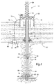
- Figure 1 is a schematic illustration of an offshore oil or gas drilling platform operating an embodiment of isolation subassemblies according to the present invention; and
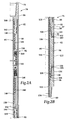
- Figures 2A-2B are quarter-sectional views of a downhole electromagnetic transmitter and receiver utilizing an embodiment of an isolation subassembly according to the present invention.
-
- While the making and using of various embodiments of the present invention are discussed in detail below, it should be appreciated that the present invention provides many applicable inventive concepts which can be embodied in a wide variety of specific contexts. The specific embodiments discussed herein are merely illustrative of specific ways to make and use the invention, and do not delimit the scope of the invention.
- Referring to Figure 1, a downhole electromagnetic signal transmitter and a downhole electromagnetic signal repeater in use in conjunction with an offshore oil and gas drilling operation are schematically illustrated and generally designated 10. A
semi-submersible platform 12 is centered over a submerged oil andgas formation 14 located belowsea floor 16. Asubsea conduit 18 extends fromdeck 20 ofplatform 12 towellhead installation 22 includingblowout preventers 24.Platform 12 has ahoisting apparatus 26 and aderrick 28 for raising and lowering drill string 30, includingdrill bit 32,electromagnetic transmitter 34 and downholeelectromagnetic signal repeater 36. - In a typical drilling operation,
drill bit 32 is rotated by drill string 30, such thatdrill bit 32 penetrates through the various earth strata, formingwellbore 38. Measurement of parameters such as bit weight, torque, wear and bearing conditions may be obtained bysensors 40 located in the vicinity ofdrill bit 32. Additionally, parameters such as pressure and temperature as well as a variety of other environmental and formation information may be obtained bysensors 40. The signal generated bysensors 40 may typically be analog, which must be converted to digital data before electromagnetic transmission in the present system. The signal generated bysensors 40 is passed into anelectronics package 42 including an analog to digital converter which converts the analog signal to a digital code utilizing "ones" and "zeros" for information transmission. -
Electronics package 42 may also include electronic devices such as an on/off control, a modulator, a microprocessor, memory and amplifiers.Electronics package 42 is powered by a battery pack which may include a plurality of batteries, such as nickel cadmium or lithium batteries, which are configured to provide proper operating voltage and current. - Once the
electronics package 42 establishes the frequency, power and phase output of the information,electronics package 42 feeds the information toelectromagnetic transmitter 34.Electromagnetic transmitter 34 may be a direct connect to drill string 30 or may electrically approximate a large transformer. The information is then carried uphole in the form ofelectromagnetic wave fronts 46 which propagate through the earth. Theseelectromagnetic wave fronts 46 are picked up byreceiver 48 ofelectromagnetic repeater 36 located uphole fromelectromagnetic transmitter 34. -
Electromagnetic repeater 36 is spaced along drill string 30 to receiveelectromagnetic wave fronts 46 whileelectromagnetic wave fronts 46 remain strong enough to be readily detected.Receiver 48 ofelectromagnetic repeater 36 may electrically approximate a large transformer. Aselectromagnetic wave fronts 46reach receiver 48, a current is induced inreceiver 48 that carries the information originally obtained bysensors 40. - The current from
receiver 48 is fed to anelectronics package 50 that may include a variety of electronic devices such as amplifiers, limiters, filters, a phase lock loop, shift registers and comparators.Electronics package 50 processes the signal and amplifies the signal to reconstruct the original waveform, compensating for losses and distortion occurring during the transmission ofelectromagnetic wave fronts 46 through the earth.Electronics package 50 forwards the signal to atransmitter 52 that generates and radiateselectromagnetic wave fronts 54 into the earth in the manner described with reference to transmitter 44 andelectromagnetic wave fronts 46. -
Electromagnetic wave fronts 54 are received byelectromagnetic pickup device 64 located onsea floor 16.Electromagnetic pickup device 64 may sense either the electric field or the magnetic field ofelectromagnetic wave front 54 usingelectric field sensors 66 or amagnetic field sensor 68 or both. -
Electromagnetic pickup device 64 then transmits the information received inelectromagnetic wave fronts 54 to the surface viawire 70 that is connected to buoy 72 andwire 74 that is connected to a processor onplatform 12. Upon reachingplatform 12, the information originally obtained bysensors 40 is further processed making any necessary calculations and error corrections such that the information may be displayed in a usable format. - Even though Figure 1 depicts a
single repeater 36, it should be noted by one skilled in the art that the number of repeaters, if any, located within drill string 30 will be determined by the depth ofwellbore 38, the noise level inwellbore 38 and the characteristics of the earth's strata adjacent to wellbore 38 in that electromagnetic waves suffer from attenuation with increasing distance from their source at a rate that is dependent upon the composition characteristics of the transmission medium and the frequency of transmission. For example, repeaters, such asrepeater 36, may be positioned between 2,000 and 5,000 ft apart (610 and 1524 m). Thus, ifwellbore 38 is 15,000 ft (4572 m) deep, between two and seven repeaters would be desirable. - Even though Figure 1 depicts
transmitter 34,repeater 36 andelectromagnetic pickup device 64 in an offshore environment, it should be understood by one skilled in the art thattransmitter 34,repeater 36 andelectromagnetic pickup device 64 are equally well-suited for operation in an onshore environment. In fact, in an onshore environment,electromagnetic pickup device 64 would be placed directly on the land. Alternatively, a receiver such asreceiver 48 could be used at the surface to pick up the electromagnetic wave fronts for processing at the surface. - Additionally, while Figure 1 has been described with reference to transmitting information uphole during a measurement while drilling operation, it should be understood by one skilled in the art that repeater 36 and
electromagnetic pickup device 64 may be used in conjunction with the transmission of information downhole from surface equipment to downhole tools to perform a variety of functions such as opening and closing a downhole tester valve or controlling a downhole choke. In this example,transmitter 34 would also serve as an electromagnetic receiver. - Further even though Figure 1 has been described with reference to one way communication from the vicinity of
drill bit 32 toplatform 12, it should be understood by one skilled in the art that the principles of the present invention are applicable to two way communications. For example, a surface installation may be used to request downhole pressure, temperature, or flow rate information fromformation 14 by sending electromagnetic wave fronts downhole usingelectromagnetic pickup device 64 as an electromagnetic transmitter and retransmitting therequest using repeater 36 as described above.Electromagnetic transmitter 34, serving as an electromagnetic receiver, would receive the electromagnetic wave fronts and pass the request to sensors, such assensors 40, located nearformation 14.Sensors 40 then obtain the appropriate information which would be returned to the surface viaelectromagnetic wave fronts 46 which would again be retransmitted byrepeater 36. As such, the phrase "between surface equipment and downhole equipment" as used herein encompasses the transmission of information from surface equipment downhole, from downhole equipment uphole or for two way communications. - Representatively illustrated in Figures 2A-2B is one embodiment of an electromagnetic transmitter and receiver, such as
electromagnetic transmitter 34, or a downhole electromagnetic signal repeater, such asrepeater 36, which is generally designated 76 and which will hereinafter be referred to asrepeater 76. For convenience of illustration, Figures 2A-2B depictrepeater 76 in a quarter sectional view.Repeater 76 has abox end 78 and apin end 80 such thatrepeater 76 is threadably adaptable to drill string 30.Repeater 76 has anouter housing 82 and amandrel 84 having a full bore so that whenrepeater 76 is interconnected with drill string 30, fluids may be circulated therethrough and therearound. Specifically, during a drilling operation, drilling mud is circulated through drill string 30 insidemandrel 84 ofrepeater 76 to ports formed throughdrill bit 32 and up the annulus formed between drill string 30 and wellbore 38 exteriorly ofhousing 82 ofrepeater 76.Housing 82 andmandrel 84 thereby protect the operable components ofrepeater 76 from drilling mud or other fluids disposed withinwellbore 38 and within drill string 30. -
Housing 82 ofrepeater 76 includes an axially extending generally tubularupper connecter 86 which hasbox end 78 formed therein.Upper connecter 86 may be threadably and sealably connected to drill string 30 for conveyance intowellbore 38. - An axially extending generally tubular
intermediate housing member 88 is threadably and sealably connected toupper connecter 86. An axially extending generally tubularlower housing member 90 is threadably and sealably connected tointermediate housing member 88. Collectively,upper connector 86,intermediate housing member 88 andlower housing member 90 formupper subassembly 92.Upper subassembly 92 is electrically connected to the section of drill string 30 aboverepeater 76. - An axially extending generally
tubular isolation subassembly 94 is securably and sealably coupled tolower housing member 90 byouter threads 96 andinner threads 97. An axially extending generally tubularlower connector 98 is securably and sealably coupled toisolation subassembly 94 byouter threads 100 andinner threads 101. -
Dielectric member 102 is disposed between theisolation subassembly 94 andlower housing number 90.Dielectric material 104 is disposed betweenouter threads 97 ofisolation subassembly 94 andinner threads 96 oflower housing member 90.Dielectric member 102 anddielectric material 104 are electrically insulating materials that provide substantial load bearing capabilities such as a ceramic, anodized aluminum or a resin such as mycarta. Similarly,dielectric member 106 is disposed betweenisolation subassembly 94 and thelower connector 98 whiledielectric material 108 is disposed betweenouter threads 100 ofisolation subassembly 94 andinner threads 101 oflower connector 98. -
Isolation subassembly 94 may be made of aluminum having a strength of, for example, a 60,000 psi (414 MPa).Isolation subassembly 94 may be anodized to confers an electrically insulating coating on the surface ofisolation subassembly 94. - An
outer sleeve 110 is disposed exteriorly ofisolation subassembly 94,lower housing member 90 andlower connector 98 betweenshoulder 112 oflower housing member 90 andshoulder 114 oflower connector 98.Outer sleeve 110 is formed from an electrically insulating material, such as pre-formed or built-up fiberglass.Outer sleeve 110 has the same outer diameter as thelower housing member 90 andlower connector 98.Outer sleeve 110 provides insulation toisolation subassembly 94 and protectsisolation subassembly 94 from corrosion and contact with the sides ofwellbore 38 and rig tongs whenisolation subassembly 94 is joined with other sections of drill string 30. - An
inner sleeve 116 is disposed on the inner surface ofisolation subassembly 94, and extends intolower housing member 90 andlower connector 98 betweenshoulder 118 oflower housing member 90 andshoulder 120 oflower connector 98.Inner sleeve 116 is an electrical insulator that helps protect the inner surface ofisolation subassembly 94 from, e.g., drilling mud and other corrosive materials. - The contact points between the
isolation subassembly 94 andlower housing member 90 andlower connector 98, respectively, are electrically insulated in several ways. Specifically, the outer surface ofisolation subassembly 94 may be anodized aluminum anddielectric members dielectric material isolation subassembly 94,lower housing member 90 andlower connector 98. In addition,inner threads 97 oflower housing member 90 andinner threads 101 oflower connector 98, which are made of steel, may be coated with an insulating material. For example, insulating materials such as ceramic, Teflon or an aluminum oxide coating are suitable. -
Outer sleeve 110 andinner sleeve 116 also provide electrical insulation betweenisolation subassembly 94,lower housing member 90 andlower connector 98. In addition to protectingisolation subassembly 94 from potential damage during handling and use such as scratching,outer sleeve 110 and inner sleeve 194, also provide for corrosion protection for the anodizedaluminum isolation subassembly 94. - Alternatively, with the use of
dielectric members dielectric material conductive isolation subassembly 94 constructed from, for example, steel, that is disposed betweenlower housing member 90 andlower connector 98. In this embodiment, a suitable insulating material such as ceramic, Teflon or an aluminum oxide coating may be placed betweeninner threads 97 oflower housing member 90 andouter threads 96 ofisolation subassembly 94 as well as betweeninner threads 101 oflower connector 98 andouter threads 100 ofisolation subassembly 94. Also, in this embodiment, the distance between thedielectric members isolation subassembly 94. - In the past, when an insulating coating was applied to threads, the contact stress of torquing the joint commonly damaged the coating.
Isolation subassembly 94 of the present invention provides a modified shoulder that allows the threads to be made up manually and then permits the threads to be loaded. Specifically,collar 109 may be used to loadouter threads 96 ofisolation subassembly 94 andinner threads 97 oflower housing member 90. First,isolation subassembly 94 andlower housing member 90 are mated together without applying full torque. Thereafter,collar 109 is rotated onouter thread 96 ofisolation subassembly 94 towardlower housing member 90, thereby loadingouter threads 96 andinner threads 97 without damaging the insulating coating. Likewise,collar 111 may be used to loadouter threads 100 ofisolation subassembly 94 andinner threads 101 oflower connector 98 in a similar manner. This procedure allows for the loading ofouter threads 100 andinner threads 101 without any sliding action to damage the coating.Collars - Alternatively,
isolation subassembly 94 may be coupled withlower housing member 90 andlower connector 98 using thermal torque.Outer threads isolation subassembly 94 are cooled, whileinner threads 97 oflower housing member 90 andinner threads 101 oflower connector 98 are heated. The respective threads are then joined together and torqued to a low value. Asouter threads isolation subassembly 94 heat up and whileinner threads 97 oflower housing member 90 andinner threads 101 oflower connector 98 cool, a load is created on the threads. By using the thermal torque assembly method, a large load may be placed onouter threads isolation subassembly 94 while eliminating the contact stress associated with high torque that can cause scratching of the anodized aluminumouter threads isolation subassembly 94 and the coated steelinner threads lower housing member 90 andlower connector 98, respectively. - Additionally, it should be noted by one skilled in the art that the threaded connections of
isolation subassembly 94 may be further strengthened by the addition of an epoxy therebetween, such as Halliburton Weld A. Likewise,dielectric members dielectric material outer sleeve 110 andinner sleeve 116 may be secured in place using an epoxy. - Thus,
isolation subassembly 94 provides a discontinuity in the electrical connection betweenlower connector 98 andupper subassembly 92 ofrepeater 76, thereby providing a discontinuity in the electrical connection between the portion of drill string 30 belowrepeater 76 and the portion of drill string 30 aboverepeater 76. - It should be apparent to those skilled in the art that the use of directional terms such as above, below, upper, lower, upward, downward, etc. are used in relation to the illustrative embodiments as they are depicted in the figures, the upward direction being toward the top of the corresponding figure and the downward direction being toward the bottom of the corresponding figure. It is to be understood that
repeater 76 may be operated in vertical, horizontal, inverted or inclined orientations without deviating from the principles of the present invention. -
Mandrel 84 includes axially extending generally tubularupper mandrel section 142 and axially extending generally tubularlower mandrel section 144.Upper mandrel section 142 is partially disposed and sealing configured withinupper connector 86. Adielectric member 146 electrically isolatesupper mandrel section 142 fromupper connector 86. The outer surface ofupper mandrel section 142 may have adielectric layer 148 disposed thereon.Dielectric layer 148 may be, for example, a Teflon layer. Together,dielectric layer 148 anddielectric member 146 serve to electrically isolateupper connector 86 fromupper mandrel section 142. - Between
upper mandrel section 142 andlower mandrel section 144 is adielectric member 150 that, along withdielectric layer 148, serves to electrically isolateupper mandrel section 142 fromlower mandrel section 144. Betweenlower mandrel section 144 andlower housing member 90 is adielectric member 152. On the outer surface oflower mandrel section 144 is adielectric layer 154 which, along withdielectric member 152, provides for electric isolation oflower mandrel section 144 fromlower housing number 90.Dielectric layer 154 also provides for electric isolation betweenlower mandrel section 144 andisolation subassembly 94 as well as betweenlower mandrel section 144 andlower connector 98.Lower end 156 oflower mandrel section 144 is disposed withinlower connector 98 and is in electrical communication withlower connector 98. -
Intermediate housing member 88 ofouter housing 82 andupper mandrel section 142 ofmandrel 84 defineannular area 158. Areceiver 160, anelectronics package 162 and atransmitter 164 are disposed withinannular area 158. In operation,receiver 160 receives an electromagnetic input signal carrying information which is transformed into an electrical signal that is passed ontoelectronics package 162 viaelectrical conductor 166.Electronics package 162 processes and amplifies the electrical signal. The electrical signal is then fed totransmitter 164 viaelectrical conductor 168.Transmitter 164 transforms the electrical signal into an electromagnetic output signal carrying information that is radiated into the earth utilizingisolation subassembly 94 to provide the electrical discontinuity necessary to generate the electromagnetic output signal. - It will be appreciated that the invention described above may be modified.
Claims (10)
- An electrically insulating gap subassembly for inclusion in a pipe string (30) comprising: a first tubular member (90) having a threaded end connector; a second tubular member (98) having a threaded end connector; and an isolation subassembly (94) having first and second threaded end connectors, the first threaded end connector of the isolation subassembly (94) being threadably coupled to the threaded end connector of the first tubular member (90) and the second threaded end connector of the isolation subassembly (94) being threadably coupled to the threaded end connector of the second tubular member (98), wherein the isolation subassembly (94) is made of aluminum.
- An electrically insulating gap subassembly according to claim 1, wherein the isolation subassembly (94) has an anodized surface.
- An electrically insulating gap subassembly according to claim 1 or 2, further comprising an outer sleeve (110) disposed exteriorly about the isolation subassembly (94).
- An electrically insulating gap subassembly according to claim 3, wherein the outer sleeve (110) extends exteriorly about a portion of the first and second tubular members (90,98).
- An electrically insulating gap subassembly according to claim 1, 2, 3 or 4, further comprising an inner sleeve (116) disposed interiorly within the isolation subassembly (94).
- An electrically insulating gap subassembly according to claim 4, wherein the inner sleeve (116) extends interiorly within a portion of the first and second tubular members (90,98).
- An electrically insulating gap subassembly for inclusion in a pipe string (32) comprising: a first tubular member having (90) a threaded end connector; a second tubular member (98) having a threaded end connector; an isolation subassembly (94) having first and second threaded end connectors, the first and second threaded end connector of the isolation subassembly (94) being threadably coupled to the threaded end connector of the first tubular member (90) and the threaded end connector of the second tubular member (98) respectively; first and second electrically insulating members (102,106) disposed respectively between the isolation subassembly (94) and the first and second tubular members (90,98); and an electrically insulating material (104,108) disposed respectively between the first and second threaded connectors of the isolation subassembly (94) and the threaded connectors of the first and second tubular members (90,98).
- An electrically insulating gap subassembly according to claim 8, wherein the first and second electrically insulating members (102,106) are anodized aluminum.
- A method for loading threads in an electrically insulating gap subassembly comprising the steps of: heating the threads of threaded end connectors of first and second tubular members (90,98); cooling the threads of first and second end connectors of an isolation subassembly (94); threadably coupling the threaded end connectors of the first and second tubular members (90,98) respectively to the first and second threaded end connectors of the isolation subassembly (94); substantially equalizing the temperature of threads of the threaded end connectors of the first and second tubular members (90,98) and the first and second threaded end connectors of the isolation subassembly (94), thereby loading the threads of the threaded end connectors of the first and second tubular members (90,98) and the first and second threaded end connectors of the isolation subassembly (94).
- A method according to claim 9, wherein the isolation subassembly (94) is anodized aluminum.
Applications Claiming Priority (2)
| Application Number | Priority Date | Filing Date | Title |
|---|---|---|---|
| US36886 | 1998-03-05 | ||
| US09/036,886 US6098727A (en) | 1998-03-05 | 1998-03-05 | Electrically insulating gap subassembly for downhole electromagnetic transmission |
Publications (2)
| Publication Number | Publication Date |
|---|---|
| EP0940557A2 true EP0940557A2 (en) | 1999-09-08 |
| EP0940557A3 EP0940557A3 (en) | 2000-11-22 |
Family
ID=21891213
Family Applications (1)
| Application Number | Title | Priority Date | Filing Date |
|---|---|---|---|
| EP99301634A Withdrawn EP0940557A3 (en) | 1998-03-05 | 1999-03-04 | Electrically insulating gap subassembly |
Country Status (4)
| Country | Link |
|---|---|
| US (2) | US6098727A (en) |
| EP (1) | EP0940557A3 (en) |
| CA (1) | CA2264090C (en) |
| NO (1) | NO991039L (en) |
Cited By (8)
| Publication number | Priority date | Publication date | Assignee | Title |
|---|---|---|---|---|
| WO2003004826A1 (en) * | 2001-06-30 | 2003-01-16 | Maxwell Downhole Technology Limited | Insulating device and assembly |
| WO2004076801A1 (en) * | 2003-02-28 | 2004-09-10 | Ryan Energy Technologies | Electrical isolation connector subassembly for use in directional drilling |
| GB2410512A (en) * | 2004-01-29 | 2005-08-03 | Schlumberger Holdings | Wellbore communication system |
| US7360796B2 (en) | 2003-02-28 | 2008-04-22 | Ryan Energy Technologies | Electrical isolation connector subassembly for use in directional drilling |
| WO2014149613A1 (en) * | 2013-03-15 | 2014-09-25 | Chevron U.S.A. Inc. | Method and system for monitoring subsurface injection processes using a borehole electromagnetic source |
| NO20151680A1 (en) * | 2013-07-15 | 2015-12-09 | Baker Hughes Inc | Electromagnetic Telemetry Apparatus and Methods for Use in Wellbores |
| EP2360497A3 (en) * | 2002-12-23 | 2015-12-16 | Halliburton Energy Services, Inc. | Drill String Telemetry System and Method |
| EP2972516A4 (en) * | 2013-03-14 | 2016-11-09 | Sharewell Energy Services Llc | Composite isolation joint for gap sub or internal gap |
Families Citing this family (55)
| Publication number | Priority date | Publication date | Assignee | Title |
|---|---|---|---|---|
| US7252160B2 (en) * | 1995-06-12 | 2007-08-07 | Weatherford/Lamb, Inc. | Electromagnetic gap sub assembly |
| CA2151525C (en) * | 1995-06-12 | 2002-12-31 | Marvin L. Holbert | Subsurface signal transmitting apparatus |
| US6572152B2 (en) * | 1999-12-29 | 2003-06-03 | Ryan Energy Technologies Inc. | Subassembly electrical isolation connector for drill rod |
| US6481495B1 (en) * | 2000-09-25 | 2002-11-19 | Robert W. Evans | Downhole tool with electrical conductor |
| AU2003274318A1 (en) * | 2002-10-10 | 2004-05-04 | Lucas, Brian, Ronald | Apparatus and method for transmitting a signal in a wellbore |
| GB0317547D0 (en) * | 2003-07-26 | 2003-08-27 | Weatherford Lamb | Sealing tubing |
| CA2476370C (en) * | 2003-07-31 | 2009-06-09 | Weatherford/Lamb, Inc. | Electromagnetic gap sub assembly |
| US7525315B2 (en) | 2004-04-01 | 2009-04-28 | Schlumberger Technology Corporation | Resistivity logging tool and method for building the resistivity logging tool |
| CA2509819C (en) * | 2004-06-14 | 2009-08-11 | Weatherford/Lamb, Inc. | Methods and apparatus for reducing electromagnetic signal noise |
| US20050284659A1 (en) * | 2004-06-28 | 2005-12-29 | Hall David R | Closed-loop drilling system using a high-speed communications network |
| US7493962B2 (en) * | 2004-12-14 | 2009-02-24 | Schlumberger Technology Corporation | Control line telemetry |
| US7477162B2 (en) | 2005-10-11 | 2009-01-13 | Schlumberger Technology Corporation | Wireless electromagnetic telemetry system and method for bottomhole assembly |
| CA2544457C (en) | 2006-04-21 | 2009-07-07 | Mostar Directional Technologies Inc. | System and method for downhole telemetry |
| US8593147B2 (en) | 2006-08-08 | 2013-11-26 | Halliburton Energy Services, Inc. | Resistivity logging with reduced dip artifacts |
| US20080078965A1 (en) * | 2006-09-28 | 2008-04-03 | Weatherford/Lamb, Inc. | Blowout preventer and pump rod clamp |
| CN101460698B (en) | 2006-12-15 | 2013-01-02 | 哈里伯顿能源服务公司 | Antenna coupling component measurement tool having rotating antenna configuration |
| EP2242899A4 (en) * | 2008-01-11 | 2015-06-24 | Schlumberger Technology Corp | Electromagnetic telemetry assembly with protected antenna |
| CA2680869C (en) | 2008-01-18 | 2011-07-12 | Halliburton Energy Services, Inc. | Em-guided drilling relative to an existing borehole |
| US9010461B2 (en) | 2009-06-01 | 2015-04-21 | Halliburton Energy Services, Inc. | Guide wire for ranging and subsurface broadcast telemetry |
| US8912915B2 (en) | 2009-07-02 | 2014-12-16 | Halliburton Energy Services, Inc. | Borehole array for ranging and crosswell telemetry |
| US9581718B2 (en) | 2010-03-31 | 2017-02-28 | Halliburton Energy Services, Inc. | Systems and methods for ranging while drilling |
| US8749243B2 (en) | 2010-06-22 | 2014-06-10 | Halliburton Energy Services, Inc. | Real time determination of casing location and distance with tilted antenna measurement |
| US8917094B2 (en) | 2010-06-22 | 2014-12-23 | Halliburton Energy Services, Inc. | Method and apparatus for detecting deep conductive pipe |
| US9115569B2 (en) | 2010-06-22 | 2015-08-25 | Halliburton Energy Services, Inc. | Real-time casing detection using tilted and crossed antenna measurement |
| US8844648B2 (en) | 2010-06-22 | 2014-09-30 | Halliburton Energy Services, Inc. | System and method for EM ranging in oil-based mud |
| WO2012002937A1 (en) | 2010-06-29 | 2012-01-05 | Halliburton Energy Services, Inc. | Method and apparatus for sensing elongated subterraean anomalies |
| US9360582B2 (en) | 2010-07-02 | 2016-06-07 | Halliburton Energy Services, Inc. | Correcting for magnetic interference in azimuthal tool measurements |
| US8523503B2 (en) | 2010-07-30 | 2013-09-03 | Nuovo Pignone, S.P.A. | Threaded joint and method of sealing a threaded joint |
| US8875791B2 (en) * | 2010-10-18 | 2014-11-04 | Schlumberger Technology Corporation | Segmented fiber optic coiled tubing assembly |
| US9772608B2 (en) * | 2010-12-20 | 2017-09-26 | Joe Spacek | Oil well improvement system—well monitor and control subsystem |
| AU2012383577B2 (en) | 2012-06-25 | 2015-07-09 | Halliburton Energy Services, Inc. | Tilted antenna logging systems and methods yielding robust measurement signals |
| US9829133B2 (en) | 2012-08-15 | 2017-11-28 | Ge Energy Oil Field Technology Inc. | Isolation ring on gap sub |
| WO2014075190A1 (en) | 2012-11-16 | 2014-05-22 | Evolution Engineering Inc. | Electromagnetic telemetry gap sub assembly with insulating collar |
| US9670739B2 (en) | 2012-11-29 | 2017-06-06 | Chevron U.S.A. Inc. | Transmitting power to gas lift valve assemblies in a wellbore |
| US9303507B2 (en) | 2013-01-31 | 2016-04-05 | Saudi Arabian Oil Company | Down hole wireless data and power transmission system |
| WO2014131133A1 (en) | 2013-03-01 | 2014-09-04 | Evolution Engineering Inc. | Pinned electromagnetic telemetry gap sub assembly |
| WO2014134741A1 (en) * | 2013-03-07 | 2014-09-12 | Evolution Engineering Inc. | Detection of downhole data telemetry signals |
| US9422802B2 (en) | 2013-03-14 | 2016-08-23 | Merlin Technology, Inc. | Advanced drill string inground isolator housing in an MWD system and associated method |
| WO2015031973A1 (en) * | 2013-09-05 | 2015-03-12 | Evolution Engineering Inc. | Transmitting data across electrically insulating gaps in a drill string |
| US10156102B2 (en) * | 2014-05-08 | 2018-12-18 | Evolution Engineering Inc. | Gap assembly for EM data telemetry |
| US10301887B2 (en) | 2014-05-08 | 2019-05-28 | Evolution Engineering Inc. | Drill string sections with interchangeable couplings |
| US10301891B2 (en) | 2014-05-08 | 2019-05-28 | Evolution Engineering Inc. | Jig for coupling or uncoupling drill string sections with detachable couplings and related methods |
| CN106460497B (en) * | 2014-05-09 | 2020-10-23 | 开拓工程股份有限公司 | Downhole electronic device carrier |
| US9267334B2 (en) * | 2014-05-22 | 2016-02-23 | Chevron U.S.A. Inc. | Isolator sub |
| DE102014220709A1 (en) * | 2014-10-13 | 2016-04-14 | Siemens Aktiengesellschaft | Mechanically supporting and electrically insulating mechanical connection |
| US10641081B2 (en) | 2015-02-24 | 2020-05-05 | Evolution Engineering Inc. | Device and method for retaining probe exterior wear sleeve |
| US10767469B2 (en) * | 2015-10-28 | 2020-09-08 | Halliburton Energy Services, Inc. | Transceiver with annular ring of high magnetic permeability material for enhanced short hop communications |
| RU2633884C2 (en) * | 2016-02-24 | 2017-10-19 | Общество с ограниченной ответственностью Научно-производственная фирма "ВНИИГИС-Забойные телеметрические комплексы" (ООО НПФ "ВНИИГИС-ЗТК") | Near-bit module (versions) |
| WO2018102932A1 (en) * | 2016-12-09 | 2018-06-14 | Evolution Engineering Inc. | Seal and sacrificial components for a drill string |
| WO2018125099A1 (en) | 2016-12-28 | 2018-07-05 | Halliburton Energy Services, Inc. | Deviated production well telemetry with assisting well/drillship |
| CA3047066C (en) | 2017-01-30 | 2022-11-29 | Halliburton Energy Services, Inc. | Gap sub impedance control |
| US10641050B1 (en) * | 2019-08-05 | 2020-05-05 | Isodrill, Inc. | Data transmission system |
| US10822884B1 (en) * | 2019-08-05 | 2020-11-03 | Isodrill, Inc. | Data transmission system |
| RU2732163C1 (en) * | 2019-12-19 | 2020-09-14 | Общество с ограниченной ответственностью "БИТАС" | Over-bit module |
| US11674380B2 (en) * | 2021-08-24 | 2023-06-13 | Saudi Arabian Oil Company | Smart retrievable service packers for pressure testing operations |
Citations (10)
| Publication number | Priority date | Publication date | Assignee | Title |
|---|---|---|---|---|
| US2364957A (en) * | 1939-08-08 | 1944-12-12 | Stanolind Oil & Gas Co | Electrical surveying |
| US3114566A (en) * | 1961-04-21 | 1963-12-17 | Kobe Inc | Shrink fit tubing joint |
| US3126214A (en) * | 1964-03-24 | Lip fou | ||
| US4012092A (en) * | 1976-03-29 | 1977-03-15 | Godbey Josiah J | Electrical two-way transmission system for tubular fluid conductors and method of construction |
| US4496174A (en) * | 1981-01-30 | 1985-01-29 | Tele-Drill, Inc. | Insulated drill collar gap sub assembly for a toroidal coupled telemetry system |
| US4691203A (en) * | 1983-07-01 | 1987-09-01 | Rubin Llewellyn A | Downhole telemetry apparatus and method |
| FR2618912A1 (en) * | 1987-07-30 | 1989-02-03 | Alsthom | Drilling system with electromagnetic transmission of information from the bottom, and insulating connector for this system |
| US5138313A (en) * | 1990-11-15 | 1992-08-11 | Halliburton Company | Electrically insulative gap sub assembly for tubular goods |
| US5396232A (en) * | 1992-10-16 | 1995-03-07 | Schlumberger Technology Corporation | Transmitter device with two insulating couplings for use in a borehole |
| US5441121A (en) * | 1993-12-22 | 1995-08-15 | Baker Hughes, Inc. | Earth boring drill bit with shell supporting an external drilling surface |
Family Cites Families (20)
| Publication number | Priority date | Publication date | Assignee | Title |
|---|---|---|---|---|
| US1494693A (en) * | 1921-08-22 | 1924-05-20 | Loi Peter | Collar protector for rotary drill pipes |
| US2400170A (en) * | 1942-08-29 | 1946-05-14 | Stanolind Oil & Gas Co | Time cycle telemetering |
| US2758818A (en) * | 1954-08-09 | 1956-08-14 | Rotary Oil Tool Co | Casing and drill pipe protectors |
| US2940787A (en) * | 1958-08-25 | 1960-06-14 | Ralph V Goodner | Electrically insulated sucker rod coupling |
| US4348672A (en) * | 1981-03-04 | 1982-09-07 | Tele-Drill, Inc. | Insulated drill collar gap sub assembly for a toroidal coupled telemetry system |
| US4387372A (en) * | 1981-03-19 | 1983-06-07 | Tele-Drill, Inc. | Point gap assembly for a toroidal coupled telemetry system |
| US4459597A (en) * | 1981-11-09 | 1984-07-10 | Orion Industries, Inc. | Isolated antenna assembly |
| US4579373A (en) * | 1982-07-06 | 1986-04-01 | Neal William J | Insulated concentric tubing joint assembly |
| US4674773A (en) * | 1984-01-23 | 1987-06-23 | Teleco Oilfield Services Inc. | Insulating coupling for drill collars and method of manufacture thereof |
| US4589187A (en) * | 1984-01-23 | 1986-05-20 | Teleco Oilfield Services Inc. | Method of manufacturing an insulating coupling for drill collars |
| US4616702A (en) * | 1984-05-01 | 1986-10-14 | Comdisco Resources, Inc. | Tool and combined tool support and casing section for use in transmitting data up a well |
| US4845493A (en) * | 1987-01-08 | 1989-07-04 | Hughes Tool Company | Well bore data transmission system with battery preserving switch |
| US4788544A (en) * | 1987-01-08 | 1988-11-29 | Hughes Tool Company - Usa | Well bore data transmission system |
| FR2635819B1 (en) * | 1988-09-01 | 1993-09-17 | Geoservices | ELECTRICALLY INSULATING CONNECTION SYSTEM FOR METALLIC TUBULAR ELEMENTS WHICH MAY PARTICULAR BE USED AS A LARGE DEPTH ANTENNA STRUCTURE |
| US5083821A (en) * | 1990-12-05 | 1992-01-28 | Itt Corporation | Extreme temperature thread sealing method and apparatus |
| US5160925C1 (en) * | 1991-04-17 | 2001-03-06 | Halliburton Co | Short hop communication link for downhole mwd system |
| US5130706A (en) * | 1991-04-22 | 1992-07-14 | Scientific Drilling International | Direct switching modulation for electromagnetic borehole telemetry |
| US5159978A (en) * | 1991-08-13 | 1992-11-03 | Halliburton Logging Services, Inc. | Connecting apparatus for logging tools including electrical feedthrough and isolation system with bridle assembly |
| US5467083A (en) * | 1993-08-26 | 1995-11-14 | Electric Power Research Institute | Wireless downhole electromagnetic data transmission system and method |
| US5749605A (en) * | 1996-03-18 | 1998-05-12 | Protechnics International, Inc. | Electrically insulative threaded connection |
-
1998
- 1998-03-05 US US09/036,886 patent/US6098727A/en not_active Expired - Lifetime
-
1999
- 1999-03-02 CA CA002264090A patent/CA2264090C/en not_active Expired - Lifetime
- 1999-03-03 NO NO991039A patent/NO991039L/en not_active Application Discontinuation
- 1999-03-04 EP EP99301634A patent/EP0940557A3/en not_active Withdrawn
-
2000
- 2000-03-30 US US09/539,457 patent/US6439324B1/en not_active Expired - Lifetime
Patent Citations (10)
| Publication number | Priority date | Publication date | Assignee | Title |
|---|---|---|---|---|
| US3126214A (en) * | 1964-03-24 | Lip fou | ||
| US2364957A (en) * | 1939-08-08 | 1944-12-12 | Stanolind Oil & Gas Co | Electrical surveying |
| US3114566A (en) * | 1961-04-21 | 1963-12-17 | Kobe Inc | Shrink fit tubing joint |
| US4012092A (en) * | 1976-03-29 | 1977-03-15 | Godbey Josiah J | Electrical two-way transmission system for tubular fluid conductors and method of construction |
| US4496174A (en) * | 1981-01-30 | 1985-01-29 | Tele-Drill, Inc. | Insulated drill collar gap sub assembly for a toroidal coupled telemetry system |
| US4691203A (en) * | 1983-07-01 | 1987-09-01 | Rubin Llewellyn A | Downhole telemetry apparatus and method |
| FR2618912A1 (en) * | 1987-07-30 | 1989-02-03 | Alsthom | Drilling system with electromagnetic transmission of information from the bottom, and insulating connector for this system |
| US5138313A (en) * | 1990-11-15 | 1992-08-11 | Halliburton Company | Electrically insulative gap sub assembly for tubular goods |
| US5396232A (en) * | 1992-10-16 | 1995-03-07 | Schlumberger Technology Corporation | Transmitter device with two insulating couplings for use in a borehole |
| US5441121A (en) * | 1993-12-22 | 1995-08-15 | Baker Hughes, Inc. | Earth boring drill bit with shell supporting an external drilling surface |
Cited By (17)
| Publication number | Priority date | Publication date | Assignee | Title |
|---|---|---|---|---|
| GB2394978A (en) * | 2001-06-30 | 2004-05-12 | Maxwell Downhole Technology Lt | Insulating device and assembly |
| GB2394978B (en) * | 2001-06-30 | 2005-04-20 | Maxwell Downhole Technology Lt | Insulating device and assembly |
| WO2003004826A1 (en) * | 2001-06-30 | 2003-01-16 | Maxwell Downhole Technology Limited | Insulating device and assembly |
| US7387167B2 (en) | 2001-06-30 | 2008-06-17 | Maxwell Downhole Technology, Ltd | Insulating device and assembly |
| EP2360497A3 (en) * | 2002-12-23 | 2015-12-16 | Halliburton Energy Services, Inc. | Drill String Telemetry System and Method |
| US7360796B2 (en) | 2003-02-28 | 2008-04-22 | Ryan Energy Technologies | Electrical isolation connector subassembly for use in directional drilling |
| WO2004076801A1 (en) * | 2003-02-28 | 2004-09-10 | Ryan Energy Technologies | Electrical isolation connector subassembly for use in directional drilling |
| US7364203B2 (en) | 2003-02-28 | 2008-04-29 | Ryan Energy Technologies | Reinforcement for arched type structure with beveled screwed ends |
| GB2410512A (en) * | 2004-01-29 | 2005-08-03 | Schlumberger Holdings | Wellbore communication system |
| GB2428440B (en) * | 2004-01-29 | 2008-04-09 | Schlumberger Holdings | Wellbore communication system |
| GB2410512B (en) * | 2004-01-29 | 2008-04-09 | Schlumberger Holdings | Wellbore communication system |
| US7880640B2 (en) | 2004-01-29 | 2011-02-01 | Schlumberger Technology Corporation | Wellbore communication system |
| GB2428440A (en) * | 2004-01-29 | 2007-01-31 | Schlumberger Holdings | Wellbore communication system |
| EP2972516A4 (en) * | 2013-03-14 | 2016-11-09 | Sharewell Energy Services Llc | Composite isolation joint for gap sub or internal gap |
| WO2014149613A1 (en) * | 2013-03-15 | 2014-09-25 | Chevron U.S.A. Inc. | Method and system for monitoring subsurface injection processes using a borehole electromagnetic source |
| NO20151680A1 (en) * | 2013-07-15 | 2015-12-09 | Baker Hughes Inc | Electromagnetic Telemetry Apparatus and Methods for Use in Wellbores |
| NO346475B1 (en) * | 2013-07-15 | 2022-08-29 | Baker Hughes Holdings Llc | Electromagnetic Telemetry Apparatus and Methods for Use in Wellbores |
Also Published As
| Publication number | Publication date |
|---|---|
| US6439324B1 (en) | 2002-08-27 |
| CA2264090C (en) | 2008-01-22 |
| EP0940557A3 (en) | 2000-11-22 |
| US6098727A (en) | 2000-08-08 |
| CA2264090A1 (en) | 1999-09-05 |
| NO991039D0 (en) | 1999-03-03 |
| NO991039L (en) | 1999-09-06 |
Similar Documents
| Publication | Publication Date | Title |
|---|---|---|
| US6098727A (en) | Electrically insulating gap subassembly for downhole electromagnetic transmission | |
| EP0911484B1 (en) | Electromagnetic signal repeater and method for use of same | |
| US6144316A (en) | Electromagnetic and acoustic repeater and method for use of same | |
| US6177882B1 (en) | Electromagnetic-to-acoustic and acoustic-to-electromagnetic repeaters and methods for use of same | |
| US6218959B1 (en) | Fail safe downhole signal repeater | |
| US5959548A (en) | Electromagnetic signal pickup device | |
| CA2078090C (en) | Method and apparatus for transmitting information between equipment at the bottom of a drilling or production operation and the surface | |
| US9109439B2 (en) | Wellbore telemetry system and method | |
| CA1174279A (en) | Point gap assembly for a toroidal coupled telemetry system | |
| CN1609410B (en) | Downhole telemetering system and method, and cable communication line | |
| EP0922836B1 (en) | Subsea repeater and method for use of the same | |
| US8665109B2 (en) | Wired drill pipe connection for single shouldered application and BHA elements | |
| US9634473B2 (en) | Redundant wired pipe-in-pipe telemetry system | |
| CA2259760A1 (en) | Electromagnetic resistivity tool and method for use of same | |
| CA2499331A1 (en) | Apparatus and method for transmitting a signal in a wellbore | |
| NO316573B1 (en) | Device and method of electromagnetic telemetry using a subsea well frame | |
| WO2017065961A1 (en) | Intelligent drilling riser | |
| US6208265B1 (en) | Electromagnetic signal pickup apparatus and method for use of same | |
| US11702932B2 (en) | Wired pipe with telemetry adapter | |
| CA2593416C (en) | Hybrid wellbore telemetry system and method | |
| WO2014046674A1 (en) | Pipe-in-pipe wired telemetry system | |
| US20230399897A1 (en) | Wired pipe with internal sensor module |
Legal Events
| Date | Code | Title | Description |
|---|---|---|---|
| PUAI | Public reference made under article 153(3) epc to a published international application that has entered the european phase |
Free format text: ORIGINAL CODE: 0009012 |
|
| AK | Designated contracting states |
Kind code of ref document: A2 Designated state(s): AT BE CH CY DE DK ES FI FR GB GR IE IT LI LU MC NL PT SE |
|
| AX | Request for extension of the european patent |
Free format text: AL;LT;LV;MK;RO;SI |
|
| PUAL | Search report despatched |
Free format text: ORIGINAL CODE: 0009013 |
|
| AK | Designated contracting states |
Kind code of ref document: A3 Designated state(s): AT BE CH CY DE DK ES FI FR GB GR IE IT LI LU MC NL PT SE |
|
| AX | Request for extension of the european patent |
Free format text: AL;LT;LV;MK;RO;SI |
|
| AKX | Designation fees paid | ||
| REG | Reference to a national code |
Ref country code: DE Ref legal event code: 8566 |
|
| STAA | Information on the status of an ep patent application or granted ep patent |
Free format text: STATUS: THE APPLICATION IS DEEMED TO BE WITHDRAWN |
|
| 18D | Application deemed to be withdrawn |
Effective date: 20010523 |