EP0941806A2 - Wafer polishing device with moveable window - Google Patents
Wafer polishing device with moveable window Download PDFInfo
- Publication number
- EP0941806A2 EP0941806A2 EP99301765A EP99301765A EP0941806A2 EP 0941806 A2 EP0941806 A2 EP 0941806A2 EP 99301765 A EP99301765 A EP 99301765A EP 99301765 A EP99301765 A EP 99301765A EP 0941806 A2 EP0941806 A2 EP 0941806A2
- Authority
- EP
- European Patent Office
- Prior art keywords
- window
- polishing
- wafer
- belt
- platen
- Prior art date
- Legal status (The legal status is an assumption and is not a legal conclusion. Google has not performed a legal analysis and makes no representation as to the accuracy of the status listed.)
- Granted
Links
- 238000005498 polishing Methods 0.000 title claims abstract description 250
- 238000011065 in-situ storage Methods 0.000 claims abstract description 14
- 238000012544 monitoring process Methods 0.000 claims abstract description 12
- 238000012625 in-situ measurement Methods 0.000 claims abstract description 6
- 238000006073 displacement reaction Methods 0.000 claims description 29
- 230000007246 mechanism Effects 0.000 claims description 28
- 239000012530 fluid Substances 0.000 claims description 15
- 239000000463 material Substances 0.000 claims description 15
- 238000000034 method Methods 0.000 claims description 13
- 239000000126 substance Substances 0.000 claims description 8
- 230000008878 coupling Effects 0.000 claims 2
- 238000010168 coupling process Methods 0.000 claims 2
- 238000005859 coupling reaction Methods 0.000 claims 2
- 238000005259 measurement Methods 0.000 abstract description 39
- 238000007517 polishing process Methods 0.000 abstract description 8
- 238000012545 processing Methods 0.000 abstract description 5
- 230000002939 deleterious effect Effects 0.000 abstract description 3
- 239000003795 chemical substances by application Substances 0.000 description 23
- 230000003287 optical effect Effects 0.000 description 12
- 239000010935 stainless steel Substances 0.000 description 11
- 229910001220 stainless steel Inorganic materials 0.000 description 11
- JOYRKODLDBILNP-UHFFFAOYSA-N Ethyl urethane Chemical compound CCOC(N)=O JOYRKODLDBILNP-UHFFFAOYSA-N 0.000 description 8
- 239000004020 conductor Substances 0.000 description 8
- 230000008569 process Effects 0.000 description 8
- 239000002245 particle Substances 0.000 description 7
- 239000004744 fabric Substances 0.000 description 5
- 239000002759 woven fabric Substances 0.000 description 5
- 238000010276 construction Methods 0.000 description 4
- 229920000271 Kevlar® Polymers 0.000 description 3
- 230000005540 biological transmission Effects 0.000 description 3
- 239000004761 kevlar Substances 0.000 description 3
- 239000004065 semiconductor Substances 0.000 description 3
- 229920000742 Cotton Polymers 0.000 description 2
- 239000000945 filler Substances 0.000 description 2
- 230000033001 locomotion Effects 0.000 description 2
- 230000009467 reduction Effects 0.000 description 2
- 229920002803 thermoplastic polyurethane Polymers 0.000 description 2
- 239000004593 Epoxy Substances 0.000 description 1
- 230000005355 Hall effect Effects 0.000 description 1
- 244000043261 Hevea brasiliensis Species 0.000 description 1
- 239000003082 abrasive agent Substances 0.000 description 1
- 239000000853 adhesive Substances 0.000 description 1
- 230000001070 adhesive effect Effects 0.000 description 1
- 230000002411 adverse Effects 0.000 description 1
- 125000001931 aliphatic group Chemical group 0.000 description 1
- 239000004760 aramid Substances 0.000 description 1
- 238000000149 argon plasma sintering Methods 0.000 description 1
- 229920003235 aromatic polyamide Polymers 0.000 description 1
- 125000003118 aryl group Chemical group 0.000 description 1
- 238000005266 casting Methods 0.000 description 1
- 238000006243 chemical reaction Methods 0.000 description 1
- 239000008367 deionised water Substances 0.000 description 1
- 229920001971 elastomer Polymers 0.000 description 1
- 238000005516 engineering process Methods 0.000 description 1
- 230000003628 erosive effect Effects 0.000 description 1
- 239000000835 fiber Substances 0.000 description 1
- 239000003292 glue Substances 0.000 description 1
- 230000002209 hydrophobic effect Effects 0.000 description 1
- 229920000126 latex Polymers 0.000 description 1
- 239000004816 latex Substances 0.000 description 1
- 239000002184 metal Substances 0.000 description 1
- 229910001092 metal group alloy Inorganic materials 0.000 description 1
- 239000003595 mist Substances 0.000 description 1
- 238000012986 modification Methods 0.000 description 1
- 230000004048 modification Effects 0.000 description 1
- 238000000465 moulding Methods 0.000 description 1
- 229920003052 natural elastomer Polymers 0.000 description 1
- 229920001194 natural rubber Polymers 0.000 description 1
- 229920000642 polymer Polymers 0.000 description 1
- 229920001296 polysiloxane Polymers 0.000 description 1
- 230000011514 reflex Effects 0.000 description 1
- 239000011347 resin Substances 0.000 description 1
- 229920005989 resin Polymers 0.000 description 1
- 230000004044 response Effects 0.000 description 1
- 238000006748 scratching Methods 0.000 description 1
- 230000002393 scratching effect Effects 0.000 description 1
- 125000006850 spacer group Chemical group 0.000 description 1
- 150000003673 urethanes Chemical class 0.000 description 1
- XLYOFNOQVPJJNP-UHFFFAOYSA-N water Substances O XLYOFNOQVPJJNP-UHFFFAOYSA-N 0.000 description 1
Images


Classifications
-
- B—PERFORMING OPERATIONS; TRANSPORTING
- B24—GRINDING; POLISHING
- B24D—TOOLS FOR GRINDING, BUFFING OR SHARPENING
- B24D7/00—Bonded abrasive wheels, or wheels with inserted abrasive blocks, designed for acting otherwise than only by their periphery, e.g. by the front face; Bushings or mountings therefor
- B24D7/12—Bonded abrasive wheels, or wheels with inserted abrasive blocks, designed for acting otherwise than only by their periphery, e.g. by the front face; Bushings or mountings therefor with apertures for inspecting the surface to be abraded
-
- H—ELECTRICITY
- H01—ELECTRIC ELEMENTS
- H01L—SEMICONDUCTOR DEVICES NOT COVERED BY CLASS H10
- H01L21/00—Processes or apparatus adapted for the manufacture or treatment of semiconductor or solid state devices or of parts thereof
- H01L21/02—Manufacture or treatment of semiconductor devices or of parts thereof
- H01L21/04—Manufacture or treatment of semiconductor devices or of parts thereof the devices having at least one potential-jump barrier or surface barrier, e.g. PN junction, depletion layer or carrier concentration layer
- H01L21/18—Manufacture or treatment of semiconductor devices or of parts thereof the devices having at least one potential-jump barrier or surface barrier, e.g. PN junction, depletion layer or carrier concentration layer the devices having semiconductor bodies comprising elements of Group IV of the Periodic System or AIIIBV compounds with or without impurities, e.g. doping materials
- H01L21/30—Treatment of semiconductor bodies using processes or apparatus not provided for in groups H01L21/20 - H01L21/26
- H01L21/302—Treatment of semiconductor bodies using processes or apparatus not provided for in groups H01L21/20 - H01L21/26 to change their surface-physical characteristics or shape, e.g. etching, polishing, cutting
-
- B—PERFORMING OPERATIONS; TRANSPORTING
- B24—GRINDING; POLISHING
- B24B—MACHINES, DEVICES, OR PROCESSES FOR GRINDING OR POLISHING; DRESSING OR CONDITIONING OF ABRADING SURFACES; FEEDING OF GRINDING, POLISHING, OR LAPPING AGENTS
- B24B21/00—Machines or devices using grinding or polishing belts; Accessories therefor
- B24B21/04—Machines or devices using grinding or polishing belts; Accessories therefor for grinding plane surfaces
-
- B—PERFORMING OPERATIONS; TRANSPORTING
- B24—GRINDING; POLISHING
- B24B—MACHINES, DEVICES, OR PROCESSES FOR GRINDING OR POLISHING; DRESSING OR CONDITIONING OF ABRADING SURFACES; FEEDING OF GRINDING, POLISHING, OR LAPPING AGENTS
- B24B37/00—Lapping machines or devices; Accessories
- B24B37/04—Lapping machines or devices; Accessories designed for working plane surfaces
-
- B—PERFORMING OPERATIONS; TRANSPORTING
- B24—GRINDING; POLISHING
- B24B—MACHINES, DEVICES, OR PROCESSES FOR GRINDING OR POLISHING; DRESSING OR CONDITIONING OF ABRADING SURFACES; FEEDING OF GRINDING, POLISHING, OR LAPPING AGENTS
- B24B49/00—Measuring or gauging equipment for controlling the feed movement of the grinding tool or work; Arrangements of indicating or measuring equipment, e.g. for indicating the start of the grinding operation
- B24B49/12—Measuring or gauging equipment for controlling the feed movement of the grinding tool or work; Arrangements of indicating or measuring equipment, e.g. for indicating the start of the grinding operation involving optical means
Definitions
- Chemical-mechanical polishing is a well-known technique for removing materials on a semiconductor wafer using a polishing device and a polishing agent
- the mechanical movement of the polishing device relative to the wafe in combination with the chemical reaction of the polishing agent provide an abrasive force with chemical erosion to planarize the exposed surface of the wafer or a layer formed on the wafer.
- Rotating, orbital, and linear polishers are three types of tools that can be used in the CMP process.
- a rotating polisher a rotating wafer holder supports a wafer, and a polishing pad on a moving platen rotates relative to the wafer surface.
- the platen of an orbital polisher orbits as opposed to rotates during polishing.
- a linear polisher a flexible belt moves a polishing pad linearly across a wafer surface, providing a more uniform velocity profile across the surface of the wafer as compared to rotating or orbital polishers.
- CMP polishers can incorporate various in-situ monitoring techniques to monitor the polished surface of the wafer to determine the end point of the polishing process.
- U.S. Patent No. 5,433,651 and European Patent Application No. EP 0 738 561 A1 describe rotating polishers that are designed for in-situ monitoring.
- a rotating polishing platen has a fixed window, which is flush with the platen but not with the polishing pad on the platen. As the platen rotates, the window passes over an in-situ monitor, which takes a reflectance measurement indicative of the end point of the polishing process. Because the top surface of the window is below the top surface of the polishing pad, polishing agent collects in the recess above the window, adversely affecting the measurement by scattering light traveling through the window.
- European Patent Application No. EP 0 738 561 A1 discloses a rotating polishing platen with a fixed window, which, unlike the one in the '651 patent, is substantially flush with or formed from the polishing pad. Because the top surface of the window is in the same plane as the top surface of the polishing pad during the entire polishing process, the optical transparency of the window can be damaged when the wafer slides over the window and when pad conditioners cut small groves across the polishing pad. Since the window is not replaceable, once the window is damaged, the entire pad-window polishing device must be replaced even if the polishing pad itself does not need to be replaced.
- the preferred embodiments described below include a polishing device that can be used for in-situ monitoring of a wafer during CMP processing.
- the polishing devices of these preferred embodiments contain a movable window.
- the window remains in a position away from the polishing surface of the polishing device to protect the window from the deleterious effects of the polishing process.
- the polishing device positions the window between the wafer and a measurement sensor, the window moves to a position closer to the polishing surface of the polishing device. In this position, at least some polishing agent collected in the recess between the window and polishing surface is removed, and an in-situ measurement can be taken with reduced interference.
- the window After the polishing device positions the window away from the wafer and measurement sensor, the window returns to a position farther away from the polishing surface of the polishing device.
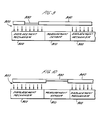
- Figure 1 is an illustration of a polishing device of a preferred embodiment with a movable window in a first position.
- Figure 2 is an illustration of a polishing device of a preferred embodiment with a movable window in a position closer to a polishing surface of the polishing device.
- Figure 3 is an illustration of a polishing device of a preferred embodiment comprising a single-piece flexible window.
- Figure 4 is an illustration of a polishing device ofa preferred embodiment comprising a flat-sheet flexible window.
- Figure 5 is an illustration of a polishing device of a preferred embodiment comprising a sliding window.
- Figure 6 is an illustration of a polishing device of a preferred embodiment comprisin a bellows window.
- Figure 7 is an illustration of a polishing device of a preferred embodiment in which a window displacement mechanism is disposed over a measurement sensor.
- Figure 8 is an illustration of a polishing device ofa preferred embodiment in which a magnet and a set of conductors are operative to move a window from a first to a second position.
- Figure 9 is an illustration of a polishing device of a preferred embodiment in which a movable window is drawn towards a window displacement mechanism.
- Figure 10 is an illustration of a polishing device of a preferred embodiment in which a movable window is moved closer to a polishing surface when the window is positioned away from a window displacement mechanism.
- Figure 11 is an illustration of a linear polishing tool of a preferred embodiment.
- Figure 12 is an illustration of a rotating polishing tool of a preferred embodiment.
- FIGS. 1 and 2 illustrate a polishing device 100 of a preferred embodiment that can be used for in-situ monitoring of a wafer during CMP processing.
- a polishing device 100 comprises an opening, which is filled by a window 110 affixed to the polishing device 100 by a flexible diaphragm 120.
- a wafer 140 undergoing CMP Located above the polishing device 100 is a wafer 140 undergoing CMP, and located below the polishing device 100 is a measurement sensor 130 for performing in-situ monitoring of the wafer 140 during CMP.
- the term "polishing device” in this specification and the following claims is intended broadly to encompass any device capable of performing CMP processing on a semiconductor wafer.
- a “polishing device” comprises a polishing surface, which is typically a polishing pad integrated with or affixed to the top of a polishing device subassembly.
- Polishing devices include, but are not limited to, a polishing pad and belt used in a linear polisher, a polishing pad and movable platen used in a rotating polisher, and a polishing pad and movable platen used in an orbital polisher.
- the polishing device 100 of figures 1 and 2 comprises a window, 110 that is movable from a first position to a second position.
- the window 110 is positioned away from the wafer 140 and the polishing surface of the polishing device 100 ( Figure 1).
- the window 110 is moved to a position closer to the polishing surface of the polishing device 100 ( Figure 2). It is preferred that the top surface of the window 110 be substantially flush with the top surface of the polishing device 100 when the window 110 is in the second position.
- the measurement sensor 130 takes a measurement of the surface of the wafer 140 through the window 110. After the polishing device 100 moves the window 110 away from the measurement location the window 110 is returned to a position farther away from the polishing surface of the polishing device 100.
- the polishing device 100 has a movable window 110, the problems associated with the prior art are overcome. Specifically, because the window 110 is below the polishing surface of the polishing device 100 for some or most of the CMP process, the window 110 is not damaged by the deleterious effects of the polishing process. By being below the polishing surface of the polishing device 100, the optical transparency of the window 110 is not damaged by conditioners that cut small grooves across the polishing surface during CMP to enhance the polishing operation. Further, because the window 110 moves closer to the polishing surface when a wafer measurement it taken, at least some polishing agent collected in the recess between the window 110 and polishing surface is removed, and an in-situ measurement can be taken with reduced interference. Additionally, in contrast to the fixed windows of prior art polishing devices, the window 110 of this preferred embodiment is easily replaceable. Since the window is easily replaceable, it alone, instead of the entire polishing device, can be replaced when the optical transparency of the window deteriorates.
- the window 110 is movably mounted to the polishing device by a flexible diaphragm 120.
- the window 110 is made from urethane It is important to note that a single urethane (preferably aromatic or aliphatic) or a combination of urethanes can be used. It is preferred that the window 110 have an area of about 1 to 100 cm 2 , a thickness of about 0.002 to 0.050 inches (most preferably about 0.010 to 0.015 inches), a hardness of about 25 Shore A to 75 Shore D (most preferably about 45 Shore D), and high optical transmission for ultraviolet and infrared light (about 200 to 1200 nm, most preferably about 300 to 800 nm). It is preferred that the first surface of the window be coated with a slurry-phobic material, such as a silicone, lyophilic or hydrophobic material.
- a slurry-phobic material such as a silicone, lyophilic or hydrophobic material.
- the flexible diaphragm 120 is made preferably from a latex or natural rubber, although any other material that provides enough lift to remove polishing agent from the recess above the window 110 can be used. It is preferred that the flexible diaphragm 120 have an area of about 1 to 100 cm 2 (most preferably about 25 cm 2 ) and a thickness of about 0.001 to 0.040 inches (most preferably about 0.008 inches). Preferably, a hole is made in the flexible diaphragm 120 about the size of the window 110, and the edges of the window 110 are affixed to the flexible diaphragm 120 using about a 0.001 to 0.020 inch-thick layer (most preferably a 0.005 inch-thick layer) of urethane epoxy.
- the flexible diaphragm/window component then can be affixed to the polishing device using any suitable glue.
- the flexible diaphragm 120 is glued into a recess in the polishing device 100.
- a single-piece window 300 ( Figure 3) with the appropriate optical and flexibility characteristics can be used. It is preferred that the single-piece window 300 be made of urethane and have high optical transmission for ultraviolet and infrared light (about 200 to 1200 nm, most preferably about 300 to 800 nm). It is further preferred that the center ofthe single-piece window 300 have a thickness of about 0.002 to 0.050 inches (most preferably about 0.010 to 0.015 inches) and that the edge flange of the single-piece window 300 have a thickness of about 0.001 to 0.040 inches (most preferably about 0.006 inches).
- the single-piece window 300 In operation, when positioned under the wafer, the single-piece window 300 flexes toward the polishing surface of the polishing device, and a measurement sensor takes a measurement of the surface of the wafer through the single-piece window 300. After the polishing device moves the single-piece window 300 away from the measurement location, the single-piece window 300 returns to a position farther away from the polishing surface of the polishing device.
- a flat-sheet window 400 is used. It is preferred that the flat-sheet window 400 be made of urethane, have high optical transmission for ultraviolet and infrared light (about 200 to 1200 nm, most preferably about 300 to 800 nm), and have a thickness of about 0.002 to 0.050 inches (most preferably about 0.010 inches).
- the flat-sheet window 400 flexes toward the polishing surface of the polishing device, and a measurement sensor takes a measurement of the surface of the wafer through the flat-sheet window 400. After the polishing device moves the flat-sheet window 400 away from the measurement location, the flat-sheet window 400 returns to a position farther away from the polishing surface of the polishing device.
- Figure 5 illustrates another alternative in which a sliding window 500 is used.
- the sliding window 500 slides closer to the polishing surface of the polishing device. After the polishing device moves the sliding window 500 away from the measurement location, the sliding window 500 slides back to a position farther away from the polishing surface of the polishing device.
- the polishing device is shaped to retain the sliding window 500 as it slides closer to and farther away from the polishing surface of the polishing device.
- Figure 6 illustrates another preferred embodiment in which a bellows window 600 is employed.
- the bellows window 600 moves into a measurement location under the wafer, the bellows window 600 extends closer to the polishing surface of the polishing device.
- the bellows window 600 moves away from the measurement location, it returns to a position farther away from the polishing surface of the polishing device.
- any window construction that allows the window to move closer to the polishing surface is encompassed by this invention. Further, any window size or shape can be used. It is preferred, however, that, When the window is not moved closer to the polishing surface, the window be positioned below the grooves created by a polishing-device conditioner. (In a polishing pad with a thickness of 50 mils, the grooves are typically 20 mils thick.)
- the window can be moved from the first to the second position with any suitable means.
- a window displacement mechanism 710 is positioned beneath the polishing device 740 near the measurement sensor 720.
- the window displacement mechanism 710 is positioned above the measurement sensor 720 and contains an opening through which the measurement sensor 720 can monitor the wafer 730.
- the measurement sensor 720 can be positioned above or adjacent to the window displacement mechanism 710.
- the polishing device 740 positions the window 750 over the window displacement mechanism 710, the window displacement mechanism 710 moves the window 750 closer to the polishing surface of the polishing device 740.
- the resilient nature of the diaphragm or window causes the window 750 to return to a position farther away from the wafer 730 and the polishing surface ofthe polishing device 740.
- a second window displacement mechanism can be used to lower the window 750 away from the polishing surface.
- the window displacement mechanism can take any number of different forms.
- the window displacement mechanism can employ air pressure, water pressure, pressure from mechanical attachments, electromagnetic pressure, or any combination thereof. It is preferred, however, that the window displacement mechanism be a fluid platen. Fluid platens are described in a patent application titled "Control Of Chemical-Mechanical Polishing Rate Across A Wafer Surface For A Linear Polisher;" Serial No. 08/638,462; filed April 26, 1996 and in U.S. Patent Nos. 5,558,568 and 5,593,344, all of which are hereby incorporated by reference.
- the window displacement mechanism is disposed at least partially in the polishing device.
- a window 810 and a flexible member 830 comprising a set of current-carrying conductors 840 are disposed in a polishing device 820.
- a magnet 850 disposed in the polishing device 820 creates a magnetic field across the set of current carrying conductors 840. When current is caused to flow through the conductors 840, electromagnetic forces on the conductors 840 move the flexible member 830 and the window 810 closer or farther away from the polishing surface of the polishing device 820, depending on the direction of the current flow.
- a position sensor such as, but not limited to, a Hall-effect sensor, eddy-current sensor, optical interrupter, acoustic sensor, or optical sensor.
- the rest position of the window is away from the polishing surface.
- the rest position of the window is can be in a position closer to the polishing surface, and a window displacement mechanism can be used to move the window away from the polishing surface at the appropriate time (e.g. , when the window is located at a pad-conditioning station).
- a window displacement mechanism 900 is disposed on either side of a measurement sensor 910.
- the window displacement mechanism 900 can comprise any suitable mechanism (such as a vacuum or a magnet, for example) to generate a displacement force 920.
- the displacement force 920 draws the window 930 away from the polishing surface when the polishing device 940 positions the window 930 over the window displacement mechanism 900.
- the window 930 When the polishing device 940 positions the window 930 between the wafer (not shown) and the measurement sensor 910 (a location in which there is no window displacement mechanism 900), the window 930 is allowed to move to its rest position closer to the polishing surface, as shown in Figure 10. After the polishing device 940 positions the window 930 away from the measurement sensor 910 and again over the window displacement mechanism 900, the window 930 is again drawn farther away from the polishing surface ( Figure 9). Such a mechanism would be particularly useful to move the window safely below the pad cutting surface of the pad conditioner.
- a first displacement force is used to position the window closer to (or farther away from) the polishing surface.
- the window remains in this position (even it the window is moved into or out of the measurement location) until a second displacement force moves the window farther way from (or closer to) the polishing surface. In this way, the window would act as a flip-flop.
- FIG. 11 is an illustration of a preferred embodiment in which the polishing device includes a belt 1120 on a linear polisher 1100, and the window displacement mechanism includes a fluid platen 1155.
- the linear polisher 1100 has a wafer carrier 1110 attached to a polishing head 1105 that secures the wafer with a mechanical retaining means, such as a retainer ring and/or a vacuum.
- a carrier film such as that available from Rodel (DF200) be used between the wafer and the wafer carrier 1110.
- the wafer carrier 1110 rotates the wafer over the belt 1120, which moves about first and second rollers 1130 and 1135.
- the rollers 1130, 1135 are preferably between about 2 to 40 inches in diameter.
- Driving means such as a motor (not shown), rotates the rollers 1130, 1135, causing the belt 1120 to move in a linear motion with respect to the surface of the wafer.
- the belt 1120 moves at a rate of about 200 to 1000 ft/minute (most preferably about 400 ft/minute).
- belt refers to a closed-loop element comprising at least one layer including a layer of polishing material. A discussion of the layer(s) of the belt element is developed below. It is preferred that the belt 1120 have a width of 13 inches and be tensioned with a force of about 600 Ibs.
- a polishing agent dispensing mechanism 1140 provides polishing agent to the belt 1120, preferably at a flow rate of about 100 to 300 ml/minute.
- the polishing agent preferably has a pH of about 1.5 to about 12.
- One type of polishing agent that can be used is Klebesol available from Hoechst, although other types of polishing agent can be used depending on the application.
- Klebesol available from Hoechst, although other types of polishing agent can be used depending on the application.
- the polishing agent moves under the wafer along with the belt 1120 and may be in partial or complete contact with the wafer at any instant in time during the polishing process.
- a conditioner (such as those available from Niabraze Corporation and TBW Industries, Inc.) can be used to recondition the belt 1120 during use by scratching the belt 1120 to remove polishing agent residue build-up and/or pad deformation.
- the belt 1120 moves between the fluid platen 1155 and the wafer. It is preferred that the fluid platen 1155 have an air bearing and have about 1-30 fluid flow channels. It also is preferred that a pre-wet layer of de-ionized water mist be used between the platen 1155 and the belt 1120 to prevent blockage of the flow channels by any polishing agent that comes underneath the belt 1120.
- the fluid platen 1155 provides a supporting platform on the underside of the belt 1120 to ensure that the belt 1120 makes sufficient contact with the wafer for uniform polishing.
- the wafer carrier 1110 presses downward against the belt 1120 with appropriate force (preferably about 5 psi) so that the belt 1120 makes sufficient contact with the wafer for performing CMP.
- the fluid platen 1155 provides a necessary counteracting support to this downward force.
- the fluid platen 1155 can be used to control forces exerted against the underside of the belt 1120. By such fluid flow control, pressure variations exerted by the belt 1120 on the wafer can be controlled to provide a more uniform polishing rate of the wafer.
- the belt 1120 contains a movable window 1190 as described above.
- the movable window 1190 passes under the wafer carrier 1105 and over the fluid platen 1155 and a measurement sensor 1195.
- fluid from the platen 1155 lifts the window 1190 closer to the polishing surface of the belt 1120, preferably so that the window 1190 is substantially flush with the polishing surface.
- an optical circuit is completed, and in-situ monitoring can be performed.
- a short-distance diffuse reflex sensor such as a Sunx model number CX-24 sensor
- a “belt” comprises at least one layer of material, including a layer of polishing material.
- a belt comprises at least one layer of material, including a layer of polishing material.
- a stainless steel belt which can be purchased from Belt Technologies, having a width of about 14 inches and a length of about 93.7 inches, inner diameter.
- a base layer selected from the group consisting of aramid, cotton, metal, metal alloys, or polymers can be used. The preferred construction of this multi-layered belt is as follows.
- the stainless steel belt is placed on the set of rollers ofthe CMP machine and is put under about 2,000 lbs of tension.
- a layer of polishing material preferably Rodel's IC 1000 polishing pad
- the subassembly is them removed from the rollers and an underpad, preferably made of PVC, is attached to the underside of the stainless steel belt with an adhesive capable of withstanding the conditions of the CMP process.
- the constructed belt preferably will have a total thickness of about 90 mils: about 50 mils of which is the layer of polishing material, about 20 mils of which is the stainless steel belt, and about 20 mils of which is the PVC underpad.
- the belt can be formed as one integrated component as described in a patent application titled “Integrated Pad and Belt for Chemical Mechanical Polishing," Serial No. 08/800,373, filed February 14, 1997, hereby incorporated by reference.
- This belt is formed around a woven Kevlar fabric. It has been found that a 16/3 Kevlar, 1500 Denier fill and a 16/2 cotton, 650 Denier warp provide the best weave characteristics.
- "fill” is yarn in the tension-bearing direction
- warp is yarn in the direction perpendicular to the tension bearing direction.
- “Denier” defines the density and diameter of the mono-filament. The first number represents the number of twists per inch, and the second number refers to the number of filaments that are twisted in an inch.
- the woven fabric is placed in a mold that preferably has the same dimensions as the stainless steel belt described above.
- a clear urethane resin is poured into the mold under a vacuum, and the assembly is then baked, de-molded, cured, and ground to the desired dimension.
- the resin may be mixed with fillers or abrasives in order to achieve desired material properties and/or polishing characteristics. Since fillers and abrasive particles in the polishing layer may scratch the polished article, it is desired that their average particle size be less than about 100 microns.
- a layer of polishing material preferably a Rodel IC 1000 polishing pad, can be attached to the woven fabric or the preconstructed belt as it was on the stainless steel belt.
- fi!!ers and/or abrasive particles can be dispersed throughout the polishing layer to enable use of lower concentration of abrasive particles in the polishing agent.
- the reduction of abrasive particle concentration in the polishing agent leads to substantial cost savings (typically, polishing agent costs represent 30-40% of the total cost of CMP processes). It also leads to a reduction in light scattering due to the presence of polishing agent particles. This reduces noise in the signal obtained by the monitor and helps in getting more accurate and repeatable results.
- the polishing layer also can comprise polishing agent transport channels.
- polishing agent transport channels from a texture or pattern in the form of grooves (depressions) etched or molded into the surface of the polishing layer. These grooves may be, for example, of rectangular, U-, or V-shape. Typically, these channels are less than 40 mils deep and less than 1 mm wide at the polishing layer's upper surface.
- the polishing agent transport channels are typically arranged in a pattern such that they run the length of the polishing surface. However, they may be arranged in any other pattern as well. The presence of these channels greatly enhances the transport of polishing agent between the polishing layer and wafer. This leads to improved polishing rates and uniformity across the wafer surface.
- a hole can be punched in the polishing device at the desired location to form the opening.
- Any of the windows described above then can be disposed within this opening and affixed to the polishing device.
- the window can be molded in the appropriate shape directly in the polishing device at the appropriate location.
- the polishing device is a linear belt with a stainless steel layer
- the urethane resin can be cast in the desired location in the opening.
- a casting mold having a mirror-finished rubber lining can be placed on both sides of the cast window during the curing process.
- the polishing device is a linear belt with a woven fabric layer
- an opening can be made in the fabric and spacers can be positioned in the opening in the desired locations. After the baking process described above, the opening in the belt would contain the urethane monitoring window at the desired location.
- the window can be made integral with the polishing device. That is, the polishing device itself can be partially or completely made of a material substantially transparent to light within a selected range of optical wavelengths.
- the movable window comprises a portion of the integrated polishing device that is below the polishing surface.
- each layer of fabric can be woven with Kevlar or some other material so as to provide openings in the fabric, or can be constructed with optically clear fiber. Clear urethane, for example, can then molded be onto the fabric in a manner described above.
- polishing device includes, but is not limited to, polishing devices used in linear polishing tools, rotating polishing tools, and orbital polishing tools.
- Linear polishers are described in a patent application titled “Control of Chemical-Mechanical Polishing Rate Across A Wafer Surface;” Serial No. 08/638,464; filed April 26, 1996 and in a patent application titled “Linear Polisher and Method for Semiconductor Wafer Planarization;” Serial No. 08/759,172; filed December 3, 1996.
- U.S. Patent No. 5,433,651 and European Patent Application No. EP 0 738 561 A1 describe rotating polishers, such as the rotating polisher 1200 illustrated in Figure 12, that can be used for in-situ monitoring.
- U.S. Patent No. 5,554,064 teaches the use of orbital polishers. Each of these references is hereby incorporated by reference. Those skilled in the art can apply the principles taught above in reference to linear polishing tools to rotating and orbital polishing tools.
- the term "measurement sensor” in this specification and the following claims is intended broadly to encompass any device that can be used for in-situ monitoring of a wafer during CMP processing.
- the widest variety of devices can be used to gather information about the state of the wafer being polished. These devices include, but are not limited to, a light source, interferometer, ellipsometer, beam profile reflectometer, or optical stress generator.
- the end point of the CMP process can be determined by detecting when the last unwanted layer has been removed from the wafer or when a specified amount of material remains on the wafer.
- the measurement sensor also can be used to determine removal rate, removal rate variation, and average removal rate at any given circumference of a wafer.
- polishing parameters e.g. , polishing pressure, carrier speed, polishing agent flow
- polishing parameters e.g. , polishing pressure, carrier speed, polishing agent flow
Abstract
Description
- Chemical-mechanical polishing (CMP) is a well-known technique for removing materials on a semiconductor wafer using a polishing device and a polishing agent The mechanical movement of the polishing device relative to the wafe in combination with the chemical reaction of the polishing agent provide an abrasive force with chemical erosion to planarize the exposed surface of the wafer or a layer formed on the wafer. Rotating, orbital, and linear polishers are three types of tools that can be used in the CMP process. With a rotating polisher, a rotating wafer holder supports a wafer, and a polishing pad on a moving platen rotates relative to the wafer surface. In contrast, the platen of an orbital polisher orbits as opposed to rotates during polishing. With a linear polisher, a flexible belt moves a polishing pad linearly across a wafer surface, providing a more uniform velocity profile across the surface of the wafer as compared to rotating or orbital polishers.
- CMP polishers can incorporate various in-situ monitoring techniques to monitor the polished surface of the wafer to determine the end point of the polishing process. U.S. Patent No. 5,433,651 and European Patent Application No. EP 0 738 561 A1 describe rotating polishers that are designed for in-situ monitoring. In the '651 patent, a rotating polishing platen has a fixed window, which is flush with the platen but not with the polishing pad on the platen. As the platen rotates, the window passes over an in-situ monitor, which takes a reflectance measurement indicative of the end point of the polishing process. Because the top surface of the window is below the top surface of the polishing pad, polishing agent collects in the recess above the window, adversely affecting the measurement by scattering light traveling through the window.
- European Patent Application No. EP 0 738 561 A1 discloses a rotating polishing platen with a fixed window, which, unlike the one in the '651 patent, is substantially flush with or formed from the polishing pad. Because the top surface of the window is in the same plane as the top surface of the polishing pad during the entire polishing process, the optical transparency of the window can be damaged when the wafer slides over the window and when pad conditioners cut small groves across the polishing pad. Since the window is not replaceable, once the window is damaged, the entire pad-window polishing device must be replaced even if the polishing pad itself does not need to be replaced.
- There is a need, therefore, for an improved wafer polishing device that will overcome the problems described above.
- The present invention is defined by the following claims, and nothing in this section should be taken as a limitation on those claims.
- By way of introduction, the preferred embodiments described below include a polishing device that can be used for in-situ monitoring of a wafer during CMP processing. Unlike polishing devices that contain fixed windows, the polishing devices of these preferred embodiments contain a movable window. During most of the CMP operation, the window remains in a position away from the polishing surface of the polishing device to protect the window from the deleterious effects of the polishing process. When the polishing device positions the window between the wafer and a measurement sensor, the window moves to a position closer to the polishing surface of the polishing device. In this position, at least some polishing agent collected in the recess between the window and polishing surface is removed, and an in-situ measurement can be taken with reduced interference. After the polishing device positions the window away from the wafer and measurement sensor, the window returns to a position farther away from the polishing surface of the polishing device.
- The preferred embodiments will now be described with reference to the attached drawings.
- Figure 1 is an illustration of a polishing device of a preferred embodiment with a movable window in a first position.
- Figure 2 is an illustration of a polishing device of a preferred embodiment with a movable window in a position closer to a polishing surface of the polishing device.
- Figure 3 is an illustration of a polishing device of a preferred embodiment comprising a single-piece flexible window.
- Figure 4 is an illustration of a polishing device ofa preferred embodiment comprising a flat-sheet flexible window.
- Figure 5 is an illustration of a polishing device of a preferred embodiment comprising a sliding window.
- Figure 6 is an illustration of a polishing device of a preferred embodiment comprisin a bellows window.
- Figure 7 is an illustration of a polishing device of a preferred embodiment in which a window displacement mechanism is disposed over a measurement sensor.
- Figure 8 is an illustration ofa polishing device ofa preferred embodiment in which a magnet and a set of conductors are operative to move a window from a first to a second position.
- Figure 9 is an illustration of a polishing device of a preferred embodiment in which a movable window is drawn towards a window displacement mechanism.
- Figure 10 is an illustration of a polishing device of a preferred embodiment in which a movable window is moved closer to a polishing surface when the window is positioned away from a window displacement mechanism.
- Figure 11 is an illustration of a linear polishing tool of a preferred embodiment.
- Figure 12 is an illustration of a rotating polishing tool of a preferred embodiment.
- Turning now to the drawings, Figures 1 and 2 illustrate a
polishing device 100 of a preferred embodiment that can be used for in-situ monitoring of a wafer during CMP processing. As shown in these figures, apolishing device 100 comprises an opening, which is filled by awindow 110 affixed to thepolishing device 100 by aflexible diaphragm 120. Located above thepolishing device 100 is awafer 140 undergoing CMP, and located below thepolishing device 100 is ameasurement sensor 130 for performing in-situ monitoring of thewafer 140 during CMP. For simplicity, the term "polishing device" in this specification and the following claims is intended broadly to encompass any device capable of performing CMP processing on a semiconductor wafer. A "polishing device" comprises a polishing surface, which is typically a polishing pad integrated with or affixed to the top of a polishing device subassembly. Polishing devices include, but are not limited to, a polishing pad and belt used in a linear polisher, a polishing pad and movable platen used in a rotating polisher, and a polishing pad and movable platen used in an orbital polisher. - Unlike conventional polishing devices that contain fixed windows for in-situ monitoring, the
polishing device 100 of figures 1 and 2 comprises a window, 110 that is movable from a first position to a second position. During some or most of the polishing process, thewindow 110 is positioned away from thewafer 140 and the polishing surface of the polishing device 100 (Figure 1). At or before the time when thepolishing device 100 positions thewindow 110 at a measurement location between thewafer 140 and themeasurement sensor 130, thewindow 110 is moved to a position closer to the polishing surface of the polishing device 100 (Figure 2). It is preferred that the top surface of thewindow 110 be substantially flush with the top surface of thepolishing device 100 when thewindow 110 is in the second position. With thewindow 110 moved to a position closer to the polishing surface ofthepolishing device 100, themeasurement sensor 130 takes a measurement of the surface of thewafer 140 through thewindow 110. After thepolishing device 100 moves thewindow 110 away from the measurement location thewindow 110 is returned to a position farther away from the polishing surface of thepolishing device 100. - Because the
polishing device 100 has amovable window 110, the problems associated with the prior art are overcome. Specifically, because thewindow 110 is below the polishing surface of thepolishing device 100 for some or most of the CMP process, thewindow 110 is not damaged by the deleterious effects of the polishing process. By being below the polishing surface of thepolishing device 100, the optical transparency of thewindow 110 is not damaged by conditioners that cut small grooves across the polishing surface during CMP to enhance the polishing operation. Further, because thewindow 110 moves closer to the polishing surface when a wafer measurement it taken, at least some polishing agent collected in the recess between thewindow 110 and polishing surface is removed, and an in-situ measurement can be taken with reduced interference. Additionally, in contrast to the fixed windows of prior art polishing devices, thewindow 110 of this preferred embodiment is easily replaceable. Since the window is easily replaceable, it alone, instead of the entire polishing device, can be replaced when the optical transparency of the window deteriorates. - In the preferred embodiment shown in Figures 1 and 2, the
window 110 is movably mounted to the polishing device by aflexible diaphragm 120. Preferably, thewindow 110 is made from urethane It is important to note that a single urethane (preferably aromatic or aliphatic) or a combination of urethanes can be used. It is preferred that thewindow 110 have an area of about 1 to 100 cm2, a thickness of about 0.002 to 0.050 inches (most preferably about 0.010 to 0.015 inches), a hardness of about 25 Shore A to 75 Shore D (most preferably about 45 Shore D), and high optical transmission for ultraviolet and infrared light (about 200 to 1200 nm, most preferably about 300 to 800 nm). It is preferred that the first surface of the window be coated with a slurry-phobic material, such as a silicone, lyophilic or hydrophobic material. - The
flexible diaphragm 120 is made preferably from a latex or natural rubber, although any other material that provides enough lift to remove polishing agent from the recess above thewindow 110 can be used. It is preferred that theflexible diaphragm 120 have an area of about 1 to 100 cm2 (most preferably about 25 cm2) and a thickness of about 0.001 to 0.040 inches (most preferably about 0.008 inches). Preferably, a hole is made in theflexible diaphragm 120 about the size of thewindow 110, and the edges of thewindow 110 are affixed to theflexible diaphragm 120 using about a 0.001 to 0.020 inch-thick layer (most preferably a 0.005 inch-thick layer) of urethane epoxy. The flexible diaphragm/window component then can be affixed to the polishing device using any suitable glue. In the polishing device shown in Figures 1 and 2, theflexible diaphragm 120 is glued into a recess in thepolishing device 100. - As an alternative to the configuration shown in Figures 1 and 2, a single-piece window 300 (Figure 3) with the appropriate optical and flexibility characteristics can be used. It is preferred that the single-
piece window 300 be made of urethane and have high optical transmission for ultraviolet and infrared light (about 200 to 1200 nm, most preferably about 300 to 800 nm). It is further preferred that the center ofthe single-piece window 300 have a thickness of about 0.002 to 0.050 inches (most preferably about 0.010 to 0.015 inches) and that the edge flange of the single-piece window 300 have a thickness of about 0.001 to 0.040 inches (most preferably about 0.006 inches). In operation, when positioned under the wafer, the single-piece window 300 flexes toward the polishing surface of the polishing device, and a measurement sensor takes a measurement of the surface of the wafer through the single-piece window 300. After the polishing device moves the single-piece window 300 away from the measurement location, the single-piece window 300 returns to a position farther away from the polishing surface of the polishing device. - In another alternative, shown in Figure 4, a flat-
sheet window 400 is used. It is preferred that the flat-sheet window 400 be made of urethane, have high optical transmission for ultraviolet and infrared light (about 200 to 1200 nm, most preferably about 300 to 800 nm), and have a thickness of about 0.002 to 0.050 inches (most preferably about 0.010 inches). In operation, when positioned under the wafer, the flat-sheet window 400 flexes toward the polishing surface of the polishing device, and a measurement sensor takes a measurement of the surface of the wafer through the flat-sheet window 400. After the polishing device moves the flat-sheet window 400 away from the measurement location, the flat-sheet window 400 returns to a position farther away from the polishing surface of the polishing device. - Figure 5 illustrates another alternative in which a sliding
window 500 is used. When positioned under the wafer, the slidingwindow 500 slides closer to the polishing surface of the polishing device. After the polishing device moves the slidingwindow 500 away from the measurement location, the slidingwindow 500 slides back to a position farther away from the polishing surface of the polishing device. In the embodiment shown in Figure 5, the polishing device is shaped to retain the slidingwindow 500 as it slides closer to and farther away from the polishing surface of the polishing device. - Figure 6 illustrates another preferred embodiment in which a bellows window 600 is employed. When the bellows window 600 moves into a measurement location under the wafer, the bellows window 600 extends closer to the polishing surface of the polishing device. When the bellows window 600 moves away from the measurement location, it returns to a position farther away from the polishing surface of the polishing device.
- It is important to note that the above-described windows are only a few of the many forms that can be used and that any window construction that allows the window to move closer to the polishing surface is encompassed by this invention. Further, any window size or shape can be used. It is preferred, however, that, When the window is not moved closer to the polishing surface, the window be positioned below the grooves created by a polishing-device conditioner. (In a polishing pad with a thickness of 50 mils, the grooves are typically 20 mils thick.)
- The window can be moved from the first to the second position with any suitable means. In one preferred embodiment (shown in Figure 7), a
window displacement mechanism 710 is positioned beneath thepolishing device 740 near themeasurement sensor 720. As shown in Figure 7, thewindow displacement mechanism 710 is positioned above themeasurement sensor 720 and contains an opening through which themeasurement sensor 720 can monitor thewafer 730. Alternatively, themeasurement sensor 720 can be positioned above or adjacent to thewindow displacement mechanism 710. Of course, other arrangements are possible. When thepolishing device 740 positions thewindow 750 over thewindow displacement mechanism 710, thewindow displacement mechanism 710 moves thewindow 750 closer to the polishing surface of thepolishing device 740. After thepolishing device 740 positions thewindow 750 away from thewindow displacement mechanism 710, the resilient nature of the diaphragm or window causes thewindow 750 to return to a position farther away from thewafer 730 and the polishing surface ofthe polishingdevice 740. Alternatively, a second window displacement mechanism can be used to lower thewindow 750 away from the polishing surface. - The window displacement mechanism can take any number of different forms. By way of example only, the window displacement mechanism can employ air pressure, water pressure, pressure from mechanical attachments, electromagnetic pressure, or any combination thereof. It is preferred, however, that the window displacement mechanism be a fluid platen. Fluid platens are described in a patent application titled "Control Of Chemical-Mechanical Polishing Rate Across A Wafer Surface For A Linear Polisher;" Serial No. 08/638,462; filed April 26, 1996 and in U.S. Patent Nos. 5,558,568 and 5,593,344, all of which are hereby incorporated by reference.
- In an alternative embodiment, the window displacement mechanism is disposed at least partially in the polishing device. In one such alternative embodiment (shown in Figure 8), a
window 810 and aflexible member 830 comprising a set of current-carryingconductors 840 are disposed in apolishing device 820. Although two conductors are shown in Figure 8, it is important to note that fewer or more conductors can be used. Amagnet 850 disposed in thepolishing device 820 creates a magnetic field across the set of current carryingconductors 840. When current is caused to flow through theconductors 840, electromagnetic forces on theconductors 840 move theflexible member 830 and thewindow 810 closer or farther away from the polishing surface of thepolishing device 820, depending on the direction of the current flow. Current can be applied to theconductors 840 from an external source (not shown) when thewindow 810 moves between a wafer and a measurement sensor, as detected by a position sensor, such as, but not limited to, a Hall-effect sensor, eddy-current sensor, optical interrupter, acoustic sensor, or optical sensor. - With the embodiments described above, the rest position of the window is away from the polishing surface. In an alternative embodiment, the rest position of the window is can be in a position closer to the polishing surface, and a window displacement mechanism can be used to move the window away from the polishing surface at the appropriate time (e.g., when the window is located at a pad-conditioning station). As shown in Figures 9 and 10, a
window displacement mechanism 900 is disposed on either side of ameasurement sensor 910. Thewindow displacement mechanism 900 can comprise any suitable mechanism (such as a vacuum or a magnet, for example) to generate adisplacement force 920. Thedisplacement force 920 draws thewindow 930 away from the polishing surface when thepolishing device 940 positions thewindow 930 over thewindow displacement mechanism 900. When thepolishing device 940 positions thewindow 930 between the wafer (not shown) and the measurement sensor 910 (a location in which there is no window displacement mechanism 900), thewindow 930 is allowed to move to its rest position closer to the polishing surface, as shown in Figure 10. After thepolishing device 940 positions thewindow 930 away from themeasurement sensor 910 and again over thewindow displacement mechanism 900, thewindow 930 is again drawn farther away from the polishing surface (Figure 9). Such a mechanism would be particularly useful to move the window safely below the pad cutting surface of the pad conditioner. - In yet another alternate embodiment, a first displacement force is used to position the window closer to (or farther away from) the polishing surface. The window remains in this position (even it the window is moved into or out of the measurement location) until a second displacement force moves the window farther way from (or closer to) the polishing surface. In this way, the window would act as a flip-flop.
- The preferred embodiments described above can be used in linear, rotating, and orbital polishing devices. The following is a detailed discussion of a preferred linear polishing device. It is important to note that the principles described below can be readily adapted to rotating and orbital polishing devices. Figure 11 is an illustration of a preferred embodiment in which the polishing device includes a
belt 1120 on alinear polisher 1100, and the window displacement mechanism includes afluid platen 1155. As shown in this figure, thelinear polisher 1100 has awafer carrier 1110 attached to apolishing head 1105 that secures the wafer with a mechanical retaining means, such as a retainer ring and/or a vacuum. It is preferred that a carrier film such as that available from Rodel (DF200) be used between the wafer and thewafer carrier 1110. Thewafer carrier 1110 rotates the wafer over thebelt 1120, which moves about first andsecond rollers rollers rollers belt 1120 to move in a linear motion with respect to the surface of the wafer. Preferably, thebelt 1120 moves at a rate of about 200 to 1000 ft/minute (most preferably about 400 ft/minute). As used herein, "belt" refers to a closed-loop element comprising at least one layer including a layer of polishing material. A discussion of the layer(s) of the belt element is developed below. It is preferred that thebelt 1120 have a width of 13 inches and be tensioned with a force of about 600 Ibs. - As the
belt 1120 moves in a linear direction, a polishingagent dispensing mechanism 1140 provides polishing agent to thebelt 1120, preferably at a flow rate of about 100 to 300 ml/minute. The polishing agent preferably has a pH of about 1.5 to about 12. One type of polishing agent that can be used is Klebesol available from Hoechst, although other types of polishing agent can be used depending on the application. The polishing agent moves under the wafer along with thebelt 1120 and may be in partial or complete contact with the wafer at any instant in time during the polishing process. A conditioner (such as those available from Niabraze Corporation and TBW Industries, Inc.) can be used to recondition thebelt 1120 during use by scratching thebelt 1120 to remove polishing agent residue build-up and/or pad deformation. - The
belt 1120 moves between thefluid platen 1155 and the wafer. It is preferred that thefluid platen 1155 have an air bearing and have about 1-30 fluid flow channels. It also is preferred that a pre-wet layer of de-ionized water mist be used between theplaten 1155 and thebelt 1120 to prevent blockage of the flow channels by any polishing agent that comes underneath thebelt 1120. Thefluid platen 1155 provides a supporting platform on the underside of thebelt 1120 to ensure that thebelt 1120 makes sufficient contact with the wafer for uniform polishing. Thewafer carrier 1110 presses downward against thebelt 1120 with appropriate force (preferably about 5 psi) so that thebelt 1120 makes sufficient contact with the wafer for performing CMP. Since thebelt 1120 is flexible and has a tendency to move downwardly when the wafer presses downwardly onto it, thefluid platen 1155 provides a necessary counteracting support to this downward force. Thefluid platen 1155 can be used to control forces exerted against the underside of thebelt 1120. By such fluid flow control, pressure variations exerted by thebelt 1120 on the wafer can be controlled to provide a more uniform polishing rate of the wafer. - The
belt 1120 contains amovable window 1190 as described above. As thebelt 1120 moves linearly under the wafer during the CMP process, themovable window 1190 passes under thewafer carrier 1105 and over thefluid platen 1155 and ameasurement sensor 1195. When thewindow 1190 moves over thefluid platen 1155, fluid from theplaten 1155 lifts thewindow 1190 closer to the polishing surface of thebelt 1120, preferably so that thewindow 1190 is substantially flush with the polishing surface. Additionally, when thewindow 1190 is between the wafer and themeasurement sensor 1195, an optical circuit is completed, and in-situ monitoring can be performed. Preferably, a short-distance diffuse reflex sensor (such as a Sunx model number CX-24 sensor) enables operation of the measurement sensor. - As mentioned above, a "belt" comprises at least one layer of material, including a layer of polishing material. There are several ways in which to construct a belt. One way uses a stainless steel belt, which can be purchased from Belt Technologies, having a width of about 14 inches and a length of about 93.7 inches, inner diameter. In addition to stainless steel, a base layer selected from the group consisting of aramid, cotton, metal, metal alloys, or polymers can be used. The preferred construction of this multi-layered belt is as follows.
- The stainless steel belt is placed on the set of rollers ofthe CMP machine and is put under about 2,000 lbs of tension. When the stainless steel belt is under tension, a layer of polishing material, preferably Rodel's IC 1000 polishing pad, is placed on the tensioned stainless steel belt. The subassembly is them removed from the rollers and an underpad, preferably made of PVC, is attached to the underside of the stainless steel belt with an adhesive capable of withstanding the conditions of the CMP process. The constructed belt preferably will have a total thickness of about 90 mils: about 50 mils of which is the layer of polishing material, about 20 mils of which is the stainless steel belt, and about 20 mils of which is the PVC underpad.
- The above-described construction requires technicians and time to place the pad on the stainless steel belt. As an alternative, the belt can be formed as one integrated component as described in a patent application titled "Integrated Pad and Belt for Chemical Mechanical Polishing," Serial No. 08/800,373, filed February 14, 1997, hereby incorporated by reference. This belt is formed around a woven Kevlar fabric. It has been found that a 16/3 Kevlar, 1500 Denier fill and a 16/2 cotton, 650 Denier warp provide the best weave characteristics. As is well known in the art, "fill" is yarn in the tension-bearing direction, and "warp" is yarn in the direction perpendicular to the tension bearing direction. "Denier" defines the density and diameter of the mono-filament. The first number represents the number of twists per inch, and the second number refers to the number of filaments that are twisted in an inch.
- The woven fabric is placed in a mold that preferably has the same dimensions as the stainless steel belt described above. A clear urethane resin is poured into the mold under a vacuum, and the assembly is then baked, de-molded, cured, and ground to the desired dimension. The resin may be mixed with fillers or abrasives in order to achieve desired material properties and/or polishing characteristics. Since fillers and abrasive particles in the polishing layer may scratch the polished article, it is desired that their average particle size be less than about 100 microns.
- Instead of molding and baking the woven fabric with urethane, a layer of polishing material, preferably a Rodel IC 1000 polishing pad, can be attached to the woven fabric or the preconstructed belt as it was on the stainless steel belt.
- In any of these belt constructions, fi!!ers and/or abrasive particles (having an average particle size preferably less than 100 microns) can be dispersed throughout the polishing layer to enable use of lower concentration of abrasive particles in the polishing agent. The reduction of abrasive particle concentration in the polishing agent leads to substantial cost savings (typically, polishing agent costs represent 30-40% of the total cost of CMP processes). It also leads to a reduction in light scattering due to the presence of polishing agent particles. This reduces noise in the signal obtained by the monitor and helps in getting more accurate and repeatable results.
- The polishing layer also can comprise polishing agent transport channels. Such polishing agent transport channels from a texture or pattern in the form of grooves (depressions) etched or molded into the surface of the polishing layer. These grooves may be, for example, of rectangular, U-, or V-shape. Typically, these channels are less than 40 mils deep and less than 1 mm wide at the polishing layer's upper surface. The polishing agent transport channels are typically arranged in a pattern such that they run the length of the polishing surface. However, they may be arranged in any other pattern as well. The presence of these channels greatly enhances the transport of polishing agent between the polishing layer and wafer. This leads to improved polishing rates and uniformity across the wafer surface.
- To place a window in a polishing device (including the polishing devices described above), a hole can be punched in the polishing device at the desired location to form the opening. Any of the windows described above then can be disposed within this opening and affixed to the polishing device. Alternatively, the window can be molded in the appropriate shape directly in the polishing device at the appropriate location. For example, if the polishing device is a linear belt with a stainless steel layer, the urethane resin can be cast in the desired location in the opening. A casting mold having a mirror-finished rubber lining can be placed on both sides of the cast window during the curing process. As another example, if the polishing device is a linear belt with a woven fabric layer, before placing the woven fabric in the mold, an opening can be made in the fabric and spacers can be positioned in the opening in the desired locations. After the baking process described above, the opening in the belt would contain the urethane monitoring window at the desired location.
- As an alternative to placing openings in the polishing device, the window can be made integral with the polishing device. That is, the polishing device itself can be partially or completely made of a material substantially transparent to light within a selected range of optical wavelengths. In this alternative, the movable window comprises a portion of the integrated polishing device that is below the polishing surface. For a linear belt, each layer of fabric can be woven with Kevlar or some other material so as to provide openings in the fabric, or can be constructed with optically clear fiber. Clear urethane, for example, can then molded be onto the fabric in a manner described above.
- As discussed above, the term "polishing device" includes, but is not limited to, polishing devices used in linear polishing tools, rotating polishing tools, and orbital polishing tools. Linear polishers are described in a patent application titled "Control of Chemical-Mechanical Polishing Rate Across A Wafer Surface;" Serial No. 08/638,464; filed April 26, 1996 and in a patent application titled "Linear Polisher and Method for Semiconductor Wafer Planarization;" Serial No. 08/759,172; filed December 3, 1996. U.S. Patent No. 5,433,651 and European Patent Application No. EP 0 738 561 A1 describe rotating polishers, such as the
rotating polisher 1200 illustrated in Figure 12, that can be used for in-situ monitoring. U.S. Patent No. 5,554,064 teaches the use of orbital polishers. Each of these references is hereby incorporated by reference. Those skilled in the art can apply the principles taught above in reference to linear polishing tools to rotating and orbital polishing tools. - For simplicity, the term "measurement sensor" in this specification and the following claims is intended broadly to encompass any device that can be used for in-situ monitoring of a wafer during CMP processing. The widest variety of devices can be used to gather information about the state of the wafer being polished. These devices include, but are not limited to, a light source, interferometer, ellipsometer, beam profile reflectometer, or optical stress generator. By using a measurement sensor, the end point of the CMP process can be determined by detecting when the last unwanted layer has been removed from the wafer or when a specified amount of material remains on the wafer. The measurement sensor also can be used to determine removal rate, removal rate variation, and average removal rate at any given circumference of a wafer. In response to these measurements, polishing parameters (e.g., polishing pressure, carrier speed, polishing agent flow) can be adjusted. In-situ measurement sensors used with rotating polishers are described in the U.S. Patent No. 5,433,651 and European Patent Application No. EP 0 738 561 A1. In-situ measurement sensors used with linear polishers are described in U.S. Patent Application Serial Nos. 08/865,028; 08/863,644; and 08/869,655 filed on May 28, 1997. Each of these references is hereby incorporated by reference.
- The foregoing detailed description has described only a few of the many forms that this invention can take. Of course, many changes and modifications are possible to the preferred embodiments described above. For this reason it is intended that this detailed description be regarded as an illustration and not as a limitation of the invention. It is only the following claims, including all equivalents, that are intended to define the scope of this invention.
Claims (35)
- A chemical mechanical polishing element comprising:a belt comprising a polishing surface, said belt formed in a closed loop; anda window comprising a first surface and movably disposed within said belt to move between first and second positions, said first surface being closer to said polishing surface in the second position than in the first position.
- In a linear chemical mechanical polisher of the type comprising: at least two rollers, a belt comprising a polishing surface, said belt mounted to extend between the rollers such that rotation of the rollers drives the belt, and a wafer carrier positioned adjacent the belt to press a wafer into contact with the belt intermediate the rollers, the improvement comprising:
a window comprising a first surface and movably disposed within said belt to move between first and second positions, said first surface being closer to the polishing surface in the second position than in the first position, said window positioned to move intermittently into alignment with the wafer as the belt is driven by the rollers. - The invention of claim 1 or 2, wherein said first surface is substantially flush with said polishing surface in the second position.
- The invention of claim 1 or 2, further comprising a flexible diaphragm coupling said window with said belt.
- The invention of claim 1 or 2, wherein said window comprises a single-piece window.
- The invention of claim 1 or 2, wherein said window comprises a flat-sheet window.
- The invention of claim 1 or 2, wherein said window comprises a sliding window.
- The invention of claim 1 or 2, wherein said window comprises a bellows window.
- The invention of claim 1 or 2, wherein said window is affixed to said belt.
- The invention of claim 1 or 2, wherein said window is integral with said belt.
- The invention of claim 1 or 2, wherein said window is molded in said belt.
- The invention of claim 2, further comprising a window displacement mechanism operative to move said window from the first to the second position.
- The invention of claim 2, further comprising a fluid platen operative to move said window from the first to the second position.
- The invention of claim 2, further comprising a window displacement mechanism operative to move said window from the second to the first position.
- The invention of claim 2, further comprising an in-situ measuring device coupled with said polisher.
- A chemical mechanical polishing element comprising:a rotating platen comprising a polishing surface; anda window comprising a first surface and movably disposed within said platen to move between first and second positions, said first surface being closer to said polishing surface in the second position than in the first position.
- In a chemical mechanical polisher of the type comprising: a rotating platen comprising a polishing surface, means for moving the platen along a rotating polishing path, and a wafer carrier positioned adjacent the polishing element to press a wafer against the polishing surface during a polishing operation; the improvement comprising:
a window comprising a first surface and movably disposed within said rotating platen to move between first and second positions, said first surface being closer to said polishing surface in the second position than in the first position, said window positioned to move intermittently into alignment with the wafer during the polishing operation. - A chemical mechanical polishing element comprising:an orbital platen comprising a polishing surface; anda window comprising a first surface and movably disposed within said platen to move between first position and second positions, said first surface being closer to said polishing surface in the second position than in the first position.
- In a chemical mechanical polisher of the type comprising: an orbital platen comprising a polishing surface, means for moving the platen along an orbital polishing path, and a wafer carrier positioned adjacent the platen element to press a wafer against the polishing surface during a polishing operation; the improvement comprising:
a window comprising a first surface and movably disposed within said platen movable between first and second positions, said first surface being closer to said polishing surface in the second position than in the first position, said window positioned to move intermittently into alignment with the wafer during the polishing operation. - The invention of claim 16, 17, 18, or 19, wherein said first surface is substantially flush with said polishing surface in the second position.
- The invention of claim 16, 17, 18, or 19, further comprising a flexible diaphragm coupling said window with said platen.
- The invention of claim 16, 17, 18, or 19, wherein said window comprises a single-piece window.
- The invention of claim 16, 17, 18, or 19, wherein said window comprises a flat-sheet window.
- The invention of claim 16, 17, 18, or 19, wherein said window comprises a sliding window.
- The invention of claim 16, 17, 18, or 19, wherein said window comprises a bellows window.
- The invention of claim 16, 17, 18, or 19, wherein said window is affixed to said platen.
- The invention of claim 16, 17, 18, or 19, wherein said window is integral with said platen.
- The invention of claim 16, 17, 18, or 19, wherein said window is molded in said platen.
- The invention of claim 17 or 19, further comprising a window displacement mechanism operative to move said window from the first to the second position.
- The invention of claim 17 or 19, further comprising a fluid platen operative to move said window from the first to the second position.
- The invention of claim 17 or 19, further comprising a window displacement mechanism operative to move said window from the second to the first position.
- The invention of claim 17 or 19, further comprising an in-situ measuring device coupled with said polisher.
- The invention of claim 1, 2, 16, 17, 18, or 19, wherein said first surface is below a pad cutting surface of a pad conditioner in the first position.
- The invention of claim 1, 2, 16, 17, 18, or 19, wherein said first surface of said window comprises a slurry-phobic material.
- A method for in-situ monitoring of a wafer while polishing the wafer with a polishing device comprising a polishing surface, said method comprising the steps of:(a) providing a polishing device comprising a polishing surface and a window, said window movably disposed within said polishing device to move toward and away from said polishing surface; then(b) moving said window toward the polishing surface; then(c) performing an in-situ measurement of said wafer; and then(d) moving said window away from the polishing surface.
Applications Claiming Priority (2)
| Application Number | Priority Date | Filing Date | Title |
|---|---|---|---|
| US38171 | 1998-03-10 | ||
| US09/038,171 US6068539A (en) | 1998-03-10 | 1998-03-10 | Wafer polishing device with movable window |
Publications (3)
| Publication Number | Publication Date |
|---|---|
| EP0941806A2 true EP0941806A2 (en) | 1999-09-15 |
| EP0941806A3 EP0941806A3 (en) | 2001-01-10 |
| EP0941806B1 EP0941806B1 (en) | 2003-01-29 |
Family
ID=21898456
Family Applications (1)
| Application Number | Title | Priority Date | Filing Date |
|---|---|---|---|
| EP99301765A Expired - Lifetime EP0941806B1 (en) | 1998-03-10 | 1999-03-09 | Wafer polishing device with moveable window |
Country Status (6)
| Country | Link |
|---|---|
| US (2) | US6068539A (en) |
| EP (1) | EP0941806B1 (en) |
| JP (1) | JPH11320373A (en) |
| KR (1) | KR100576890B1 (en) |
| DE (1) | DE69905085T2 (en) |
| TW (1) | TW450868B (en) |
Cited By (19)
| Publication number | Priority date | Publication date | Assignee | Title |
|---|---|---|---|---|
| WO2001094074A1 (en) * | 2000-06-05 | 2001-12-13 | Speedfam-Ipec Corporation | Polishing pad window for a chemical-mechanical polishing tool |
| EP1176630A1 (en) * | 1999-03-31 | 2002-01-30 | Nikon Corporation | Polishing body, polisher, method for adjusting polisher, method for measuring thickness of polished film or end point of polishing, method for producing semiconductor device |
| WO2002028595A1 (en) * | 2000-10-06 | 2002-04-11 | Nutool, Inc. | Polishing apparatus and method with a refreshing polishing belt and loadable housing |
| WO2002078902A1 (en) * | 2001-03-30 | 2002-10-10 | Lam Research Corporation | Reinforced polishing pad with a shaped or flexible window structure |
| EP1293297A1 (en) * | 2000-06-19 | 2003-03-19 | Rodel Nitta Company | Polishing pad |
| EP1306163A1 (en) * | 2001-10-26 | 2003-05-02 | JSR Corporation | Window member for chemical mechanical polishing and polishing pad |
| WO2003041909A1 (en) * | 2001-11-09 | 2003-05-22 | Speedfam-Ipec Corporation | Method and apparatus for endpoint detection during chemical mechanical polishing |
| US6604985B2 (en) | 2000-11-29 | 2003-08-12 | 3M Innovative Properties Company | Abrasive article having a window system for polishing wafers, and methods |
| WO2004028744A1 (en) * | 2002-09-25 | 2004-04-08 | Ppg Industries Ohio, Inc. | Polishing pad with window for planarization |
| EP1470892A1 (en) * | 2003-04-22 | 2004-10-27 | JSR Corporation | Polishing pad and method of polishing a semiconductor wafer |
| US6908368B2 (en) | 1998-12-01 | 2005-06-21 | Asm Nutool, Inc. | Advanced Bi-directional linear polishing system and method |
| US6939203B2 (en) | 2002-04-18 | 2005-09-06 | Asm Nutool, Inc. | Fluid bearing slide assembly for workpiece polishing |
| US7985121B2 (en) | 2007-11-30 | 2011-07-26 | Innopad, Inc. | Chemical-mechanical planarization pad having end point detection window |
| WO2012044683A3 (en) * | 2010-09-30 | 2012-05-24 | Nexplanar Corporation | Polishing pad for eddy current end-point detection |
| US8628384B2 (en) | 2010-09-30 | 2014-01-14 | Nexplanar Corporation | Polishing pad for eddy current end-point detection |
| US8657653B2 (en) | 2010-09-30 | 2014-02-25 | Nexplanar Corporation | Homogeneous polishing pad for eddy current end-point detection |
| CN106002608A (en) * | 2015-03-26 | 2016-10-12 | 罗门哈斯电子材料Cmp控股股份有限公司 | Polishing pad window |
| US9952515B2 (en) | 2003-11-14 | 2018-04-24 | Asml Netherlands B.V. | Lithographic apparatus and device manufacturing method |
| WO2020249820A3 (en) * | 2019-06-14 | 2021-02-18 | Sms Group Gmbh | Device and method for the contactless determination of at least one property of a metal product |
Families Citing this family (107)
| Publication number | Priority date | Publication date | Assignee | Title |
|---|---|---|---|---|
| US6876454B1 (en) | 1995-03-28 | 2005-04-05 | Applied Materials, Inc. | Apparatus and method for in-situ endpoint detection for chemical mechanical polishing operations |
| US5893796A (en) * | 1995-03-28 | 1999-04-13 | Applied Materials, Inc. | Forming a transparent window in a polishing pad for a chemical mechanical polishing apparatus |
| EP0738561B1 (en) * | 1995-03-28 | 2002-01-23 | Applied Materials, Inc. | Apparatus and method for in-situ endpoint detection and monitoring for chemical mechanical polishing operations |
| US6395130B1 (en) * | 1998-06-08 | 2002-05-28 | Speedfam-Ipec Corporation | Hydrophobic optical endpoint light pipes for chemical mechanical polishing |
| TW414964B (en) * | 1998-09-23 | 2000-12-11 | United Microelectronics Corp | Method of reducing noise of end point detector in chemical mechanical polishing process |
| US6994607B2 (en) * | 2001-12-28 | 2006-02-07 | Applied Materials, Inc. | Polishing pad with window |
| US20040082271A1 (en) * | 1999-01-25 | 2004-04-29 | Wiswesser Andreas Norbert | Polishing pad with window |
| US6179709B1 (en) * | 1999-02-04 | 2001-01-30 | Applied Materials, Inc. | In-situ monitoring of linear substrate polishing operations |
| US6309277B1 (en) * | 1999-03-03 | 2001-10-30 | Advanced Micro Devices, Inc. | System and method for achieving a desired semiconductor wafer surface profile via selective polishing pad conditioning |
| US6213845B1 (en) | 1999-04-26 | 2001-04-10 | Micron Technology, Inc. | Apparatus for in-situ optical endpointing on web-format planarizing machines in mechanical or chemical-mechanical planarization of microelectronic-device substrate assemblies and methods for making and using same |
| US6146242A (en) * | 1999-06-11 | 2000-11-14 | Strasbaugh, Inc. | Optical view port for chemical mechanical planarization endpoint detection |
| US6224460B1 (en) * | 1999-06-30 | 2001-05-01 | Vlsi Technology, Inc. | Laser interferometry endpoint detection with windowless polishing pad for chemical mechanical polishing process |
| US6213848B1 (en) * | 1999-08-11 | 2001-04-10 | Advanced Micro Devices, Inc. | Method for determining a polishing recipe based upon the measured pre-polish thickness of a process layer |
| US6410459B2 (en) * | 1999-09-02 | 2002-06-25 | Micron Technology, Inc. | Wafer planarization using a uniform layer of material and method and apparatus for forming uniform layer of material used in semiconductor processing |
| US6524164B1 (en) * | 1999-09-14 | 2003-02-25 | Applied Materials, Inc. | Polishing pad with transparent window having reduced window leakage for a chemical mechanical polishing apparatus |
| US6454630B1 (en) | 1999-09-14 | 2002-09-24 | Applied Materials, Inc. | Rotatable platen having a transparent window for a chemical mechanical polishing apparatus and method of making the same |
| US6726528B2 (en) * | 2002-05-14 | 2004-04-27 | Strasbaugh | Polishing pad with optical sensor |
| US6707540B1 (en) * | 1999-12-23 | 2004-03-16 | Kla-Tencor Corporation | In-situ metalization monitoring using eddy current and optical measurements |
| KR100718737B1 (en) * | 2000-01-17 | 2007-05-15 | 가부시키가이샤 에바라 세이사꾸쇼 | Polishing apparatus |
| US6309276B1 (en) * | 2000-02-01 | 2001-10-30 | Applied Materials, Inc. | Endpoint monitoring with polishing rate change |
| US6328641B1 (en) * | 2000-02-01 | 2001-12-11 | Advanced Micro Devices, Inc. | Method and apparatus for polishing an outer edge ring on a semiconductor wafer |
| EP1263548A1 (en) * | 2000-03-15 | 2002-12-11 | Rodel Holdings, Inc. | Window portion with an adjusted rate of wear |
| JP5542293B2 (en) * | 2000-05-19 | 2014-07-09 | アプライド マテリアルズ インコーポレイテッド | Field end point detection and process monitoring method and apparatus for chemical mechanical polishing |
| US6924641B1 (en) | 2000-05-19 | 2005-08-02 | Applied Materials, Inc. | Method and apparatus for monitoring a metal layer during chemical mechanical polishing |
| US8485862B2 (en) * | 2000-05-19 | 2013-07-16 | Applied Materials, Inc. | Polishing pad for endpoint detection and related methods |
| US6612901B1 (en) | 2000-06-07 | 2003-09-02 | Micron Technology, Inc. | Apparatus for in-situ optical endpointing of web-format planarizing machines in mechanical or chemical-mechanical planarization of microelectronic-device substrate assemblies |
| US6428386B1 (en) | 2000-06-16 | 2002-08-06 | Micron Technology, Inc. | Planarizing pads, planarizing machines, and methods for mechanical and/or chemical-mechanical planarization of microelectronic-device substrate assemblies |
| US6878038B2 (en) * | 2000-07-10 | 2005-04-12 | Applied Materials Inc. | Combined eddy current sensing and optical monitoring for chemical mechanical polishing |
| AU2001279126A1 (en) * | 2000-07-31 | 2002-02-13 | Silicon Valley Group Inc | In-situ method and apparatus for end point detection in chemical mechanical polishing |
| US7029381B2 (en) * | 2000-07-31 | 2006-04-18 | Aviza Technology, Inc. | Apparatus and method for chemical mechanical polishing of substrates |
| US6476921B1 (en) | 2000-07-31 | 2002-11-05 | Asml Us, Inc. | In-situ method and apparatus for end point detection in chemical mechanical polishing |
| AU2001279242A1 (en) * | 2000-08-11 | 2002-02-25 | Sensys Instruments Corporation | Bathless wafer measurement apparatus and method |
| US6609947B1 (en) * | 2000-08-30 | 2003-08-26 | Micron Technology, Inc. | Planarizing machines and control systems for mechanical and/or chemical-mechanical planarization of micro electronic substrates |
| US6447369B1 (en) * | 2000-08-30 | 2002-09-10 | Micron Technology, Inc. | Planarizing machines and alignment systems for mechanical and/or chemical-mechanical planarization of microelectronic substrates |
| US6572444B1 (en) * | 2000-08-31 | 2003-06-03 | Micron Technology, Inc. | Apparatus and methods of automated wafer-grinding using grinding surface position monitoring |
| WO2002026445A1 (en) * | 2000-09-29 | 2002-04-04 | Strasbaugh, Inc. | Polishing pad with built-in optical sensor |
| US6648730B1 (en) * | 2000-10-30 | 2003-11-18 | Applied Materials, Inc. | Calibration tool |
| US6609961B2 (en) | 2001-01-09 | 2003-08-26 | Lam Research Corporation | Chemical mechanical planarization belt assembly and method of assembly |
| US6623331B2 (en) | 2001-02-16 | 2003-09-23 | Cabot Microelectronics Corporation | Polishing disk with end-point detection port |
| US6840843B2 (en) | 2001-03-01 | 2005-01-11 | Cabot Microelectronics Corporation | Method for manufacturing a polishing pad having a compressed translucent region |
| US6608495B2 (en) | 2001-03-19 | 2003-08-19 | Applied Materials, Inc. | Eddy-optic sensor for object inspection |
| US6336841B1 (en) * | 2001-03-29 | 2002-01-08 | Macronix International Co. Ltd. | Method of CMP endpoint detection |
| US6966816B2 (en) * | 2001-05-02 | 2005-11-22 | Applied Materials, Inc. | Integrated endpoint detection system with optical and eddy current monitoring |
| WO2002102547A1 (en) * | 2001-06-15 | 2002-12-27 | Rodel Holdings, Inc. | Polishing apparatus that provides a window |
| JP4131632B2 (en) * | 2001-06-15 | 2008-08-13 | 株式会社荏原製作所 | Polishing apparatus and polishing pad |
| JP2003048151A (en) * | 2001-08-08 | 2003-02-18 | Rodel Nitta Co | Polishing pad |
| US6599765B1 (en) * | 2001-12-12 | 2003-07-29 | Lam Research Corporation | Apparatus and method for providing a signal port in a polishing pad for optical endpoint detection |
| US6811466B1 (en) * | 2001-12-28 | 2004-11-02 | Applied Materials, Inc. | System and method for in-line metal profile measurement |
| US6878039B2 (en) | 2002-01-28 | 2005-04-12 | Speedfam-Ipec Corporation | Polishing pad window for a chemical-mechanical polishing tool |
| US6884146B2 (en) | 2002-02-04 | 2005-04-26 | Kla-Tencor Technologies Corp. | Systems and methods for characterizing a polishing process |
| US7001242B2 (en) * | 2002-02-06 | 2006-02-21 | Applied Materials, Inc. | Method and apparatus of eddy current monitoring for chemical mechanical polishing |
| JP2005517290A (en) * | 2002-02-06 | 2005-06-09 | アプライド マテリアルズ インコーポレイテッド | Method and apparatus for chemical mechanical polishing with eddy current monitoring system |
| US7233841B2 (en) * | 2002-04-19 | 2007-06-19 | Applied Materials, Inc. | Vision system |
| US7085622B2 (en) * | 2002-04-19 | 2006-08-01 | Applied Material, Inc. | Vision system |
| US6696005B2 (en) | 2002-05-13 | 2004-02-24 | Strasbaugh | Method for making a polishing pad with built-in optical sensor |
| US6752690B1 (en) * | 2002-06-12 | 2004-06-22 | Clinton O. Fruitman | Method of making polishing pad for planarization of semiconductor wafers |
| US7341502B2 (en) * | 2002-07-18 | 2008-03-11 | Micron Technology, Inc. | Methods and systems for planarizing workpieces, e.g., microelectronic workpieces |
| US7040957B2 (en) * | 2002-08-14 | 2006-05-09 | Novellus Systems Inc. | Platen and manifold for polishing workpieces |
| US7016795B2 (en) * | 2003-02-04 | 2006-03-21 | Applied Materials Inc. | Signal improvement in eddy current sensing |
| US6945845B2 (en) * | 2003-03-04 | 2005-09-20 | Applied Materials, Inc. | Chemical mechanical polishing apparatus with non-conductive elements |
| US6913514B2 (en) * | 2003-03-14 | 2005-07-05 | Ebara Technologies, Inc. | Chemical mechanical polishing endpoint detection system and method |
| US7704125B2 (en) | 2003-03-24 | 2010-04-27 | Nexplanar Corporation | Customized polishing pads for CMP and methods of fabrication and use thereof |
| TWI286964B (en) | 2003-03-25 | 2007-09-21 | Neopad Technologies Corp | Customized polish pads for chemical mechanical planarization |
| US9278424B2 (en) | 2003-03-25 | 2016-03-08 | Nexplanar Corporation | Customized polishing pads for CMP and methods of fabrication and use thereof |
| US8864859B2 (en) | 2003-03-25 | 2014-10-21 | Nexplanar Corporation | Customized polishing pads for CMP and methods of fabrication and use thereof |
| US20040209066A1 (en) * | 2003-04-17 | 2004-10-21 | Swisher Robert G. | Polishing pad with window for planarization |
| US6997777B2 (en) * | 2003-06-17 | 2006-02-14 | Cabot Microelectronics Corporation | Ultrasonic welding method for the manufacture of a polishing pad comprising an optically transmissive region |
| US7025658B2 (en) * | 2003-08-18 | 2006-04-11 | Applied Materials, Inc. | Platen and head rotation rates for monitoring chemical mechanical polishing |
| US7195539B2 (en) * | 2003-09-19 | 2007-03-27 | Cabot Microelectronics Coporation | Polishing pad with recessed window |
| US20050173259A1 (en) * | 2004-02-06 | 2005-08-11 | Applied Materials, Inc. | Endpoint system for electro-chemical mechanical polishing |
| US8066552B2 (en) * | 2003-10-03 | 2011-11-29 | Applied Materials, Inc. | Multi-layer polishing pad for low-pressure polishing |
| US7654885B2 (en) * | 2003-10-03 | 2010-02-02 | Applied Materials, Inc. | Multi-layer polishing pad |
| US7235154B2 (en) * | 2004-01-08 | 2007-06-26 | Strasbaugh | Devices and methods for optical endpoint detection during semiconductor wafer polishing |
| US7059936B2 (en) * | 2004-03-23 | 2006-06-13 | Cabot Microelectronics Corporation | Low surface energy CMP pad |
| US7204742B2 (en) * | 2004-03-25 | 2007-04-17 | Cabot Microelectronics Corporation | Polishing pad comprising hydrophobic region and endpoint detection port |
| US7354334B1 (en) * | 2004-05-07 | 2008-04-08 | Applied Materials, Inc. | Reducing polishing pad deformation |
| US7018581B2 (en) * | 2004-06-10 | 2006-03-28 | Rohm And Haas Electronic Materials Cmp Holdings, Inc. | Method of forming a polishing pad with reduced stress window |
| US20060089095A1 (en) * | 2004-10-27 | 2006-04-27 | Swisher Robert G | Polyurethane urea polishing pad |
| US20060089094A1 (en) * | 2004-10-27 | 2006-04-27 | Swisher Robert G | Polyurethane urea polishing pad |
| US20060089093A1 (en) * | 2004-10-27 | 2006-04-27 | Swisher Robert G | Polyurethane urea polishing pad |
| TWI385050B (en) * | 2005-02-18 | 2013-02-11 | Nexplanar Corp | Customized polishing pads for cmp and methods of fabrication and use thereof |
| US20060291530A1 (en) * | 2005-06-23 | 2006-12-28 | Alexander Tregub | Treatment of CMP pad window to improve transmittance |
| US7210980B2 (en) | 2005-08-26 | 2007-05-01 | Applied Materials, Inc. | Sealed polishing pad, system and methods |
| US20070197145A1 (en) * | 2006-02-15 | 2007-08-23 | Applied Materials, Inc. | Polishing article with window stripe |
| US7621798B1 (en) | 2006-03-07 | 2009-11-24 | Applied Materials, Inc. | Reducing polishing pad deformation |
| US7179151B1 (en) * | 2006-03-27 | 2007-02-20 | Freescale Semiconductor, Inc. | Polishing pad, a polishing apparatus, and a process for using the polishing pad |
| US7497763B2 (en) * | 2006-03-27 | 2009-03-03 | Freescale Semiconductor, Inc. | Polishing pad, a polishing apparatus, and a process for using the polishing pad |
| TWI293910B (en) * | 2006-06-20 | 2008-03-01 | Cando Corp | Fixing board and polishing device using the same |
| US7942724B2 (en) * | 2006-07-03 | 2011-05-17 | Applied Materials, Inc. | Polishing pad with window having multiple portions |
| US7903238B2 (en) * | 2006-07-11 | 2011-03-08 | Rudolph Technologies, Inc. | Combination of ellipsometry and optical stress generation and detection |
| CN101523565B (en) * | 2006-10-06 | 2012-02-29 | 株式会社荏原制作所 | Machining end point detecting method, grinding method, and grinder |
| DE102007015502A1 (en) * | 2007-03-30 | 2008-10-02 | Advanced Micro Devices, Inc., Sunnyvale | CMP system with an eddy current sensor of lower height |
| WO2008154185A2 (en) * | 2007-06-08 | 2008-12-18 | Applied Materials, Inc. | Thin polishing pad with window and molding process |
| US8337278B2 (en) * | 2007-09-24 | 2012-12-25 | Applied Materials, Inc. | Wafer edge characterization by successive radius measurements |
| US7967661B2 (en) * | 2008-06-19 | 2011-06-28 | Micron Technology, Inc. | Systems and pads for planarizing microelectronic workpieces and associated methods of use and manufacture |
| JP5563208B2 (en) * | 2008-08-05 | 2014-07-30 | ニッタ・ハース株式会社 | Polishing pad |
| KR101482064B1 (en) | 2008-10-16 | 2015-01-13 | 어플라이드 머티어리얼스, 인코포레이티드 | Eddy current gain compensation |
| CN102281990A (en) * | 2009-01-16 | 2011-12-14 | 应用材料股份有限公司 | Polishing pad and system with window support |
| US9017140B2 (en) | 2010-01-13 | 2015-04-28 | Nexplanar Corporation | CMP pad with local area transparency |
| US9156124B2 (en) | 2010-07-08 | 2015-10-13 | Nexplanar Corporation | Soft polishing pad for polishing a semiconductor substrate |
| US8758659B2 (en) | 2010-09-29 | 2014-06-24 | Fns Tech Co., Ltd. | Method of grooving a chemical-mechanical planarization pad |
| US8439994B2 (en) | 2010-09-30 | 2013-05-14 | Nexplanar Corporation | Method of fabricating a polishing pad with an end-point detection region for eddy current end-point detection |
| MY166716A (en) * | 2010-11-18 | 2018-07-18 | Cabot Microelectronics Corp | Polishing pad comprising transmissive region |
| US9186772B2 (en) * | 2013-03-07 | 2015-11-17 | Rohm And Haas Electronic Materials Cmp Holdings, Inc. | Chemical mechanical polishing pad with broad spectrum, endpoint detection window and method of polishing therewith |
| US10213894B2 (en) | 2016-02-26 | 2019-02-26 | Applied Materials, Inc. | Method of placing window in thin polishing pad |
| CN109202693B (en) * | 2017-10-16 | 2021-10-12 | Skc索密思株式会社 | Leak-proof polishing pad and method of manufacturing the same |
| CN114582674B (en) * | 2022-04-18 | 2022-12-06 | 深圳瑞能电气设备有限公司 | Combined large-current relay |
Citations (2)
| Publication number | Priority date | Publication date | Assignee | Title |
|---|---|---|---|---|
| US5433651A (en) | 1993-12-22 | 1995-07-18 | International Business Machines Corporation | In-situ endpoint detection and process monitoring method and apparatus for chemical-mechanical polishing |
| EP0738561A1 (en) | 1995-03-28 | 1996-10-23 | Applied Materials, Inc. | Apparatus and method for in-situ endpoint detection and monitoring for chemical mechanical polishing operations |
Family Cites Families (75)
| Publication number | Priority date | Publication date | Assignee | Title |
|---|---|---|---|---|
| US3841031A (en) * | 1970-10-21 | 1974-10-15 | Monsanto Co | Process for polishing thin elements |
| US4193226A (en) * | 1977-09-21 | 1980-03-18 | Kayex Corporation | Polishing apparatus |
| US4308586A (en) * | 1980-05-02 | 1981-12-29 | Nanometrics, Incorporated | Method for the precise determination of photoresist exposure time |
| US4516855A (en) * | 1981-04-03 | 1985-05-14 | International Business Machines Corporation | Method and apparatus for determining the polarization state of a light wave field |
| US4462860A (en) * | 1982-05-24 | 1984-07-31 | At&T Bell Laboratories | End point detection |
| DE3419463C1 (en) * | 1984-05-24 | 1985-09-12 | Sagax Instrument AB, Sundbyberg | Device for recording material properties of sample surfaces |
| US4653924A (en) * | 1984-06-12 | 1987-03-31 | Victor Company Of Japan, Ltd. | Rotating analyzer type ellipsometer |
| US4710030A (en) | 1985-05-17 | 1987-12-01 | Bw Brown University Research Foundation | Optical generator and detector of stress pulses |
| US4681450A (en) * | 1985-06-21 | 1987-07-21 | Research Corporation | Photodetector arrangement for measuring the state of polarization of light |
| US4927432A (en) * | 1986-03-25 | 1990-05-22 | Rodel, Inc. | Pad material for grinding, lapping and polishing |
| US4776695A (en) * | 1986-05-16 | 1988-10-11 | Prometrix Corporation | High accuracy film thickness measurement system |
| US4811522A (en) * | 1987-03-23 | 1989-03-14 | Gill Jr Gerald L | Counterbalanced polishing apparatus |
| AU609573B2 (en) * | 1988-01-11 | 1991-05-02 | Commonwealth Of Australia, The | Differential ellipsometer |
| US4844617A (en) * | 1988-01-20 | 1989-07-04 | Tencor Instruments | Confocal measuring microscope with automatic focusing |
| US4793895A (en) * | 1988-01-25 | 1988-12-27 | Ibm Corporation | In situ conductivity monitoring technique for chemical/mechanical planarization endpoint detection |
| JPH01193166A (en) * | 1988-01-28 | 1989-08-03 | Showa Denko Kk | Pad for specularly grinding semiconductor wafer |
| JPH0286128U (en) * | 1988-12-21 | 1990-07-09 | ||
| US4957368A (en) * | 1989-03-16 | 1990-09-18 | Photoacoustic Technology, Inc. | Apparatus and process for performing ellipsometric measurements of surfaces |
| US5042951A (en) * | 1989-09-19 | 1991-08-27 | Therma-Wave, Inc. | High resolution ellipsometric apparatus |
| US5166752A (en) * | 1990-01-11 | 1992-11-24 | Rudolph Research Corporation | Simultaneous multiple angle/multiple wavelength ellipsometer and method |
| US5020283A (en) * | 1990-01-22 | 1991-06-04 | Micron Technology, Inc. | Polishing pad with uniform abrasion |
| US5177908A (en) * | 1990-01-22 | 1993-01-12 | Micron Technology, Inc. | Polishing pad |
| JPH03234467A (en) * | 1990-02-05 | 1991-10-18 | Canon Inc | Polishing method of metal mold mounting surface of stamper and polishing machine therefor |
| US5067805A (en) * | 1990-02-27 | 1991-11-26 | Prometrix Corporation | Confocal scanning optical microscope |
| US5081421A (en) * | 1990-05-01 | 1992-01-14 | At&T Bell Laboratories | In situ monitoring technique and apparatus for chemical/mechanical planarization endpoint detection |
| US5213655A (en) * | 1990-05-16 | 1993-05-25 | International Business Machines Corporation | Device and method for detecting an end point in polishing operation |
| US5081796A (en) * | 1990-08-06 | 1992-01-21 | Micron Technology, Inc. | Method and apparatus for mechanical planarization and endpoint detection of a semiconductor wafer |
| US5036015A (en) * | 1990-09-24 | 1991-07-30 | Micron Technology, Inc. | Method of endpoint detection during chemical/mechanical planarization of semiconductor wafers |
| IT1243537B (en) | 1990-10-19 | 1994-06-16 | Melchiorre Off Mecc | METHOD AND DEVICE FOR THE CONTROL AT THE END OF EACH CYCLE (POST PROCESS) OF THE PIECES WORKED IN A DOUBLE PLATEAU LAPPING MACHINE |
| US5290396A (en) | 1991-06-06 | 1994-03-01 | Lsi Logic Corporation | Trench planarization techniques |
| US5197999A (en) * | 1991-09-30 | 1993-03-30 | National Semiconductor Corporation | Polishing pad for planarization |
| US5240552A (en) * | 1991-12-11 | 1993-08-31 | Micron Technology, Inc. | Chemical mechanical planarization (CMP) of a semiconductor wafer using acoustical waves for in-situ end point detection |
| US5308438A (en) * | 1992-01-30 | 1994-05-03 | International Business Machines Corporation | Endpoint detection apparatus and method for chemical/mechanical polishing |
| US5329732A (en) * | 1992-06-15 | 1994-07-19 | Speedfam Corporation | Wafer polishing method and apparatus |
| US5486701A (en) * | 1992-06-16 | 1996-01-23 | Prometrix Corporation | Method and apparatus for measuring reflectance in two wavelength bands to enable determination of thin film thickness |
| US5265378A (en) * | 1992-07-10 | 1993-11-30 | Lsi Logic Corporation | Detecting the endpoint of chem-mech polishing and resulting semiconductor device |
| MY114512A (en) * | 1992-08-19 | 2002-11-30 | Rodel Inc | Polymeric substrate with polymeric microelements |
| US5433650A (en) * | 1993-05-03 | 1995-07-18 | Motorola, Inc. | Method for polishing a substrate |
| US5337015A (en) * | 1993-06-14 | 1994-08-09 | International Business Machines Corporation | In-situ endpoint detection method and apparatus for chemical-mechanical polishing using low amplitude input voltage |
| US5554064A (en) * | 1993-08-06 | 1996-09-10 | Intel Corporation | Orbital motion chemical-mechanical polishing apparatus and method of fabrication |
| JP3326443B2 (en) | 1993-08-10 | 2002-09-24 | 株式会社ニコン | Wafer polishing method and apparatus therefor |
| US5486129A (en) | 1993-08-25 | 1996-01-23 | Micron Technology, Inc. | System and method for real-time control of semiconductor a wafer polishing, and a polishing head |
| US5658183A (en) * | 1993-08-25 | 1997-08-19 | Micron Technology, Inc. | System for real-time control of semiconductor wafer polishing including optical monitoring |
| US5700180A (en) * | 1993-08-25 | 1997-12-23 | Micron Technology, Inc. | System for real-time control of semiconductor wafer polishing |
| IL107549A (en) * | 1993-11-09 | 1996-01-31 | Nova Measuring Instr Ltd | Device for measuring the thickness of thin films |
| JPH07193033A (en) * | 1993-12-27 | 1995-07-28 | Toshiba Corp | Method and apparatus for polishing surface of semiconductor |
| JP3993888B2 (en) * | 1993-12-28 | 2007-10-17 | ウォレス ティー.ワイ. タング | Method and apparatus for monitoring thin films |
| US5413941A (en) * | 1994-01-06 | 1995-05-09 | Micron Technology, Inc. | Optical end point detection methods in semiconductor planarizing polishing processes |
| US5439551A (en) * | 1994-03-02 | 1995-08-08 | Micron Technology, Inc. | Chemical-mechanical polishing techniques and methods of end point detection in chemical-mechanical polishing processes |
| US5489233A (en) * | 1994-04-08 | 1996-02-06 | Rodel, Inc. | Polishing pads and methods for their use |
| JP3313505B2 (en) * | 1994-04-14 | 2002-08-12 | 株式会社日立製作所 | Polishing method |
| US5461007A (en) * | 1994-06-02 | 1995-10-24 | Motorola, Inc. | Process for polishing and analyzing a layer over a patterned semiconductor substrate |
| US5593344A (en) * | 1994-10-11 | 1997-01-14 | Ontrak Systems, Inc. | Wafer polishing machine with fluid bearings and drive systems |
| JPH08195363A (en) | 1994-10-11 | 1996-07-30 | Ontrak Syst Inc | Semiconductor wafer polishing device with fluid bearing |
| US5643044A (en) * | 1994-11-01 | 1997-07-01 | Lund; Douglas E. | Automatic chemical and mechanical polishing system for semiconductor wafers |
| US5595526A (en) * | 1994-11-30 | 1997-01-21 | Intel Corporation | Method and apparatus for endpoint detection in a chemical/mechanical process for polishing a substrate |
| JPH08240413A (en) | 1995-01-06 | 1996-09-17 | Toshiba Corp | Film thickness measuring device and polishing device |
| US5893796A (en) * | 1995-03-28 | 1999-04-13 | Applied Materials, Inc. | Forming a transparent window in a polishing pad for a chemical mechanical polishing apparatus |
| US5908530A (en) * | 1995-05-18 | 1999-06-01 | Obsidian, Inc. | Apparatus for chemical mechanical polishing |
| US5816891A (en) * | 1995-06-06 | 1998-10-06 | Advanced Micro Devices, Inc. | Performing chemical mechanical polishing of oxides and metals using sequential removal on multiple polish platens to increase equipment throughput |
| JP3601910B2 (en) | 1995-07-20 | 2004-12-15 | 株式会社荏原製作所 | Polishing apparatus and method |
| US5838447A (en) * | 1995-07-20 | 1998-11-17 | Ebara Corporation | Polishing apparatus including thickness or flatness detector |
| JP3321338B2 (en) * | 1995-07-24 | 2002-09-03 | 株式会社東芝 | Semiconductor device manufacturing method and manufacturing apparatus |
| US5605760A (en) * | 1995-08-21 | 1997-02-25 | Rodel, Inc. | Polishing pads |
| US5597442A (en) * | 1995-10-16 | 1997-01-28 | Taiwan Semiconductor Manufacturing Company Ltd. | Chemical/mechanical planarization (CMP) endpoint method using measurement of polishing pad temperature |
| JPH09139367A (en) * | 1995-11-10 | 1997-05-27 | Nippon Steel Corp | Method and device for flattening semiconductor device |
| US5609517A (en) | 1995-11-20 | 1997-03-11 | International Business Machines Corporation | Composite polishing pad |
| US5961372A (en) | 1995-12-05 | 1999-10-05 | Applied Materials, Inc. | Substrate belt polisher |
| US5762536A (en) * | 1996-04-26 | 1998-06-09 | Lam Research Corporation | Sensors for a linear polisher |
| US5916012A (en) | 1996-04-26 | 1999-06-29 | Lam Research Corporation | Control of chemical-mechanical polishing rate across a substrate surface for a linear polisher |
| US6093081A (en) | 1996-05-09 | 2000-07-25 | Canon Kabushiki Kaisha | Polishing method and polishing apparatus using the same |
| KR20000048897A (en) | 1996-10-04 | 2000-07-25 | 오브시디안 인코포레이티드 | A method and system for controlling chemical mechanical polishing thickness removal |
| US5722877A (en) | 1996-10-11 | 1998-03-03 | Lam Research Corporation | Technique for improving within-wafer non-uniformity of material removal for performing CMP |
| JP3454658B2 (en) * | 1997-02-03 | 2003-10-06 | 大日本スクリーン製造株式会社 | Polishing process monitor |
| US5934974A (en) | 1997-11-05 | 1999-08-10 | Aplex Group | In-situ monitoring of polishing pad wear |
-
1998
- 1998-03-10 US US09/038,171 patent/US6068539A/en not_active Expired - Fee Related
-
1999
- 1999-03-09 DE DE69905085T patent/DE69905085T2/en not_active Expired - Fee Related
- 1999-03-09 EP EP99301765A patent/EP0941806B1/en not_active Expired - Lifetime
- 1999-03-10 KR KR1019990007838A patent/KR100576890B1/en not_active IP Right Cessation
- 1999-03-10 JP JP6321199A patent/JPH11320373A/en active Pending
- 1999-06-07 TW TW088103610A patent/TW450868B/en not_active IP Right Cessation
- 1999-12-06 US US09/455,292 patent/US6254459B1/en not_active Expired - Fee Related
Patent Citations (2)
| Publication number | Priority date | Publication date | Assignee | Title |
|---|---|---|---|---|
| US5433651A (en) | 1993-12-22 | 1995-07-18 | International Business Machines Corporation | In-situ endpoint detection and process monitoring method and apparatus for chemical-mechanical polishing |
| EP0738561A1 (en) | 1995-03-28 | 1996-10-23 | Applied Materials, Inc. | Apparatus and method for in-situ endpoint detection and monitoring for chemical mechanical polishing operations |
Cited By (30)
| Publication number | Priority date | Publication date | Assignee | Title |
|---|---|---|---|---|
| US6908368B2 (en) | 1998-12-01 | 2005-06-21 | Asm Nutool, Inc. | Advanced Bi-directional linear polishing system and method |
| EP1176630A1 (en) * | 1999-03-31 | 2002-01-30 | Nikon Corporation | Polishing body, polisher, method for adjusting polisher, method for measuring thickness of polished film or end point of polishing, method for producing semiconductor device |
| EP1176630A4 (en) * | 1999-03-31 | 2005-11-30 | Nikon Corp | Polishing body, polisher, method for adjusting polisher, method for measuring thickness of polished film or end point of polishing, method for producing semiconductor device |
| US6685537B1 (en) | 2000-06-05 | 2004-02-03 | Speedfam-Ipec Corporation | Polishing pad window for a chemical mechanical polishing tool |
| GB2379627A (en) * | 2000-06-05 | 2003-03-19 | Speedfam Ipec Corp | Polishing pad window for a chemical-mechanical polishing tool |
| WO2001094074A1 (en) * | 2000-06-05 | 2001-12-13 | Speedfam-Ipec Corporation | Polishing pad window for a chemical-mechanical polishing tool |
| EP1293297A1 (en) * | 2000-06-19 | 2003-03-19 | Rodel Nitta Company | Polishing pad |
| EP1293297A4 (en) * | 2000-06-19 | 2003-09-10 | Rodel Nitta Company | Polishing pad |
| WO2002028595A1 (en) * | 2000-10-06 | 2002-04-11 | Nutool, Inc. | Polishing apparatus and method with a refreshing polishing belt and loadable housing |
| US6604985B2 (en) | 2000-11-29 | 2003-08-12 | 3M Innovative Properties Company | Abrasive article having a window system for polishing wafers, and methods |
| WO2002078902A1 (en) * | 2001-03-30 | 2002-10-10 | Lam Research Corporation | Reinforced polishing pad with a shaped or flexible window structure |
| US6641470B1 (en) | 2001-03-30 | 2003-11-04 | Lam Research Corporation | Apparatus for accurate endpoint detection in supported polishing pads |
| EP1306163A1 (en) * | 2001-10-26 | 2003-05-02 | JSR Corporation | Window member for chemical mechanical polishing and polishing pad |
| US6832949B2 (en) | 2001-10-26 | 2004-12-21 | Jsr Corporation | Window member for chemical mechanical polishing and polishing pad |
| WO2003041909A1 (en) * | 2001-11-09 | 2003-05-22 | Speedfam-Ipec Corporation | Method and apparatus for endpoint detection during chemical mechanical polishing |
| US6939203B2 (en) | 2002-04-18 | 2005-09-06 | Asm Nutool, Inc. | Fluid bearing slide assembly for workpiece polishing |
| WO2004028744A1 (en) * | 2002-09-25 | 2004-04-08 | Ppg Industries Ohio, Inc. | Polishing pad with window for planarization |
| EP1470892A1 (en) * | 2003-04-22 | 2004-10-27 | JSR Corporation | Polishing pad and method of polishing a semiconductor wafer |
| US10345712B2 (en) | 2003-11-14 | 2019-07-09 | Asml Netherlands B.V. | Lithographic apparatus and device manufacturing method |
| US9952515B2 (en) | 2003-11-14 | 2018-04-24 | Asml Netherlands B.V. | Lithographic apparatus and device manufacturing method |
| US7985121B2 (en) | 2007-11-30 | 2011-07-26 | Innopad, Inc. | Chemical-mechanical planarization pad having end point detection window |
| US8628384B2 (en) | 2010-09-30 | 2014-01-14 | Nexplanar Corporation | Polishing pad for eddy current end-point detection |
| US8657653B2 (en) | 2010-09-30 | 2014-02-25 | Nexplanar Corporation | Homogeneous polishing pad for eddy current end-point detection |
| US9028302B2 (en) | 2010-09-30 | 2015-05-12 | Nexplanar Corporation | Polishing pad for eddy current end-point detection |
| CN106239354A (en) * | 2010-09-30 | 2016-12-21 | 内克斯普拉纳公司 | Polishing pad for vortex flow end point determination |
| US9597777B2 (en) | 2010-09-30 | 2017-03-21 | Nexplanar Corporation | Homogeneous polishing pad for eddy current end-point detection |
| CN103260828A (en) * | 2010-09-30 | 2013-08-21 | 内克斯普拉纳公司 | Polishing pad for eddy current end-oint detection |
| WO2012044683A3 (en) * | 2010-09-30 | 2012-05-24 | Nexplanar Corporation | Polishing pad for eddy current end-point detection |
| CN106002608A (en) * | 2015-03-26 | 2016-10-12 | 罗门哈斯电子材料Cmp控股股份有限公司 | Polishing pad window |
| WO2020249820A3 (en) * | 2019-06-14 | 2021-02-18 | Sms Group Gmbh | Device and method for the contactless determination of at least one property of a metal product |
Also Published As
| Publication number | Publication date |
|---|---|
| US6068539A (en) | 2000-05-30 |
| DE69905085D1 (en) | 2003-03-06 |
| EP0941806A3 (en) | 2001-01-10 |
| KR19990077726A (en) | 1999-10-25 |
| TW450868B (en) | 2001-08-21 |
| DE69905085T2 (en) | 2003-10-30 |
| KR100576890B1 (en) | 2006-05-03 |
| US6254459B1 (en) | 2001-07-03 |
| JPH11320373A (en) | 1999-11-24 |
| EP0941806B1 (en) | 2003-01-29 |
Similar Documents
| Publication | Publication Date | Title |
|---|---|---|
| US6068539A (en) | Wafer polishing device with movable window | |
| EP0893203B1 (en) | Method and apparatus for in-situ end-point detection and optimization of a chemical-mechanical polishing process using a linear polisher | |
| US6108091A (en) | Method and apparatus for in-situ monitoring of thickness during chemical-mechanical polishing | |
| EP0881040B1 (en) | Method and apparatus for in-situ monitoring of thickness using a multi-wavelength spectrometer during chemical-mechanical polishing | |
| EP0930955B1 (en) | Polishing pad contour indicator for mechanical or chemical-mechanical planarization | |
| US6517414B1 (en) | Method and apparatus for controlling a pad conditioning process of a chemical-mechanical polishing apparatus | |
| US7601050B2 (en) | Polishing apparatus with grooved subpad | |
| KR101252751B1 (en) | Retaining ring with shaped surface | |
| US6428386B1 (en) | Planarizing pads, planarizing machines, and methods for mechanical and/or chemical-mechanical planarization of microelectronic-device substrate assemblies | |
| US6354919B2 (en) | Polishing pads and planarizing machines for mechanical and/or chemical-mechanical planarization of microelectronic substrate assemblies | |
| USRE39195E1 (en) | Polishing pad refurbisher for in situ, real-time conditioning and cleaning of a polishing pad used in chemical-mechanical polishing of microelectronic substrates | |
| US20010039163A1 (en) | Methods for predicting polishing parameters of polishing pads, and methods and machines for planarizing microelectronic substrate assemblies in mechanical or chemical-mechanical planarization | |
| US6612901B1 (en) | Apparatus for in-situ optical endpointing of web-format planarizing machines in mechanical or chemical-mechanical planarization of microelectronic-device substrate assemblies | |
| US20080003923A1 (en) | Polishing pad with window having multiple portions | |
| EP1214174B1 (en) | Windowless belt and method for in-situ wafer monitoring | |
| US6540595B1 (en) | Chemical-Mechanical polishing apparatus and method utilizing an advanceable polishing sheet | |
| WO2001074535A9 (en) | Fixed abrasive linear polishing belt and system using the same | |
| US6503766B1 (en) | Method and system for detecting an exposure of a material on a semiconductor wafer during chemical-mechanical polishing |
Legal Events
| Date | Code | Title | Description |
|---|---|---|---|
| PUAI | Public reference made under article 153(3) epc to a published international application that has entered the european phase |
Free format text: ORIGINAL CODE: 0009012 |
|
| AK | Designated contracting states |
Kind code of ref document: A2 Designated state(s): DE FR GB IT |
|
| AX | Request for extension of the european patent |
Free format text: AL;LT;LV;MK;RO;SI |
|
| PUAL | Search report despatched |
Free format text: ORIGINAL CODE: 0009013 |
|
| AK | Designated contracting states |
Kind code of ref document: A3 Designated state(s): AT BE CH CY DE DK ES FI FR GB GR IE IT LI LU MC NL PT SE |
|
| AX | Request for extension of the european patent |
Free format text: AL;LT;LV;MK;RO;SI |
|
| 17P | Request for examination filed |
Effective date: 20010601 |
|
| AKX | Designation fees paid |
Free format text: DE FR GB IT |
|
| GRAG | Despatch of communication of intention to grant |
Free format text: ORIGINAL CODE: EPIDOS AGRA |
|
| 17Q | First examination report despatched |
Effective date: 20020606 |
|
| GRAG | Despatch of communication of intention to grant |
Free format text: ORIGINAL CODE: EPIDOS AGRA |
|
| GRAH | Despatch of communication of intention to grant a patent |
Free format text: ORIGINAL CODE: EPIDOS IGRA |
|
| GRAH | Despatch of communication of intention to grant a patent |
Free format text: ORIGINAL CODE: EPIDOS IGRA |
|
| GRAA | (expected) grant |
Free format text: ORIGINAL CODE: 0009210 |
|
| AK | Designated contracting states |
Designated state(s): DE FR GB IT |
|
| REG | Reference to a national code |
Ref country code: GB Ref legal event code: FG4D |
|
| REF | Corresponds to: |
Ref document number: 69905085 Country of ref document: DE Date of ref document: 20030306 Kind code of ref document: P |
|
| ET | Fr: translation filed | ||
| PLBE | No opposition filed within time limit |
Free format text: ORIGINAL CODE: 0009261 |
|
| STAA | Information on the status of an ep patent application or granted ep patent |
Free format text: STATUS: NO OPPOSITION FILED WITHIN TIME LIMIT |
|
| 26N | No opposition filed |
Effective date: 20031030 |
|
| PGFP | Annual fee paid to national office [announced via postgrant information from national office to epo] |
Ref country code: GB Payment date: 20070327 Year of fee payment: 9 |
|
| PGFP | Annual fee paid to national office [announced via postgrant information from national office to epo] |
Ref country code: DE Payment date: 20070430 Year of fee payment: 9 |
|
| PGFP | Annual fee paid to national office [announced via postgrant information from national office to epo] |
Ref country code: IT Payment date: 20070519 Year of fee payment: 9 |
|
| PGFP | Annual fee paid to national office [announced via postgrant information from national office to epo] |
Ref country code: FR Payment date: 20070319 Year of fee payment: 9 |
|
| GBPC | Gb: european patent ceased through non-payment of renewal fee |
Effective date: 20080309 |
|
| REG | Reference to a national code |
Ref country code: FR Ref legal event code: ST Effective date: 20081125 |
|
| PG25 | Lapsed in a contracting state [announced via postgrant information from national office to epo] |
Ref country code: DE Free format text: LAPSE BECAUSE OF NON-PAYMENT OF DUE FEES Effective date: 20081001 |
|
| PG25 | Lapsed in a contracting state [announced via postgrant information from national office to epo] |
Ref country code: FR Free format text: LAPSE BECAUSE OF NON-PAYMENT OF DUE FEES Effective date: 20080331 |
|
| PG25 | Lapsed in a contracting state [announced via postgrant information from national office to epo] |
Ref country code: GB Free format text: LAPSE BECAUSE OF NON-PAYMENT OF DUE FEES Effective date: 20080309 |
|
| PG25 | Lapsed in a contracting state [announced via postgrant information from national office to epo] |
Ref country code: IT Free format text: LAPSE BECAUSE OF NON-PAYMENT OF DUE FEES Effective date: 20080309 |