EP0944259A2 - Control of camera movement - Google Patents
Control of camera movement Download PDFInfo
- Publication number
- EP0944259A2 EP0944259A2 EP99104240A EP99104240A EP0944259A2 EP 0944259 A2 EP0944259 A2 EP 0944259A2 EP 99104240 A EP99104240 A EP 99104240A EP 99104240 A EP99104240 A EP 99104240A EP 0944259 A2 EP0944259 A2 EP 0944259A2
- Authority
- EP
- European Patent Office
- Prior art keywords
- unit
- surveillance camera
- control
- control unit
- camera
- Prior art date
- Legal status (The legal status is an assumption and is not a legal conclusion. Google has not performed a legal analysis and makes no representation as to the accuracy of the status listed.)
- Withdrawn
Links
Images


Classifications
-
- H—ELECTRICITY
- H04—ELECTRIC COMMUNICATION TECHNIQUE
- H04N—PICTORIAL COMMUNICATION, e.g. TELEVISION
- H04N7/00—Television systems
- H04N7/18—Closed-circuit television [CCTV] systems, i.e. systems in which the video signal is not broadcast
- H04N7/183—Closed-circuit television [CCTV] systems, i.e. systems in which the video signal is not broadcast for receiving images from a single remote source
-
- H—ELECTRICITY
- H04—ELECTRIC COMMUNICATION TECHNIQUE
- H04N—PICTORIAL COMMUNICATION, e.g. TELEVISION
- H04N23/00—Cameras or camera modules comprising electronic image sensors; Control thereof
- H04N23/60—Control of cameras or camera modules
- H04N23/62—Control of parameters via user interfaces
Definitions
- the invention relates to a camera control, in particular for control the movement of a surveillance camera with those in the preamble specified features.
- Surveillance cameras are mostly included in a surveillance network, which is hierarchical. There are several Sub-centers which with each other and with the central, the Alarm center, exchange data. Via the head office and the All data traffic is handled in sub-centers, including that manual control, position control and the Video signal transmission from the surveillance cameras. Under Position control is to be understood that the surveillance camera on in positions of the surveillance camera stored procedure. In the case of manual control in particular, there is a time lag in the Transmission of control commands and by the response time of the user. If a surveillance camera is controlled manually, thus, due to the time delay described, there is a delay Execution of the stop command. A so-called overflow occurs Surveillance camera movement.
- This overflow increases with the Delay in command transmission, reaction time of the User and the positioning speed of the surveillance camera.
- the video signal the surveillance camera is also subject to a time delay. This means that the scene captured by the surveillance camera is always one Time advantage before the scene is displayed on the surveillance monitor Has. With a manual control of the surveillance camera arises this causes a further overflow, since the surveillance camera always continues moved than this is displayed on the user's surveillance monitor becomes.
- WO 94/08424 describes a method and a device for control known to a camera.
- the image signal captured by the camera.
- a pointer unit is used to selected a pixel on the screen which the camera controls should.
- the computer then calculates the absolute values Camera control and controls the camera in this way. This will move to the new position.
- the disadvantage here is that the data for Control of the camera can be transferred as absolute values.
- the current setting data of the camera and lens in the computer be available to calculate the absolute data for camera control.
- the current setting data of the camera and lens must be consequently always be queried before the absolute data calculation and be known.
- the object of the invention is to provide a camera control which it enables a surveillance camera with great accuracy, even at Transmission delays to control.
- the position control of the surveillance camera should be easy be manageable and relieve the operator. It's supposed to control commercially available, introduced controls are used. Finally a combination with known controls should be possible.
- the camera control consists of a control unit, which is composed of a computing unit, a display unit, an input unit and a transceiver unit. Furthermore, there is a surveillance camera unit in a hierarchically structured surveillance network.
- the monitoring network consists, for example, of a network of headquarters and sub-centers of an alarm system, a telephone network on a digital basis or a communication network.
- the communication network can be both an analog and a digital network
- the surveillance camera unit consists of a surveillance camera, a positioning unit which controls the position of the Surveillance camera makes a control unit and a transmission and Receiving unit.
- the surveillance camera captures the scene it is monitoring.
- the Video signals of the surveillance camera are from the control unit of the Surveillance camera unit is compressed and transmitted and Receiving unit of the surveillance camera unit via the Monitoring network to the control unit of the camera control transfer.
- the control unit of the camera control receives this transmitted video signal from the surveillance camera and passes it to the Computing unit further. This decompresses the video signal and sets it up of the display unit.
- a Marked attached which is the center of the display area of the Display unit and at the same time the middle of the Security camera unit recorded scene referred. in the there is another mark on the display unit. This marker is assigned to one of the input units and is displayed using this input unit over the entire display range of Display unit moves.
- the marking can be made over the whole Display area of the display unit can be moved. About these A user selects a new positioning point Security camera by placing the marker on any one Pixel of the display area of the display unit shifts and through Activation of the input unit activated.
- the computing unit calculates based on the image information available on the display unit relative distance between the two marks in the display area of the Display unit in horizontal and vertical direction with respect to the width and height of the display area of the display unit and transmits them Relative data on the sending and receiving unit to the control unit of the Security Camera.
- the data is transferred from the Computing unit of the control unit of the camera control is compressed.
- the Control unit of the surveillance camera decompresses and analyzes the transferred relative data and calculates them in absolute values for control the positioning unit of the surveillance camera.
- FIG. 1 to 4 The invention is further illustrated by an embodiment with FIG. 1 to 4 described.
- the description below is an exemplary implementation of the invention.
- the description is pure exemplary character.
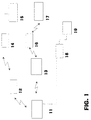
- FIG. 1 is a monitoring network, which consists of a central office 13, several Sub-centers 12, 14, 16, 18, a control unit 11 and the Surveillance camera units 15, 17 and 19 exist.
- control unit 11 shown in detail consists of a Display unit 21, a computing unit 22, input units 23, 24, 25 and a transmitting and receiving unit 26.
- the in FIG. 4 surveillance camera unit 17 shown in more detail consists of a camera unit 41, a positioning unit 44, a control unit 42 and a transmitting and receiving unit 43.
- the in FIG. 3 is shown in more detail in several areas divided up.
- the computing unit 22 controls and defines the display unit 21 on the display unit 21 a display area 31.
- this Display area 31 shows computing unit 22 one video signal at a time of the surveillance camera units 15, 17 or 19.
- About each one Control unit 23, 24, 25 can be any Surveillance camera units 15, 17, 19 selected and their current Video signal can be displayed.
- the leg units 23, 24, 25 are redundant.
- areas 32, 33, 34a, 34b are in the form of Scroll bars arranged on the edge of the display area 31.
- the surveillance camera unit 17 selected and their video signal is in the display area 31 of the Display unit 21 of the control unit 11 from the computing unit 22 of the Control unit 11 shown.
- the scroll bar 32 is at the bottom of the display area 31 Display unit 21 of the control unit 11 arranged and sets the horizontal Adjustment possibility of the positioning unit 44 of the Surveillance camera unit 17.
- the scroll bar 33 is on the left edge of the display area 31 of the display unit 21 of the control unit 11 arranged and provides the vertical adjustment of the Positioning unit 44 of the surveillance camera unit 17.
- Die Scroll bar 34a is on the right edge of the display area 31 Display unit 21 of the control unit 11 arranged and implemented in a visual Way the zoom option of the surveillance camera unit 17.
- Die Scroll bar 34b is also on the right edge of the display area 31 the display unit 21 of the control unit 11 arranged and implemented in visual way of focusing the surveillance camera unit 17.
- On the scroll bars 32, 33, 34a, 34b there are markings 35, 36, 37a, 37b arranged.
- marks 38 and 39 are in the Display area 31 of the display unit 21 of the control unit 11 is present.
- computing unit 22 at the same time displays multiple video signals from surveillance camera units.
- the camera unit 41 of the surveillance camera unit 17 detects one Part of the field of view to be monitored.
- the control unit 42 of the Surveillance camera unit 17 compresses the video signal of the Camera unit 41 of the surveillance camera unit 17 and the transmitting and Receiving unit 43 of surveillance camera unit 17 transmits this to the sub-center 16. This transmits the compressed video signal to the center 13, which the compressed video signal to the Control unit 11 transmitted.
- the transmit and receive Receiving unit 26 the compressed video signal and forwards it to the Computing unit 22 further.
- the computing unit 22 decompresses this Video signal and displays the video signal on the display unit 21 in Display area 31.
- To visualize the current settings of the Surveillance camera unit 17 transmits the control unit 42 of the Surveillance camera unit 17 after each change in the setting of the Positioning unit 44 of the surveillance camera unit 17 and / or the Zoomes and / or the focus of the camera unit 41 of the Surveillance camera unit 17 to the current setting data Control unit 11.
- the computing unit 22 evaluates this data and provides the current settings of the surveillance camera unit 17 via the Scroll bars 32, 33, 34a, 34b and the markings 35, 36, 37a, 37b in for is easily recognizable to the user.
- the scroll bar 32 with the marking 35 located on it represents the current positioning range of the surveillance camera unit 17, which can be defined within an entire positioning range, in the horizontal direction, regardless of how large the associated angle actually is.
- the marker 35 shows the current position of the surveillance camera unit 17 in the horizontal direction.
- the scroll bar 33 with the marking 36 located on it represents the positioning range of the surveillance camera unit 17, which can be defined within an entire positioning range, in the vertical direction, irrespective of how large the associated angle actually is.
- the marker 36 shows the current position of the surveillance camera unit 17 in the vertical direction.
- the scroll bar 34a with the marking 37a on it represents the entire adjustment range of the zoom setting of the surveillance camera unit 17, regardless of how large it is.
- the marking 37a shows the current setting of the zoom of the surveillance camera unit 17.
- the scroll bar 34b with the marking 37b located on it represents the entire adjustment range of the focusing of the surveillance camera unit 17, regardless of how large it is.
- the marking 37b shows the current setting of the focus of the surveillance camera unit 17.
- the computing unit 22 represents the marking 38 in the center of the display area 31. This visualizes the current center of the current scene captured by the surveillance camera unit 17.
- the computing unit 22 displays the marking 39 in the display area 31 of the display unit 21.
- the marking 39 is controlled by means of one of the input units 23, 24, 25 or more of the input units 23, 24, 25 and can be moved freely over the entire display area 31.
- the user of the control unit 11 receives the scene currently recorded by the surveillance camera unit 17 in the display area 31. If the orientation of the surveillance camera unit 17 is to be changed, the operator uses the input units 23, 24, 25 to control the marking 39 to that point on the display area 31 of the display unit 21 which is to be the new center of the scene. Once this selection has been made, it fixes the marking 39 via one of the input units 23, 24, 25 and the control unit 11 indicates the positioning of the surveillance camera unit 17 on the newly selected scene center. This is done in such a way that the computing unit 22 of the control unit 11 detects and calculates the distance between the markings 39 and 38 in the horizontal and vertical directions in the display area 31.
- the computing unit 22 detects the location values assigned to the markings 38 and 39 in the display area 31 and calculates the relative distance between the two markings. The calculation is carried out in relation to the image width and the image height of the display areas 31 of the display unit 21.
- the computing unit 22 of the control unit 11 compresses the determined distance data and transmits the distance data to the transmission and reception unit 26 of the control unit 11.
- the transmission and reception unit 26 transmits the data to the control center 13, which then sub-control center 16 and this conducts the compressed data to the surveillance camera unit 17. In the surveillance camera unit 17, these data are received by the transmitting and receiving unit 43, forwarded to the control unit 42 of the surveillance camera unit 17 and decompressed.
- the control unit 42 of the surveillance camera unit 17 calculates the absolute values for position control from these data and the current settings of the camera unit 41 of the surveillance camera unit 17, in particular the opening angle of the lens, and the positioning unit 44 of the surveillance camera unit 17.
- the control unit 42 of the surveillance camera unit 17 now controls the positioning unit 44 with the absolute data.
- the positioning unit 44 now moves the camera unit 41 into the new position at maximum speed.
- the video signals of the camera unit 41 continue to be in above described manner, transmitted to the control unit 11 and there on the Display unit 21 shown in the display area 31.
- the processing unit of the surveillance camera unit 17 calculates the computing unit 22 of the control unit 11 the new positioning of the markings 36 and 35 on the roller bars 33 and 32, based on the new position of the Surveillance camera unit 17.
- the user can use one of the input units 23, 24, 25 Positioning of the markings 35, 36 on the assigned Scroll bars 32, 33 move and thus the Surveillance camera unit 17 in a larger area than that Align display area 31.
- the mark 36 is on the scroll bar 33 moved all the way up, this evaluates the Computing unit 22 and transmits to surveillance camera unit 17 the command that the control unit 42 the positioning unit 44 with the Align camera unit 41 to the maximum vertical position still above.
- the marking 37a is moved on the scroll bar 34a.
- the marking 37a is selected via the input units 23, 24, 25 and postponed. In this way the zoom factor of the camera is increased or reduced.
- the image section is reduced or enlarged corresponding.
- the computing unit 22 detects the change in position the marking 37a on the scroll bar 34a to the previous position and determines a relative change in the marking to the previous one Position.
- This data about the relative change is transmitted by the Computing unit 22 via the transmission and reception unit 26 of the Control unit 11, via the center 13 and the sub-center 16 to the Surveillance camera unit 17.
- the transmitting and receiving unit 43 of the Surveillance camera unit 17 receives this data and guides it the control unit 42 of the surveillance camera unit 17.
- the Control unit 42 calculates the absolute data from the relative data Change the zoom of the camera unit 41 and represents the zoom of the Camera unit 41 to the new value.
- the Scroll bar 34b and mark 37b is on the Scroll bar 34b selected using one of the input units 23, 24, 25 and changed. The rest of the procedure corresponds to that for the zoom setting described procedure.
- the conversion of the relative data calculated by the computing unit 22 of the control unit 11 takes place in the control unit 42 of the surveillance camera unit 17 as follows:
- the relative data are calculated as the ratio of the current image width and image height of the display area 31 of the display unit 21 to the position of the marking 39 relative to the marking 38 on the display area 31 of the display unit 21.
- the width of the entire display area 31 is defined as 1, as is the height. If the marking 39 is changed, the new position of the marking 39 on the display area 31 of the display unit 21 of the control unit 11 can be specified in relation to the image width and height of the display area 31 and the marking 38 and in each case in a value range from -0.5 to +0.5 lie.
- the marking 39 is shifted from the marking 38 on the display area 31 to the top left onto a point of the display area 31 such that the ratio to the image width is -0.2 and the ratio to the image height is +0.3 by the computing unit 22 is determined, these values, namely -0.2 for the image width and +0.3 for the image height, are transmitted to the surveillance camera unit 17 as relative values.
- the control unit 42 of the surveillance camera unit 17 uses these relative data and the settings of the surveillance camera unit 17, in particular the opening angle of the lens, to calculate the new position values to which the positioning unit 44 of the surveillance camera unit 17 must be activated in order to assume the new position. In principle, this process also applies to zoom and focus.
- the track 32 is in shape a ring or an arc.
- this ring shows the Control unit 22 marks 35; the mark 35 is only on the Slidable ring. This creates the visual reference to the fact that the camera moves in a horizontal direction on a circular path because the Positioning unit 44 of surveillance camera unit 17 in a horizontal position Plane performs a circular movement and the camera unit 41 Surveillance camera unit 17 rotated and not linearly shifted.
- the scroll bar 33 and the scroll bar 32 applied a grid, which the absolute values of the Control shows in degrees-inclination angle. This is the user immediately clear at which point the camera is located.
- control unit 11 is replaced by a commercially available PC.
- the display unit 21 is formed by a screen monitor, the computing unit 22 is the CPU with memory, the transmitting and receiving unit 26 is implemented by a data interface and the input unit 23 by a mouse, the input unit 24 by a joystick and the input unit 25 by a commercially available one Keyboard. It is also conceivable to present the display unit 21 as a touch-sensitive screen, as a result of which the input units 23 to 25 can be dispensed with completely, since these are then directly integrated in the display unit 21.
- the camera control can also be used for automatic offender tracking.
- the user assigns an existing object, for example a person, to the marking 39 in the display area 31.
- the computing unit 22 analyzes the object, in particular the displayed shape of the object, and assigns the marking 39 to it, centered on the assigned object. If the object moves, this is determined by the computing unit 22.
- the computing unit 22 moves the marking 39 in accordance with the movement of the marked object. If the marking 39 moves, the computing unit 22 immediately calculates the relative change in the distance of the marking 39 from the marking 38 and transmits this data to the surveillance camera unit 17 in the manner described above.
- the surveillance camera unit guides the camera unit by means of the control unit 42 and the positioning unit 44 41 according to the object. In this way, the object is tracked continuously as long as it is in the area of the surveillance camera unit (visible area).
- the computing unit 22 recognizes the relative reduction in the size of the object and sends this relative data to the surveillance camera unit 17.
- the latter now controls the zoom and the focus based on the current settings of the camera unit 41 and the relative data, so that the object is displayed on the display area 31 in unchanged size and sharpness.
- the user able and detected by the surveillance camera unit 17 the scene shown in the display area 31 by means of one of the Input units 23, 24, 25 to zoom.
- the user defines one using one of the input units 23, 24, 25 rectangular area.
- the Computing unit 22 and the new display area 31 approaches, by giving the new relative data to the surveillance camera unit 17 transmitted.
- the control unit 42 of the surveillance camera unit 17 controls the camera unit 41 with the absolute setting data, calculated from the transferred relative data and the current settings of the Surveillance camera unit 17.
- the selected section is zoomed and shown in the display area 31 of the display unit 21.
- the Surveillance camera unit 15 wired to sub-center 14 connected.
- the sub-center 14 is, however, over a radio link with the Central 13 connected.
- the surveillance camera unit 19 is with the Sub-centers 18 connected via a line and the sub-center 18 is directly connected to the control unit 11.
- Surveillance camera unit to connect directly to the control unit 11. This causes the time delay in the transmission of the video signals the surveillance camera unit and in the transmission of the control data shortened. This makes real-time control easier.
- the Positioning unit 44 of surveillance camera unit 17 by a Swivel head or a so-called dome realized.
- the pan and tilt head and the dome have a serial interface Data transfer to.
- the Surveillance camera unit 17 equipped with an auto focus. Of the The focus automatically becomes the one currently being monitored by the surveillance camera unit 17 adapted scene.
- the Scroll bars 34a, 34b are automatically hidden if longer No changes in focus or zoom in the time period Surveillance camera unit 17 have been made.
Landscapes
- Engineering & Computer Science (AREA)
- Multimedia (AREA)
- Signal Processing (AREA)
- Human Computer Interaction (AREA)
- Closed-Circuit Television Systems (AREA)
- Studio Devices (AREA)
Abstract
Description
Die Erfindung betrifft eine Kamerasteuerung, insbesondere zur Steuerung der Bewegung einer Überwachungskamera mit den im Oberbegriff angegebenen Merkmalen.The invention relates to a camera control, in particular for control the movement of a surveillance camera with those in the preamble specified features.
Problematisch bei modernen Überwachungsanlagen mit Kamerasystemen und manueller Bewegungssteuerung der Überwachungskameras ist, daß die modernen Kamerasysteme mit sehr hohen Einstellgeschwindigkeiten arbeiten, welche die Fähigkeiten von Benutzern dieser Überwachungskameras überfordern. Dome oder Schwenk-Neigeköpfe mit seriellen Schnittstellen erreichen immer höhere Geschwindigkeiten und dadurch kürzere Einstellzeiten bei der Positionssteuerung. Bei der manuellen Steuerung durch einen Benutzer können zumeist diese hohen Geschwindigkeiten der Überwachungskamera nicht genutzt werden, weil sie mit den vorhandenen manuellen Bedienmitteln nicht beherrschbar sind.Problematic with modern surveillance systems with camera systems and manual motion control of the surveillance cameras is that the modern camera systems with very high setting speeds work which the skills of users of this Surveillance cameras overwhelmed. Dome or pan-tilt heads with serial interfaces reach ever higher speeds and therefore shorter response times for position control. In the manual control by a user can mostly these high Security camera speeds cannot be used because of them cannot be mastered with the existing manual controls.
Zumeist sind Überwachungskameras in ein Überwachungsnetz einbezogen, welches hierarchisch aufgebaut ist. Es existieren verschiedene Unterzentralen welche untereinander und mit der Zentrale, der Alarmzentrale, Daten austauschen. Über die Zentrale und die Unterzentralen wird der gesamte Datenverkehr abgewickelt, auch die manuelle Steuerung, die Positionssteuerung und die Videosignalübertragung der Überwachungskameras. Unter Positionssteuerung ist zu verstehen, daß die Überwachungskamera an in der Überwachungskamera gespeicherten Positionen Verfahren wird. Insbesondere bei der manuellen Steuerung entsteht ein Zeitversatz bei der Übertragung der Steuerbefehle und durch die Reaktionszeit des Benutzers. Wird eine manuelle Steuerung einer Überwachungskamera vorgenommen, so erfolgt, wegen des beschriebenen Zeitversatzes, ein verspätetes Ausführen des Stopp-Befehls. Es entsteht ein sogenannter Überlauf der Überwachungskamerabewegung. Dieser Überlauf nimmt mit der Versögerungsdauer der Befehlsübertragung, der Reaktionszeit des Benutzers und der Positioniergeschwindigkeit der Überwachungskamera zu. Im weiteren ist zu beachten, daß in einem digitalen Übertragungssystem, welches zumeist bei Überwachungsnetzen eingesetzt wird, das Videosignal der Überwachungskamera ebenfalls einer Zeitverzögerung unterliegt. Dies bedeutet, daß die von der Überwachungskamera erfaßte Szene stets einen Zeitvorsprung vor der Anzeige der Szene auf dem Überwachungsmonitor hat. Bei einer manuellen Steuerung der Überwachungskamera entsteht hierdurch ein weiterer Überlauf, da die Überwachungskamera stets weiter bewegt ist, als dies auf dem Überwachungsmonitor des Benutzers angezeigt wird.Surveillance cameras are mostly included in a surveillance network, which is hierarchical. There are several Sub-centers which with each other and with the central, the Alarm center, exchange data. Via the head office and the All data traffic is handled in sub-centers, including that manual control, position control and the Video signal transmission from the surveillance cameras. Under Position control is to be understood that the surveillance camera on in positions of the surveillance camera stored procedure. In the case of manual control in particular, there is a time lag in the Transmission of control commands and by the response time of the user. If a surveillance camera is controlled manually, thus, due to the time delay described, there is a delay Execution of the stop command. A so-called overflow occurs Surveillance camera movement. This overflow increases with the Delay in command transmission, reaction time of the User and the positioning speed of the surveillance camera. It should also be noted that in a digital transmission system, which is mostly used in surveillance networks, the video signal the surveillance camera is also subject to a time delay. This means that the scene captured by the surveillance camera is always one Time advantage before the scene is displayed on the surveillance monitor Has. With a manual control of the surveillance camera arises this causes a further overflow, since the surveillance camera always continues moved than this is displayed on the user's surveillance monitor becomes.
Aus US 4 720 805 ist bekannt, die Bewegung der Kamera durch die Bewegung der Hand, mittels eines Systems Tablett/Schreibstift oder eines Touch Screen wegeproportional und zeitgleich zu steuern. Nachteilig hierbei ist aber, daß die Bewegung, wie bei herkömmlicher manueller Steuerung mit Taten oder Joystick, nicht verzögerungsfrei erfolgt. Hierdurch kommt es zu einem Überlauf der Kamera. Große Geschwindigkeiten sind nicht handhabbar. From US 4 720 805 it is known that the camera moves through the Movement of the hand, using a tablet / pen system or Control the touch screen proportionally and simultaneously. The disadvantage here is that the movement, as with conventional manual control with Actions or joystick, not instantaneous. This is what happens an overflow of the camera. Great speeds are not manageable.
Aus Research Disclosure, Nr. 340, August 1992, Titel: ![]()
![]()
Aus WO 94/08424 ist ein Verfahren und eine Vorrichtung zur Steuerung einer Kamera bekannt. Hierbei wird auf einem Computerbildschirm das von der Kamera erfaßte Bildsignal dargestellt. Über eine Zeigereinheit wird auf dem Bildschirm ein Bildpunkt ausgewählt, welchen die Kamera ansteuern soll. Der Computer berechnet anschließend die Absolutwerte zur Kamerasteuerung und steuert auf diese Weise die Kamera an. Diese wird auf die neue Position verfahren. Nachteilig hierbei ist, daß die Daten zur Steuerung der Kamera als Absolutwerte übertragen werden. Hier müssen die aktuellen Einstellungsdaten der Kamera und des Objektivs im Computer vorhanden sein, um die Absolutdaten zur Kamerasteuerung zu berechnen. Die aktuellen Einstellungsdaten der Kamera und des Objektivs müssen folglich stets vor der Absolutdatenberechnung abgefragt werden und bekannt sein.WO 94/08424 describes a method and a device for control known to a camera. Here, on a computer screen, the image signal captured by the camera. A pointer unit is used to selected a pixel on the screen which the camera controls should. The computer then calculates the absolute values Camera control and controls the camera in this way. This will move to the new position. The disadvantage here is that the data for Control of the camera can be transferred as absolute values. Here must the current setting data of the camera and lens in the computer be available to calculate the absolute data for camera control. The current setting data of the camera and lens must be consequently always be queried before the absolute data calculation and be known.
Aufgabe der Erfindung ist es, eine Kamerasteuerung anzugeben, welche es ermöglicht, eine Überwachungskamera mit großer Zielgenauigkeit, auch bei Übertragungsverzögerungen, zu steuern. Im weiteren soll die Neupositionierung der Überwachungskamera mit kurzen Einstellzeiten erfolgen, die Positionssteuerung der Überwachungskamera soll leicht handhabbar sein und den Bediener entlasten. Es sollen zur Steuerung marktgängige, eingeführte Bedienelemente verwendet werden. Schließlich soll eine Kombination mit bekannten Bedienelementen möglich sein. Diese Aufgabe wird durch die Merkmale des Anspruchs 1 gelöst. Vorteilhafte Ausgestaltungen der Erfindung sind in den abhängigen Ansprüchen angegeben.The object of the invention is to provide a camera control which it enables a surveillance camera with great accuracy, even at Transmission delays to control. In the further the Repositioning of the surveillance camera with short response times done, the position control of the surveillance camera should be easy be manageable and relieve the operator. It's supposed to control commercially available, introduced controls are used. Finally a combination with known controls should be possible. This object is solved by the features of claim 1. Beneficial Embodiments of the invention are in the dependent claims specified.
Die Kamerasteuerung besteht aus einer Steuereinheit, welche sich aus einer
Recheneinheit, einer Anzeigeeinheit, einer Eingabeeinheit und einer Sende-Empfangseinheit
zusammensetzt. Im weiteren ist eine
Überwachungskameraeinheit in einem hierarchisch aufgebauten
Überwachungsnetzwerk vorhanden.
Das Überwachungsnetzwerk besteht beispielsweise aus einem Netzwerk
von Zentrale und Unterzentralen einer Alarmanlage, einem Telefonnetzwerk
auf digitaler Basis oder einem Kommunikationsnetz. Das
Kommunikationsnetz kann sowohl ein analoges, als auch ein digitales Netz:
seinThe camera control consists of a control unit, which is composed of a computing unit, a display unit, an input unit and a transceiver unit. Furthermore, there is a surveillance camera unit in a hierarchically structured surveillance network.
The monitoring network consists, for example, of a network of headquarters and sub-centers of an alarm system, a telephone network on a digital basis or a communication network. The communication network can be both an analog and a digital network
Die Überwachungskameraeinheit besteht aus einer Überwachungskamera, einer Positionierungseinheit, welche die Positionssteuerung der Überwachungskamera vornimmt, einer Steuereinheit und einer Sende- und Empfangseinheit.The surveillance camera unit consists of a surveillance camera, a positioning unit which controls the position of the Surveillance camera makes a control unit and a transmission and Receiving unit.
Die Überwachungskamera erfaßt die von ihr überwachte Szene. Die Videosignale der Überwachungskamera werden von der Steuereinheit der Überwachungskameraeinheit komprimiert und über die Sende- und Empfangseinheit der Überwachungskameraeinheit über das Überwachungsnetzwerk an die Steuereinheit der Kamerasteuerung übertragen. Die Steuereinheit der Kamerasteuerung empfängt das übertragenen Videosignal der Überwachungskamera und leitet es an die Recheneinheit weiter. Diese dekomprimiert das Videosignal und stellt es auf der Anzeigeeinheit dar. Im Bildmittelpunkt der Anzeigeeinheit ist eine Markierung angebracht, welche den Mittelpunkt des Anzeigebereiches der Anzeigeeinheit darstellt und zugleich die Mitte der von der Überwachungskameraeinheit aufgenommenen Szene bezeichnet. Im weiteren ist eine weitere Markierung auf der Anzeigeeinheit vorhanden. Diese Markierung ist einer der Eingabeeinheiten zugeordnet und wird mittels dieser Eingabeeinheit über den gesamten Anzeigebereich der Anzeigeeinheit bewegt. Die Markierung kann über den gesamten Anzeigebereich der Anzeigeeinheit verschoben werden. Über diese Markierung wählt ein Benuzter einen neuen Positionierpunkt der Überwachungskamera aus, indem er die Markierung an einen beliebigen Bildpunkt des Anzeigebereichs der Anzeigeeinheit verschiebt und durch Betätigung der Eingabeeinheit aktiviert. Die Recheneinheit errechnet anhand der auf der Anzeigeeinheit vorhandenen Bildinformationen den relativen Abstand zwischen den zwei Markierungen im Anzeigebereich der Anzeigeeinheit in horizontaler und vertikaler Richtung mit Bezug zur Breite und Höhe des Anzeigebereiches der Anzeigeeinheit und überträgt diese Relativdaten über die Sende- und Empfangseinheit an die Steuereinheit der Überwachungskamera. Die Daten werden vor der Übertragung von der Recheneinheit der Steuereinheit der Kamerasteuerung komprimiert. Die Steuereinheit der Überwachungskamera dekomprimiert und analysiert die übertragenen Relativdaten und rechnet diese in Absolutwerte zur Steuerung der Positionierungseinheit der Überwachungskamera um. Dies erfolgt anhand der aktuellen Einstellungen der Positionierungseinheit der Überwachungskamera, insbesondere unter Berücksichtigung des Objektiv-Öffnungswinkels. Anschließend steuert die Steuereinheit der Überwachungskamera die Positionierungseinheit mit den errechneten Absolutwerten an. Die Überwachungskamera wird mit maximaler Geschwindigkeit auf die neue Position ausgerichtet. Es erfolgt eine Auftrennung des Regelkreises Benutzer und Überwachungskamera. Ein direkter Einfluß auf den Bewegungsablauf bei der Positionierung der Überwachungskamera durch den Benutzer entfällt. Ein Überlauf wird vermieden.The surveillance camera captures the scene it is monitoring. The Video signals of the surveillance camera are from the control unit of the Surveillance camera unit is compressed and transmitted and Receiving unit of the surveillance camera unit via the Monitoring network to the control unit of the camera control transfer. The control unit of the camera control receives this transmitted video signal from the surveillance camera and passes it to the Computing unit further. This decompresses the video signal and sets it up of the display unit. In the center of the image of the display unit is a Marked attached, which is the center of the display area of the Display unit and at the same time the middle of the Security camera unit recorded scene referred. in the there is another mark on the display unit. This marker is assigned to one of the input units and is displayed using this input unit over the entire display range of Display unit moves. The marking can be made over the whole Display area of the display unit can be moved. About these A user selects a new positioning point Security camera by placing the marker on any one Pixel of the display area of the display unit shifts and through Activation of the input unit activated. The computing unit calculates based on the image information available on the display unit relative distance between the two marks in the display area of the Display unit in horizontal and vertical direction with respect to the width and height of the display area of the display unit and transmits them Relative data on the sending and receiving unit to the control unit of the Security Camera. The data is transferred from the Computing unit of the control unit of the camera control is compressed. The Control unit of the surveillance camera decompresses and analyzes the transferred relative data and calculates them in absolute values for control the positioning unit of the surveillance camera. this happens based on the current settings of the positioning unit of the Security camera, especially taking into account the lens opening angle. Then the control unit controls the Surveillance camera the positioning unit with the calculated Absolute values. The surveillance camera comes with maximum Speed aligned to the new position. There is one Separation of the control loop user and surveillance camera. A direct influence on the sequence of movements when positioning the Surveillance camera by the user is eliminated. An overflow will occur avoided.
Im weiteren wird die Erfindung anhand eines Ausführungsbeispiels mit FIG. 1 bis 4 beschrieben. Bei der nachfolgenden Beschreibung handelt es sich um eine beispielhafte Realisierung der Erfindung. Die Beschreibung hat rein beispielhaften Charakter.The invention is further illustrated by an embodiment with FIG. 1 to 4 described. The description below is an exemplary implementation of the invention. The description is pure exemplary character.
Es zeigt:
- FIG. 1
- eine schematische Darstellung eines Funkalarmnetzes mit Unterzentralen,
- FIG. 2
- einen schematischen Aufbau einer Steuereinheit;
- FIG. 3
- eine schematische Darstellung der Aufteilung der Bildoberfläche einer Anzeigeeinheit und
- FIG. 4
- einen schematischen Aufbau einer Überwachungskameraeinheit.
- FIG. 1
- 1 shows a schematic representation of a radio alarm network with sub-centers,
- FIG. 2nd
- a schematic structure of a control unit;
- FIG. 3rd
- a schematic representation of the division of the image surface of a display unit and
- FIG. 4th
- a schematic structure of a surveillance camera unit.
Bei der beispielhaften Ausführungsform gemäß FIG. 1 handelt es sich um
einen Überwachungsnetzwerk, welches aus einer Zentrale 13, mehreren
Unterzentralen 12, 14, 16, 18, einer Steuereinheit 11 und den
Überwachungskameraeinheiten 15, 17 und 19 besteht.In the exemplary embodiment according to FIG. 1 is
a monitoring network, which consists of a
Die in FIG. 2 näher dargestellte Steuereinheit 11 besteht aus einer
Anzeigeeinheit 21, einer Recheneinheit 22, Eingabeeinheiten 23, 24, 25 und
einer Sende- und Empfangseinheit 26.The in FIG. 2
Die in FIG. 4 näher dargestellte Überwachungskameraeinheit 17 besteht aus
einer Kameraeinheit 41, einer Positionierungseinheit 44, einer Steuereinheit
42 und einer Sende- und Empfangseinheit 43.The in FIG. 4
Die in FIG. 3 näher dargestellte Anzeigeeinheit 21 ist in mehrere Bereiche
aufgeteilt. Die Recheneinheit 22 steuert die Anzeigeeinheit 21 und definiert
auf der Anzeigeeinheit 21 einen Anzeigebereich 31. In diesem
Anzeigebereich 31 zeigt die Recheneinheit 22 das Videosignal jeweils einer
der Überwachungskameraeinheiten 15, 17 oder 19 an. Über jede einzelne
Bedieneinheit 23, 24, 25 kann jede vorhandenen
Überwachungskameraeinheiten 15, 17, 19 ausgewählt und deren aktuelles
Videosignal angezeigt werden. Die Bedeineinheiten 23, 24, 25 sind
redundant. Im weiteren sind Bereiche 32, 33, 34a, 34b in Form von
Bildlaufleisten am Rande des Anzeigebereiches 31 angeordnet.
In der weiteren Beschreibung ist die Überwachungskameraeinheit 17
ausgewählt und deren Videosignal wird im Anzeigebereich 31 der
Anzeigeeinheit 21 der Steuereinheit 11 von der Recheneinheit 22 der
Steuereinheit 11 dargestellt. The in FIG. 3 is shown in more detail in several areas
divided up. The
Die Bildlaufleiste 32 ist am unteren Rand des Anzeigebereiches 31 der
Anzeigeeinheit 21 der Steuereinheit 11 angeordnet und stellt die horizontale
Einstellmöglichkeit der Positionierungseinheit 44 der
Überwachungskameraeinheit 17 dar. Die Bildlaufleiste 33 ist am linken Rand
des Anzeigebereichs 31 der Anzeigeeinheit 21 der Steuereinheit 11
angeordnet und stellt die vertikale Einstellmöglichkeit der
Positionierungseinheit 44 der Überwachungskameraeinheit 17 dar. Die
Bildlaufleiste 34a ist am rechten Rand des Anzeigebereiches 31 der
Anzeigeeinheit 21 der Steuereinheit 11 angeordnet und realisiert in visueller
Weise die Zoommöglichkeit der Überwachungskameraeinheit 17. Die
Bildlaufleiste 34b ist ebenfalls am rechten Rand des Anzeigebereiches 31
der Anzeigeeinheit 21 der Steuereinheit 11 angeordnet und realisiert in
visueller Weise die Fokusiermöglichkeit der Überwachungskameraeinheit
17. Auf den Bildlaufleisten 32, 33, 34a, 34b sind Markierungen 35, 36, 37a,
37b angeordnet. Im weiteren sind Markierungen 38 und 39 im
Anzeigebereich 31 der Anzeigeeinheit 21 der Steuereinheit 11 vorhanden.The
In einer vorteilhaften Ausgestaltung der Erfindung ist vorgesehen, daß im
Anzeigebereich 31 der Anzeigeeinheit 21 die Recheneinheit 22 zeitgleich
mehrere Videosignale von Überwachungskameraeinheiten anzeigt.In an advantageous embodiment of the invention it is provided that in
Die Kameraeinheit 41 der Überwachungskameraeinheit 17 erfaßt einen
Teilbereich des zu überwachenden Sichtfeldes. Die Steuereinheit 42 der
Überwachungskameraeinheit 17 komprimiert das Videosignal der
Kameraeinheit 41 der Überwachungskameraeinheit 17 und die Sende- und
Empfangseinheit 43 der Überwachungskameraeinheit 17 übermittelt dieses
an die Unterzentrale 16. Diese übermittelt das komprimierte Videosignal an
die Zentrale 13, welche das komprimierte Videosignal weiter an die
Steuereinheit 11 übermittelt. In der Steuereinheit 11 empfängt die Sende- und
Empfangseinheit 26 das komprimierte Videosignal und leitet es an die
Recheneinheit 22 weiter. Die Recheneinheit 22 entkomprimiert das
Videosignal und stellt das Videosignal auf der Anzeigeinheit 21 im
Anzeigebereich 31 dar.The
Zur Visuallisierung der aktuellen Einstellungen der
Überwachungskameraeinheit 17 überträgt die Steuereinheit 42 der
Überwachungskameraeinheit 17 nach jeder Veränderung der Einstellung der
Positionierungseinheit 44 der Überwachungskameraeinheit 17 und/oder des
Zoomes und/oder des Fokuses der Kameraeinheit 41 der
Überwachungskameraeinheit 17 die aktuellen Einstellungsdaten an die
Steuereinheit 11. Die Recheneinheit 22 wertet diese Daten aus und stellt die
aktuellen Einstellungen der Überwachungskameraeinheit 17 über die
Bildlaufleisten 32, 33, 34a, 34b und die Markierungen 35, 36, 37a, 37b in für
den Benutzer leicht erkennbarer Form dar.To visualize the current settings of the
Die Bildlaufleiste 32 mit der auf ihr befindlichen Markierung 35 stellt den,
innerhalb eines gesamten Positionierbereichs definierbaren aktuellen
Positionierbereich der Überwachungskameraeinheit 17 in horizontaler
Richtung dar, unabhängig davon, wie groß der zugehörige Winkel
tatsächlich ist. Die Markierung 35 zeigt den aktuellen Positionierort der
Überwachungskameraeinheit 17 in horizontaler Richtung an.
Die Bildlaufleiste 33 mit der auf ihr befindlichen Markierung 36 stellt den,
innerhalb eines gesamten Positionierbereichs definierbaren
Positionierbereich der Überwachungskameraeinheit 17 in vertikaler Richtung
dar, unabhängig davon, wie groß der zugehörige Winkel tatsächlich ist. Die
Markierung 36 zeigt den aktuellen Positionierort der
Überwachungskameraeinheit 17 in vertikaler Richtung an.
Die Bildlaufleiste 34a mit der auf ihr befindlichen Markierung 37a stellt den
gesamten Verstellbereich der Zoomeinstellung der
Überwachungskameraeinheit 17 dar, unabhängig davon, wie groß dieser
tatsächlich ist. Die Markierung 37a zeigt die aktuelle Einstellung des Zooms
der Überwachungskameraeinheit 17.
Die Bildlaufleiste 34b mit der auf ihr befindlichen Markierung 37b stellt den
gesamten Verstellbereich der Fokusierung der Überwachungskameraeinheit
17 dar, unabhängig davon, wie groß dieser tatsächlich ist. Die Markierung
37b zeigt die aktuelle Einstellung des Fokus der
Überwachungskameraeinheit 17.
Im weiteren stellt die Recheneinheit 22 die Markierung 38 im Zentrum des
Anzeigebereiches 31 dar. Diese visualisiert den aktuellen Mittelpunkt der
von der Überwachungskameraeinheit 17 erfaßten aktuellen Szene.
Außerdem stellt die Recheneinheit 22 die Markierung 39 im Anzeigebereich
31 der Anzeigeeinheit 21 dar. Die Markierung 39 wird mittels einer der
Eingabeeinheiten 23, 24, 25 oder mehrerer der Eingabeeinheiten 23, 24, 25
gesteuert und kann über den gesamten Anzeigebereich 31 frei verschoben
werden.The
The
Furthermore, the
Der Benutzer der Steuereinheit 11 erhält die von der
Überwachungskameraeinheit 17 aktuell erfaßte Szene im Anzeigebereich 31
dargestellt. Soll die Ausrichtung der Überwachungskameraeinheit 17
verändert werden, so steuert der Bediener über die Eingabeeinheiten 23, 24,
25 die Markierung 39 an diejenige Stelle des Anzeigeberiches 31 der
Anzeigeeinheit 21, welche die neue Szenenmitte sein soll. Ist diese Auswahl
erfolgt, so fixiert er über eine der Eingabeeinheiten 23, 24, 25 die
Markierung 39 und die Steuereinheit 11 leutet das Positionieren der
Überwachungskameraeinheit 17 auf den neu ausgewählten
Szenenmittelpunkt ein. Dies erfolgt in der Weise, daß die Recheneinheit 22
der Steuereinheit 11 den Abstand zwischen den Markierungen 39 und 38 in
horizontaler und vertikaler Richtung im Anzeigebereich 31 erfaßt und
berechnet. Die Recheneinheit 22 erfaßt die, den Markierung 38 und 39
zugeordneten Ortswerte im Anzeigebereich 31 und berechnet den relativen
Abstand beider Markierungen zueinander. Die Berechnung erfolgt im
Verhältnis zur Bildbreite und der Bildhöhe des Anzeigebereiche 31 der
Anzeigeeinheit 21.
Die Recheneinheit 22 der Steuereinheit 11 komprimiert die ermittelten
Abstandsdaten und überträgt die Abstandsdaten an die Sende- und
Empfangseinheit 26 der Steuereinheit 11. Die Sende- und Empfangseinheit
26 überträgt die Daten an die Zentrale 13, diese an die Unterzentrale 16 und
diese leitet die komprimierten Daten an die Überwachungskameraeinheit 17
weiter. In der Überwachungskameraeinheit 17 werden diese Daten von der
Sende- und Empfangseinheit 43 empfangen, an die Steuereinheit 42 der
Überwachungskameraeinheit 17 weitergeleitet und entkomprimiert. Die
Steuereinheit 42 der Überwachungskameraeinheit 17 errechnet aus diesen
Daten und den aktuellen Einstellungen der Kameraeinheit 41 der
Überwachungskameraeinheit 17, insbesondere des Öffnungswinkels des
Objektivs, und der Positionierungseinheit 44 der
Überwachungskameraeinheit 17 die Absolutwerte zur Positionssteuerung.
Die Steuereinheit 42 der Überwachungskameraeinheit 17 steuert nunmehr
die Positionierungseinheit 44 mit den Absolutdaten an. Die
Positonierungseinheit 44 verfährt nun die Kameraeinheit 41 mit maximaler
Geschwindigkeit in die neue Position.The user of the
The
Zugleich werden weiterhin die Videosignale der Kameraeinheit 41, in oben
beschriebener Weise, an die Steuereinheit 11 übertragen und dort auf der
Anzeigeeinheit 21 im Anzeigebereich 31 dargestellt. Zugleich mit dem
Verfahren der Überwachungskameraeinheit 17 errechnet die Recheneinheit
22 der Steuereinheit 11 die neuen Positionierungen der Markierungen 36
und 35 auf den Laufleisten 33 und 32, bezogen auf die neue Position der
Überwachungskameraeinheit 17. At the same time, the video signals of the
Mittels einer der Eingabeeinheiten 23, 24, 25 kann der Benutzer die
Positionierung der Markierungen 35, 36 auf den zugeordneten
Bildllaufleisten 32, 33 verschieben und damit die
Überwachungskameraeinheit 17 in einem größeren Bereich als den
Anzeigebereich 31 ausrichten. Wird beispielsweise die Markierung 36 auf
der Bildlaufleiste 33 ganz nach oben verschoben, so wertet dies die
Recheneinheit 22 aus und überträgt an die Überwachungskameraeinheit 17
den Befehl, daß die Steuereinheit 42 die Positionierungseinheit 44 mit der
Kameraeinheit 41 auf die maximale vertikale Position noch oben ausrichtet.The user can use one of the
Um den Bildausschnitt 31, das heißt den Zoom der Kameraeinheit 41 zu
verändern, wird die Markierung 37a auf der Bildlaufleiste 34a verschoben.
Über die Eingabeeinheiten 23, 24, 25 wird die Markierung 37a angewählt
und verschoben. Auf diese Weise wird der Zoomfaktor der Kamera erhöht
oder verringert. Der Bildausschnitt verringert sich oder vergrößert sich
entsprechend. Die Recheneinheit 22 erfaßt die Veränderung der Position
der Markierung 37a auf der Bildlaufleiste 34a zur vorherigen Position und
ermittelt hieraus eine Relativveränderung der Markierung zur vorherigen
Position. Diese Daten über die relative Veränderung übermittelt die
Recheneinheit 22 über die Sende- und Empfangseinheit 26 der
Steuereinheit 11, über die Zentrale 13 und die Unterzentrale 16 an die
Überwachungskameraeinheit 17. Die Sende- und Empfangseinheit 43 der
Überwachungskameraeinheit 17 empfängt diese Daten und leitet diese an
die Steuereinheit 42 der Überwachungskamerainheit 17 weiter. Die
Steuereinheit 42 errechnet aus den Relativdaten die Absolutdaten zur
Veränderung des Zooms der Kameraeinheit 41 und stellt den Zoom der
Kameraeinheit 41 auf den neuen Wert ein. Around the
Muß die Bildschärfe nachgestellt werden, so erfolgt dies über die
Bildlaufleiste 34b und die Markierung 37b. Die Markierung 37b wird auf der
Bildlaufleiste 34b mittels einer der Eingabeeinheiten 23, 24, 25 angewählt
und verändert. Der übrige Ablauf entspricht dem bei der Zoomeinstellung
beschriebenen Ablauf.If the image sharpness has to be adjusted, this is done via the
Auf diese Weise wird der Regelkreis zwischen dem Benutzer und der
Positionierungseinheit 44 der Überwachungskameraeinheit 17 aufgetrennt.
Der Benutzer muß nicht mehr selbst die Bewegung der Kameraeinheit 41
der Überwachungskameraeinheit 17 über die Positionierungseinheit 44 der
Überwachungskameraeinheit 17 bis zum Stillstand aktiv steuern und
nachregeln. Der Soll-Ist-Wert-Vergleich wird nicht mehr vom Benutzer
getätigt, sondern die Steuereinheit 11 bzw. Überwachungskameraeinheit 17
führt dieses selbständig und nur am Ausführungsort durch. Der Benutzer
muß lediglich über die Markierung 39 oder die Markierungen 35, 36, 37a
oder 37b der Bildlaufleisten 32, 33, 34a oder 34b neue Ausrichtungspunkte
der Überwachungskameraeinheit 17 festlegen. Die Bewegung der
Kameraeinheit 41 erfolgt mit maximaler Geschwindigkeit der
Positioniereinheit 44. Ein Überlauf wird vermieden.In this way, the control loop between the user and the
Die Umrechnung der von der Recheneinheit 22 der Steuereinheit 11
errechneten Relativdaten erfolgt in der Steuereinheit 42 der
Überwachungskameraeineheit 17 wie folgt:
Die Relativdaten werden als Verhältnis der aktuellen Bildbreite und Bildhöhe
des Anzeigebereiches 31 der Anzeigeeinheit 21 zur Position der Markierung
39 gegenüber der Markierung 38 auf dem Anzeigebereich 31 der
Anzeigeeinheit 21 errechnet. Die Breite des gesamten Anzeigebereiches 31
wird als 1 definiert, ebenso die Höhe. Wird die Markierung 39 verändert, so
kann die neue Position der Markierung 39 auf dem Anzeigebereich 31 der
Anzeigeeinheit 21 der Steuereinheit 11 im Verhältnis zur Bildbreite und
Bildhöhe des Anzeigebereiches 31 und der Markierung 38 angegebene
werden und jeweils in einem Wertebereich von -0,5 bis +0,5 liegen. Wird die
Markierung 39 beispielsweise von der Markierung 38 ausgehend auf dem
Anzeigebereich 31 derart nach links oben auf einen Punkt des
Anzeigebereiches 31 verschoben, daß das Verhältnis zur Bildbreite mit -0,2
und das Verhältnis zur Bildhöhe mit +0,3 von der Recheneinheit 22 bestimmt
wird, so werden diese Werte, nämlich -0,2 für die Bildbreite und +0,3 für die
Bildhöhe als Relativwerte an die Überwachungskameraeinheit 17
übertragen. Die Steuereinheit 42 der Überwachungskameraeinheit 17
errechnet aus diesen Relativdaten und den Einstellungen der
Überwachungskameraeinheit 17, insbeondere des Öffnungswinkels des
Objektivs, die neuen Positionswerte, auf welche die Positionierungseinheit
44 der Überwachungskameraeinheit 17 angesteuert werden muß, um die
neue Position einzunehmen. Dieser Ablauf gilt prinzipiell auch für Zoom und
Fokus.The conversion of the relative data calculated by the
The relative data are calculated as the ratio of the current image width and image height of the
In einer vorteilhaften Ausgestaltungsmöglichkeit ist die Laufleiste 32 in Form
eines Ringes oder Kreisbogens realisiert. Auf diesem Ring zeigt die
Steuereinheit 22 die Markierung 35 an; die Markierung 35 ist nur auf dem
Ring verschiebbar. Hierdurch ist der visuelle Bezug dazu hergestellt, daß
sich die Kamera in horizontaler Richtung auf einer Kreisbahn bewegt, da die
Positioniereinheit 44 der Überwachungskameraeinheit 17 in horizontaler
Ebene eine Kreisbewegung ausführt und die Kameraeinheit 41 der
Überwachungskameraeinheit 17 gedreht und nicht linear verschoben wird. In an advantageous embodiment, the
In einer weiteren Ausgestaltungsmöglichkeit ist auf der Bildlaufleiste 33 und
der Bildlaufleiste 32 ein Raster aufgebracht, welches die Absolutwerte der
Steuerung in Grad-Neigungs-Winkel anzeigt. Hierdurch ist dem Benutzer
sofort deutlich, an welchem Punkt sich die Kamera befindet.In a further embodiment, the
In einer weiteren vorteilhaften Ausgestaltungsform der Erfindung ist die
Steuereinheit 11 durch einen handelsüblichen PC ersetzt. Die
Anzeigeeinheit 21 wird von einem Bildschirmmonitor gebildet, die
Recheneinheit 22 ist die CPU mit Speicher, die Sende- und Empfangseinheit
26 wird durch eine Datenschnittstelle realisiert und die Eingabeeinheit 23
durch eine Maus, die Eingabeeinheit 24 durch einen Joystick und die
Eingabeeinheit 25 durch eine handelsübliche Tastatur. Es ist auch denkbar,
die Anzeigeeinheit 21 als berührungssensitiven Bildschirm darzustellen,
wodurch die Eingabeeinheiten 23 bis 25 komplett entfallen können, da diese
dann in der Anzeigeeinheit 21 direkt integriert sind.
In einer modifizierten Ausgestaltung der Erfindung kann die
Kamerasteuerung auch zur automatischen Täterverfolgung eingesetzt
werden Hierzu weist der Benutzer der Markierung 39 im Anzeigebereich 31
ein vorhandenes Objekt, beispeilsweise eine Person, zu. Die Recheneinheit
22 analysiert das Objekt, insbesondere die angezeigte Form des Objektes
und weist diesem, jeweils auf das zugewiesene Objekt zentriert, die
Markierung 39 zu. Bewegt sich das Objekt, so wird dies von der
Recheneinheit 22 ermittelt. Die Recheneinheit 22 bewegt die Markierung 39
entsprechend der Bewegung des markierten Objekts. Im Fall einer
Bewegung der Markierung 39 errechnet die Recheneinheit 22 sofort die
relative Veränderung des Abstandes der Markierung 39 von der Markierung
38 und überträgt diese Daten in oben beschriebener Weise an die
Überwachungskameraeinheit 17. Die Überwachungskameraeinheit führt
mittels der Steuereinheit 42 und der Positionierungseinheit 44 die
Kameraeinheit 41 dem Objekt nach. Auf diese Weise wird das Objekt stetig
verfolgt, so lange es im Bereich der Überwachungskameraeinheit (sichtbarer
Bereich) ist. Entfernt sich das Objekt von der Überwachungskameraeinheit
17 und wird es auf dem Anzeigebereich 31 kleiner, so erkennt die
Recheneinheit 22 die relative Verkleinerung des Objektes und übersendet
diese Relativdaten an die Überwachungskameraeinheit 17. Diese regelt nun
den Zoom und den Fokus anhand der aktuellen Einstellungen der
Kameraeinheit 41 und den Relativdaten nach, sodaß das Objekt auf dem
Anzeigebereich 31 in unveränderter Größe und Schärfe angezeigt wird.In a further advantageous embodiment of the invention, the
In a modified embodiment of the invention, the camera control can also be used for automatic offender tracking. For this purpose, the user assigns an existing object, for example a person, to the marking 39 in the
In einer weiteren vorteilhaften Ausgestaltung der Erfindung ist der Benutzer
in der Lage die von der Überwachungskameraeinheit 17 erfaßte und auf
dem Anzeigebereich 31 dargestellte Szene mittels einer der
Eingabeeinheiten 23, 24, 25 zu zoomen. Auf dem Anzeigebereich 31
definiert der Benutzer mittel einer der Eingabeeinheiten 23, 24, 25 einen
rechteckigen Bereich. Sobald dieser Bereich definiert ist, errechnet die
Recheneinheit 22 den neuen Anzeigebereich 31 und zommt diesen heran,
indem sie der Überwachungskameraeinheit 17 die neuen Relativdaten
übermittelt. Die Steuereinheit 42 der Überwachungskameraeinheit 17 steuert
die Kameraeinheit 41 mit den absoluten Einstelldaten, errechnet aus den
übertragenen Relativdaten und den aktuellen Einstellungen der
Überwachungskameraeinheit 17. Der ausgewählte Ausschnitt wird gezoomt
und im Anzeigebereich 31 der Anzeigeeinheit 21 dargestellt.In a further advantageous embodiment of the invention, the user
able and detected by the
In einer weiteren vorteilhaften Ausgestaltung der Erfindung ist die
Überwachungskameraeinheit 15 leitungsgebunden mit der Unterzentrale 14
verbunden. Die Unterzentrale 14 ist hingegen über eine Funkstrecke mit der
Zentralen 13 verbunden. Die Überwachungskameraeinheit 19 ist mit der
Unterzentralen 18 über eine Leitung verbunden und die Unterzentrale 18 ist
direkt mit der Steuereinheit 11 verbunden. Es ist aber auch denkbar eine
Überwachungskameraeinheit direkt mit der Steuereinheit 11 zu verbinden.
Hierdurch wird die Zeitverzögerung bei der Übertragung der Videosignale
der Überwachungskameraeinheit und bei der Übertragung der Steuerdaten
verkürzt. Eine Echtzeitsteuerung ist hierdurch leichter möglich.In a further advantageous embodiment of the invention, the
In einer weiteren vorteilhaften Ausgestaltung der Erfindung ist die
Positionierungseinheit 44 der Überwachungskameraeinheit 17 durch einen
Schwenkneigekopf oder einen sogenannten Dom realisiert. Der
Schwenkneigekopf und der Dom weisen eine serielle Schnittstelle zur
Datenübertragung auf.In a further advantageous embodiment of the invention, the
In einer weiteren vorteilhaften Ausgestaltung der Erfindung ist die
Überwachungskameraeinheit 17 mit einen Autofokus ausgestattet. Der
Fokus wird automatisch der aktuell von der Überwachungskameraeinheit 17
erfaßten Szene angepaßt.In a further advantageous embodiment of the invention, the
In einer weiteren vorteilhaften Ausgestaltung der Erfindung werden die
Bildlaufleisten 34a, 34b automatisch ausgeblendet, wenn über eine längere
Zeitdauer hinweg keine Veränderungen am Fokus oder am Zoom der
Überwachungskameraeinheit 17 vorgenommen worden sind. In a further advantageous embodiment of the invention, the
In einer weiteren vorteilhaften Ausgestaltung der Erfindung ist vorgesehen,
daß alle Markierungen und alle Bildlaufleisten von der Recheneinheit 22 auf
dem Anzeigebereich 31 der Anzeigeeinheit 21 ausgeblendet werden, wenn
über eine vordefinierte Zeitspanne hinweg keine der Eingabeeinheiten 23,
24, 25 bedient wurde.In a further advantageous embodiment of the invention,
that all markings and all scroll bars from the
Claims (15)
dadurch gekennzeichnet,
characterized,
dadurch gekennzeichnet,
characterized,
dadurch gekennzeichnet,
characterized,
dadurch gekennzeichnet,
characterized,
dadurch gekennzeichnet,
characterized,
dadurch gekennzeichnet,
characterized by
dadurch gekennzeichnet,
characterized,
dadurch gekennzeichnet,
characterized,
dadurch gekennzeichnet,
characterized,
dadurch gekennzeichnet,
characterized,
dadurch gekennzeichnet,
characterized,
dadurch gekennzeichnet,
characterized,
dadurch gekennzeichnet,
characterized,
dadurch gekennzeichnet,
characterized,
dadurch gekennzeichnet,
characterized,
Applications Claiming Priority (2)
| Application Number | Priority Date | Filing Date | Title |
|---|---|---|---|
| DE19811286 | 1998-03-16 | ||
| DE19811286A DE19811286C2 (en) | 1998-03-16 | 1998-03-16 | Camera motion control |
Publications (2)
| Publication Number | Publication Date |
|---|---|
| EP0944259A2 true EP0944259A2 (en) | 1999-09-22 |
| EP0944259A3 EP0944259A3 (en) | 2000-08-02 |
Family
ID=7861017
Family Applications (1)
| Application Number | Title | Priority Date | Filing Date |
|---|---|---|---|
| EP99104240A Withdrawn EP0944259A3 (en) | 1998-03-16 | 1999-03-03 | Control of camera movement |
Country Status (3)
| Country | Link |
|---|---|
| EP (1) | EP0944259A3 (en) |
| JP (1) | JPH11331824A (en) |
| DE (1) | DE19811286C2 (en) |
Cited By (2)
| Publication number | Priority date | Publication date | Assignee | Title |
|---|---|---|---|---|
| EP1274231A2 (en) * | 2001-07-06 | 2003-01-08 | plettac AG | Method and device for controlling pan and tilt movements of a camera |
| EP1696383A2 (en) * | 2005-02-25 | 2006-08-30 | Psion Teklogix Systems Inc. | Automatic perspective distortion detection and correction for document imaging |
Families Citing this family (4)
| Publication number | Priority date | Publication date | Assignee | Title |
|---|---|---|---|---|
| DE19958634A1 (en) * | 1999-12-04 | 2001-06-21 | Alcatel Sa | Procedure for recognizing obstacles on railroad tracks |
| DE10033652A1 (en) * | 2000-07-11 | 2002-01-24 | Messer Griesheim Gmbh | Monitoring system for remote controlled inventory, has head office with evaluation unit that processes signal sequence of data from receiver to obtain actual state of inventory |
| DE10341125B4 (en) * | 2003-09-06 | 2005-09-01 | Jeromin, Günter E., Prof. Dr. | monitoring device |
| CN114670981B (en) * | 2022-03-24 | 2023-05-26 | 阿里云计算有限公司 | Method and apparatus for controlling camera |
Citations (6)
| Publication number | Priority date | Publication date | Assignee | Title |
|---|---|---|---|---|
| US4992866A (en) * | 1989-06-29 | 1991-02-12 | Morgan Jack B | Camera selection and positioning system and method |
| EP0529317A1 (en) * | 1991-08-22 | 1993-03-03 | Sensormatic Electronics Corporation | Surveillance system with master camera control of slave cameras |
| JPH06205409A (en) * | 1993-01-07 | 1994-07-22 | Canon Inc | Electronic equipment and its control method |
| WO1995011566A1 (en) * | 1993-10-20 | 1995-04-27 | Videoconferencing Systems, Inc. | Adaptive videoconferencing system |
| EP0714081A1 (en) * | 1994-11-22 | 1996-05-29 | Sensormatic Electronics Corporation | Video surveillance system |
| EP0729275A2 (en) * | 1995-02-24 | 1996-08-28 | Canon Kabushiki Kaisha | Image input system |
Family Cites Families (3)
| Publication number | Priority date | Publication date | Assignee | Title |
|---|---|---|---|---|
| US4720805A (en) * | 1985-12-10 | 1988-01-19 | Vye Scott R | Computerized control system for the pan and tilt functions of a motorized camera head |
| DE4233137C1 (en) * | 1992-10-02 | 1994-01-05 | Ibm | Method and device for controlling a camera |
| US5473369A (en) * | 1993-02-25 | 1995-12-05 | Sony Corporation | Object tracking apparatus |
-
1998
- 1998-03-16 DE DE19811286A patent/DE19811286C2/en not_active Expired - Lifetime
-
1999
- 1999-03-03 EP EP99104240A patent/EP0944259A3/en not_active Withdrawn
- 1999-03-15 JP JP11068106A patent/JPH11331824A/en not_active Withdrawn
Patent Citations (6)
| Publication number | Priority date | Publication date | Assignee | Title |
|---|---|---|---|---|
| US4992866A (en) * | 1989-06-29 | 1991-02-12 | Morgan Jack B | Camera selection and positioning system and method |
| EP0529317A1 (en) * | 1991-08-22 | 1993-03-03 | Sensormatic Electronics Corporation | Surveillance system with master camera control of slave cameras |
| JPH06205409A (en) * | 1993-01-07 | 1994-07-22 | Canon Inc | Electronic equipment and its control method |
| WO1995011566A1 (en) * | 1993-10-20 | 1995-04-27 | Videoconferencing Systems, Inc. | Adaptive videoconferencing system |
| EP0714081A1 (en) * | 1994-11-22 | 1996-05-29 | Sensormatic Electronics Corporation | Video surveillance system |
| EP0729275A2 (en) * | 1995-02-24 | 1996-08-28 | Canon Kabushiki Kaisha | Image input system |
Non-Patent Citations (1)
| Title |
|---|
| PATENT ABSTRACTS OF JAPAN vol. 018, no. 566 (E-1622), 28. Oktober 1994 (1994-10-28) & JP 06 205409 A (CANON INC), 22. Juli 1994 (1994-07-22) * |
Cited By (4)
| Publication number | Priority date | Publication date | Assignee | Title |
|---|---|---|---|---|
| EP1274231A2 (en) * | 2001-07-06 | 2003-01-08 | plettac AG | Method and device for controlling pan and tilt movements of a camera |
| EP1274231A3 (en) * | 2001-07-06 | 2004-06-30 | plettac AG | Method and device for controlling pan and tilt movements of a camera |
| EP1696383A2 (en) * | 2005-02-25 | 2006-08-30 | Psion Teklogix Systems Inc. | Automatic perspective distortion detection and correction for document imaging |
| EP1696383A3 (en) * | 2005-02-25 | 2006-10-11 | Psion Teklogix Systems Inc. | Automatic perspective distortion detection and correction for document imaging |
Also Published As
| Publication number | Publication date |
|---|---|
| JPH11331824A (en) | 1999-11-30 |
| DE19811286C2 (en) | 2003-06-26 |
| EP0944259A3 (en) | 2000-08-02 |
| DE19811286A1 (en) | 1999-09-23 |
Similar Documents
| Publication | Publication Date | Title |
|---|---|---|
| DE69835185T2 (en) | Camera control system | |
| WO2007104367A1 (en) | Video monitoring system | |
| DE112012005330B4 (en) | Method and apparatus for compensating for exceeding a desired field of view by a remote-controlled image capture device | |
| DE68929092T3 (en) | Crane safety device | |
| EP1614080A1 (en) | Monitoring device | |
| DE102015016848A1 (en) | System for central control of one or more cranes | |
| DE19811286C2 (en) | Camera motion control | |
| DE202020105870U1 (en) | Remote control device for a video camera | |
| DE10012629A1 (en) | Remotely controlled camera head swivel system has viewing area limitation device that controls head position in accordance with outer line of object to be avoided during viewing | |
| WO2006032552A1 (en) | Tracking camera control | |
| DE102006060904B4 (en) | Airport traffic information display system | |
| EP2898666B1 (en) | Client device for displaying images of a controllable camera, method, computer program and monitoring system comprising said client device | |
| DE10132929B4 (en) | Method and device for controlling pan-tilt movements of a camera | |
| EP1434184B1 (en) | Control of a multicamera system | |
| CN206210111U (en) | Mobile the disobeying of one kind stops capturing system | |
| DE10027136C2 (en) | Mobile system for creating a virtual display | |
| EP1296213A1 (en) | Method and apparatus for guiding an unmanned aerial vehicle | |
| EP2424225B1 (en) | Imaging system and method for detecting an object | |
| EP0851448B1 (en) | Configurable actuating unit for controlling electronic devices | |
| EP3826954B1 (en) | Remote-control arrangement, method for operating the remote-control arrangement, and computer product | |
| EP1460383B1 (en) | Camera system for a vehicle | |
| DE10141521C1 (en) | User information representation system has specific user information assigned to calculated position coordinates of image of environment provided by camera | |
| DE102021123234A1 (en) | TELEOPERATOR WORKSTATION | |
| DE10210949A1 (en) | Area-surveillance equipment includes both wide-angle and narrow angle cameras connected to display showing entire area with detailed, inset image | |
| DE202004017966U1 (en) | Remote control signal generation controller, especially for pivoting device, pointer, graphical surface etc, has hand control unit, evaluation unit for deriving control signal from detected relative displacement of reference signal |
Legal Events
| Date | Code | Title | Description |
|---|---|---|---|
| PUAI | Public reference made under article 153(3) epc to a published international application that has entered the european phase |
Free format text: ORIGINAL CODE: 0009012 |
|
| AK | Designated contracting states |
Kind code of ref document: A2 Designated state(s): AT BE CH DE DK ES FI FR GB GR IE IT LI NL PT SE |
|
| AX | Request for extension of the european patent |
Free format text: AL;LT;LV;MK;RO;SI |
|
| PUAL | Search report despatched |
Free format text: ORIGINAL CODE: 0009013 |
|
| AK | Designated contracting states |
Kind code of ref document: A3 Designated state(s): AT BE CH CY DE DK ES FI FR GB GR IE IT LI LU MC NL PT SE |
|
| AX | Request for extension of the european patent |
Free format text: AL;LT;LV;MK;RO;SI |
|
| 17P | Request for examination filed |
Effective date: 20010108 |
|
| AKX | Designation fees paid |
Free format text: AT BE CH DE DK ES FI FR GB GR IE IT LI NL PT SE |
|
| RAP1 | Party data changed (applicant data changed or rights of an application transferred) |
Owner name: FUNKWERK PLETTAC ELECTRONIC GMBH |
|
| 17Q | First examination report despatched |
Effective date: 20050203 |
|
| GRAP | Despatch of communication of intention to grant a patent |
Free format text: ORIGINAL CODE: EPIDOSNIGR1 |
|
| STAA | Information on the status of an ep patent application or granted ep patent |
Free format text: STATUS: THE APPLICATION IS DEEMED TO BE WITHDRAWN |
|
| 18D | Application deemed to be withdrawn |
Effective date: 20060210 |