EP0944768B1 - A graphical user interface system for steam turbine operating conditions - Google Patents
A graphical user interface system for steam turbine operating conditions Download PDFInfo
- Publication number
- EP0944768B1 EP0944768B1 EP97949739A EP97949739A EP0944768B1 EP 0944768 B1 EP0944768 B1 EP 0944768B1 EP 97949739 A EP97949739 A EP 97949739A EP 97949739 A EP97949739 A EP 97949739A EP 0944768 B1 EP0944768 B1 EP 0944768B1
- Authority
- EP
- European Patent Office
- Prior art keywords
- turbine
- figures
- user interface
- graphical user
- mollier
- Prior art date
- Legal status (The legal status is an assumption and is not a legal conclusion. Google has not performed a legal analysis and makes no representation as to the accuracy of the status listed.)
- Expired - Lifetime
Links
Images


Classifications
-
- F—MECHANICAL ENGINEERING; LIGHTING; HEATING; WEAPONS; BLASTING
- F01—MACHINES OR ENGINES IN GENERAL; ENGINE PLANTS IN GENERAL; STEAM ENGINES
- F01K—STEAM ENGINE PLANTS; STEAM ACCUMULATORS; ENGINE PLANTS NOT OTHERWISE PROVIDED FOR; ENGINES USING SPECIAL WORKING FLUIDS OR CYCLES
- F01K13/00—General layout or general methods of operation of complete plants
- F01K13/02—Controlling, e.g. stopping or starting
-
- F—MECHANICAL ENGINEERING; LIGHTING; HEATING; WEAPONS; BLASTING
- F01—MACHINES OR ENGINES IN GENERAL; ENGINE PLANTS IN GENERAL; STEAM ENGINES
- F01D—NON-POSITIVE DISPLACEMENT MACHINES OR ENGINES, e.g. STEAM TURBINES
- F01D21/00—Shutting-down of machines or engines, e.g. in emergency; Regulating, controlling, or safety means not otherwise provided for
- F01D21/12—Shutting-down of machines or engines, e.g. in emergency; Regulating, controlling, or safety means not otherwise provided for responsive to temperature
-
- G—PHYSICS
- G05—CONTROLLING; REGULATING
- G05B—CONTROL OR REGULATING SYSTEMS IN GENERAL; FUNCTIONAL ELEMENTS OF SUCH SYSTEMS; MONITORING OR TESTING ARRANGEMENTS FOR SUCH SYSTEMS OR ELEMENTS
- G05B15/00—Systems controlled by a computer
Definitions
- temperature measuring devices are installed at the respective stages of the HP and LP casings. These measurements provides an indication to the operator or supervising engineer in charge whenever the blade temperature exceeds its limit.
- EP 0389132 discloses a control system for an industrial plant, a display device for such a control system and a method of controlling an industrial plant.
- the control system receives plant data and combines this with a number of graphical representations for display. If a user of the system wants to simplify the displayed information, then the control system has means for modifying the displays, and displaying that modified display. This means that various levels of plant information may be presented, depending upon the preferences of the user.
- the present invention is intended to be practiced preferrably with the application of a programmable computer.
- a method for blade temperature estimation in a steam turbine utilizes measurement values including pressure and temperature at locations other than directly at the blades, principally at the input and output stages.
- blade temperature is simulated by using a water/steam cycle analysis program as well as by directed experiments.
- An artificial neural network (ANN) is trained by presenting the measurement values and the blade temp values. In a present exemplary embodiment, it is found that 4 values provide a satisfactory result. In one method the ANN is used directly to derive operating blade temp values.
- a hybrid approach 5 measured values are utilized.
- a subset of, for example, 4 parameter values is used for training the ANN and another subset of, for example, 3 values is used for performing a calculation for another intermediate parameter.
- a blade temperature is calculated.
- the user interface provides a real-time information display for a supervising engineer in charge of turbine operation so that critical parameter values and undesirable combinations of operating conditions are readily observed and deviations are made apparent so that corrective action can be initiated rapidly. While graph plots of parameters can be readily presented, such a format generally does not readily provide an overall picture of the state of the turbine with regard to the distribution and combination of temperature, pressure, steam wetness or superheat, and turbulence effects.
- an overview of the operating situation is made more readily apparent by representing the operating expansion and compression processes by lines on a Mollier enthalpy/entropy chart.
- real-time parameter values and parameter trends are also presented.
- the supervising engineer can more quickly identify and correct undesirable and potentially troublesome operation conditions.
- a system utilizes a hybrid ANN (artificial neural network)-algorithmic based scheme for estimating the blade temperature from other measurements which are commonly available.
- the commonly available measurement values are herein utilized.
- the training data for the ANN includes both data generated by mathematical model and by experiment.
- the windage modules for HP and LP turbines in accordance with the present invention will provide the operator with an estimation of the blade temperature at the respective turbine stages.
- the interactive user interface herein disclosed displays the real-time value, a trend graph of these values, and the respective states within the Mollier diagram. Supervisory recommendation may be deduced from the estimation and other available measurement values.
- On-line visualization of the expansion/compression lines is especially beneficial for other parts of the turbine which are subject to overheating, due, in the present particular case, to the windage phenomenon.
- the LP turbine For heating steam turbines when the control valves, for example, in the cross over line for the two lower heaters are closed, the LP turbine requires cooling steam to hold within permissible limits the temperature rise caused by windage in the last stage. In this operating mode, the steam in the LP turbine absorbs energy resulting from the windage losses which predominate significantly within the last stages.
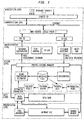
- DIGEST is a modular monitoring system for power system plant developed by the KWU-FTP activity of Siemens Aktiengesellschaft, (Simens AG), a corporation of Germany. DIGEST features a modular system architecture which can be divided into six different levels which will be explain briefly below. The module components are written in C, with much flexibility in building any structure of choice.
- the proposed windage module system architecture is shown in Figure 1.
- the first two levels are already available as part of DIGEST. Modifications were done to the administrative and data levels. Modifications in both the communication and data levels include parameter specification which is needed for requesting the module-specific data through the data bus,and for creating the data server and data base.
- the main windage module development is done mainly at the action and presentation levels.
- the six levels in the windage module are:
- the information is presented in several layers starting with the main windage screen which will mainly show the blade temperatures.
- the subsequent layers will show the detail conditions for each turbine section. These layers will provide information on all parameter values which are relevant to the operator for making appropriate decisions concerning the turbine operation. Further detail on the process within this level is provided in the following sections. detail in the next section.
- a development screen is optionally provided for accessing some internal module and system parameters or processes; however, principally because of security reasons, this feature may preferrably be omitted in an actual working version.
- the monitoring process may not always be necessary to cycle at the same rate at all times; it should depend on the turbine operating conditions. Several scenarios can be pre-determined for each specific turbine. For example, no load, full load, and low load during slow shutdown, start-up, and load rejection.
- the monitoring cycle should be adjusted automatically for different conditions, depending on their criticalities, and the respective display may be arranged to pop-up to assist the operator.
- the windage module basically has two main processes, the background process and the interactive display process.
- the background process is responsible for obtaining the necessary parameter values, calculating the blade temperature at a predefine rate, and recording the relevant information into the appropriate shared memory and data base.
- the interactive display process will show the necessary or requested information graphically at any point of time. The process rate is limited by the minimum amount of time required before all measurements stabilize, and will vary based on the severity of the turbine condition. Operation near the critical blade temperature may require faster process rate.
- the training sub-structure is responsible for producing the appropriate weights and parameters that will be used in the monitoring module. This process is done off-line and is not controllable through the GUI interface.
- the network is trained using the simulated data obtained by computing the estimated temperature using the analytical means for the expected normal operating domain, and actual data obtain from field experiments. The experiments concentrate on generating data in specific low steam flow conditions, such as shutdowns, loss of loads, and start-ups. This arrangement is expected to be able to estimate the blade temperature for the entire turbine operating ranges.
- Minimal inputs to the estimator are the real-time measurement values of the pressure of the main steam, temperature of the main steam, pressure of the third stage and exhaust pressure. Additional inputs can be optionally provided and evaluated.
- the background process will obtain measurement data, calculate the blade temperature and other necessary values, and store those values in appropriate locations.
- the process sequences are as follows:
- Preprocess incoming data into the desired format (interpreter). This process basically reads the incoming data string and reformat it to a standard ASCII format.
- the estimator will calculate the blade temperature value using the measurement values.
- the input measurment values used for estimating the blade temperature, at least for the HP turbine, are:
- the blade temperature estimation and other measurement parameters are then stored in two different places: the Data Base and intermediate Shared Memory.
- Figure 3 shows the general traning process which applicable to the ANN-module either in the direct approach or the hybrid approach. The only difference is in the input-parameters as indicated in the background process. The process can be described as follows:
- the first step is data construction which basically combines the data obtained from simulation using water/steam cycle analysis and data obtained from the experiments.
- Such analysis is for example included in thermodynamics modules within the DIGEST system.
- the water/steam cycle analysis is used inside the themodynamic module in the DIGEST system.
- the DIGEST monitoring system is currently available in the market through SIEMENS AG.
- the data is re- formatted such it matches the input format of the ANN.
- the data is then reorganized by separating the data into two separate data files where one is used for training and validation purposes, and one for testing purposes. Although there is no certain rule for regrouping the available data, data should be reorganized such that all operating regions should be well represented. In accordance with the present exemplary embodiment, 80% of the available data is utilized for training and validation and the rest for testing.
- the ANN structure is a standard multilayer, with 1 hidden layer.
- the number of hidden units may vary from 4 to 10 without significant improvement in performance: a longer traning period is needed for larger number of hidden units, and it may run the risk of overfitting.
- the ANN parameters connection weights and unit's threshold values
- the training parameters must be modified until a solution is obtained.
- the solutions are then tested using the data test file.
- the solution with the smallest error will be used in the estimation process during the background process.
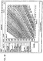
- the graphical user interface will also able to show the turbine conditions within the steam behavior Mollier diagram.
- This diagram also called a Mollier chart, enthalpy/entropy diagram, or a total heat/entropy diagram, serves as a familiar environment for any thermodynamics engineer and a better representation of the turbine condition with respect to all known critical operating boundaries. Therefore, this on-line turbine condition visualization will better help a user in taking appropriate control actions.
- GUI process must be initiated by the user. It will access values stored by the background process as required.
- the GUI process follows the following steps (see the correponding illustration in Figure 4).
- the Windage Graphical User Interface Module can be initiated independently or from within DIGEST. This will automatically initiate the connection to the Shared Memory unit.
- the shared memory unit is basically a routine which manages the access and transfer of data between the GUI and any process outside it, which mainly includes a buffer.
- the turbine overview window' gives the current value of the blade temperature, as well as other information which may be important for the user to make any decision concerning the control of the turbine.
- the Mollier diagram is generated based on the standard thermodynamic calculation available on any thermodynamic text book such as the afore-mentioned books.
- a routine is herein used which will generate the background Mollier grid, and then overlay the expansion data which are calculated from the current measurement values on top of the grid.
- such a routine is available from Siemens AG in VISUM, a user manual, Version 3, October 1992.
- the trend diagram allows the selection of up to ten parameters to be shown at the same time.
- the maximum number of parameters that can be shown is essentially unlimited; however, any number larger than ten will cause difficulties in viewing the graph itself. It has the same feature as feature #2 in the Mollier diagram.
- the exact value within a graph can be found by clicking on the desired point. The exact value will be displayed under the corresponding axis.
- the user can further analyze the data by selecting the 'FREE GRAPHICS' which will give the user access to the complete data base. This component is provided within the DIGEST system.
- the GUI display process will access the necessary data from the Shared Memory, with the exception of the FREE GRAPHICS routines which will access data from the data base through the data server.
Description
- In the operation of steam turbines, as for turbo-generators, it is important that operating parameters be kept within defined limits for proper and safe operation, including start-up and shut-down phases. Unsafe operation can have grave consequences for personal injury and material damage.
- Reference is hereby made to an application by the present inventors being filed concurrently herewith and entitled A METHOD FOR BLADE TEMPERATURE ESTIMATION IN A STEAM TURBINE whereof the disclosure is incorporated herein to the extent it does not conflict with the present application.
- Typically, in steam turbo-generator operations, the turbine was operated around full power or, when the demand for power was insufficient, it was shut down. Particularly in operation as part of a large power grid, operation at less than full load may be required. Under such conditions, complex patterns of temperature, pressure, steam wetness, reheating, expansion and compression, may occur, possibly resulting in excessive turbine blade temperature. Such conditions may spell blade failure with possibly disastrous consequences. Thus, monitoring operation under conditions where the intake steam pressure is at or lower than the output pressure are of practical importance. Background material is available in books such as W. W. Bathie, "Fundamentals of gas turbines", John Wiley and Sons, 1996; and H. Herlock, "Axial flow turbines: Fluid mechanics and thermodynamics", Butterworth, London, 1960.
- Good mathematical models for simulating the steam behavior in a turbine in its entire operating domain are not readily available, especially concerning periods in which the main-steam pressure is near or lower than the exhaust pressure. During such periods, the fluid flow behavior is very complex because the radial component of velocity become significant as compared with the axial velocity component. The available simplified mathematical models for simulating the steam behavior during normal loading typically do not perform properly when the intake pressure is near or lower than the output pressure.
- In new large steam turbines, temperature measuring devices are installed at the respective stages of the HP and LP casings. These measurements provides an indication to the operator or supervising engineer in charge whenever the blade temperature exceeds its limit.
- EP 0389132 discloses a control system for an industrial plant, a display device for such a control system and a method of controlling an industrial plant.
- The control system receives plant data and combines this with a number of graphical representations for display. If a user of the system wants to simplify the displayed information, then the control system has means for modifying the displays, and displaying that modified display. This means that various levels of plant information may be presented, depending upon the preferences of the user.
- The need for blade temperature monitoring for smaller and older turbine, as well as a more practical and cost effective ways than installing temperature probes, has led to a need, herein recognized, for a practical system for estimating in real time and monitoring turbine blade temperature during operation.
- The present invention is intended to be practiced preferrably with the application of a programmable computer.
- In accordance with an aspect of the invention, a method for blade temperature estimation in a steam turbine utilizes measurement values including pressure and temperature at locations other than directly at the blades, principally at the input and output stages. Initially, blade temperature is simulated by using a water/steam cycle analysis program as well as by directed experiments. An artificial neural network (ANN) is trained by presenting the measurement values and the blade temp values. In a present exemplary embodiment, it is found that 4 values provide a satisfactory result. In one method the ANN is used directly to derive operating blade temp values.
- In a accordance with another aspect of the invention, a hybrid approach, 5 measured values are utilized. A subset of, for example, 4 parameter values is used for training the ANN and another subset of, for example, 3 values is used for performing a calculation for another intermediate parameter. Using the intermediate parameter and one of the 5 measured values, a blade temperature is calculated.
- In accordance with still another aspect of the invention, the user interface provides a real-time information display for a supervising engineer in charge of turbine operation so that critical parameter values and undesirable combinations of operating conditions are readily observed and deviations are made apparent so that corrective action can be initiated rapidly. While graph plots of parameters can be readily presented, such a format generally does not readily provide an overall picture of the state of the turbine with regard to the distribution and combination of temperature, pressure, steam wetness or superheat, and turbulence effects.
- In accordance with the present invention, an overview of the operating situation is made more readily apparent by representing the operating expansion and compression processes by lines on a Mollier enthalpy/entropy chart. In combination, real-time parameter values and parameter trends are also presented. Using the Mollier chart information in conjunction with trend and real-time information, the supervising engineer can more quickly identify and correct undesirable and potentially troublesome operation conditions.
- In accordance with an aspect of the present invention, a system utilizes a hybrid ANN (artificial neural network)-algorithmic based scheme for estimating the blade temperature from other measurements which are commonly available. The commonly available measurement values are herein utilized. The training data for the ANN includes both data generated by mathematical model and by experiment.
- The invention will be better understood from the following detailed description in conjunction with the drawing, in which
- Figure 1 shows a windage module architecture in accordance with the invention;
- Figure 2 shows an artificial neural network based scheme for blade temperature estimation in accordance with the invention;
- Figure 3 shows a training procedure for an artificial neural network in accordance with the invention;
- Figure 4 shows graphical user interface structures applicable in conjunction with the invention; and
- Figure 5 shows graphical interface views applicable in conjunction with the invention.
-
- During the operation of the steam turbine, heating due to windage must be maintained within allowable limits by the operating mode. The windage modules for HP and LP turbines in accordance with the present invention will provide the operator with an estimation of the blade temperature at the respective turbine stages. The interactive user interface herein disclosed displays the real-time value, a trend graph of these values, and the respective states within the Mollier diagram. Supervisory recommendation may be deduced from the estimation and other available measurement values.
- In the following, examples of the windage phenomenon are given. In the HP turbine, as there is no steam flow through the turbine following a trip, the extent of energy transfer depends on the pressure and the steam density in the turbine. At a full load trip, the corresponding high cold reheater pressure will initially be present. In order to avoid impermissible heating by windage losses, an adequate pressure decay or a certain cooling steam flow is required. The expansion lines in the Mollier diagram indicate the advantage of a sufficient HP turbine flow after full load rejection to zero load. The operator is much better informed by such a figure.
- On-line visualization of the expansion/compression lines is especially beneficial for other parts of the turbine which are subject to overheating, due, in the present particular case, to the windage phenomenon. For heating steam turbines when the control valves, for example, in the cross over line for the two lower heaters are closed, the LP turbine requires cooling steam to hold within permissible limits the temperature rise caused by windage in the last stage. In this operating mode, the steam in the LP turbine absorbs energy resulting from the windage losses which predominate significantly within the last stages.
- In general the windage module will follow the system architecture used in a system known as the DIGEST system. DIGEST is a modular monitoring system for power system plant developed by the KWU-FTP activity of Siemens Aktiengesellschaft, (Simens AG), a corporation of Germany. DIGEST features a modular system architecture which can be divided into six different levels which will be explain briefly below. The module components are written in C, with much flexibility in building any structure of choice.
- The proposed windage module system architecture is shown in Figure 1. The first two levels are already available as part of DIGEST. Modifications were done to the administrative and data levels. Modifications in both the communication and data levels include parameter specification which is needed for requesting the module-specific data through the data bus,and for creating the data server and data base. The main windage module development is done mainly at the action and presentation levels.
- As indicated in Figure 1, the six levels in the windage module are:
- 1. Acquisition level. This level manages the data
acquisition process, which comoprises several
programmable logic controllers (PLC) 2 of the
type Siemens Simatic 5. Documentation onSimatic 5 is available from Siemens Industrial Automation. Its capabilities include signal sampling, A/D conversion, limited computation, executing sequence process action, cycle timing, and open communication functions. It is used in this context as a data acquisition device where it samples the measurement data at a predetermined rate, digitizes it and transfers the data through the ethernet network asynchronously. - 2. Communication level. This level basically is
the
communication server 6 which manages the transfer of information between the network and the DEC (Digital Equipment Corporation) digital workstation machine(s). The standard DEC module that handles the communication issue is called Omni-Server/DECnet PhaseV. The processes within the DEC which manage the the data transfer are indicated by DEC-55, 8, and S5-DEC, 10. DEC-S5 manages the data transfer from the adminstrative level to the S5, and S5-DEC manages data transfer from the S5 to the adminstrative level. - 3. Adimistration level. An administration level
of control handles the data request from the windage
process control by propagating the request in the
right format to a communication level, which is done
by a
telegram distributor module 12. It also manages the incoming data in a certain format and forwards the data back to the process control for storage. This is done by a telegram receiver module 14. Other functions include managing the buffer capacity (de-log), 16, self checking process (watchdog), 18, and several timers/clocks for interrupt purposes (time-control), 20. Self checking process is mainly to check the status of all processes within the system, and re-boot the system if necessary. - 4. Action level. The action level controls the continuous background process and computation. These include the initiation of data request (sending RQTs), management of incoming data (RDTs), data storage, all computation processes, and storage of results. A more detail description of this level can be found in the next section. This level may also include the output management which test the validity of the computation result. In this scheme the results of the hybrid artificial neural network (ANN) estimator are always compared to the result of the analytical module. This verification is required to detect possible bad results which are usually caused by input values which are far away from all samples that had been presented during the ANN training period. Large discrepancies may indicate that further re-training is in order.
- 5. Data level. The data level handles all processes concerning data storage and access. It includes the data server 22 and data base 24. All access to the data base must be done through the data server 22. Once the data is stored in the right format into the database 24, it can be accessed easily by all levels.
- 6. Presentation level. The presentation level provides a graphical user interface which allow the users to view all the necessary information in several different fashions, that is, current values, trend diagram and Mollier diagram. It consist of the Windage Graphical User Inteface 26, Free Graphics 28, and shared memory 30 for storing the intermediate parameter values needed for the user interface. The free graphics is an independent graphical tool for plotting any parameter values stored in the data base. This tool is developed as a part of the original DIGEST system.
-
- The information is presented in several layers starting with the main windage screen which will mainly show the blade temperatures. The subsequent layers will show the detail conditions for each turbine section. These layers will provide information on all parameter values which are relevant to the operator for making appropriate decisions concerning the turbine operation. Further detail on the process within this level is provided in the following sections. detail in the next section. A development screen is optionally provided for accessing some internal module and system parameters or processes; however, principally because of security reasons, this feature may preferrably be omitted in an actual working version.
- The monitoring process may not always be necessary to cycle at the same rate at all times; it should depend on the turbine operating conditions. Several scenarios can be pre-determined for each specific turbine. For example, no load, full load, and low load during slow shutdown, start-up, and load rejection. The monitoring cycle should be adjusted automatically for different conditions, depending on their criticalities, and the respective display may be arranged to pop-up to assist the operator.
- The windage module basically has two main processes, the background process and the interactive display process. The background process is responsible for obtaining the necessary parameter values, calculating the blade temperature at a predefine rate, and recording the relevant information into the appropriate shared memory and data base. The interactive display process will show the necessary or requested information graphically at any point of time. The process rate is limited by the minimum amount of time required before all measurements stabilize, and will vary based on the severity of the turbine condition. Operation near the critical blade temperature may require faster process rate.
- Before the monitoring process, the ANN must be trained. The training sub-structure is responsible for producing the appropriate weights and parameters that will be used in the monitoring module. This process is done off-line and is not controllable through the GUI interface. The network is trained using the simulated data obtained by computing the estimated temperature using the analytical means for the expected normal operating domain, and actual data obtain from field experiments. The experiments concentrate on generating data in specific low steam flow conditions, such as shutdowns, loss of loads, and start-ups. This arrangement is expected to be able to estimate the blade temperature for the entire turbine operating ranges. Minimal inputs to the estimator are the real-time measurement values of the pressure of the main steam, temperature of the main steam, pressure of the third stage and exhaust pressure. Additional inputs can be optionally provided and evaluated.
- The background process will obtain measurement data, calculate the blade temperature and other necessary values, and store those values in appropriate locations. The process sequences are as follows:
- Request the necessary measurement data to Acquisition Level through the Communication (using DEC-S5 protocol) and Administrative Levels (telegram distributor).
- Receive measurement data from data acquisition
system Simatic 5 (Siemens PLC). The request is
propagated through the ethernet network,
communicated using the S5-DEC protocol, and managed
by the tele-capture within the admistrative level.
The list of the measurement parameters include:
- Pms = Pressure of main steam (bar),
- Tms = Temperature of main steam (°C),
- P1 = Steam pressure before blading (bar),
- T1 = Steam temperature before blading (°C),
- P3 = Pressure at the third stage
- Pex = Exhaust pressure after reheater (bar)
- Peh = Exhaust pressure before reheater (bar),
- Teh = Exhaust temperature before reheater (°C),
- Tcb = Bottom casing temperature (°C),
- Tcu = Upper casing temperature (°C),
- Tci = Inside casing temperature (°C),
- Tco = Outside casing temperature (°C),
- N = Rotational speed (RPM)
- Pout = Output power (MW).
-
- Preprocess incoming data into the desired format (interpreter). This process basically reads the incoming data string and reformat it to a standard ASCII format.
- Store data in the intermediate files for futher processing.
- The estimator will calculate the blade temperature value using the measurement values. The input measurment values used for estimating the blade temperature, at least for the HP turbine, are:
- 1. Pressure of the main steam (Pms),
- 2. Temperture of the main steam (Tms),
- 3. Pressure at the third stage (P3rd), and
- 4. Exhaust pressure (Pex).
- 5. Rotational speed.
-
- One approach directly estimates the blade temperature using a straightforward 3 layer ANN, Figure 2 (a). The second approach uses a hybrid technique, Figure 2(b) by decomposition of the intermediate parameters, where:
- a. One intermediate parameter (T3) is calculated
analytically using
n - b. Another intermediate constant (n) will be calculated by the trained ANN based on the current input values.
- c. Using the two intermediate values, the current blade
temperature is then calculated using the
equation Equation 2 below. -
- In this manner, a separation is maintained between the (mathematically) unknown model from the known model. In this manner, the complexity and nonlinearity within the "black box" ANN model is reduced. Moveover, this also helps in reducing the ANN model dependence on specific turbine parameters. This improves the accuracy and robustness of the overall estimation scheme, including generalization between different turbines. This allows the method to retain flexibility such as in the alteration of intermediate parameters in the light of new knowledge, which also applies to input parameters. Such adaptability is herein contemplated.
- The blade temperature estimation and other measurement parameters are then stored in two different places: the Data Base and intermediate Shared Memory.
- a. All values are stored in the Data Base through the Data Server
- b. Values needed for display within the GUI are also stored in a temporary Shared Memory.
-
- These values are then available for reading by the GUI process.
- Figure 3 shows the general traning process which applicable to the ANN-module either in the direct approach or the hybrid approach. The only difference is in the input-parameters as indicated in the background process. The process can be described as follows:
- The first step is data construction which basically combines the data obtained from simulation using water/steam cycle analysis and data obtained from the experiments. Such analysis is for example included in thermodynamics modules within the DIGEST system. The water/steam cycle analysis is used inside the themodynamic module in the DIGEST system. As has been explained, the DIGEST monitoring system is currently available in the market through SIEMENS AG.
- Next, the data is re- formatted such it matches the input format of the ANN. The data is then reorganized by separating the data into two separate data files where one is used for training and validation purposes, and one for testing purposes. Although there is no certain rule for regrouping the available data, data should be reorganized such that all operating regions should be well represented. In accordance with the present exemplary embodiment, 80% of the available data is utilized for training and validation and the rest for testing.
- The ANN structure is a standard multilayer, with 1 hidden layer. The number of hidden units may vary from 4 to 10 without significant improvement in performance: a longer traning period is needed for larger number of hidden units, and it may run the risk of overfitting.
- In reference to Figure 3, starting with an initial set of traning parameters, including type of optimization algorithm, type of activation function, number of hidden units, error thresholds, the training process is started. The optimization algorithm used is a standard technique available in various optimization or Neural Network textbooks. See, for example, Hertz, A. Krogh, and R. G. Palmer, "Introduction to the theory of neural computation", A lecture notes volume in the Santa Fe Institute Studies in The Sciences of Complexity, Addison-Wesley Publishing Company, July 1991; and D. Rumelhart, J. L. McClelland, and the PDP Reseach Group, "Parallel distributed processing: Exploration in the mocrostructure of cognition, Volume 1: Foundations", MIT Press, Cambridge 1987.
- Several techniques were investigated in conjunction with the present exemplary embodiment, including gradient descent, and few conjugate gradient techniques. Faster convergence is obtained by applying the one variation of conjugate gradient techniques.
- If the system satisfactorily converges such that the validation error thresholds are satisfied then the ANN parameters (connection weights and unit's threshold values) are stored for testing. If the system does not converge, then the training parameters must be modified until a solution is obtained.
- The processes above may be done repeatedly since it is generally known that the system may converge to different solutions with different initial condition and training parameters. Obtaining significant number of solutions may increase the possibility of finding the global optimal solution,
- The solutions are then tested using the data test file. The solution with the smallest error will be used in the estimation process during the background process.
- In addition to the current values and trend diagrams, the graphical user interface will also able to show the turbine conditions within the steam behavior Mollier diagram. This diagram, also called a Mollier chart, enthalpy/entropy diagram, or a total heat/entropy diagram, serves as a familiar environment for any thermodynamics engineer and a better representation of the turbine condition with respect to all known critical operating boundaries. Therefore, this on-line turbine condition visualization will better help a user in taking appropriate control actions.
- Generally the GUI process must be initiated by the user. It will access values stored by the background process as required. The GUI process follows the following steps (see the correponding illustration in Figure 4).
- The Windage Graphical User Interface Module can be initiated independently or from within DIGEST. This will automatically initiate the connection to the Shared Memory unit. The shared memory unit is basically a routine which manages the access and transfer of data between the GUI and any process outside it, which mainly includes a buffer.
- From the front page, Figure 5(a), the user can select, through the 'TURBINE' menu, so as to view any of the following turbine windows:
- HP turbine,
- LP1 turbine,
- LP2 turbine,
- or any other turbines (of applicable).
- For each turbine, there are three view windows that can be selected through the 'DIAGRAM' menu:
- turbine overview (Figures 5(b) - 5(d),
- mollier diagram (Figures 5(e) - 5(g), or
- trend diagram window (Figs. 5(h) - 5(j).
- The turbine overview window' gives the current value of the blade temperature, as well as other information which may be important for the user to make any decision concerning the control of the turbine.
- The Mollier diagram is generated based on the standard thermodynamic calculation available on any thermodynamic text book such as the afore-mentioned books. A routine is herein used which will generate the background Mollier grid, and then overlay the expansion data which are calculated from the current measurement values on top of the grid. For example, such a routine is available from Siemens AG in VISUM, a user manual, Version 3, October 1992.
- Several features which built into the Mollier diagram window include:
- 1. Capability to zoom within the enthalpy-entropy graph just by creating a box with the mouse enclosing the desired region.
- 2. Instant mini trend diagram, which can be activated by clicking at the correponding parameter value table/box.
- 3. Mollier option interface, provide ways to personalize the viewing parameters to the user preferences. It also provide temperature thresholding which allow the user to set a certain threshold for activating the warning label and sending an alarm signal to the operator.
-
- The trend diagram allows the selection of up to ten parameters to be shown at the same time. The maximum number of parameters that can be shown is essentially unlimited; however, any number larger than ten will cause difficulties in viewing the graph itself. It has the same feature as
feature # 2 in the Mollier diagram. The exact value within a graph can be found by clicking on the desired point. The exact value will be displayed under the corresponding axis. - From the trend diagram window, the user can further analyze the data by selecting the 'FREE GRAPHICS' which will give the user access to the complete data base. This component is provided within the DIGEST system.
- The GUI display process will access the necessary data from the Shared Memory, with the exception of the FREE GRAPHICS routines which will access data from the data base through the data server.
- While the invention has been described by way of exemplary embodiments, various changes and modifications will suggest themselves to one skilled in the art who becomes familiar with the invention. For example, the choice of parameters made herein can be changed as a matter of choice or convenience. These, and like changes are contemplated to be within the scope of the invention which is defined by the claims following.
Claims (9)
- A graphical user interface for a system for monitoring steam turbine blade temperature utilizing measurement parameter values, said interface utilizing a computer for displaying a menu so as to allow selection for viewing of any of the following turbine diagram windows:wherein for each turbine, view windows selectable through said menu are provided, including: turbine overview (Figures 5(b)-5(d)), actual on-line turbine condition on a Mollier diagram (Figures 5(e)-5(g)), and a trend diagram window (Figures 5(h)-5(j));turbine overview;HP turbine;LP1 turbine;LP2 turbine;any other turbine included within the system;
said turbine overview window (Figures 5(b)-5(d)) displaying a current value of blade temperature; and
said Mollier diagram (Figures 5(e)-5(g)) and said actual turbine condition on said Mollier diagram (Figures 5(e)-5(g)) being generated automatically by said computer based on thermodynamic calculations and blade temperature estimation by a hybrid artificial neural network. - A graphical user interface in accordance with claim 1, wherein said turbine overview view window (Figures 5(b)-5(d)) also displays other information deemed important for a user in making a decision concerning the control of the said turbine.
- A graphical user interface in accordance with claim 2, wherein said Mollier diagram (Figures 5(e)-5(g)) is generated by said computer utilizing a routine which will generate a background Mollier grid, and then automatically overlay real time data derived from measurement parameter values and blade temperature utilizing said estimation by a hybrid artificial neural network.
- A graphical user interface in accordance with claim 3, wherein said Mollier diagram view window (Figures 5(e)-5(g) has the capability for any and all of :zooming within the enthalpy-entropy graph just by creating a box with the mouse enclosing the desired region;displaying an instant mini trend diagram, which can be activated by clicking at the corresponding parameter value table/box;by way of a Mollier option interface, providing user options to personalize viewing parameters; andproviding temperature thresholding which allows a user to set a certain threshold for activating a warning label and sending an alarm signal to an operator.
- A graphical user interface in accordance with any preceding claim, wherein said trend diagram view window (Figures 5(h)-5(j)) allows the selection of up to ten diagrams.
- A graphical user interface in accordance with any preceding claim, wherein said trend diagram view window (Figures 5(h)-5(j)) allows the display of an exact value at a desired point within a graph by clicking on said desired point, whereby said exact value will be displayed under the corresponding axis.
- A graphical user interface according to any preceding claim, wherein said trend diagram view window (Figures 5(h)-5(j)) allows a user to further analyze data by selecting 'FREE GRAPHICS' which will give access to the complete data base.
- A graphical user interface for providing a real-time information display of turbine operation so that critical parameter values and undesirable combinations of operating conditions are readily observable and deviations are made apparent so that corrective action can be initiated rapidly, said interface providing an overview of an operating situation, made more readily apparent by representing operating expansion and compression process in real time by lines automatically generated on an automatically generated Mollier enthalpy/entropy chart based on thermodynamic calculations and blade temperature estimation by a hybrid artificial neural network, together with real-time parameter values and parameter trends.
- A system for monitoring steam turbine blade temperature, wherein the system includes a graphical user interface as claimed in any preceding claim.
Applications Claiming Priority (3)
| Application Number | Priority Date | Filing Date | Title |
|---|---|---|---|
| US768047 | 1996-12-13 | ||
| US08/768,047 US5838588A (en) | 1996-12-13 | 1996-12-13 | Graphical user interface system for steam turbine operating conditions |
| PCT/US1997/022160 WO1998026160A1 (en) | 1996-12-13 | 1997-12-05 | A graphical user interface system for steam turbine operating conditions |
Publications (2)
| Publication Number | Publication Date |
|---|---|
| EP0944768A1 EP0944768A1 (en) | 1999-09-29 |
| EP0944768B1 true EP0944768B1 (en) | 2002-11-20 |
Family
ID=25081362
Family Applications (1)
| Application Number | Title | Priority Date | Filing Date |
|---|---|---|---|
| EP97949739A Expired - Lifetime EP0944768B1 (en) | 1996-12-13 | 1997-12-05 | A graphical user interface system for steam turbine operating conditions |
Country Status (6)
| Country | Link |
|---|---|
| US (1) | US5838588A (en) |
| EP (1) | EP0944768B1 (en) |
| KR (1) | KR20000057561A (en) |
| DE (1) | DE69717307T2 (en) |
| TW (1) | TW381143B (en) |
| WO (1) | WO1998026160A1 (en) |
Cited By (1)
| Publication number | Priority date | Publication date | Assignee | Title |
|---|---|---|---|---|
| US7840332B2 (en) | 2007-02-28 | 2010-11-23 | General Electric Company | Systems and methods for steam turbine remote monitoring, diagnosis and benchmarking |
Families Citing this family (37)
| Publication number | Priority date | Publication date | Assignee | Title |
|---|---|---|---|---|
| US6282455B1 (en) * | 1998-10-19 | 2001-08-28 | Rockwell Technologies, Llc | Walk-through human/machine interface for industrial control |
| US6587108B1 (en) | 1999-07-01 | 2003-07-01 | Honeywell Inc. | Multivariable process matrix display and methods regarding same |
| US6901560B1 (en) | 1999-07-01 | 2005-05-31 | Honeywell Inc. | Process variable generalized graphical device display and methods regarding same |
| US6577323B1 (en) | 1999-07-01 | 2003-06-10 | Honeywell Inc. | Multivariable process trend display and methods regarding same |
| US6952808B1 (en) | 1999-07-01 | 2005-10-04 | Honeywell Inc. | Process variable gauge interface and methods regarding same |
| US6873946B1 (en) * | 1999-12-01 | 2005-03-29 | The United States Of America As Represented By The Secretary Of The Navy | Zeus code tool a method for implementing same and storage medium storing computer readable instructions for instantiating the zeus code tool |
| US7690840B2 (en) * | 1999-12-22 | 2010-04-06 | Siemens Energy, Inc. | Method and apparatus for measuring on-line failure of turbine thermal barrier coatings |
| US6421571B1 (en) | 2000-02-29 | 2002-07-16 | Bently Nevada Corporation | Industrial plant asset management system: apparatus and method |
| JP3810615B2 (en) * | 2000-05-18 | 2006-08-16 | 三菱重工業株式会社 | Turbine remote control method and system |
| US6459963B1 (en) | 2000-07-31 | 2002-10-01 | General Electric Company | Methods and apparatus for trimming engine control systems |
| US6579005B2 (en) | 2000-12-28 | 2003-06-17 | General Electric Company | Utilization of pyrometer data to detect oxidation |
| US6959269B1 (en) * | 2001-04-20 | 2005-10-25 | Lockheed Martin Corporation | Method and system for simulating an unsteady flow field |
| US6542856B2 (en) * | 2001-06-15 | 2003-04-01 | General Electric Company | System and method for monitoring gas turbine plants |
| US6789000B1 (en) * | 2002-04-16 | 2004-09-07 | Altek Power Corporation | Microprocessor-based control system for gas turbine electric powerplant |
| US6786635B2 (en) * | 2002-11-06 | 2004-09-07 | General Electric Company | Turbine blade (bucket) health monitoring and prognosis using neural network based diagnostic techniques in conjunction with pyrometer signals |
| US7299279B2 (en) * | 2002-12-30 | 2007-11-20 | General Electric Company | System and method for real-time viewing of monitoring system data |
| US20040254949A1 (en) * | 2003-06-13 | 2004-12-16 | Abb Inc. | Frame work for storing, retrieving and displaying real-time data |
| ITMI20031669A1 (en) * | 2003-08-26 | 2005-02-27 | Nuovo Pignone Spa | MONITORING SYSTEM FOR THE COMPONENTS OF A GAS TURBINE. |
| US7676287B2 (en) * | 2004-03-03 | 2010-03-09 | Fisher-Rosemount Systems, Inc. | Configuration system and method for abnormal situation prevention in a process plant |
| US7025559B2 (en) * | 2004-06-04 | 2006-04-11 | General Electric Company | Methods and systems for operating rotary machines |
| US7021126B1 (en) * | 2004-09-15 | 2006-04-04 | General Electric Company | Methods for low-cost estimation of steam turbine performance |
| JP4405419B2 (en) * | 2005-03-31 | 2010-01-27 | 株式会社東芝 | Screen transmitter |
| US7432505B2 (en) | 2006-05-04 | 2008-10-07 | Siemens Power Generation, Inc. | Infrared-based method and apparatus for online detection of cracks in steam turbine components |
| US7887234B2 (en) * | 2006-10-20 | 2011-02-15 | Siemens Corporation | Maximum blade surface temperature estimation for advanced stationary gas turbines in near-infrared (with reflection) |
| WO2009021954A1 (en) * | 2007-08-14 | 2009-02-19 | Siemens Aktiengesellschaft | Method of control for a process control system, and control system for controlling an industrial process |
| US7899777B2 (en) * | 2007-09-27 | 2011-03-01 | Rockwell Automation Technologies, Inc. | Web-based visualization mash-ups for industrial automation |
| US8473854B2 (en) * | 2008-08-19 | 2013-06-25 | Rockwell Automation Technologies, Inc. | Visualization profiles and templates for auto-configuration of industrial automation systems |
| US8532939B2 (en) * | 2008-10-31 | 2013-09-10 | General Electric Company | System and method for monitoring health of airfoils |
| US8570327B2 (en) * | 2008-11-14 | 2013-10-29 | General Electric Company | Systems and methods involving graphically displaying control systems |
| US8661881B2 (en) * | 2010-12-23 | 2014-03-04 | General Electric Company | Hub unit for a high temperature electronic monitoring system |
| US8600642B2 (en) * | 2010-12-23 | 2013-12-03 | General Electric Company | Hub unit for a high temperature electronic monitoring system |
| US8668381B2 (en) * | 2010-12-23 | 2014-03-11 | General Electric Company | High temperature electronic monitoring system |
| US8161806B1 (en) * | 2010-12-23 | 2012-04-24 | General Electric Company | Method of monitoring engine performance parameters of a gas turbine engine |
| US8718953B2 (en) * | 2011-04-28 | 2014-05-06 | General Electric Company | System and method for monitoring health of airfoils |
| EP2644850B1 (en) * | 2012-03-28 | 2016-05-04 | Crowley-Shindler Management, LLC | A system for analyzing operation of power plant units and a method for analyzing operation of power plant units |
| US9684347B2 (en) | 2013-01-18 | 2017-06-20 | General Electric Company | Systems and methods for automated display of permissive logic in control systems associated with a power generation unit |
| DE112013006481B4 (en) * | 2013-02-22 | 2017-01-12 | Mitsubishi Electric Corporation | System development tool, system development process and system development program |
Family Cites Families (21)
| Publication number | Priority date | Publication date | Assignee | Title |
|---|---|---|---|---|
| US4025765A (en) * | 1972-04-26 | 1977-05-24 | Westinghouse Electric Corporation | System and method for operating a steam turbine with improved control information display |
| US3873817A (en) * | 1972-05-03 | 1975-03-25 | Westinghouse Electric Corp | On-line monitoring of steam turbine performance |
| US4227093A (en) * | 1973-08-24 | 1980-10-07 | Westinghouse Electric Corp. | Systems and method for organizing computer programs for operating a steam turbine with digital computer control |
| JPS6024283B2 (en) * | 1978-08-31 | 1985-06-12 | 株式会社東芝 | Steam turbine internal abnormality diagnosis device |
| US4891948A (en) * | 1983-12-19 | 1990-01-09 | General Electric Company | Steam turbine-generator thermal performance monitor |
| JPS60201008A (en) * | 1984-03-26 | 1985-10-11 | Hitachi Ltd | Method and apparatus for controlling operation of plant |
| US4764025A (en) * | 1985-08-08 | 1988-08-16 | Rosemount Inc. | Turbine blade temperature detecting pyrometer |
| US4679399A (en) * | 1985-09-13 | 1987-07-14 | Elliott Turbomachinery Co., Inc. | Protection system for steam turbines including a superheat monitor |
| US4827429A (en) * | 1987-06-16 | 1989-05-02 | Westinghouse Electric Corp. | Turbine impulse chamber temperature determination method and apparatus |
| US4970670A (en) * | 1988-11-30 | 1990-11-13 | Westinghouse Electric Corp. | Temperature compensated eddy current sensor temperature measurement in turbine blade shroud monitor |
| JP2907858B2 (en) * | 1989-03-20 | 1999-06-21 | 株式会社日立製作所 | Display device and method |
| JPH0692914B2 (en) * | 1989-04-14 | 1994-11-16 | 株式会社日立製作所 | Equipment / facility condition diagnosis system |
| JP2656637B2 (en) * | 1989-11-22 | 1997-09-24 | 株式会社日立製作所 | Process control system and power plant process control system |
| JPH04131600A (en) * | 1990-09-19 | 1992-05-06 | Hitachi Ltd | City energy system |
| US5353628A (en) * | 1991-07-26 | 1994-10-11 | Westinghouse Electric Corporation | Steam purity monitor |
| US5640176A (en) * | 1992-01-24 | 1997-06-17 | Compaq Computer Corporation | User interface for easily setting computer speaker volume and power conservation levels |
| EP0553675A1 (en) * | 1992-01-29 | 1993-08-04 | Siemens Aktiengesellschaft | Method and device for control of the temperature of a turbine component |
| US5267435A (en) * | 1992-08-18 | 1993-12-07 | General Electric Company | Thrust droop compensation method and system |
| US5386689A (en) * | 1992-10-13 | 1995-02-07 | Noises Off, Inc. | Active gas turbine (jet) engine noise suppression |
| US5311562A (en) * | 1992-12-01 | 1994-05-10 | Westinghouse Electric Corp. | Plant maintenance with predictive diagnostics |
| US5439160A (en) * | 1993-03-31 | 1995-08-08 | Siemens Corporate Research, Inc. | Method and apparatus for obtaining reflow oven settings for soldering a PCB |
-
1996
- 1996-12-13 US US08/768,047 patent/US5838588A/en not_active Expired - Lifetime
-
1997
- 1997-12-05 DE DE69717307T patent/DE69717307T2/en not_active Expired - Lifetime
- 1997-12-05 EP EP97949739A patent/EP0944768B1/en not_active Expired - Lifetime
- 1997-12-05 KR KR1019990705289A patent/KR20000057561A/en not_active Application Discontinuation
- 1997-12-05 WO PCT/US1997/022160 patent/WO1998026160A1/en not_active Application Discontinuation
- 1997-12-12 TW TW086118753A patent/TW381143B/en not_active IP Right Cessation
Cited By (1)
| Publication number | Priority date | Publication date | Assignee | Title |
|---|---|---|---|---|
| US7840332B2 (en) | 2007-02-28 | 2010-11-23 | General Electric Company | Systems and methods for steam turbine remote monitoring, diagnosis and benchmarking |
Also Published As
| Publication number | Publication date |
|---|---|
| DE69717307T2 (en) | 2003-07-03 |
| EP0944768A1 (en) | 1999-09-29 |
| US5838588A (en) | 1998-11-17 |
| KR20000057561A (en) | 2000-09-25 |
| DE69717307D1 (en) | 2003-01-02 |
| WO1998026160A1 (en) | 1998-06-18 |
| TW381143B (en) | 2000-02-01 |
Similar Documents
| Publication | Publication Date | Title |
|---|---|---|
| EP0944768B1 (en) | A graphical user interface system for steam turbine operating conditions | |
| EP0944866B1 (en) | A method for blade temperature estimation in a steam turbine | |
| CN105955069B (en) | A kind of nuclear power plant system grade state monitoring method based on in-circuit emulation | |
| US5249260A (en) | Data input system | |
| Billinton et al. | A sequential simulation technique for adequacy evaluation of generating systems including wind energy | |
| Asgari et al. | Modeling and simulation of the transient behavior of an industrial power plant gas turbine | |
| US3936885A (en) | Training simulator and method for nuclear power plant heater and non-linear modeling | |
| Naghedolfeizi | Dynamic modeling of a pressurized water reactor plant for diagnostics and control | |
| Nannarone et al. | Start-up optimization of a CCGT power station using model-based gas turbine control | |
| CN103136630B (en) | Method and system for the operation that directs a factory | |
| Yang et al. | Detection of wind turbine faults using a data mining approach | |
| Lindsay | A display to support knowledge based behavior | |
| Hatziargyriou et al. | Identification of synchronous machine parameters using constrained optimization | |
| Bernard | Issues regarding the design and acceptance of intelligent support systems for reactor operators | |
| Shen | Advanced feedwater control for next generation nuclear power systems | |
| Seifi et al. | An intelligent tutoring system for a power plant simulator | |
| Bondareva et al. | Comparison of the results of full-scale experiment and long term dynamics simulation in the Siberian Interconnected Power System | |
| Ping | Parameter Anomaly Identification Model About Supervisory Control And Data Acquisition | |
| Yeong Chung et al. | Development of a combined algorithm of on-line instrument failure detection with an improved generalized likelihood ratio method and suboptimal control on a PWR pressurizer | |
| Leppänen | Improving Steam Turbine Performance with Industrial Internet | |
| Goodstein et al. | The use of man-machine system design criteria in computerized control rooms | |
| Coeytaux | Application of the Seci-Manager software to energy systems optimization and on-line industrial processes | |
| Surgenor | Thermal performance analysis: an expert systems approach | |
| JPH0573885B2 (en) | ||
| Timberlid | Expert system for hydropower stations developed in Volve Knowledge Tools |
Legal Events
| Date | Code | Title | Description |
|---|---|---|---|
| PUAI | Public reference made under article 153(3) epc to a published international application that has entered the european phase |
Free format text: ORIGINAL CODE: 0009012 |
|
| 17P | Request for examination filed |
Effective date: 19990705 |
|
| AK | Designated contracting states |
Kind code of ref document: A1 Designated state(s): BE CH DE DK ES FI FR GB GR IE IT LI LU MC NL PT SE |
|
| 17Q | First examination report despatched |
Effective date: 20010329 |
|
| GRAG | Despatch of communication of intention to grant |
Free format text: ORIGINAL CODE: EPIDOS AGRA |
|
| GRAG | Despatch of communication of intention to grant |
Free format text: ORIGINAL CODE: EPIDOS AGRA |
|
| GRAH | Despatch of communication of intention to grant a patent |
Free format text: ORIGINAL CODE: EPIDOS IGRA |
|
| GRAG | Despatch of communication of intention to grant |
Free format text: ORIGINAL CODE: EPIDOS AGRA |
|
| GRAH | Despatch of communication of intention to grant a patent |
Free format text: ORIGINAL CODE: EPIDOS IGRA |
|
| GRAH | Despatch of communication of intention to grant a patent |
Free format text: ORIGINAL CODE: EPIDOS IGRA |
|
| GRAA | (expected) grant |
Free format text: ORIGINAL CODE: 0009210 |
|
| AK | Designated contracting states |
Kind code of ref document: B1 Designated state(s): BE CH DE DK ES FI FR GB GR IE IT LI LU MC NL PT SE |
|
| PG25 | Lapsed in a contracting state [announced via postgrant information from national office to epo] |
Ref country code: NL Free format text: LAPSE BECAUSE OF FAILURE TO SUBMIT A TRANSLATION OF THE DESCRIPTION OR TO PAY THE FEE WITHIN THE PRESCRIBED TIME-LIMIT Effective date: 20021120 Ref country code: LI Free format text: LAPSE BECAUSE OF FAILURE TO SUBMIT A TRANSLATION OF THE DESCRIPTION OR TO PAY THE FEE WITHIN THE PRESCRIBED TIME-LIMIT Effective date: 20021120 Ref country code: GR Free format text: LAPSE BECAUSE OF FAILURE TO SUBMIT A TRANSLATION OF THE DESCRIPTION OR TO PAY THE FEE WITHIN THE PRESCRIBED TIME-LIMIT Effective date: 20021120 Ref country code: FI Free format text: LAPSE BECAUSE OF FAILURE TO SUBMIT A TRANSLATION OF THE DESCRIPTION OR TO PAY THE FEE WITHIN THE PRESCRIBED TIME-LIMIT Effective date: 20021120 Ref country code: CH Free format text: LAPSE BECAUSE OF FAILURE TO SUBMIT A TRANSLATION OF THE DESCRIPTION OR TO PAY THE FEE WITHIN THE PRESCRIBED TIME-LIMIT Effective date: 20021120 Ref country code: BE Free format text: LAPSE BECAUSE OF FAILURE TO SUBMIT A TRANSLATION OF THE DESCRIPTION OR TO PAY THE FEE WITHIN THE PRESCRIBED TIME-LIMIT Effective date: 20021120 |
|
| REG | Reference to a national code |
Ref country code: GB Ref legal event code: FG4D |
|
| REG | Reference to a national code |
Ref country code: CH Ref legal event code: EP |
|
| PGFP | Annual fee paid to national office [announced via postgrant information from national office to epo] |
Ref country code: MC Payment date: 20021209 Year of fee payment: 6 |
|
| PGFP | Annual fee paid to national office [announced via postgrant information from national office to epo] |
Ref country code: IE Payment date: 20021216 Year of fee payment: 6 |
|
| PGFP | Annual fee paid to national office [announced via postgrant information from national office to epo] |
Ref country code: GR Payment date: 20021217 Year of fee payment: 6 |
|
| PGFP | Annual fee paid to national office [announced via postgrant information from national office to epo] |
Ref country code: ES Payment date: 20021220 Year of fee payment: 6 |
|
| REG | Reference to a national code |
Ref country code: IE Ref legal event code: FG4D |
|
| REF | Corresponds to: |
Ref document number: 69717307 Country of ref document: DE Date of ref document: 20030102 |
|
| PGFP | Annual fee paid to national office [announced via postgrant information from national office to epo] |
Ref country code: DK Payment date: 20030115 Year of fee payment: 6 Ref country code: SE Payment date: 20030115 Year of fee payment: 6 |
|
| PGFP | Annual fee paid to national office [announced via postgrant information from national office to epo] |
Ref country code: LU Payment date: 20030116 Year of fee payment: 6 |
|
| PGFP | Annual fee paid to national office [announced via postgrant information from national office to epo] |
Ref country code: NL Payment date: 20030120 Year of fee payment: 6 |
|
| PGFP | Annual fee paid to national office [announced via postgrant information from national office to epo] |
Ref country code: BE Payment date: 20030128 Year of fee payment: 6 |
|
| PG25 | Lapsed in a contracting state [announced via postgrant information from national office to epo] |
Ref country code: SE Free format text: LAPSE BECAUSE OF FAILURE TO SUBMIT A TRANSLATION OF THE DESCRIPTION OR TO PAY THE FEE WITHIN THE PRESCRIBED TIME-LIMIT Effective date: 20030220 Ref country code: PT Free format text: LAPSE BECAUSE OF FAILURE TO SUBMIT A TRANSLATION OF THE DESCRIPTION OR TO PAY THE FEE WITHIN THE PRESCRIBED TIME-LIMIT Effective date: 20030220 Ref country code: DK Free format text: LAPSE BECAUSE OF FAILURE TO SUBMIT A TRANSLATION OF THE DESCRIPTION OR TO PAY THE FEE WITHIN THE PRESCRIBED TIME-LIMIT Effective date: 20030220 |
|
| NLV1 | Nl: lapsed or annulled due to failure to fulfill the requirements of art. 29p and 29m of the patents act | ||
| PG25 | Lapsed in a contracting state [announced via postgrant information from national office to epo] |
Ref country code: ES Free format text: LAPSE BECAUSE OF FAILURE TO SUBMIT A TRANSLATION OF THE DESCRIPTION OR TO PAY THE FEE WITHIN THE PRESCRIBED TIME-LIMIT Effective date: 20030529 |
|
| REG | Reference to a national code |
Ref country code: CH Ref legal event code: PL |
|
| ET | Fr: translation filed | ||
| PLBE | No opposition filed within time limit |
Free format text: ORIGINAL CODE: 0009261 |
|
| STAA | Information on the status of an ep patent application or granted ep patent |
Free format text: STATUS: NO OPPOSITION FILED WITHIN TIME LIMIT |
|
| 26N | No opposition filed |
Effective date: 20030821 |
|
| PG25 | Lapsed in a contracting state [announced via postgrant information from national office to epo] |
Ref country code: LU Free format text: LAPSE BECAUSE OF NON-PAYMENT OF DUE FEES Effective date: 20031205 Ref country code: IE Free format text: LAPSE BECAUSE OF NON-PAYMENT OF DUE FEES Effective date: 20031205 |
|
| PG25 | Lapsed in a contracting state [announced via postgrant information from national office to epo] |
Ref country code: MC Free format text: LAPSE BECAUSE OF NON-PAYMENT OF DUE FEES Effective date: 20031231 |
|
| REG | Reference to a national code |
Ref country code: IE Ref legal event code: MM4A |
|
| REG | Reference to a national code |
Ref country code: GB Ref legal event code: 732E Free format text: REGISTERED BETWEEN 20110303 AND 20110309 |
|
| REG | Reference to a national code |
Ref country code: DE Ref legal event code: R081 Ref document number: 69717307 Country of ref document: DE Owner name: SIEMENS CORP. (N. D. GES. D. STAATES DELAWARE), US Free format text: FORMER OWNER: SIEMENS CORPORATE RESEARCH, INC., PRINCETON, N.J., US Effective date: 20110214 Ref country code: DE Ref legal event code: R081 Ref document number: 69717307 Country of ref document: DE Owner name: SIEMENS CORP. (N. D. GES. D. STAATES DELAWARE), US Free format text: FORMER OWNER: SIEMENS CORPORATE RESEARCH, INC., PRINCETON, US Effective date: 20110214 |
|
| REG | Reference to a national code |
Ref country code: FR Ref legal event code: TP Owner name: SIEMENS CORPORATION, US Effective date: 20110927 |
|
| PGFP | Annual fee paid to national office [announced via postgrant information from national office to epo] |
Ref country code: DE Payment date: 20120220 Year of fee payment: 15 |
|
| PGFP | Annual fee paid to national office [announced via postgrant information from national office to epo] |
Ref country code: IT Payment date: 20121221 Year of fee payment: 16 Ref country code: GB Payment date: 20121212 Year of fee payment: 16 |
|
| PGFP | Annual fee paid to national office [announced via postgrant information from national office to epo] |
Ref country code: FR Payment date: 20130131 Year of fee payment: 16 |
|
| REG | Reference to a national code |
Ref country code: DE Ref legal event code: R119 Ref document number: 69717307 Country of ref document: DE Effective date: 20130702 |
|
| PG25 | Lapsed in a contracting state [announced via postgrant information from national office to epo] |
Ref country code: DE Free format text: LAPSE BECAUSE OF NON-PAYMENT OF DUE FEES Effective date: 20130702 |
|
| GBPC | Gb: european patent ceased through non-payment of renewal fee |
Effective date: 20131205 |
|
| REG | Reference to a national code |
Ref country code: FR Ref legal event code: ST Effective date: 20140829 |
|
| PG25 | Lapsed in a contracting state [announced via postgrant information from national office to epo] |
Ref country code: GB Free format text: LAPSE BECAUSE OF NON-PAYMENT OF DUE FEES Effective date: 20131205 Ref country code: FR Free format text: LAPSE BECAUSE OF NON-PAYMENT OF DUE FEES Effective date: 20131231 |
|
| PG25 | Lapsed in a contracting state [announced via postgrant information from national office to epo] |
Ref country code: IT Free format text: LAPSE BECAUSE OF NON-PAYMENT OF DUE FEES Effective date: 20131231 |
|
| PG25 | Lapsed in a contracting state [announced via postgrant information from national office to epo] |
Ref country code: IT Free format text: LAPSE BECAUSE OF NON-PAYMENT OF DUE FEES Effective date: 20131205 |