EP0945104A1 - System and method for visualising the activity of an organ - Google Patents
System and method for visualising the activity of an organ Download PDFInfo
- Publication number
- EP0945104A1 EP0945104A1 EP98810261A EP98810261A EP0945104A1 EP 0945104 A1 EP0945104 A1 EP 0945104A1 EP 98810261 A EP98810261 A EP 98810261A EP 98810261 A EP98810261 A EP 98810261A EP 0945104 A1 EP0945104 A1 EP 0945104A1
- Authority
- EP
- European Patent Office
- Prior art keywords
- organ
- signals
- activity
- catheter
- pictorial representation
- Prior art date
- Legal status (The legal status is an assumption and is not a legal conclusion. Google has not performed a legal analysis and makes no representation as to the accuracy of the status listed.)
- Withdrawn
Links
Images

Classifications
-
- A—HUMAN NECESSITIES
- A61—MEDICAL OR VETERINARY SCIENCE; HYGIENE
- A61B—DIAGNOSIS; SURGERY; IDENTIFICATION
- A61B8/00—Diagnosis using ultrasonic, sonic or infrasonic waves
- A61B8/12—Diagnosis using ultrasonic, sonic or infrasonic waves in body cavities or body tracts, e.g. by using catheters
Definitions
- an assignment unit assigns the second signals each as location information local area of the organ for whose activity the each second signal is representative.
- the visual in a visualization unit Representation, the second signals as well as each associated location information combined into an image, that both the visual representation and the Activity of the organ in each other Way includes.
- activities of an organ becomes a visual by means of ultrasonic measurement signals Representation of the organ or parts of the organ, especially a three-dimensional visual representation, generated.
- second signals in particular electrical signals which are representative of the Activity of the organ are, with the said pictorial Representation to an image of the organ or parts of the Organ combined, the image being both the pictorial Representation as well as the activity of the organ in each other includes locally assigned manner.
- Fig. 1 shows the symbolic representation essential components of an embodiment of the system according to the invention, the whole with the Reference numeral 1 is designated.
- the inventive System 1 for the visualization of activities of an organ 10 comprises an imaging ultrasound device 2 for Providing first signals, a Reconstruction unit 7, which consists of the first signals a pictorial representation of the organ 10 or parts of the organ 10 created, a measuring device 3 for locally resolved detection of second signals, which are representative of the activity of the organ 10, as well an assignment unit 6, which the second signals the local area of the Organ 10 assigns, for whose activity the respective second signal is representative.
- System 1 includes also a visualization unit 8, which from the pictorial representation, the second signals and the each associated location information a picture of the organ 10 or generated from parts of the organ 10, the image both the visual representation and the activity of the organ 10 in a mutually localized manner includes.
- the imaging ultrasound device 2 comprises one Measuring head 22 for emitting ultrasonic signals and for Receive the body structure to be imaged reflected echo signals.
- the measuring head 22 is one Ultrasound module 21 controlled.
- the measuring head 22 transmits the received echo signals to the Ultrasound module 21, which these echo signals preprocessed, e.g. B. amplifies and / or filters, and them then as the first signals to the Reconstruction unit 7 forwards.
- the Reconstruction unit 7 converts the first signals by means of procedures known per se for two or three-dimensional imaging into a format which a pictorial representation of the organ 10 enables.
- the ultrasound device 2 and the Reconstruction unit 7 designed such that it a three-dimensional (3D) pictorial representation of the Allow organ 10 or parts of the organ.
- Three-dimensional representation means that the representation is actually three-dimensional or, that it is flat but a three-dimensional one Gives an impression, e.g. B. using methods of spatial or perspective representation or the Projection.
- the assignment unit 6 can also in the Ultrasound device 2 can be integrated. Can also the reconstruction unit 7 and / or the Ultrasound module 21 and / or the visualization unit 8 and / or the assignment unit 6 is a structural unit form, which is part of the ultrasonic device 2.
- the electrodes 41a, 41c can be used as contact electrodes or for contactless Detection of the activity signals can be configured.
- the Electrodes 41a, 41c are via connection lines 42a, 42c connected to the control and measuring unit 5, to send the activity signals they have captured to the Control and evaluation unit 5 to be transmitted.
- the Acquisition of the activity signals by means of the electrodes 41a, 41c can be both unipolar and bipolar.
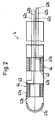
- the catheter 4 preferably also comprises at least one Ultrasonic transducer 44 for receiving and / or transmitting of ultrasonic signals because it makes it simple and Safe localization of the catheter 4 or the electrodes 41a, 41c in the heart 10 by means of ultrasound becomes. This localization will be discussed later described in detail.
- Each ultrasonic transducer 44 comprises a transducer layer 43 made of piezoelectric Material between the two electrodes 41a and 41b is embedded.
- the one shown in Fig. 2 Embodiment are the ultrasonic transducers 44 each designed in a ring and arranged so that the Include catheter 4 along its circumference.
- the electrodes 41a and 41b are shown exaggeratedly thick in FIG.
- the electrodes 41a and 41b are conductive Coatings on the surfaces of the converter layers 43.
- those of the Converter layer 43 generated electrical signals tapped and via the connecting lines 42a, 42b Control and measuring unit 5 are supplied.
- the converter layers 43 can be electrical impulses from the control and Measuring unit 5 via the connecting lines 42a, 42b and the electrodes 41a, 41b on the converter layers 43 are transmitted, for sending ultrasonic signals be stimulated.
- the electrodes 41a have a double function. she serve on the one hand for the local recording of the Activity signals from the heart 10 and form to the other part of the ultrasonic transducer 44.
- the measure, that the ultrasonic transducer 44 also as an electrode for serves local detection of electrical activity advantageous because it is a particularly space-saving and allows inexpensive design of the catheter 4.
- Ultrasonic transducer 44 Except for the annular configuration of the Ultrasonic transducer 44 is of course also z. Legs plate-shaped design possible, that is Ultrasonic transducer 44 does not encompass the entire scope the catheter 4. Furthermore, it is possible on a Catheter 4 both plate-shaped and ring-shaped Provide ultrasonic transducer 44. Of course he can Ultrasonic transducers 44 also have other shapes and / or be arranged inside the catheter.
- the ultrasonic transducer 44 and the Electrodes 41a which serve to detect the activity, can also be structurally separate from one another.
- the catheter 4 as shown in FIG. 2, for this purpose comprises a plurality of electrodes 41a, 41c, so that multiple activity signals from different local Areas of the heart 10 can be detected simultaneously.
- the Electrodes 41a, 41c can be one-dimensional, i.e. along a line, but especially also two-dimensional, d. H. on an area, or three-dimensional, for example on one Catheter, the distal end of which can be spatially stretched is arranged.
- ultrasonic transducers 44 are provided to determine the location of the catheter in space, and so that the position of the individual electrodes 41a, 41c, easier and more precise to be able to determine.
- an ultrasonic transducer 44 so that it is in relation to the catheter 4th is mobile. This makes it possible to Ultrasonic transducers 44 in different positions to move with respect to the catheter 4, thus each to determine the spatial position of the individual electrodes.
- the measuring head 22 To operate the system, first the measuring head 22 the ultrasonic device 2 near the body structure to be imaged, here of the heart 10, placed.
- the measuring head 22 is preferably used for this purpose in the Introduced esophagus because from there a achieve particularly good visual representation of the heart leaves.
- Ultrasonic echo signals are generated by ultrasonic module 21 in connection with the reconstruction unit 7 a preferably three-dimensional pictorial representation of the Heart.
- this pictorial representation approximately in real time, whereby continuously a current visualization of the heart is made possible.
- the catheter 4 is in a known manner in the Heart 10 introduced. Depending on how many electrodes 41a, 41c the catheter 4 for detecting the electrical Has activity signals, it is either on navigated different places in the heart 10 to get there successively the local activity, e.g. Belly contactless, to capture, or it will be at the same time several positions of the heart 10 the local Activities recorded.
- the activity signals are over the connecting lines 42a, 42b to the drive and Measurement unit 5 forwarded.
- the catheter 4 is preferably located in the Hearts 10 but using ultrasound.
- the Catheter 4 - as already mentioned - at least one Ultrasonic transducer 44.
- the catheter 4 is preferably located in the Hearts 10 but using ultrasound.
- the Catheter 4 - as already mentioned - at least one Ultrasonic transducer 44.
- the catheter 4 at least one Ultrasonic transducer 44.
- these apply Explanations in a similar manner also for a plurality of ultrasonic transducers 44 on the catheter 4.
- the ultrasound transducer 44 can either be for the passive or be designed for active operation. “Passive” means that the ultrasonic transducer 44 only for the Reception of ultrasound signals is used "active” means that he himself send out ultrasonic signals can.
- the measuring head 22 sends the ultrasound device 2 Ultrasonic signals, which among other things also Ultrasound transducer 44 of the catheter can hit.
- Ultrasonic transducer 44 sends this when hit by an ultrasonic wave appropriate information to the Allocation unit 6 or the ultrasound module 21.
- Da it is known at what times and in which Direction from the measuring head 22 ultrasonic waves or - impulses were sent out, how big the Ultrasound propagation speed is and when receive an ultrasonic echo signal from the measuring head 22 the time of the encounter may be one Ultrasonic wave on the ultrasonic transducer 44 in Catheter 4 a spatial position of the ultrasound transducer 44 and thus the electrodes 41a, 41c.
- the location information can also the activity signal assigned, that is, the local area of the heart 10, for the activity of which the signal is representative.
- the ultrasonic transducer 44 If the ultrasonic transducer 44 is operated actively, then it converts a received ultrasound pulse from the Measuring head 22 comes into an electrical signal and transmits this to a transponder that for example in the control and measuring unit 5 can be integrated or as a separate structural Unit is realized. The transponder then generates an Send signal and send this to the ultrasonic transducer 44, which then emits an ultrasound signal. This Ultrasonic signal is received by the measuring head 22 and on the ultrasound module 21 is forwarded. That from Ultrasonic transducer 44 emitted ultrasonic signal preferably has a special characteristic, such as for example a modulation, a special duration or Intensity to make it particularly easy from the Echo signals from the body structure to be imaged originate, is distinguishable. Thus, the Ultrasonic device 2, the spatial location of the Ultrasonic transducer 44 and thus the location of the Detect electrodes 41a, 41c. That way too can each activity signal its specific Location information can be assigned.
- the ultrasonic transducer 44 can thus both passive as well as in active mode an automatic Determination of the position of the catheter 4 in the heart 10 respectively. Because the allocation unit 6 can if necessary in connection with the Ultrasound device 2, using the signals from the ultrasound transducer (s) 44, everyone second signal, here every local activity signal, automatically assign the associated location information, the indicates for which local area of the heart 10 the respective activity signal is representative.
- each activity signal has assigned its location information
- the Activity signals along with their location information the visualization unit 8 transmits. This creates then from the geometric form, that is, from the Reconstruction unit 7 provided data for the pictorial representation, and from the activity signals with assigned location information an image of the heart 10, where the picture is both the pictorial representation as well the activity signals in each other locally assigned Way includes. This means that the electrical Activities of the heart of the three-dimensional pictorial Representation to be overlaid. In a preferred one The location of the Catheters 4 in the heart 10 included in the picture.
- the image can be displayed in different ways respectively.
- the time spread of the EKG in numbers or symbols on the respective associated location. It is also possible the temporally and spatially resolved EKG using Represent false colors by any delay time relative to a predeterminable starting time certain color is assigned. It is also possible the spread of activity as moving To represent wavefront.
- the image with the preferably three-dimensional Representation and the activity signals can be done with the help various visualization media such as one Monitor, a so-called head mounted display (HMD), or a screen - possibly in connection with a pair of 3D glasses.
- HMD head mounted display
- the preferably three-dimensional pictorial representation only be created once, and the current second Signals are always new with this visual Representation combined or incorporated into this. Also it is possible to visualize it on request or renew at definable discrete time intervals. There is also the possibility, especially with such fast ultrasound systems 2, as already in the European Patent Application No. 97811021.1 cited are disclosed, which are preferably three-dimensional pictorial representation approximately in real time, ie continuously, update. Furthermore it is possible, only parts of the image continuously or at discrete time intervals To update. For example, such parts of the pictorial representation, the areas are updated of the heart reflect that of particular interest are, e.g. B. the area in which the Catheter.
- the system according to the invention is preferably for transesophageal cardiac imaging and intracardiac ECG measurement is designed, so are quite other embodiments possible.
- the Acquisition of ultrasound signals for the visual Representation also take place from outside the body, that is, without inserting the measuring head 22 into the body.
- the measuring device 3 can also be designed in this way be that the second signals (activity signals) can grasp from outside the body, for example in the form of a surface ECG.
- the Measuring device 3 then comprises, for example, at least an electrode for local detection of the electrical Activity of the heart or organ 10, this being Electrode is attached to the body surface.
- the system or method according to the invention can be used advantageously for ablation treatments.
- Energy form for denaturing the tissue is common High frequency energy used.
- the system or method according to the invention is not based on limited examination or treatment of the heart. It is also suitable for other organs and / or others second signals, for example the determination of others Parameters related to the function of the organ related, e.g. B. pressure, temperature or chemical Parameters.
Landscapes
- Life Sciences & Earth Sciences (AREA)
- Health & Medical Sciences (AREA)
- Medical Informatics (AREA)
- Molecular Biology (AREA)
- Nuclear Medicine, Radiotherapy & Molecular Imaging (AREA)
- Pathology (AREA)
- Radiology & Medical Imaging (AREA)
- Engineering & Computer Science (AREA)
- Biomedical Technology (AREA)
- Heart & Thoracic Surgery (AREA)
- Physics & Mathematics (AREA)
- Biophysics (AREA)
- Surgery (AREA)
- Animal Behavior & Ethology (AREA)
- General Health & Medical Sciences (AREA)
- Public Health (AREA)
- Veterinary Medicine (AREA)
- Measurement And Recording Of Electrical Phenomena And Electrical Characteristics Of The Living Body (AREA)
- Ultra Sonic Daignosis Equipment (AREA)
- Surgical Instruments (AREA)
- Closed-Circuit Television Systems (AREA)
- Measurement Of Length, Angles, Or The Like Using Electric Or Magnetic Means (AREA)
Abstract
Description
Die Erfindung betrifft ein System sowie ein verfahren zur Visualisierung von Aktivitäten eines Organs. Insbesondere betrifft die Erfindung ein System und ein Verfahren zur Visualisierung der Aktivität des Herzens.The invention relates to a system and a method for Visualization of activities of an organ. Especially The invention relates to a system and a method for Visualization of the activity of the heart.
Bei der Diagnose und der Behandlung von Herzrhythmusstörungen werden heute in der Kardiologie häufig Katheter eingesetzt, die in das Herz eingeführt werden, um dort zum einen elektrophysiologische Signale zu erfassen und zum anderen gezielt Ablationen kardialen Gewebes durchzuführen, welches die Ursache der Herzrhythmusstörungen ist. Dazu ist es bekannt, mit einem Katheter an verschiedenen Positionen im Herzen mittels einer Elektrode die elektrische Aktivität des Herzens lokal zu erfassen. Der Katheter kann weiterhin spezielle Sensoren enthalten, die es erlauben, seine jeweilige Lage im Herzen zu detektieren, beispielsweise mittels spezieller elektromagnetischer Felder. Anhand der so erfassten Daten lässt sich nach und nach eine Art dreidimensionaler Darstellung der elektrischen Aktivitäten des Herzens aufbauen, die beispielsweise von einem Arzt analysiert werden kann. In the diagnosis and treatment of Cardiac arrhythmias are used today in cardiology often used catheters that are inserted into the heart be there for one electrophysiological signals to capture and on the other hand targeted cardiac ablations To perform tissue which is the cause of the Cardiac arrhythmia is. It is known to do this with a Catheters at various positions in the heart an electrode the electrical activity of the heart to be recorded locally. The catheter can also be special Contain sensors that allow its respective location to detect in the heart, for example by means of special electromagnetic fields. Based on that recorded data can gradually become a kind three-dimensional representation of the electrical Build up activities of the heart, for example by can be analyzed by a doctor.
Derart arbeitende Vorrichtungen haben Jedoch den Nachteil, dass die örtlichen Informationen relativ ungenau und lückenhaft sind, weil sie nur von solchen Positionen vorliegen, an denen sich der Katheter bereits einmal befunden hat. Weiterhin bringt die Reproduzierbarkeit einer bestimmten Katheterposition Schwierigkeiten mit sich, weil sich beispielsweise die örtlichen Gegebenheiten aufgrund des Herzschlags ändern. Zudem kann es vorkommen, dass an wichtigen Orten des Herzens keine Signale aufgenommen wurden, wodurch das räumlich aufgelöste Elektrokardiogramm (EKG) erhebliche Fehler aufweisen kann.Devices operating in this way, however, have the Disadvantage that the local information is relative are inaccurate and incomplete because they are only from such Positions are present where the catheter is already once found. Furthermore, the Reproducibility of a specific catheter position Difficulties with themselves because, for example, the change local conditions due to the heartbeat. In addition, it can happen that in important places of the Heart no signals were recorded, so that spatially resolved electrocardiogram (EKG) considerable Can have errors.
Es ist daher eine Aufgabe der Erfindung, ein System und ein Verfahren zur Visualisierung von Aktivitäten eines Organs, insbesondere des Herzens, bereitzustellen, die eine genaue und zuverlässige Visualisierung der Organaktivität ermöglichen. Insbesondere sollen es das System und das Verfahren ermöglichen, den räumlichen und zeitlichen Verlauf der Organaktivitäten in übersichtlicher Weise darzustellen.It is therefore an object of the invention, a system and a process for visualizing activities of a Organ, especially the heart, to provide the an accurate and reliable visualization of the Enable organ activity. In particular, it should System and method enable the spatial and temporal course of organ activities in to present clearly.
Die diese Aufgaben lösenden Gegenstände der Erfindung sind durch die Merkmale der unabhängigen Ansprüche der jeweiligen Kategorie gekennzeichnet.The objects of the invention achieving these objects are characterized by the features of the independent claims marked in each category.
Erfindungsgemäss wird also vorgeschlagen, mittels einer bildgebenden Ultraschallvorrichtung sowie mit einer Rekonstruktionseinheit eine bildliche Darstellung des Organs oder von Teilen des Organs zu erstellen, sowie mit einer Messvorrichtung zweite Signale zu erfassen, die repräsentativ für die Aktivität des Organs sind. Diese Messvorrichtung umfasst z. B. in einer bevorzugten Ausführungsform einen Katheter, mit dem die lokale Aktivität des Organs, beispielsweise in Form lokaler elektrokardiografischer (EKG-) Daten, die als zweite Signale dienen, an mehreren Positionen des Organs erfasst wird.According to the invention, it is therefore proposed to use a imaging ultrasound device and with a Reconstruction unit a pictorial representation of the Organs or parts of the organ to create, as well as with a measuring device to detect second signals are representative of the activity of the organ. This Measuring device includes e.g. B. in a preferred Embodiment a catheter with which the local Activity of the organ, for example in the form of local electrocardiographic (EKG) data, the second Signals serve to be recorded at several positions of the organ becomes.
Erfindungsgemäss ordnet eine Zuordnungseinheit den zweiten Signalen jeweils als Ortsinformation den örtlichen Bereich des Organs zu, für dessen Aktivität das jeweilige zweite Signal repräsentativ ist. Schliesslich werden in einer Visualisierungseinheit die bildliche Darstellung, die zweiten Signalen sowie die jeweils zugehörigen Ortsinformationen zu einem Bild kombiniert, das sowohl die bildliche Darstellung als auch die Aktivität des Organs in einander örtlich zugeordneter Weise umfasst.According to the invention, an assignment unit assigns the second signals each as location information local area of the organ for whose activity the each second signal is representative. Finally are the visual in a visualization unit Representation, the second signals as well as each associated location information combined into an image, that both the visual representation and the Activity of the organ in each other Way includes.
Die Ultraschallvorrichtung dient folglich dazu, eine bildliche bzw. geometrische Darstellung des Organs zu erzeugen, die mit den lokal aufgelösten zweiten Signalen, also den Aktivitätssignalen, derart kombiniert oder überlagert wird, dass sich ein Bild ergibt, welches die geometrische bildliche Darstellung des Organs zeigt und zusätzlich die lokale Aktivität des Organs als Funktion des Orts.The ultrasound device thus serves to pictorial or geometric representation of the organ generate that with the locally resolved second signals, so the activity signals, combined in such a way or is superimposed that there is an image which shows the geometric pictorial representation of the organ shows and additionally the local activity of the organ as a function of the place.
Da die geometrische bildliche Darstellung des Organs primär nicht auf Ortsinformationen beruht, die von der Messvorrichtung für die zweiten Signale kommen, sondern im wesentlichen unabhängig von dieser Messvorrichtung mittels einer bildgebenden Ultraschallvorrichtung erstellt wird, ermöglicht das erfindungsgemässe System bzw. Verfahren eine deutlich genauere, örtlich höher aufgelöste und vollständigere bildliche Darstellung des Organs, in welche dann in der Folge die Aktivitätssignale eingearbeitet werden können. Hierdurch lässt sich eine sehr übersichtliche, zuverlässige und örtlich aufgelöste Visualisierung der Organaktivität realisieren. Because the geometric pictorial representation of the organ primarily not based on location information provided by the Measuring device for the second signals come, but essentially independent of this measuring device by means of an ultrasound imaging device is created, the system according to the invention enables or procedure a significantly more accurate, locally higher resolved and more complete pictorial representation of the Organs, in which the activity signals can be incorporated. This allows one very clear, reliable and locally resolved Realize visualization of organ activity.
Bei dem erfindungsgemässen Verfahren zur Visualisierung von Aktivitäten eines Organs, insbesondere des Herzens, wird mittels Ultraschallmesssignalen eine bildliche Darstellung des Organs oder von Teilen des Organs, insbesondere eine dreidimensionale bildliche Darstellung, erzeugt. Ferner werden zweite Signale, insbesondere elektrischer Signale, welche repräsentativ für die Aktivität des Organs sind, mit der genannten bildlichen Darstellung zu einem Bild des Organs oder von Teilen des Organs kombiniert, wobei das Bild sowohl die bildliche Darstellung als auch die Aktivität des Organs in einander örtlich zugeordneter Weise umfasst.In the visualization method according to the invention activities of an organ, especially the heart, becomes a visual by means of ultrasonic measurement signals Representation of the organ or parts of the organ, especially a three-dimensional visual representation, generated. Furthermore, second signals, in particular electrical signals which are representative of the Activity of the organ are, with the said pictorial Representation to an image of the organ or parts of the Organ combined, the image being both the pictorial Representation as well as the activity of the organ in each other includes locally assigned manner.
Vorteilhafterweise wird das Bild kontinuierlich oder in diskreten Zeitabständen aktualisiert, indem aktuelle zweite Signale mit der bildlichen Darstellung neu kombiniert werden. Durch diese Massnahme ist neben der räumlichen Information bezüglich der Aktivität auch der zeitliche Verlauf der Aktivität als Funktion des Orts darstellbar.The image is advantageously continuous or in discrete time intervals updated by current second signals with the visual representation new be combined. Through this measure, in addition to the spatial information regarding the activity of the temporal course of the activity as a function of the location representable.
Weitere vorteilhafte Massnahmen und bevorzugte Ausgestaltungen der Erfindungsgegenstände ergeben sich aus den abhängigen Ansprüchen.Other advantageous measures and preferred Refinements of the subject matter of the invention result from the dependent claims.
Im folgenden wird die Erfindung sowohl in Bezug auf die verfahrenstechnischen als auch in Bezug auf die apparativen Aspekte anhand der Zeichnung und anhand von Ausführungsbeispielen näher erläutert. In der schematischen nicht massstäblichen Zeichnung zeigen:
- Fig. 1:
- eine symbolische Darstellung eines Ausführungsbeispiels des erfindungsgemässen Systems, und
- Fig. 2:
- eine schematische Schnittdarstellung eines Katheters einer Messvorrichtung des erfindungsgemässen Systems.
- Fig. 1:
- a symbolic representation of an embodiment of the system according to the invention, and
- Fig. 2:
- is a schematic sectional view of a catheter of a measuring device of the system according to the invention.
Fig. 1 zeigt in einer symbolischen Darstellung die
wesentlichen Komponenten eines Ausführungsbeispiels des
erfindungsgemässen Systems, das gesamthaft mit dem
Bezugszeichen 1 bezeichnet ist. Das erfindungsgemässe
System 1 zur Visualisierung von Aktivitäten eines Organs
10 umfasst eine bildgebenden Ultraschallvorrichtung 2 zum
Bereitstellen von ersten Signalen, eine
Rekonstruktionseinheit 7, welche aus den ersten Signalen
eine bildliche Darstellung des Organs 10 oder von Teilen
des Organs 10 erstellt, eine Messvorrichtung 3 zum
örtlich aufgelösten Erfassen zweiter Signale, welche
repräsentativ für die Aktivität des Organs 10 sind, sowie
eine Zuordnungseinheit 6, welche den zweiten Signalen
jeweils als Ortsinformation den örtlichen Bereich des
Organs 10 zuordnet, für dessen Aktivität das jeweilige
zweite Signal repräsentativ ist. Das System 1 umfasst
ferner eine Visualisierungseinheit 8, welche aus der
bildlichen Darstellung, den zweiten Signalen sowie der
jeweils zugehörigen Ortsinformation ein Bild des Organs
10 oder von Teilen des Organs 10 erzeugt, wobei das Bild
sowohl die bildliche Darstellung als auch die Aktivität
des Organs 10 in einander örtlich zugeordneter Weise
umfasst.Fig. 1 shows the symbolic representation
essential components of an embodiment of the
system according to the invention, the whole with the
Im folgenden wird mit beispielshaftem Charakter auf den
für die Praxis wichtigen Fall Bezug genommen, dass das
Organ 10, dessen Aktivität visualisiert werden soll, das
Herz ist, und dass die zweiten Signale, welche
repräsentativ für die Aktivität des Organs sind,
elektrische Aktivitätssignale (EKG-Signale) des Herzens
10 sind, welche mittels eines Katheters 4 intrakardial
erfasst werden. The following is an example of the
important case in practice that the
Die bildgebende Ultraschallvorrichtung 2 umfasst einen
Messkopf 22 zum Aussenden von Ultraschallsignalen und zum
Empfangen der von der abzubildenden Körperstruktur
reflektierten Echosignale. Der Messkopf 22 wird von einem
Ultraschallmodul 21 angesteuert. Der Messkopf 22
übermittelt die empfangenen Echosignale an das
Ultraschallmodul 21, welches diese Echosignale
vorverarbeitet, z. B. verstärkt und/oder filtert, und sie
anschliessend als erste Signale an die
Rekonstruktionseinheit 7 weiterleitet. Die
Rekonstruktionseinheit 7 wandelt die ersten Signale
mittels an sich bekannter Prozeduren zur zwei- bzw.
dreidimensionalen Bildgebung in ein Format um, welches
eine bildliche Darstellung des Organs 10 ermöglicht.The
Vorzugsweise sind die Ultraschallvorrichtung 2 und die
Rekonstruktionseinheit 7 derart ausgestaltet, dass sie
eine dreidimensionale (3D-) bildliche Darstellung des
Organs 10 oder von Teilen des Organs ermöglichen. Mit
"dreidimensionaler" Darstellung ist dabei gemeint, dass
die Darstellung tatsächlich dreidimensional ist oder,
dass sie zwar eben ist aber einen dreidimensionalen
Eindruck vermittelt, z. B. mittels Methoden der
räumlichen oder perspektivischen Darstellung oder der
Projektion.Preferably, the
In der europäischen Patentanmeldung Nr. 97811021.1 wird eine Ultraschallvorrichtung offenbart, die sich dadurch auszeichnet, dass sie in extrem kurzer Zeit - nämlich näherungsweise in Echtzeit - dreidimensionale bildliche Darstellungen des Herzens ermöglicht. Die dreidimensionale Abbildung des Herzens mittels Ultraschall erfolgt dabei vorzugsweise transösophagal. Aufgrund der dadurch geschaffenen Möglichkeit, das Herz nahezu kontinuierlich mittels stets aktueller dreidimensionaler Darstellungen abzubilden, ist ein solches Ultraschallsystem, auch im Hinblick auf die Navigation und die Lokalisierung von Instrumenten im Herzen, für das erfindungsgemässe System bzw. Verfahren besonders gut geeignet. Bezüglich der detaillierten Beschreibung der Ausgestaltung einer solchen schnellen bildgebenden 3D-Ultraschallvorrichtung wird auf die europäische Patentanmeldung Nr. 97811021.1 verwiesen.In European patent application No. 97811021.1 discloses an ultrasound device that distinguishes itself distinguishes itself in an extremely short time - namely approximately in real time - three-dimensional pictorial Representations of the heart enabled. The three-dimensional image of the heart by means of Ultrasound is preferably transesophageal. Because of the opportunity this creates, the heart almost continuously with the most up-to-date Mapping three-dimensional representations is a such ultrasound system, also with regard to Navigation and localization of instruments in the Hearts, for the system or method according to the invention particularly well suited. Regarding the detailed Description of the design of such a quick 3D imaging ultrasound device is placed on the European patent application No. 97811021.1.
Es versteht sich, dass ausser diesen bevorzugten Ultraschallvorrichtungen auch alle anderen an sich bekannten bildgebenden Ultraschallgeräte für das erfindungsgemässe System bzw. Verfahren eingesetzt werden können. Dabei ist es nicht notwendig, dass das Ultraschallgerät für die dreidimensionale Bildgebung ausgelegt sein muss. Das erfindungsgemässe System bzw. Verfahren lässt sich durchaus auch mit solchen Ultraschallgeräten betreiben, die für zweidimensionale Ultraschalldarstellungen ausgestaltet sind.It is understood that besides these preferred Ultrasound devices also everyone else per se known imaging ultrasound devices for the system or method according to the invention are used can. It is not necessary that that Ultrasound machine for three-dimensional imaging must be designed. The system or Procedures can also be done with such Operate ultrasound equipment for two-dimensional Ultrasound representations are designed.
Die Zuordnungseinheit 6 kann auch in die
Ultraschallvorrichtung 2 integriert sein. Ferner können
die Rekonstruktionseinheit 7 und/oder das
Ultraschallmodul 21 und/oder die Visualisierungseinheit 8
und/oder die Zuordnungseinheit 6 eine bauliche Einheit
bilden, die Teil der Ultraschallvorrichtung 2 ist.The
Die Messvorrichtung 3 zum Erfassen der zweiten Signale,
hier beispielsweise der elektrischen Aktivitätssignale
des Herzens 10, umfasst in dem Ausführungsbeispiel den
Katheter 4, der zur lokalen Erfassung der
Aktivitätssignale in das Herz eingeführt wird, sowie eine
Ansteuer- und Messeinheit 5, welche die von dem Katheter
kommenden Signale empfängt. Der Katheter 4 ist mit Hilfe
an sich bekannter Mittel im Innern des Herzens
navigierbar. Zum besseren Verständnis zeigt Fig. 2 eine
mögliche Ausgestaltung des Katheters 4 in einer
schematischen Schnittdarstellung. Er umfasst mindestens
eine Elektrode 41a, 41c zur lokalen Erfassung der
elektrischen Aktivitätssignale des Herzens 10. In Fig. 2
sind mit beispielhaftem Charakter drei Elektroden 41a,41c
zur Erfassung der Aktivitätssignale dargestellt, wobei
zwei ringförmige Elektroden 41a an der Mantelfläche des
Katheters 4 angeordnet sind und eine Elektrode 41c am
distalen Ende des Katheters 4. Die Elektroden 41a, 41c
können als Kontakt-Elektroden oder für die kontaktlose
Erfassung der Aktivitätssignale ausgestaltet sein. Die
Elektroden 41a, 41c sind über Verbindungsleitungen
42a,42c mit der Ansteuer- und Messeineinheit 5 verbunden,
um die von ihnen erfassten Aktivitätssignale an die
Ansteuer- und Auswerteeinheit 5 zu übermitteln. Die
Erfassung der Aktivitätssignale mittels der Elektroden
41a, 41c kann sowohl unipolar als auch bipolar erfolgen.The measuring device 3 for detecting the second signals,
here for example the electrical activity signals
of the
Vorzugsweise umfasst der Katheter 4 auch mindestens einen
Ultraschallwandler 44 zum Empfangen und/oder Aussenden
von Ultraschallsignalen, weil dadurch eine einfache und
sichere Lokalisierung des Katheters 4 bzw. der Elektroden
41a, 41c im Herzen 10 mittels Ultraschall ermöglicht
wird. Diese Lokalisierung wird weiter hinten noch
detailliert beschrieben. Jeder Ultraschallwandler 44
umfasst eine Wandlerschicht 43 aus piezoelektrischem
Material, die zwischen den beiden Elektroden 41a und 41b
eingebettet ist. Bei der in Fig. 2 dargestellten
Ausführungsform sind die Ultraschallwandler 44 jeweils
ringförmig ausgestaltet und so angeordnet, dass sie den
Katheter 4 entlang seines Umfangs umfassen. Die Elektoden
41a und 41b sind in Fig. 2 übertrieben dick dargestellt;
üblicherweise sind die Elektroden 41a und 41b leitfähige
Beschichtungen auf den Oberflächen der Wandlerschichten
43. Mittels der Elektoden 41a, 41b können die von der
Wandlerschicht 43 erzeugten elektrischen Signale
abgegriffen und über die Verbindungsleitungen 42a,42b der
Ansteuer- und Messeinheit 5 zugeführt werden. In
umgekehrter Weise können die Wandlerschichten 43 mittels
elektrischer Impulse, die von der Ansteuer- und
Messeinheit 5 über die Verbindungsleitungen 42a, 42b und
die Elektroden 41a,41b auf die Wandlerschichten 43
übertragen werden, zum Aussenden von Ultraschallsignalen
angeregt werden.The
Wie dies die voranstehende Beschreibung schon andeutet,
kommt den Elektroden 41a eine doppelte Funktion zu. Sie
dienen zum einen der lokalen Erfassung der
Aktivitätssignale des Herzens 10 und bilden zum anderen
einen Teil des Ultraschallwandlers 44. Die Massnahme,
dass der Ultraschallwandler 44 auch als Elektrode zum
lokalen Erfassen der elektrischen Aktivität dient, ist
vorteilhaft, weil sie eine besonders platzsparende und
kostengünstige Ausgestaltung des Katheters 4 ermöglicht.As the previous description suggests,
the
Ausser der ringförmigen Ausgestaltung des
Ultraschallwandlers 44 ist natürlich auch z. B. eine
plattenförmige Ausgestaltung möglich, das heisst der
Ultraschallwandler 44 umfasst nicht den gesamten Umfang
des Katheters 4. Ferner ist es möglich, auf einem
Katheter 4 sowohl plattenförmige als auch ringförmige
Ultraschallwandler 44 vorzusehen. Natürlich kann der
Ultraschallwandler 44 auch andere Formen aufweisen
und/oder im Innern des Katheters angeordnet sein.Except for the annular configuration of the
Es versteht sich, dass der Ultraschallwandler 44 und die
Elektroden 41a, die zum Erfassen der Aktivität dienen,
auch baulich voneinander getrennt sein können.It is understood that the
Im Hinblick auf eine möglichst effiziente und rasche
Erfassung der lokalen Aktivitätssignale ist es
vorteilhaft, wenn der Katheter 4, wie in Fig. 2 gezeigt,
hierfür mehrere Elektroden 41a,41c umfasst, sodass
mehrere Aktivitätssignale von unterschiedlichen lokalen
Bereichen des Herzens 10 gleichzeitig erfassbar sind. Die
Elektroden 41a, 41c können dabei eindimensional, d.h.
entlang einer Linie, aber insbesondere auch
zweidimensional, d. h. auf einer Fläche, oder
dreidimensional, beispielsweise auf einem solchen
Katheter, dessen distaler Endbereich räumlich aufspannbar
ist, angeordnet sein. Auch ist es möglich, die
leitfähige, als Elektrode 41a des Ultraschallwandlers 44
dienende Beschichtung der Wandlerschicht 43 in mehrere
elektrisch gegeneinander isolierte Teilbereiche
aufzuteilen, sodass durch eine solche leitfähige
Beschichtung mehrere Elektroden zur Erfassung der
AXtivitätssignale realisiert werden.With a view to being as efficient and quick as possible
It is detection of local activity signals
advantageous if the
Insbesondere bei mehreren Elektroden 41a,41c ist es
vorteilhaft, wenn auch mehrere Ultraschallwandler 44
vorgesehen sind, um die Lage des Katheters im Raum, und
damit die Lage der einzelnen Elektroden 41a, 41c,
einfacher und genauer feststellen zu können. Alternativ
oder ergänzend ist es möglich, einen Ultraschallwandler
44 so anzuordnen, dass er bezüglich des Katheters 4
beweglich ist. Dadurch ist es möglich, den
Ultraschallwandler 44 an verschiedene Positionen
bezüglich des Katheters 4 zu bewegen, um somit jeweils
die räumliche Lage der einzelnen Elektroden zu ermitteln.It is in particular in the case of a plurality of
Zum Betreiben des Systems wird zunächst der Messkopf 22
der Ultraschallvorrichtung 2 in der Nähe der
abzubildenden Körperstruktur, hier also des Herzens 10,
plaziert. Vorzugsweise wird der Messkopf 22 dazu in den
Ösophagus eingeführt, weil sich von dort aus eine
besonders gute bildliche Darstellung des Herzens erzielen
lässt. Mittels der vom Messkopf 22 empfangenen
Ultraschallechosignale erstellt das Ultraschallmodul 21
in Verbindung mit der Rekonstruktionseinheit 7 eine
vorzugsweise dreidimensionale bildliche Darstellung des
Herzens. Bei der Verwendung solcher schnellen
bildgebenden Ultraschallvorrichtungen 2 wie sie in der
bereits zitierten europäischen Patentanmeldung 97811021.1
offenbart sind, kann diese bildliche Darstellung
näherungsweise in Echtzeit erfolgen, wodurch
kontinuierlich eine aktuelle Visualisierung des Herzens
ermöglicht wird.To operate the system, first the measuring
Der Katheter 4 wird in an sich bekannter Weise in das
Herz 10 eingeführt. Je nachdem, wie viele Elektroden
41a,41c der Katheter 4 zur Erfassung der elektrischen
Aktivitätssignale aufweist, wird er entweder an
verschiedene Stellen im Herzen 10 navigiert, um dort
sukzessive jeweils die lokale Aktivität, z. B. auch
kontaktlos, zu erfassen, oder es werden gleichzeitig an
mehreren Positionen des Herzens 10 die lokalen
Aktivitäten erfasst. Die Aktivitätssignale werden über
die Verbindungsleitungen 42a, 42b an die Ansteuer- und
Messeinheit 5 weitergeleitet.The
Bei einer dreidimensionalen bildlichen Darstellung des
Herzens 10 in Echtzeit lässt sich die aktuelle Lage
und/oder Position des Katheters 4 im Herzen 10
prinzipiell auch ohne zusätzliche Hilfsmittel in der 3D-Darstellung
erkennen. Somit kann beispielsweise das
Bedienpersonal den erfassten Aktivitätssignalen jeweils
die Ortsinformation, das heisst den örtlichen Bereich des
Herzens 10, für den das jeweils erfasste Aktivitätssignal
repräsentativ ist, manuell zuordnen, indem die aktuelle
Lage des Katheters 4 in die Zuordnungseinheit 6
eingegeben wird.In a three-dimensional visual representation of the
Vorzugsweise erfolgt die Lokalisierung des Katheters 4 im
Herzen 10 aber mittels Ultraschall. Hierfür umfasst der
Katheter 4 - wie bereits erwähnt - mindestens einen
Ultraschallwandler 44. Bei der folgenden Beschreibung
wird der Einfachheit halber und, weil es zum Verständnis
ausreicht, angenommen, dass nur ein Ultraschallwandler 44
am Katheter 4 vorgesehen ist. Natürlich gelten diese
Erläuterungen in sinngemäss gleicher Weise auch für
mehrere Ultraschallwandler 44 auf dem Katheter 4.The
Der Ultraschallwandler 44 kann entweder für den passiven
oder für den aktiven Betrieb ausgestaltet sein. "Passiv"
bedeutet, dass der Ultraschallwandler 44 nur für den
Empfang von Ultraschallsignalen verwendet wird, "aktiv"
bedeutet, dass er selbst Ultraschallsignale aussenden
kann.The
Zum Erzeugen der dreidimensionalen bildlichen Darstellung
sendet der Messkopf 22 der Ultraschallvorrichtung 2
Ultraschallsignale aus, die unter anderem auch den
Ultraschallwandler 44 des Katheters treffen können. Beim
passiven Betrieb des Ultraschallwandlers 44 sendet
dieser, wenn er von einer Ultraschallwelle getroffen
wird, eine entsprechende Information an die
Zuordnungseinheit 6 oder das Ultraschallmodul 21. Da
bekannt ist, zu welchen Zeitpunkten und in welche
Richtung von dem Messkopf 22 Ultraschallwellen oder -
impulse ausgesendet wurden, wie gross die
Ausbreitungsgeschwindigkeit des Ultraschalls ist und wann
ein Ultraschallechosignal vom Messkopf 22 empfangen
wurde, kann der Zeitpunkt des Auftreffens einer
Ultraschallwelle auf den Ultraschallwandler 44 im
Katheter 4 einer räumlichen Lage des Ultraschallwandlers
44 und damit der Elektroden 41a, 41c zugeordnet werden.
Somit kann auch dem Aktivitätssignal die Ortsinformation
zugeordnet werden, das heisst, derjenige örtliche Bereich
des Herzens 10, für dessen Aktivität das Signal
repräsentativ ist. To create the three-dimensional image
the measuring
Wird der Ultraschallwandler 44 aktiv betrieben, so
wandelt er einen empfangenen Ultraschallimpuls, der vom
Messkopf 22 kommt, in ein elektrisches Signal um und
übermittelt dieses an einen Transponder, der
beispielsweise in der Ansteuer- und Messeinheit 5
integriert sein kann oder als eine eigene bauliche
Einheit realisiert ist. Der Transponder erzeugt dann ein
Sendesignal und schickt dieses an den Ultraschallwandler
44, der daraufhin ein Ultraschallsignal aussendet. Dieses
Ultraschallsignal wird vom Messkopf 22 empfangen und an
das Ultraschallmodul 21 weitergeleitet. Das vom
Ultraschallwandler 44 ausgesendete Ultraschallsignal
weist bevorzugt eine besondere Charakteristik auf, wie
beispielsweise eine Modulation, eine besondere Dauer oder
Intensität, damit es besonders einfach von den
Echosignalen, die von der abzubildenden Körperstruktur
stammen, unterscheidbar ist. Somit kann die
Ultraschallvorrichtung 2 die räumliche Lage des
Ultraschallwandlers 44 und damit auch die Lage der
Elektroden 41a, 41c feststellen. Auch auf diese Weise
kann jedem Aktivitätssignal seine spezifische
Ortsinformation zugeordnet werden.If the
Mittels des Ultraschallwandlers 44 kann somit sowohl im
passiven als auch im aktiven Betrieb eine automatische
Ermittlung der Lage des Katheters 4 im Herzen 10
erfolgen. Denn die Zuordnungseinheit 6 kann,
gegebenenfalls in Verbindung mit der
Ultraschallvorrichtung 2, mit Hilfe der Signale, die von
dem oder den Ultraschallwandler(n) 44 kommen, jedem
zweiten Signal, hier also jedem lokalen Aktivitätssignal,
automatisch die zugehörige Ortsinformation zuordnen, die
angibt, für welchen lokalen Bereich des Herzens 10 das
jeweilige Aktivitätssignal repräsentativ ist. By means of the
Insbesondere bei mehreren Elektroden 41a, 41c ist es
vorteilhaft, auch mehrere Ultraschallwandler 44 am oder
im Katheter 4 vorzusehen, um dessen räumliche Lage und
Orientierung im Herzen 10 zu detektieren. Dadurch wird
nämlich eine besonders einfache und sichere automatische
Verbindung zwischen der Geometrie des Herzens 10 und den
elektrischen Aktivitätssignalen ermöglicht.It is in particular with a plurality of
Nachdem die Zuordnungseinheit 6 jedem Aktivitätssignal
seine Ortsinformation zugeordnet hat, werden die
Aktivitätssignale zusammen mit ihrer Ortsinformation an
die Visualisierungseinheit 8 übermittelt. Diese erzeugt
dann aus der geometrischen Form, das heisst, den von der
Rekonstruktionseinheit 7 gelieferten Daten für die
bildliche Darstellung, und aus den Aktivitätssignalen mit
zugeordneter Ortsinformation ein Bild des Herzens 10,
wobei das Bild sowohl die bildliche Darstellung als auch
die Aktivitätssignale in einander örtlich zugeordneter
Weise umfasst. Dies bedeutet, dass die elektrischen
Aktivitäten des Herzens der dreidimensionalen bildlichen
Darstellung überlagert werden. Bei einer bevorzugten
Variante ist zusätzlich auch die örtliche Lage des
Katheters 4 im Herzen 10 in dem Bild enthalten.After the
Die Darstellung des Bilds kann auf verschiedene Weisen erfolgen. Beispielsweise kann die zeitliche Ausbreitung des EKGs in Zahlen oder Symbolen an dem jeweils zugehörigen Ort dargestellt werden. Auch ist es möglich, das zeitlich und räumlich aufgelöste EKG mittels Falschfarben darzustellen, indem jeder Verzögerungszeit relativ zu einem vorgebbaren Anfangszeitpunkt eine bestimmte Farbe zugeordnet wird. Ferner ist es möglich, die Ausbreitung der Aktivität als sich bewegende Wellenfront darzustellen. The image can be displayed in different ways respectively. For example, the time spread of the EKG in numbers or symbols on the respective associated location. It is also possible the temporally and spatially resolved EKG using Represent false colors by any delay time relative to a predeterminable starting time certain color is assigned. It is also possible the spread of activity as moving To represent wavefront.
Das Bild mit der vorzugsweise dreidimensionalen Darstellung und den Aktivitätssignalen kann mit Hilfe verschiedener Visualisierungmedien wie zum Beispiel einem Monitor, einem sogenannten Head Mounted Display (HMD), oder einem Bildschirm - gegebenenfalls in Verbindung mit einer 3D-Brille - erfolgen.The image with the preferably three-dimensional Representation and the activity signals can be done with the help various visualization media such as one Monitor, a so-called head mounted display (HMD), or a screen - possibly in connection with a pair of 3D glasses.
Bezüglich der Aktualisierung des Bilds, entweder
kontinuierlich oder in diskreten Zeitabständen, sind
mehrere Varianten möglich. Beispielsweise kann die
vorzugsweise dreidimensionale bildliche Darstellung nur
einmal erstellt werden, und die jeweils aktuellen zweiten
Signale werden immer wieder neu mit dieser bildlichen
Darstellung kombiniert bzw. in diese eingearbeitet. Auch
ist es möglich die bildliche Darstellung auf Anforderung
oder in bestimmbaren diskreten Zeitabständen zu erneuern.
Ferner besteht die Möglichkeit, insbesondere bei solchen
schnellen Ultraschallsystemen 2, wie sie in der bereits
zitierten europäischen Patentanmeldung Nr. 97811021.1
offenbart sind, die vorzugsweise dreidimensionale
bildliche Darstellung näherungsweise in Echtzeit, also
kontinuierlich, zu aktualisieren. Weiterhin ist es auch
möglich, nur Teile der bildlichen Darstellung
kontinuierlich oder in diskreten Zeitabständen zu
aktualisieren. Beispielsweise können solche Teile der
bildlichen Darstellung aktualisiert werden, die Bereiche
des Herzens wiedergeben, die von besonderem Interesse
sind, z. B. der Bereich, in dem sich momentan der
Katheter befindet.Regarding updating the image, either
are continuous or at discrete time intervals
several variants possible. For example, the
preferably three-dimensional pictorial representation only
be created once, and the current second
Signals are always new with this visual
Representation combined or incorporated into this. Also
it is possible to visualize it on request
or renew at definable discrete time intervals.
There is also the possibility, especially with such
Auch wenn das erfindungsgemässe System vorzugsweise für
die transösophagale Herzabbildung und die intrakardiale
EKG-Messung ausgestaltet ist, so sind durchaus auch
andere Ausführungsformen möglich. Beispielsweise kann die
Erfassung der Ultraschallsignale für die bildliche
Darstellung auch von ausserhalb des Körpers erfolgen,
also ohne den Messkopf 22 in den Körper einzuführen.
Ferner kann die Messvorrichtung 3 auch so ausgestaltet
sein, dass sie die zweiten Signale (Aktivitätssignale)
von ausserhalb des Körpers aus erfassen kann,
beispielsweise in Form eines Oberflächen-EKGs. Die
Messvorrichtung 3 umfasst dann beispielsweise mindestens
eine Elektrode zum lokalen Erfassen der elektrischen
Aktivität des Herzens oder Organs 10, wobei diese
Elektrode auf der Körperoberfläche angebracht wird.Even if the system according to the invention is preferably for
transesophageal cardiac imaging and intracardiac
ECG measurement is designed, so are quite
other embodiments possible. For example, the
Acquisition of ultrasound signals for the visual
Representation also take place from outside the body,
that is, without inserting the measuring
Neben der elektrophysiologischen Untersuchung des Herzens
10 ist das erfindungsgemässe System bzw. Verfahren auch
vorteilhaft für Ablationsbehandlungen einsetzbar. Als
Energieform zur Denaturierung des Gewebes wird häufig
Hochfrequenz-Energie eingesetzt. Bei der vorne
beschriebenen Ausgestaltung des erfindungsgemässen
Systems können für solche Behandlungen die Elektroden
41a, 41c des Katheters 4 oder eine dieser Elektroden 41a,
41c auch als Hochfrequenz-Energiequelle für die Ablation
ausgestaltet sein. Somit ist neben der Diagnose auch die
Behandlung insbesondere von Herzrhythmusstörungen,
möglich. Es versteht sich, dass bei derartigen
Ausgestaltungen entsprechende Steuer- und
Versorgungseinrichtungen für die Hochfrequenz vorgesehen
sind. Insbesondere auch bei Ablationsbehandlungen ist die
schnelle Ultraschallvorrichtung, die eine
dreidimensionale Bildgebung des Herzens einschliesslich
des Katheters näherungsweise in Echtzeit ermöglicht,
besonders vorteilhaft, weil hierdurch eine sichere und
einfache Lokalisierung und Navigierung des Katheters 4 im
Herz 10 und gegebenenfalls die Beobachtung der
Läsionsbildung ermöglicht wird.In addition to the electrophysiological examination of the
Das erfindungsgemässe System bzw. Verfahren ist nicht auf die Untersuchung oder Behandlung des Herzens beschränkt. Es eignet sich auch für andere Organe und/oder andere zweite Signale, die beispielsweise die Bestimmung anderer Parameter, welche mit der Funktion des Organs zusammenhängen, z. B. Druck, Temperatur oder chemische Parameter, ermöglichen.The system or method according to the invention is not based on limited examination or treatment of the heart. It is also suitable for other organs and / or others second signals, for example the determination of others Parameters related to the function of the organ related, e.g. B. pressure, temperature or chemical Parameters.
Claims (15)
Priority Applications (2)
| Application Number | Priority Date | Filing Date | Title |
|---|---|---|---|
| EP98810261A EP0945104A1 (en) | 1998-03-25 | 1998-03-25 | System and method for visualising the activity of an organ |
| JP11036916A JP2000000242A (en) | 1998-03-25 | 1999-02-16 | System and method for visual display of organ activity |
Applications Claiming Priority (1)
| Application Number | Priority Date | Filing Date | Title |
|---|---|---|---|
| EP98810261A EP0945104A1 (en) | 1998-03-25 | 1998-03-25 | System and method for visualising the activity of an organ |
Publications (1)
| Publication Number | Publication Date |
|---|---|
| EP0945104A1 true EP0945104A1 (en) | 1999-09-29 |
Family
ID=8236012
Family Applications (1)
| Application Number | Title | Priority Date | Filing Date |
|---|---|---|---|
| EP98810261A Withdrawn EP0945104A1 (en) | 1998-03-25 | 1998-03-25 | System and method for visualising the activity of an organ |
Country Status (2)
| Country | Link |
|---|---|
| EP (1) | EP0945104A1 (en) |
| JP (1) | JP2000000242A (en) |
Cited By (4)
| Publication number | Priority date | Publication date | Assignee | Title |
|---|---|---|---|---|
| US6716166B2 (en) | 2000-08-18 | 2004-04-06 | Biosense, Inc. | Three-dimensional reconstruction using ultrasound |
| US6773402B2 (en) | 2001-07-10 | 2004-08-10 | Biosense, Inc. | Location sensing with real-time ultrasound imaging |
| WO2005027766A1 (en) * | 2003-09-01 | 2005-03-31 | Siemens Aktiengesellschaft | Method and device for visually assisting the electrophysiological use of a catheter in the heart |
| WO2005027765A1 (en) * | 2003-09-01 | 2005-03-31 | Siemens Aktiengesellschaft | Method and device for visually supporting an electrophysiology catheter application in the heart |
Families Citing this family (14)
| Publication number | Priority date | Publication date | Assignee | Title |
|---|---|---|---|---|
| US6556695B1 (en) * | 1999-02-05 | 2003-04-29 | Mayo Foundation For Medical Education And Research | Method for producing high resolution real-time images, of structure and function during medical procedures |
| US20070106147A1 (en) * | 2005-11-01 | 2007-05-10 | Altmann Andres C | Controlling direction of ultrasound imaging catheter |
| US8945117B2 (en) | 2009-02-11 | 2015-02-03 | Boston Scientific Scimed, Inc. | Insulated ablation catheter devices and methods of use |
| EP3391845B1 (en) | 2009-06-30 | 2020-02-12 | Boston Scientific Scimed, Inc. | Map and ablate open irrigated hybrid catheter |
| US9089340B2 (en) | 2010-12-30 | 2015-07-28 | Boston Scientific Scimed, Inc. | Ultrasound guided tissue ablation |
| US9241687B2 (en) | 2011-06-01 | 2016-01-26 | Boston Scientific Scimed Inc. | Ablation probe with ultrasonic imaging capabilities |
| CA2847846A1 (en) | 2011-09-14 | 2013-03-21 | Boston Scientific Scimed, Inc. | Ablation device with multiple ablation modes |
| CN103917185A (en) | 2011-09-14 | 2014-07-09 | 波士顿科学西美德公司 | Ablation device with ionically conductive balloon |
| CN104125811B (en) | 2011-12-28 | 2016-10-26 | 波士顿科学医学有限公司 | There is the excision probe of ultrasonic imaging capability |
| US8876817B2 (en) | 2012-01-10 | 2014-11-04 | Boston Scientific Scimed Inc. | Electrophysiology system and methods |
| WO2013115941A1 (en) | 2012-01-31 | 2013-08-08 | Boston Scientific Scimed, Inc. | Ablation probe with fluid-based acoustic coupling for ultrasonic tissue imaging |
| US10524684B2 (en) | 2014-10-13 | 2020-01-07 | Boston Scientific Scimed Inc | Tissue diagnosis and treatment using mini-electrodes |
| EP3209234B1 (en) | 2014-10-24 | 2023-11-29 | Boston Scientific Scimed Inc. | Medical devices with a flexible electrode assembly coupled to an ablation tip |
| WO2016100917A1 (en) | 2014-12-18 | 2016-06-23 | Boston Scientific Scimed Inc. | Real-time morphology analysis for lesion assessment |
Citations (5)
| Publication number | Priority date | Publication date | Assignee | Title |
|---|---|---|---|---|
| US4821731A (en) * | 1986-04-25 | 1989-04-18 | Intra-Sonix, Inc. | Acoustic image system and method |
| US4936281A (en) * | 1989-04-13 | 1990-06-26 | Everest Medical Corporation | Ultrasonically enhanced RF ablation catheter |
| EP0381816A2 (en) * | 1989-02-06 | 1990-08-16 | Arzco Medical Electronics, Inc. | Multiple electrode affixable sheet |
| WO1990013259A1 (en) * | 1989-05-03 | 1990-11-15 | Tomtec Tomographic Technologies Gmbh | Device for transoesophagal echocardiography |
| US5159931A (en) * | 1988-11-25 | 1992-11-03 | Riccardo Pini | Apparatus for obtaining a three-dimensional reconstruction of anatomic structures through the acquisition of echographic images |
-
1998
- 1998-03-25 EP EP98810261A patent/EP0945104A1/en not_active Withdrawn
-
1999
- 1999-02-16 JP JP11036916A patent/JP2000000242A/en active Pending
Patent Citations (5)
| Publication number | Priority date | Publication date | Assignee | Title |
|---|---|---|---|---|
| US4821731A (en) * | 1986-04-25 | 1989-04-18 | Intra-Sonix, Inc. | Acoustic image system and method |
| US5159931A (en) * | 1988-11-25 | 1992-11-03 | Riccardo Pini | Apparatus for obtaining a three-dimensional reconstruction of anatomic structures through the acquisition of echographic images |
| EP0381816A2 (en) * | 1989-02-06 | 1990-08-16 | Arzco Medical Electronics, Inc. | Multiple electrode affixable sheet |
| US4936281A (en) * | 1989-04-13 | 1990-06-26 | Everest Medical Corporation | Ultrasonically enhanced RF ablation catheter |
| WO1990013259A1 (en) * | 1989-05-03 | 1990-11-15 | Tomtec Tomographic Technologies Gmbh | Device for transoesophagal echocardiography |
Cited By (8)
| Publication number | Priority date | Publication date | Assignee | Title |
|---|---|---|---|---|
| US6716166B2 (en) | 2000-08-18 | 2004-04-06 | Biosense, Inc. | Three-dimensional reconstruction using ultrasound |
| US6773402B2 (en) | 2001-07-10 | 2004-08-10 | Biosense, Inc. | Location sensing with real-time ultrasound imaging |
| WO2005027766A1 (en) * | 2003-09-01 | 2005-03-31 | Siemens Aktiengesellschaft | Method and device for visually assisting the electrophysiological use of a catheter in the heart |
| WO2005027765A1 (en) * | 2003-09-01 | 2005-03-31 | Siemens Aktiengesellschaft | Method and device for visually supporting an electrophysiology catheter application in the heart |
| CN1874735B (en) * | 2003-09-01 | 2010-05-26 | 西门子公司 | Method and device for visually assisting the electrophysiological use of a catheter in the heart |
| AU2004273587B2 (en) * | 2003-09-01 | 2011-03-10 | Biosense Webster, Inc. | Method and device for visually supporting an electrophysiology catheter application in the heart |
| US9078567B2 (en) | 2003-09-01 | 2015-07-14 | Siemens Aktiengesellschaft | Method and device for visually supporting an electrophysiology catheter application in the heart |
| US9668704B2 (en) | 2003-09-01 | 2017-06-06 | Biosense Webster (Israel) Ltd. | Method and device for visually assisting an electrophysiological use of a catheter in the heart |
Also Published As
| Publication number | Publication date |
|---|---|
| JP2000000242A (en) | 2000-01-07 |
Similar Documents
| Publication | Publication Date | Title |
|---|---|---|
| DE10355275B4 (en) | catheter device | |
| EP0945104A1 (en) | System and method for visualising the activity of an organ | |
| DE69728142T2 (en) | CATHETER WITH ADJUSTABLE FORM | |
| DE69434296T2 (en) | DEVICE AND METHOD FOR THE TREATMENT OF ARRYTHMIAS OF THE HEART | |
| DE69728446T2 (en) | ARRANGEMENT FOR LEADING TREATMENT INSTRUMENTS IN ZONES OF THE BODY'S INSECTS | |
| DE60207127T2 (en) | Apparatus for measuring a plurality of electrical signals from the body of a patient | |
| DE60028487T2 (en) | Vascular reconstruction | |
| DE60118463T2 (en) | Multi electrode catheter, system, and application method | |
| DE10340546B4 (en) | Method and apparatus for visually assisting electrophysiology catheter application in the heart | |
| DE60115996T2 (en) | System and method for detecting contact between tissue and electrode | |
| DE69532139T2 (en) | Medical diagnosis, treatment and imaging system | |
| DE60219905T2 (en) | SYSTEM AND METHOD FOR DETERMINING THE DISSOLUTION OF AN IMPLANTABLE MEDICAL DEVICE | |
| DE69434065T2 (en) | ELECTROPHYSIOLOGICAL SIGNAL APPROVAL FOR SURFACE PRESENTATION, STIMULATION AND ABLATION | |
| DE69937887T2 (en) | SYSTEM FOR THE DYNAMIC CORRECTION OF A THREE-DIMENSIONAL GRAPHIC MODEL OF A BODY REGION | |
| DE69533124T2 (en) | Device for analyzing and monitoring infarcts and myocardial ischemia | |
| DE10340544B4 (en) | Device for visual support of electrophysiology catheter application in the heart | |
| DE60120245T2 (en) | Catheter for generating an electrical representation of a heart chamber | |
| EP0652726B1 (en) | Process for imaging the interior of bodies | |
| EP1245191A2 (en) | Method and imaging ultrasonic system for determination of the position of a catheter | |
| DE69630432T2 (en) | Mapping catheter | |
| EP2124802B1 (en) | Method and device for visually assisting a catheter application | |
| DE102005045073B4 (en) | A method of visually assisting invasive examination or treatment of the heart using an invasive instrument | |
| DE19844152A1 (en) | System and method for locating a catheter | |
| DE102006043200A1 (en) | Automated imaging and therapy system | |
| DE102008002850A1 (en) | Method of using an imaging and navigation system |
Legal Events
| Date | Code | Title | Description |
|---|---|---|---|
| PUAI | Public reference made under article 153(3) epc to a published international application that has entered the european phase |
Free format text: ORIGINAL CODE: 0009012 |
|
| AK | Designated contracting states |
Kind code of ref document: A1 Designated state(s): DE ES FR GB IT NL |
|
| AX | Request for extension of the european patent |
Free format text: AL;LT;LV;MK;RO;SI |
|
| 17P | Request for examination filed |
Effective date: 20000308 |
|
| AKX | Designation fees paid |
Free format text: DE ES FR GB IT NL |
|
| STAA | Information on the status of an ep patent application or granted ep patent |
Free format text: STATUS: THE APPLICATION IS DEEMED TO BE WITHDRAWN |
|
| 18D | Application deemed to be withdrawn |
Effective date: 20011002 |