EP0945109A2 - Bipolar hip prosthesis with locking head - Google Patents
Bipolar hip prosthesis with locking head Download PDFInfo
- Publication number
- EP0945109A2 EP0945109A2 EP99302386A EP99302386A EP0945109A2 EP 0945109 A2 EP0945109 A2 EP 0945109A2 EP 99302386 A EP99302386 A EP 99302386A EP 99302386 A EP99302386 A EP 99302386A EP 0945109 A2 EP0945109 A2 EP 0945109A2
- Authority
- EP
- European Patent Office
- Prior art keywords
- prosthesis
- locking element
- spherical
- liner
- spherical head
- Prior art date
- Legal status (The legal status is an assumption and is not a legal conclusion. Google has not performed a legal analysis and makes no representation as to the accuracy of the status listed.)
- Granted
Links
Images


Classifications
-
- A—HUMAN NECESSITIES
- A61—MEDICAL OR VETERINARY SCIENCE; HYGIENE
- A61F—FILTERS IMPLANTABLE INTO BLOOD VESSELS; PROSTHESES; DEVICES PROVIDING PATENCY TO, OR PREVENTING COLLAPSING OF, TUBULAR STRUCTURES OF THE BODY, e.g. STENTS; ORTHOPAEDIC, NURSING OR CONTRACEPTIVE DEVICES; FOMENTATION; TREATMENT OR PROTECTION OF EYES OR EARS; BANDAGES, DRESSINGS OR ABSORBENT PADS; FIRST-AID KITS
- A61F2/00—Filters implantable into blood vessels; Prostheses, i.e. artificial substitutes or replacements for parts of the body; Appliances for connecting them with the body; Devices providing patency to, or preventing collapsing of, tubular structures of the body, e.g. stents
- A61F2/02—Prostheses implantable into the body
- A61F2/30—Joints
- A61F2/32—Joints for the hip
- A61F2/36—Femoral heads ; Femoral endoprostheses
- A61F2/3662—Femoral shafts
-
- A—HUMAN NECESSITIES
- A61—MEDICAL OR VETERINARY SCIENCE; HYGIENE
- A61F—FILTERS IMPLANTABLE INTO BLOOD VESSELS; PROSTHESES; DEVICES PROVIDING PATENCY TO, OR PREVENTING COLLAPSING OF, TUBULAR STRUCTURES OF THE BODY, e.g. STENTS; ORTHOPAEDIC, NURSING OR CONTRACEPTIVE DEVICES; FOMENTATION; TREATMENT OR PROTECTION OF EYES OR EARS; BANDAGES, DRESSINGS OR ABSORBENT PADS; FIRST-AID KITS
- A61F2/00—Filters implantable into blood vessels; Prostheses, i.e. artificial substitutes or replacements for parts of the body; Appliances for connecting them with the body; Devices providing patency to, or preventing collapsing of, tubular structures of the body, e.g. stents
- A61F2/02—Prostheses implantable into the body
- A61F2/30—Joints
- A61F2/32—Joints for the hip
- A61F2002/3208—Bipolar or multipolar joints, e.g. having a femoral head articulating within an intermediate acetabular shell whilst said shell articulates within the natural acetabular socket or within an artificial outer shell
-
- A—HUMAN NECESSITIES
- A61—MEDICAL OR VETERINARY SCIENCE; HYGIENE
- A61F—FILTERS IMPLANTABLE INTO BLOOD VESSELS; PROSTHESES; DEVICES PROVIDING PATENCY TO, OR PREVENTING COLLAPSING OF, TUBULAR STRUCTURES OF THE BODY, e.g. STENTS; ORTHOPAEDIC, NURSING OR CONTRACEPTIVE DEVICES; FOMENTATION; TREATMENT OR PROTECTION OF EYES OR EARS; BANDAGES, DRESSINGS OR ABSORBENT PADS; FIRST-AID KITS
- A61F2/00—Filters implantable into blood vessels; Prostheses, i.e. artificial substitutes or replacements for parts of the body; Appliances for connecting them with the body; Devices providing patency to, or preventing collapsing of, tubular structures of the body, e.g. stents
- A61F2/02—Prostheses implantable into the body
- A61F2/30—Joints
- A61F2/32—Joints for the hip
- A61F2002/3233—Joints for the hip having anti-luxation means for preventing complete dislocation of the femoral head from the acetabular cup
-
- A—HUMAN NECESSITIES
- A61—MEDICAL OR VETERINARY SCIENCE; HYGIENE
- A61F—FILTERS IMPLANTABLE INTO BLOOD VESSELS; PROSTHESES; DEVICES PROVIDING PATENCY TO, OR PREVENTING COLLAPSING OF, TUBULAR STRUCTURES OF THE BODY, e.g. STENTS; ORTHOPAEDIC, NURSING OR CONTRACEPTIVE DEVICES; FOMENTATION; TREATMENT OR PROTECTION OF EYES OR EARS; BANDAGES, DRESSINGS OR ABSORBENT PADS; FIRST-AID KITS
- A61F2/00—Filters implantable into blood vessels; Prostheses, i.e. artificial substitutes or replacements for parts of the body; Appliances for connecting them with the body; Devices providing patency to, or preventing collapsing of, tubular structures of the body, e.g. stents
- A61F2/02—Prostheses implantable into the body
- A61F2/30—Joints
- A61F2/32—Joints for the hip
- A61F2002/3241—Joints for the hip having a ring, e.g. for locking the femoral head into the acetabular cup
-
- A—HUMAN NECESSITIES
- A61—MEDICAL OR VETERINARY SCIENCE; HYGIENE
- A61F—FILTERS IMPLANTABLE INTO BLOOD VESSELS; PROSTHESES; DEVICES PROVIDING PATENCY TO, OR PREVENTING COLLAPSING OF, TUBULAR STRUCTURES OF THE BODY, e.g. STENTS; ORTHOPAEDIC, NURSING OR CONTRACEPTIVE DEVICES; FOMENTATION; TREATMENT OR PROTECTION OF EYES OR EARS; BANDAGES, DRESSINGS OR ABSORBENT PADS; FIRST-AID KITS
- A61F2/00—Filters implantable into blood vessels; Prostheses, i.e. artificial substitutes or replacements for parts of the body; Appliances for connecting them with the body; Devices providing patency to, or preventing collapsing of, tubular structures of the body, e.g. stents
- A61F2/02—Prostheses implantable into the body
- A61F2/30—Joints
- A61F2/32—Joints for the hip
- A61F2/34—Acetabular cups
- A61F2002/3429—Acetabular cups with an integral peripheral collar or flange, e.g. oriented away from the shell centre line
- A61F2002/3435—Acetabular cups with an integral peripheral collar or flange, e.g. oriented away from the shell centre line peripheral lip, e.g. elastic lip
-
- A—HUMAN NECESSITIES
- A61—MEDICAL OR VETERINARY SCIENCE; HYGIENE
- A61F—FILTERS IMPLANTABLE INTO BLOOD VESSELS; PROSTHESES; DEVICES PROVIDING PATENCY TO, OR PREVENTING COLLAPSING OF, TUBULAR STRUCTURES OF THE BODY, e.g. STENTS; ORTHOPAEDIC, NURSING OR CONTRACEPTIVE DEVICES; FOMENTATION; TREATMENT OR PROTECTION OF EYES OR EARS; BANDAGES, DRESSINGS OR ABSORBENT PADS; FIRST-AID KITS
- A61F2/00—Filters implantable into blood vessels; Prostheses, i.e. artificial substitutes or replacements for parts of the body; Appliances for connecting them with the body; Devices providing patency to, or preventing collapsing of, tubular structures of the body, e.g. stents
- A61F2/02—Prostheses implantable into the body
- A61F2/30—Joints
- A61F2/32—Joints for the hip
- A61F2/34—Acetabular cups
- A61F2002/3429—Acetabular cups with an integral peripheral collar or flange, e.g. oriented away from the shell centre line
- A61F2002/3437—Acetabular cups with an integral peripheral collar or flange, e.g. oriented away from the shell centre line oriented inwardly towards the shell centre line
-
- A—HUMAN NECESSITIES
- A61—MEDICAL OR VETERINARY SCIENCE; HYGIENE
- A61F—FILTERS IMPLANTABLE INTO BLOOD VESSELS; PROSTHESES; DEVICES PROVIDING PATENCY TO, OR PREVENTING COLLAPSING OF, TUBULAR STRUCTURES OF THE BODY, e.g. STENTS; ORTHOPAEDIC, NURSING OR CONTRACEPTIVE DEVICES; FOMENTATION; TREATMENT OR PROTECTION OF EYES OR EARS; BANDAGES, DRESSINGS OR ABSORBENT PADS; FIRST-AID KITS
- A61F2/00—Filters implantable into blood vessels; Prostheses, i.e. artificial substitutes or replacements for parts of the body; Appliances for connecting them with the body; Devices providing patency to, or preventing collapsing of, tubular structures of the body, e.g. stents
- A61F2/02—Prostheses implantable into the body
- A61F2/30—Joints
- A61F2/32—Joints for the hip
- A61F2/34—Acetabular cups
- A61F2002/348—Additional features
- A61F2002/3493—Spherical shell significantly greater than a hemisphere, e.g. extending over more than 200 degrees
-
- A—HUMAN NECESSITIES
- A61—MEDICAL OR VETERINARY SCIENCE; HYGIENE
- A61F—FILTERS IMPLANTABLE INTO BLOOD VESSELS; PROSTHESES; DEVICES PROVIDING PATENCY TO, OR PREVENTING COLLAPSING OF, TUBULAR STRUCTURES OF THE BODY, e.g. STENTS; ORTHOPAEDIC, NURSING OR CONTRACEPTIVE DEVICES; FOMENTATION; TREATMENT OR PROTECTION OF EYES OR EARS; BANDAGES, DRESSINGS OR ABSORBENT PADS; FIRST-AID KITS
- A61F2/00—Filters implantable into blood vessels; Prostheses, i.e. artificial substitutes or replacements for parts of the body; Appliances for connecting them with the body; Devices providing patency to, or preventing collapsing of, tubular structures of the body, e.g. stents
- A61F2/02—Prostheses implantable into the body
- A61F2/30—Joints
- A61F2/32—Joints for the hip
- A61F2/36—Femoral heads ; Femoral endoprostheses
- A61F2/3609—Femoral heads or necks; Connections of endoprosthetic heads or necks to endoprosthetic femoral shafts
- A61F2002/3611—Heads or epiphyseal parts of femur
-
- A—HUMAN NECESSITIES
- A61—MEDICAL OR VETERINARY SCIENCE; HYGIENE
- A61F—FILTERS IMPLANTABLE INTO BLOOD VESSELS; PROSTHESES; DEVICES PROVIDING PATENCY TO, OR PREVENTING COLLAPSING OF, TUBULAR STRUCTURES OF THE BODY, e.g. STENTS; ORTHOPAEDIC, NURSING OR CONTRACEPTIVE DEVICES; FOMENTATION; TREATMENT OR PROTECTION OF EYES OR EARS; BANDAGES, DRESSINGS OR ABSORBENT PADS; FIRST-AID KITS
- A61F2/00—Filters implantable into blood vessels; Prostheses, i.e. artificial substitutes or replacements for parts of the body; Appliances for connecting them with the body; Devices providing patency to, or preventing collapsing of, tubular structures of the body, e.g. stents
- A61F2/02—Prostheses implantable into the body
- A61F2/30—Joints
- A61F2/32—Joints for the hip
- A61F2/36—Femoral heads ; Femoral endoprostheses
- A61F2/3609—Femoral heads or necks; Connections of endoprosthetic heads or necks to endoprosthetic femoral shafts
- A61F2002/3625—Necks
- A61F2002/3631—Necks with an integral complete or partial peripheral collar or bearing shoulder at its base
-
- A—HUMAN NECESSITIES
- A61—MEDICAL OR VETERINARY SCIENCE; HYGIENE
- A61F—FILTERS IMPLANTABLE INTO BLOOD VESSELS; PROSTHESES; DEVICES PROVIDING PATENCY TO, OR PREVENTING COLLAPSING OF, TUBULAR STRUCTURES OF THE BODY, e.g. STENTS; ORTHOPAEDIC, NURSING OR CONTRACEPTIVE DEVICES; FOMENTATION; TREATMENT OR PROTECTION OF EYES OR EARS; BANDAGES, DRESSINGS OR ABSORBENT PADS; FIRST-AID KITS
- A61F2310/00—Prostheses classified in A61F2/28 or A61F2/30 - A61F2/44 being constructed from or coated with a particular material
- A61F2310/00005—The prosthesis being constructed from a particular material
- A61F2310/00011—Metals or alloys
- A61F2310/00017—Iron- or Fe-based alloys, e.g. stainless steel
-
- A—HUMAN NECESSITIES
- A61—MEDICAL OR VETERINARY SCIENCE; HYGIENE
- A61F—FILTERS IMPLANTABLE INTO BLOOD VESSELS; PROSTHESES; DEVICES PROVIDING PATENCY TO, OR PREVENTING COLLAPSING OF, TUBULAR STRUCTURES OF THE BODY, e.g. STENTS; ORTHOPAEDIC, NURSING OR CONTRACEPTIVE DEVICES; FOMENTATION; TREATMENT OR PROTECTION OF EYES OR EARS; BANDAGES, DRESSINGS OR ABSORBENT PADS; FIRST-AID KITS
- A61F2310/00—Prostheses classified in A61F2/28 or A61F2/30 - A61F2/44 being constructed from or coated with a particular material
- A61F2310/00005—The prosthesis being constructed from a particular material
- A61F2310/00011—Metals or alloys
- A61F2310/00023—Titanium or titanium-based alloys, e.g. Ti-Ni alloys
Definitions
- the present invention relates to an articulating prosthesis having a locking element.
- a hip hemiarthroplasty procedure the proximal portion of a femur is replaced with a suitable prosthetic hip joint implant or implant assembly that articulatably mates directly with a patient's natural acetabulum.
- Two types of femoral prostheses are typically suitable for hip hemiarthroplasty procedures.
- One type is a bipolar prosthesis.
- a bipolar hip prosthesis such as disclosed in U.S. Patent Nos. 3,813,699 and 3,863,273, includes a shell having an external surface which articulates with a patient's acetabulum and an internal surface which articulates with the spherical head member of a prosthetic femoral component.
- the other type of prosthesis is often referred to as a unipolar endoprosthesis in which the prosthetic femoral component includes a spherical head member which is large enough to articulate directly with the acetabulum.
- bipolar hip prostheses may become displaced after insertion.
- the spherical head of the femoral component may become dissociated from the shell.
- Such a dissociation may occur as the result of the abnormal twisting of a leg, or after a trauma such as a fall, such as might cause a dislocation in a natural hip joint.
- a problem with some prior art bipolar hip prostheses is that, in these situations, the dissociation can only be cured by further surgery.
- United States Patent No. 4,798,610 describes a bipolar femoral hip prosthesis having a floating locking ring that attempts to provide improvements over U.S. Patent No. 4,241,463. According to its disclosure, the spherical head of this femoral prosthesis does not dislocate from the shell. Rather, in response to forces that would dislocate a natural hip, the shell disengages from the acetabulum. The dislocation may then be corrected in a manner similar to the manner in which the dislocation of a natural hip is corrected.
- Dissociation of the components within the acetabulum is not necessarily preferred however. When correcting such a dissociation, it can be difficult to properly align the shell during correction. Also, dissociation of the components within the acetabulum and correction of such a condition can result in damage to the patient's natural bone. In addition, proper orientation of a floating locking ring, such as those described in U.S. Patent Nos. 4,241,463 and 4,798,610, can be problematic, even during normal use of the prosthesis.
- the present invention provides an articulating prosthesis having a cup and at least one resilient locking element.
- the cup includes a shell having a spherical outer surface shaped so as to articulate with a natural acetabulum and has a superior apex and an inferior aperture.
- a liner is provided on the inner surface of the shell.
- the liner which may be formed from a polymeric material such as ultra high molecular weight polyethylene, has a spherical inner surface.
- the locking element is resilient and is disposed at least partially within the shell. The locking element extends inward, toward a longitudinal axis of the cup, and at least partially in a superior direction toward the apex of the cup.
- the locking element deforms, in response to an insertion force directed from the inferior aperture from a first position, defining a first nominal diameter, outward and away from the longitudinal axis of the cup to define a second, larger diameter.
- the resilient locking member returns to its original position.
- An end of the locking element may define a surface portion on a projection of the spherical inner surface of the liner when the locking element is in its first position.
- the articulating prosthesis may also include a stem member having a spherical head adapted to fit within and articulate with the spherical inner surface of the liner.
- the spherical head is sized so as to deform the locking element from its first position to its second position in response to an insertion force applied to the spherical head from an inferior direction, allowing the spherical head to pass through the second, larger diameter of the locking element and to articulatably engage the spherical inner surface of the liner.
- the spherical head is also sized so as to allow the resilient locking element to return to its first, nominal diameter after the spherical head has engaged the inner surface of the liner.
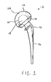
- FIG. 1 An articulating prosthesis 10 of the invention is illustrated in FIG. 1 as an articulating cup 12 in association with a proximal femoral endoprosthesis 14.
- the endoprosthesis 14 includes a stem portion 16 which is received within the medullary canal of a femur and a spherical head 18 which is articulatably matable with the articulating cup 12.
- the articulating cup 12 has a spherical inner surface 20 which is articulatably matable with the spherical head 18 and a substantially spherical outer surface 22 which is articulatably matable with a natural acetabulum.
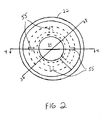
- the articulating cup 12 may be provided in several distinct pieces including a shell 24, a liner 26 and a locking liner portion 28.
- the cup 12 also includes a longitudinal axis 30, a superior apex 32 and an inferior aperture 34.
- the shell 24 is preferably formed from a biocompatible metal such as titanium, a titanium alloy or a stainless steel, and has an inner surface 36 and a spherical outer surface 22 adapted to articulate with a natural acetabulum.
- the outer surface 22 of shell 24 should be sized according to the size of the patent's acetabulum, and generally will have a diameter between about 36 and 80 millimeters.
- the liner 26 is preferably formed from a polymeric material, such as ultra high molecular weight polyethylene.
- the liner 26 has an outer surface 38, which matable to the inner surface 36 of the shell 24.
- the liner 26 also has a spherical inner surface 20 which is suited to articulate with the spherical head 18 of a femoral endoprosthesis 14.
- the spherical inner surface 20 of the liner 26 covers no more than one half of a sphere.
- the inner surface 20 of the liner 26 is hemispherical and the liner 26 is seated wholly within the shell 24.
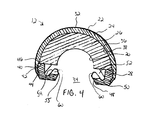
- the locking liner portion 28 may also be formed from a polymeric material such as ultra high molecular weight polyethylene. As shown in FIGS. 3-4, the locking liner portion 28 has a superior surface 40 that abuts the liner 26 within the shell 24. The locking liner portion 28 also has an inferior-facing, circumferential ledge 42 which abuts a similar, circumferential opposed ledge 44 provided on the inner surface 38 of the shell 24 proximate to the inferior aperture 34. The interlocking of the ledges 42, 44 secures the locking liner portion 28 against dissociation from the shell 24. In the embodiment of FIGS. 3 and 4, a portion of the superior surface 40 of the locking liner portion 28 also abuts an inferior facing ledge 46 on the inner surface 38 of the shell 24. In this embodiment, the locking liner portion 28 remains in its intended position and orientation within the shell 24 even if, for some reason, the liner 26 does not.
- a portion of the superior surface 40 of the locking liner portion 28 also abuts an inferior facing
- a locking element 48 extends from the locking liner portion 28.
- the locking element 48 is disposed around the periphery of the locking liner portion 28 proximate to the inferior aperture 34 of the cup 12 and extends inward, toward the longitudinal axis 30 of the cup 12, and in a superior direction toward the superior apex 32 of the cup 12.
- the locking element 48 extends from the liner locking portion 28, however, a person of ordinary skill in the art will recognize that other configurations are possible in keeping with the spirit of the invention.
- the liner 26 and the liner locking portion 28 could be provided as a single element with the locking element 48 extending from the combined liner.
- the locking element 48 preferably extends from a region 50 adjacent to the shell 24 and in proximity to the inferior aperture 34.
- the locking element 48 need not be disposed continuously around the periphery of the inferior aperture 34, but may consist of a plurality of discrete locking elements.
- the locking element 48 is resilient and may be deformed in response to an insertion force directed from the inferior aperture 34 towards the superior apex 32, such as the insertion force provided by the insertion of the spherical head 18 of a femoral endoprosthesis 14 into the inferior aperture 34 of the cup 12.
- a peripheral groove 52 may be disposed on the superior side 54 of the locking element 48 to provide clearance for the locking element 48 to deform.
- Longitudinal grooves 56 may also be provided to aid in the deforming of the locking element 48.
- the locking element 48 In response to an insertion force, the locking element 48 deforms from a first position (FIGS. 3 and 4) defining a first nominal diameter 56, outward and away from the longitudinal axis 30 of the cup 12 to define a second, larger diameter 58 (FIG. 5).
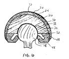
- the resilient locking element 48 then returns to its first position upon removal of the insertion force, such as when the spherical head 18 of a femoral endoprosthesis has been inserted past the locking element 48 to engage the spherical inner surface 20 of the liner 26 (FIG. 6).
- a head contacting portion 60 of the locking element 48 may be a spherical surface portion that, when the locking element is in its first position, defines a surface portion on a projection of the spherical inner surface 20 of the liner 26. In this way, the head contacting portion 60 will contact the spherical head 18 along a contact region.
- head contacting portion 60 configurations may be used, included including a rounded contacting portion (not shown) that contacts the spherical head 18 only at a point, or along a line around the periphery of the inferior aperture 34.
- the spherical head 18 will have a diameter 62 between about 22 and 32 millimeters.
- the first nominal diameter 54 is smaller than the diameter 62 of the spherical head 18, but the locking element 48 deforms to a second, larger diameter 56 that is at least as large as the diameter 62 of the spherical head 18.
- the head 18 deforms the locking element 48 upon insertion into the cap 12, passes through the locking element 48, and articulatably engages the inner surface 20 of the liner 26 as the locking element 48 returns to its original position.
- the head contacting portion 60 of the locking element 48 contacts the spherical head 18 to keep the spherical head 18 in contact with the spherical inner surface 20 of the liner 26 and to prevent dissociation of the head 18 from the cup 12. Should dissociation occur, the head 18 may be reinserted into the cup 12 by properly orienting the head 18 and providing an insertion force to push the head 18 through the locking element 48 as shown in FIGS. 5 and 6.
- the insertion force required to insert or reinsert the head 18 into the cup 12 is less than the subluxation force required to dissociate the head 18 from the cup 12 - making the head 18 difficult to dissociate from the cup 12, but making it easy to reinsert the head 18 should dissociation occur.
Abstract
Description
- The present invention relates to an articulating prosthesis having a locking element.
- In a hip hemiarthroplasty procedure, the proximal portion of a femur is replaced with a suitable prosthetic hip joint implant or implant assembly that articulatably mates directly with a patient's natural acetabulum. Two types of femoral prostheses are typically suitable for hip hemiarthroplasty procedures. One type is a bipolar prosthesis. In general, a bipolar hip prosthesis, such as disclosed in U.S. Patent Nos. 3,813,699 and 3,863,273, includes a shell having an external surface which articulates with a patient's acetabulum and an internal surface which articulates with the spherical head member of a prosthetic femoral component. The other type of prosthesis is often referred to as a unipolar endoprosthesis in which the prosthetic femoral component includes a spherical head member which is large enough to articulate directly with the acetabulum.
- One drawback to the successful use of bipolar hip prostheses is that they may become displaced after insertion. In particular, the spherical head of the femoral component may become dissociated from the shell. Such a dissociation may occur as the result of the abnormal twisting of a leg, or after a trauma such as a fall, such as might cause a dislocation in a natural hip joint. A problem with some prior art bipolar hip prostheses is that, in these situations, the dissociation can only be cured by further surgery.
- United States Patent No. 4,798,610 describes a bipolar femoral hip prosthesis having a floating locking ring that attempts to provide improvements over U.S. Patent No. 4,241,463. According to its disclosure, the spherical head of this femoral prosthesis does not dislocate from the shell. Rather, in response to forces that would dislocate a natural hip, the shell disengages from the acetabulum. The dislocation may then be corrected in a manner similar to the manner in which the dislocation of a natural hip is corrected.
- Dissociation of the components within the acetabulum is not necessarily preferred however. When correcting such a dissociation, it can be difficult to properly align the shell during correction. Also, dissociation of the components within the acetabulum and correction of such a condition can result in damage to the patient's natural bone. In addition, proper orientation of a floating locking ring, such as those described in U.S. Patent Nos. 4,241,463 and 4,798,610, can be problematic, even during normal use of the prosthesis.
- The present invention provides an articulating prosthesis having a cup and at least one resilient locking element. The cup includes a shell having a spherical outer surface shaped so as to articulate with a natural acetabulum and has a superior apex and an inferior aperture. A liner is provided on the inner surface of the shell. The liner, which may be formed from a polymeric material such as ultra high molecular weight polyethylene, has a spherical inner surface. The locking element is resilient and is disposed at least partially within the shell. The locking element extends inward, toward a longitudinal axis of the cup, and at least partially in a superior direction toward the apex of the cup.
- The locking element deforms, in response to an insertion force directed from the inferior aperture from a first position, defining a first nominal diameter, outward and away from the longitudinal axis of the cup to define a second, larger diameter. When the insertion force is removed, the resilient locking member returns to its original position. An end of the locking element may define a surface portion on a projection of the spherical inner surface of the liner when the locking element is in its first position.
- The articulating prosthesis may also include a stem member having a spherical head adapted to fit within and articulate with the spherical inner surface of the liner. The spherical head is sized so as to deform the locking element from its first position to its second position in response to an insertion force applied to the spherical head from an inferior direction, allowing the spherical head to pass through the second, larger diameter of the locking element and to articulatably engage the spherical inner surface of the liner. The spherical head is also sized so as to allow the resilient locking element to return to its first, nominal diameter after the spherical head has engaged the inner surface of the liner.
- The invention will be more fully understood by reference to the following detailed description when considered in conjunction with the accompanying drawings, in which:
- FIG. 1 is a side view of an articulating prosthesis of the invention having an articulating cup and an endoprosthesis component;
- FIG. 2 is an inferior view of an articulating cup of the invention;
- FIG. 3 is a cross sectional view of the cup of FIG. 2 taken along line 3-3;
- FIG. 4 is a cross sectional view of the cup of FIG. 2 taken along line 4-4;
- FIG. 5 is an exploded view of a spherical head of an endoprosthesis component partially inserted into the articulating cup of FIG. 2; and
- FIG. 6 is an exploded view of the spherical head and articulating cup of FIG. 5 with the head fully inserted.
-
- An
articulating prosthesis 10 of the invention is illustrated in FIG. 1 as anarticulating cup 12 in association with a proximalfemoral endoprosthesis 14. Theendoprosthesis 14 includes a stem portion 16 which is received within the medullary canal of a femur and aspherical head 18 which is articulatably matable with the articulatingcup 12. The articulatingcup 12 has a sphericalinner surface 20 which is articulatably matable with thespherical head 18 and a substantially sphericalouter surface 22 which is articulatably matable with a natural acetabulum. - As shown in FIGS. 2 to 4, the articulating
cup 12 may be provided in several distinct pieces including ashell 24, aliner 26 and alocking liner portion 28. Thecup 12 also includes a longitudinal axis 30, asuperior apex 32 and aninferior aperture 34. Theshell 24 is preferably formed from a biocompatible metal such as titanium, a titanium alloy or a stainless steel, and has aninner surface 36 and a sphericalouter surface 22 adapted to articulate with a natural acetabulum. Theouter surface 22 ofshell 24 should be sized according to the size of the patent's acetabulum, and generally will have a diameter between about 36 and 80 millimeters. - The
liner 26 is preferably formed from a polymeric material, such as ultra high molecular weight polyethylene. Theliner 26 has anouter surface 38, which matable to theinner surface 36 of theshell 24. Theliner 26 also has a sphericalinner surface 20 which is suited to articulate with thespherical head 18 of afemoral endoprosthesis 14. Preferably, the sphericalinner surface 20 of theliner 26 covers no more than one half of a sphere. In the embodiment of FIGS. 3-4, theinner surface 20 of theliner 26 is hemispherical and theliner 26 is seated wholly within theshell 24. - The
locking liner portion 28 may also be formed from a polymeric material such as ultra high molecular weight polyethylene. As shown in FIGS. 3-4, thelocking liner portion 28 has asuperior surface 40 that abuts theliner 26 within theshell 24. Thelocking liner portion 28 also has an inferior-facing,circumferential ledge 42 which abuts a similar, circumferential opposedledge 44 provided on theinner surface 38 of theshell 24 proximate to theinferior aperture 34. The interlocking of theledges locking liner portion 28 against dissociation from theshell 24. In the embodiment of FIGS. 3 and 4, a portion of thesuperior surface 40 of thelocking liner portion 28 also abuts an inferior facingledge 46 on theinner surface 38 of theshell 24. In this embodiment, thelocking liner portion 28 remains in its intended position and orientation within theshell 24 even if, for some reason, theliner 26 does not. - As shown in FIGS. 3 and 4, a
locking element 48 extends from thelocking liner portion 28. Thelocking element 48 is disposed around the periphery of thelocking liner portion 28 proximate to theinferior aperture 34 of thecup 12 and extends inward, toward the longitudinal axis 30 of thecup 12, and in a superior direction toward thesuperior apex 32 of thecup 12. - In the disclosed embodiments, the
locking element 48 extends from theliner locking portion 28, however, a person of ordinary skill in the art will recognize that other configurations are possible in keeping with the spirit of the invention. For example, theliner 26 and theliner locking portion 28 could be provided as a single element with thelocking element 48 extending from the combined liner. Generally, the lockingelement 48 preferably extends from aregion 50 adjacent to theshell 24 and in proximity to theinferior aperture 34. In addition, the lockingelement 48 need not be disposed continuously around the periphery of theinferior aperture 34, but may consist of a plurality of discrete locking elements. - The locking
element 48 is resilient and may be deformed in response to an insertion force directed from theinferior aperture 34 towards thesuperior apex 32, such as the insertion force provided by the insertion of thespherical head 18 of afemoral endoprosthesis 14 into theinferior aperture 34 of thecup 12. Aperipheral groove 52 may be disposed on thesuperior side 54 of the lockingelement 48 to provide clearance for the lockingelement 48 to deform.Longitudinal grooves 56 may also be provided to aid in the deforming of the lockingelement 48. - In response to an insertion force, the locking
element 48 deforms from a first position (FIGS. 3 and 4) defining a firstnominal diameter 56, outward and away from the longitudinal axis 30 of thecup 12 to define a second, larger diameter 58 (FIG. 5). Theresilient locking element 48 then returns to its first position upon removal of the insertion force, such as when thespherical head 18 of a femoral endoprosthesis has been inserted past the lockingelement 48 to engage the sphericalinner surface 20 of the liner 26 (FIG. 6). - A
head contacting portion 60 of the lockingelement 48 may be a spherical surface portion that, when the locking element is in its first position, defines a surface portion on a projection of the sphericalinner surface 20 of theliner 26. In this way, thehead contacting portion 60 will contact thespherical head 18 along a contact region. A person of ordinary skill in the art will understand, however, that otherhead contacting portion 60 configurations may be used, included including a rounded contacting portion (not shown) that contacts thespherical head 18 only at a point, or along a line around the periphery of theinferior aperture 34. - Generally, the
spherical head 18 will have adiameter 62 between about 22 and 32 millimeters. The firstnominal diameter 54 is smaller than thediameter 62 of thespherical head 18, but the lockingelement 48 deforms to a second,larger diameter 56 that is at least as large as thediameter 62 of thespherical head 18. In this way, thehead 18 deforms the lockingelement 48 upon insertion into thecap 12, passes through the lockingelement 48, and articulatably engages theinner surface 20 of theliner 26 as the lockingelement 48 returns to its original position. - Once the
spherical head 18 is fully inserted into thecup 12 and the lockingelement 48 returns to its original position, thehead contacting portion 60 of the lockingelement 48 contacts thespherical head 18 to keep thespherical head 18 in contact with the sphericalinner surface 20 of theliner 26 and to prevent dissociation of thehead 18 from thecup 12. Should dissociation occur, thehead 18 may be reinserted into thecup 12 by properly orienting thehead 18 and providing an insertion force to push thehead 18 through the lockingelement 48 as shown in FIGS. 5 and 6. Due to the structure of the lockingelement 48 of the invention, the insertion force required to insert or reinsert thehead 18 into thecup 12 is less than the subluxation force required to dissociate thehead 18 from the cup 12 - making thehead 18 difficult to dissociate from thecup 12, but making it easy to reinsert thehead 18 should dissociation occur. - Although the present invention is described with respect to particular embodiments and features and uses, numerous variations or equivalents are possible without taking away from the spirit or scope of the claimed invention. All references cited herein are expressly incorporated by reference in their entirety.
Claims (24)
- An articulating prosthesis comprising:a cup including a shell having a spherical outer surface and an inner surface, a liner matable with the inner surface of the shell and having a spherical inner surface, a longitudinal axis, an inferior aperture and a superior apex; andat least one resilient locking element disposed at least partially within the shell and extending from a region adjacent the inner surface of the shell inward toward the longitudinal axis of the cup and at least partially in a superior direction toward the apex of the cup.
- The prosthesis of claim 1, wherein the resilient locking element is deformable, in response to an insertion force directed from the inferior aperture, from a first position, defining a first nominal diameter, outward away from the longitudinal axis of the cup to define a second, larger diameter.
- The prosthesis of claim 2, wherein the resilient locking element returns to its first position upon removal of the insertion force.
- The prosthesis of claim 1, wherein the at least one locking element has a spherical surface portion that, when the at least one locking element is in its first position, defines a surface portion on a projection of the spherical inner surface of the liner.
- The prosthesis of claim 2, further comprising a stem member having a spherical head adapted to fit with and to articulate with the spherical inner surface of the liner.
- The prosthesis of claim 5, wherein the spherical head has a diameter larger than the first nominal diameter defined by the locking element.
- The prosthesis of claim 6, wherein the spherical head is sized so as to deform the locking element from its first position to its second position in response to an insertion force applied to the spherical head an inferior direction, allowing the spherical head to pass through the second, larger diameter of the locking element and to articulatably engage the spherical inner surface of the liner, the spherical head further being sized so as to allow the resilient locking element to return to its first, nominal diameter after the spherical head has engaged the inner surface of the liner.
- The prosthesis of claim 7, wherein the insertion force required to insert the spherical head through the inferior aperture to deform the at least one locking element and engage the inner surface of the liner is smaller than a subluxation force required to remove the spherical head from its engagement with the inner surface of the liner.
- The prosthesis of claim 5, wherein the articulating prosthesis is a bipolar, hemiarthroplasty hip prosthesis.
- The prosthesis of claim 9, wherein the spherical outer surface of the shell is adapted to articulate with an acetabulum.
- The prosthesis of claim 9, wherein the stem is matable with a femur.
- The prosthesis of claim 9, wherein reinsertion of the spherical head into the cup following subluxation of the spherical head from the cup after installation of the prosthesis within a patient may be performed without surgery.
- An articulating prosthesis comprising:a cup including a shell having a spherical outer surface and an inner surface, a liner matable with the inner surface of the shell and having a spherical inner surface, a longitudinal axis, an inferior aperture and a superior apex;at least one resilient locking element disposed at least partially within the shell and extending from a region adjacent the inner surface of the shell inward toward the longitudinal axis of the cup and at least partially in a superior direction toward the apex of the cup, the resilient locking element is deformable, in response to an insertion force directed from the inferior aperture, from a first position, defining a first nominal diameter, outward away from the longitudinal axis of the cup to define a second, larger diameter and returns to its first position upon removal of the insertion force; anda stem member having a spherical head adapted to fit within and to articulate with the spherical inner surface of the liner;wherein the spherical head is sized so as to deform the locking element from its first position to its second position in response to an insertion force applied to the spherical head from an inferior direction, allowing the spherical head to pass through the second, larger diameter of the locking element and to articulatably engage the spherical inner surface of the liner, the spherical head further being sized so as to allow the resilient locking element to return to its first, nominal diameter after the spherical head has engaged the inner surface of the liner.
- The prosthesis of claim 2 or claim 13, further comprising a groove formed in the liner adjacent to a superior surface of the at least one resilient locking element, the groove providing clearance for the resilient locking element to deform in response to an insertion force directed from the inferior aperture.
- The prosthesis of claim 14, wherein the at least one locking element extends around a perimeter of the aperture.
- The prosthesis of claim 15, wherein the groove extends around the perimeter of the aperture.
- The prosthesis of claim 16, wherein at least one longitudinal groove is formed in the at least one locking element.
- The prosthesis of claim 7 or claim 13, wherein the spherical head has a diameter that is substantially equal to a diameter of the spherical inner surface of the liner, the value of each diameter being between about 22 and 32 millimeters.
- The prosthesis of claim 2 or claim 13, wherein a diameter of the spherical outer surface of the shell is between about 36 and 80 millimeters.
- The prosthesis of claim 2 or claim 13, wherein the locking element is made from ultra high molecular weight polyethylene.
- The prosthesis of claim 20, wherein the shell is made from a metal.
- A bipolar hemiarthroplasty hip prosthesis comprising:wherein the spherical head is sized so as to deform the locking element from its first position to its second position in response to an insertion force applied to the spherical head an inferior direction, allowing the spherical head to pass through the second, larger diameter of the locking element and to articulatably engage the spherical inner surface of the liner, the spherical head further being sized so as to allow the resilient locking element to return to its first, nominal diameter after the spherical head has engaged the inner surface of the liner.a cup including a shell having a spherical outer surface adapted to articulate with an acetabulum and an inner surface, a liner matable with the inner surface of the shell and having a spherical inner surface, a longitudinal axis, an inferior aperture and a superior apex;at least one resilient locking element disposed at least partially within the shell and extending from a region adjacent the inner surface of the shell inward toward the longitudinal axis of the cup and at least partially in a superior direction toward the apex of the cup, the resilient locking element is deformable, in response to an insertion force directed from the inferior aperture, from a first position, defining a first nominal diameter, outward away from the longitudinal axis of the cup to define a second, larger diameter and returns to its first position upon removal of the insertion force; anda stem member matable with a femur and having a spherical head adapted to fit with and to articulate with the spherical inner surface of the liner;
- The prosthesis of claim 22, wherein reinsertion of the spherical head into the cup following subluxation of the spherical head from the cup after installation of the prosthesis within a patient may be performed without surgery.
- The prosthesis of claim 22, wherein the insertion force required to insert the spherical head through the inferior aperture to deform the at least one locking element and engage the inner surface of the liner is smaller than a subluxation force required to remove the spherical head from its engagement with the inner surface of the liner.
Applications Claiming Priority (2)
| Application Number | Priority Date | Filing Date | Title |
|---|---|---|---|
| US09/049,452 US6206929B1 (en) | 1998-03-27 | 1998-03-27 | Bipolar hip prosthesis with locking head |
| US49452 | 1998-03-27 |
Publications (3)
| Publication Number | Publication Date |
|---|---|
| EP0945109A2 true EP0945109A2 (en) | 1999-09-29 |
| EP0945109A3 EP0945109A3 (en) | 2000-01-12 |
| EP0945109B1 EP0945109B1 (en) | 2004-11-03 |
Family
ID=21959887
Family Applications (1)
| Application Number | Title | Priority Date | Filing Date |
|---|---|---|---|
| EP99302386A Expired - Lifetime EP0945109B1 (en) | 1998-03-27 | 1999-03-26 | Bipolar hip prosthesis with locking head |
Country Status (4)
| Country | Link |
|---|---|
| US (1) | US6206929B1 (en) |
| EP (1) | EP0945109B1 (en) |
| JP (1) | JP4204691B2 (en) |
| DE (1) | DE69921526T2 (en) |
Cited By (15)
| Publication number | Priority date | Publication date | Assignee | Title |
|---|---|---|---|---|
| WO2002058597A2 (en) * | 2001-01-25 | 2002-08-01 | Smith & Nephew, Inc. | Containment system for constraining a prosthetic component |
| WO2004024036A1 (en) * | 2002-09-13 | 2004-03-25 | Smith & Nephew, Inc. | Prostheses |
| FR2849769A1 (en) * | 2003-01-13 | 2004-07-16 | Biotechni | Implant for artificial-joint of e.g. hip, has secondary piece drowned in primary piece, and stem of secondary implant that comes in contact with edge of primary piece with beveled edge |
| US6916342B2 (en) | 2002-04-01 | 2005-07-12 | Smith & Nephew, Inc. | Liner assembly for prosthetic components |
| FR2868687A1 (en) * | 2004-04-09 | 2005-10-14 | Ct Pulse France Sa Sa | Acetabular copula for hip prosthesis, has annular pad that retains femoral rod in insert and that is placed apart from spherical portion that extends from equator of insert |
| EP1611869A1 (en) * | 2004-06-30 | 2006-01-04 | DePuy Products, Inc. | Extended radius prosthesis |
| GB2438170A (en) * | 2006-05-19 | 2007-11-21 | Matz Internat Fze | Ball and socket joint prosthesis with ball retaining means and an axially split screw |
| WO2011005191A1 (en) * | 2009-07-10 | 2011-01-13 | Milux Holding S.A. | Hip joint device and method |
| US7955395B2 (en) | 2004-03-11 | 2011-06-07 | Smith & Nephew, Inc. | Universal liner |
| US8123815B2 (en) | 2008-11-24 | 2012-02-28 | Biomet Manufacturing Corp. | Multiple bearing acetabular prosthesis |
| EP2451392A1 (en) * | 2009-07-10 | 2012-05-16 | Milux Holding SA | Hip joint device and method |
| EP2451388A1 (en) * | 2009-07-10 | 2012-05-16 | Milux Holding SA | Hip joint device |
| US8308810B2 (en) | 2009-07-14 | 2012-11-13 | Biomet Manufacturing Corp. | Multiple bearing acetabular prosthesis |
| US8679187B2 (en) | 2006-03-20 | 2014-03-25 | Smith & Nephew, Inc. | Acetabular cup assembly for multiple bearing materials |
| EP3170478A1 (en) * | 2009-07-10 | 2017-05-24 | Kirk Promotion LTD. | Hip joint device |
Families Citing this family (26)
| Publication number | Priority date | Publication date | Assignee | Title |
|---|---|---|---|---|
| US20050033445A1 (en) * | 2003-08-05 | 2005-02-10 | Thomas Siebel | Hip joint prosthesis |
| DE202006009757U1 (en) | 2006-05-02 | 2006-08-31 | Ceram Tec Ag Innovative Ceramic Engineering | Package for adapter sleeves for hip endoprostheses comprises hollow stud, over which sleeve fits, bottom section of stud being pressed down until it contacts package base when ball is fitted on to adapter, ensuring correct force is used |
| DE102007031667A1 (en) * | 2006-08-04 | 2008-02-14 | Ceramtec Ag Innovative Ceramic Engineering | Insertion of vibration-damping elements in prosthetic systems for manipulation and damping of natural frequencies |
| US8029574B2 (en) * | 2006-11-07 | 2011-10-04 | Biomedflex Llc | Prosthetic knee joint |
| US8070823B2 (en) * | 2006-11-07 | 2011-12-06 | Biomedflex Llc | Prosthetic ball-and-socket joint |
| WO2008058205A1 (en) | 2006-11-07 | 2008-05-15 | Biomedflex, Llc | Medical implants |
| US9005307B2 (en) | 2006-11-07 | 2015-04-14 | Biomedflex, Llc | Prosthetic ball-and-socket joint |
| US20110166671A1 (en) * | 2006-11-07 | 2011-07-07 | Kellar Franz W | Prosthetic joint |
| US8308812B2 (en) | 2006-11-07 | 2012-11-13 | Biomedflex, Llc | Prosthetic joint assembly and joint member therefor |
| US8512413B2 (en) | 2006-11-07 | 2013-08-20 | Biomedflex, Llc | Prosthetic knee joint |
| US7905919B2 (en) * | 2006-11-07 | 2011-03-15 | Biomedflex Llc | Prosthetic joint |
| US8562616B2 (en) | 2007-10-10 | 2013-10-22 | Biomet Manufacturing, Llc | Knee joint prosthesis system and method for implantation |
| US8187280B2 (en) | 2007-10-10 | 2012-05-29 | Biomet Manufacturing Corp. | Knee joint prosthesis system and method for implantation |
| US8328873B2 (en) | 2007-01-10 | 2012-12-11 | Biomet Manufacturing Corp. | Knee joint prosthesis system and method for implantation |
| US8163028B2 (en) | 2007-01-10 | 2012-04-24 | Biomet Manufacturing Corp. | Knee joint prosthesis system and method for implantation |
| US8157869B2 (en) | 2007-01-10 | 2012-04-17 | Biomet Manufacturing Corp. | Knee joint prosthesis system and method for implantation |
| US8840676B2 (en) * | 2009-05-07 | 2014-09-23 | Smith & Nephew, Inc. | Modular trial heads for a prosthetic |
| EP2451399B1 (en) * | 2009-07-10 | 2015-12-23 | Kirk Promotion LTD. | Hip joint device |
| US11039929B2 (en) * | 2009-07-10 | 2021-06-22 | Peter Mats Forsell | Hip joint device and method |
| US8585769B2 (en) | 2011-01-14 | 2013-11-19 | Zimmer, Inc. | Acetabular liner system |
| US9023112B2 (en) | 2011-02-24 | 2015-05-05 | Depuy (Ireland) | Maintaining proper mechanics THA |
| US9668745B2 (en) | 2011-12-19 | 2017-06-06 | Depuy Ireland Unlimited Company | Anatomical concentric spheres THA |
| US8858645B2 (en) | 2012-06-21 | 2014-10-14 | DePuy Synthes Products, LLC | Constrained mobile bearing hip assembly |
| WO2017214095A1 (en) * | 2016-06-07 | 2017-12-14 | Holiday Ron | Flexible constrained liner for hip prosthesis |
| KR101837301B1 (en) | 2016-10-28 | 2018-03-12 | 경북대학교 산학협력단 | Surgical navigation system |
| KR20210086640A (en) * | 2018-10-03 | 2021-07-08 | 토르니에, 인코포레이티드 | elbow joint prosthesis |
Citations (4)
| Publication number | Priority date | Publication date | Assignee | Title |
|---|---|---|---|---|
| US3813699A (en) | 1973-01-15 | 1974-06-04 | R Giliberty | Prosthetic hip joint |
| US3863273A (en) | 1973-09-20 | 1975-02-04 | Meditec Inc | Orthopedic prosthetic implant devices |
| US4241463A (en) | 1978-10-16 | 1980-12-30 | Precision Cast Specialties, Inc. | Prosthetic implant device |
| US4798610A (en) | 1982-09-29 | 1989-01-17 | Osteonics Corp. | Prosthetic implant device |
Family Cites Families (12)
| Publication number | Priority date | Publication date | Assignee | Title |
|---|---|---|---|---|
| US4044403A (en) * | 1976-11-01 | 1977-08-30 | Howmedica, Inc. | Implantable joint prosthesis |
| US4172296A (en) * | 1978-02-01 | 1979-10-30 | Howmedica, Inc. | Bicentric joint prosthesis |
| FR2582934B1 (en) * | 1985-06-10 | 1989-07-07 | Moulin Jacques | TOTAL HIP PROSTHESIS WITH LONG-TERM ACTION PROHIBITING ALL LUXATION |
| FR2583634B1 (en) * | 1985-06-24 | 1991-05-24 | Tornier Sa | RETENTION SYSTEM FOR OSTEOSYNTHESIS DEVICES |
| US4770658A (en) | 1987-05-01 | 1988-09-13 | Zimmer, Inc. | Joint prosthesis |
| JP2543747B2 (en) * | 1988-05-31 | 1996-10-16 | 日本特殊陶業株式会社 | Artificial head |
| US5062853A (en) * | 1989-08-08 | 1991-11-05 | Forte Mark R | Bipolar femoral implant |
| JP2799224B2 (en) * | 1990-06-12 | 1998-09-17 | ヤンマーディーゼル株式会社 | Joint prosthesis |
| US5156626A (en) | 1990-06-29 | 1992-10-20 | Zimmer, Inc. | Set of provisional prosthesis instrumentation |
| EP0600024A1 (en) | 1991-08-20 | 1994-06-08 | Exactech, Inc. | Bipolar endoprosthesis |
| FR2701206A1 (en) * | 1993-02-09 | 1994-08-12 | Medinov Sa | Impacter equipment for a polyethylene core or cup for acetabular implant |
| JPH08651A (en) * | 1994-06-23 | 1996-01-09 | Ngk Spark Plug Co Ltd | Artificial bone capital |
-
1998
- 1998-03-27 US US09/049,452 patent/US6206929B1/en not_active Expired - Fee Related
-
1999
- 1999-03-26 DE DE69921526T patent/DE69921526T2/en not_active Expired - Fee Related
- 1999-03-26 EP EP99302386A patent/EP0945109B1/en not_active Expired - Lifetime
- 1999-03-26 JP JP08473899A patent/JP4204691B2/en not_active Expired - Fee Related
Patent Citations (4)
| Publication number | Priority date | Publication date | Assignee | Title |
|---|---|---|---|---|
| US3813699A (en) | 1973-01-15 | 1974-06-04 | R Giliberty | Prosthetic hip joint |
| US3863273A (en) | 1973-09-20 | 1975-02-04 | Meditec Inc | Orthopedic prosthetic implant devices |
| US4241463A (en) | 1978-10-16 | 1980-12-30 | Precision Cast Specialties, Inc. | Prosthetic implant device |
| US4798610A (en) | 1982-09-29 | 1989-01-17 | Osteonics Corp. | Prosthetic implant device |
Cited By (36)
| Publication number | Priority date | Publication date | Assignee | Title |
|---|---|---|---|---|
| WO2002058597A3 (en) * | 2001-01-25 | 2003-10-30 | Smith & Nephew Inc | Containment system for constraining a prosthetic component |
| US7749277B2 (en) | 2001-01-25 | 2010-07-06 | Smith & Nephew, Inc. | Containment system for constraining a prosthetic component |
| US7335231B2 (en) | 2001-01-25 | 2008-02-26 | Smith & Nephew, Inc. | Containment system for constraining a prosthetic component |
| WO2002058597A2 (en) * | 2001-01-25 | 2002-08-01 | Smith & Nephew, Inc. | Containment system for constraining a prosthetic component |
| US8029571B2 (en) | 2001-01-25 | 2011-10-04 | Smith & Nephew, Inc. | Containment system for constraining a prosthetic component |
| US8790412B2 (en) | 2001-01-25 | 2014-07-29 | Smith & Nephew, Inc. | Containment system for constraining a prosthetic component |
| US8029572B2 (en) | 2001-01-25 | 2011-10-04 | Smith & Nephew, Inc. | Containment system for constraining a prosthetic component |
| US7160332B2 (en) | 2002-04-01 | 2007-01-09 | Smith & Nephew, Inc. | Line assembly for prosthetic components |
| US6916342B2 (en) | 2002-04-01 | 2005-07-12 | Smith & Nephew, Inc. | Liner assembly for prosthetic components |
| US6986792B2 (en) | 2002-09-13 | 2006-01-17 | Smith & Nephew, Inc. | Prostheses |
| AU2003296403B2 (en) * | 2002-09-13 | 2009-06-04 | Smith & Nephew, Inc. | Prostheses |
| WO2004024036A1 (en) * | 2002-09-13 | 2004-03-25 | Smith & Nephew, Inc. | Prostheses |
| WO2004071332A3 (en) * | 2003-01-13 | 2004-09-30 | Biotechni | Implant and articular prosthesis comprising said implant |
| WO2004071332A2 (en) * | 2003-01-13 | 2004-08-26 | Biotechni | Implant and articular prosthesis comprising said implant |
| FR2849769A1 (en) * | 2003-01-13 | 2004-07-16 | Biotechni | Implant for artificial-joint of e.g. hip, has secondary piece drowned in primary piece, and stem of secondary implant that comes in contact with edge of primary piece with beveled edge |
| US7955395B2 (en) | 2004-03-11 | 2011-06-07 | Smith & Nephew, Inc. | Universal liner |
| FR2868687A1 (en) * | 2004-04-09 | 2005-10-14 | Ct Pulse France Sa Sa | Acetabular copula for hip prosthesis, has annular pad that retains femoral rod in insert and that is placed apart from spherical portion that extends from equator of insert |
| EP1611869A1 (en) * | 2004-06-30 | 2006-01-04 | DePuy Products, Inc. | Extended radius prosthesis |
| US8163029B2 (en) | 2004-06-30 | 2012-04-24 | Depuy Products, Inc. | Extended radius prosthesis and associated method |
| US8679187B2 (en) | 2006-03-20 | 2014-03-25 | Smith & Nephew, Inc. | Acetabular cup assembly for multiple bearing materials |
| WO2007135572A2 (en) * | 2006-05-19 | 2007-11-29 | Matz International Fze | Joint prosthesis |
| GB2438170A (en) * | 2006-05-19 | 2007-11-21 | Matz Internat Fze | Ball and socket joint prosthesis with ball retaining means and an axially split screw |
| WO2007135572A3 (en) * | 2006-05-19 | 2009-03-19 | Matz Internat Fze | Joint prosthesis |
| US8123815B2 (en) | 2008-11-24 | 2012-02-28 | Biomet Manufacturing Corp. | Multiple bearing acetabular prosthesis |
| US9445903B2 (en) | 2008-11-24 | 2016-09-20 | Biomet Manufacturing, Llc | Multi-bearing acetabular prosthesis |
| EP2451397A1 (en) * | 2009-07-10 | 2012-05-16 | Milux Holding SA | Hip joint device and method |
| EP2451388A1 (en) * | 2009-07-10 | 2012-05-16 | Milux Holding SA | Hip joint device |
| EP2451388A4 (en) * | 2009-07-10 | 2012-12-12 | Milux Holding Sa | Hip joint device |
| EP2451392A4 (en) * | 2009-07-10 | 2013-04-24 | Milux Holding Sa | Hip joint device and method |
| EP2451397A4 (en) * | 2009-07-10 | 2013-07-10 | Milux Holding Sa | Hip joint device and method |
| EP2451392A1 (en) * | 2009-07-10 | 2012-05-16 | Milux Holding SA | Hip joint device and method |
| WO2011005191A1 (en) * | 2009-07-10 | 2011-01-13 | Milux Holding S.A. | Hip joint device and method |
| US9180014B2 (en) | 2009-07-10 | 2015-11-10 | Peter Forsell | Hip joint device and method |
| EP3170478A1 (en) * | 2009-07-10 | 2017-05-24 | Kirk Promotion LTD. | Hip joint device |
| US8308810B2 (en) | 2009-07-14 | 2012-11-13 | Biomet Manufacturing Corp. | Multiple bearing acetabular prosthesis |
| US9445904B2 (en) | 2009-07-14 | 2016-09-20 | Biomet Manufacturing, Llc | Multiple bearing acetabular prosthesis |
Also Published As
| Publication number | Publication date |
|---|---|
| DE69921526D1 (en) | 2004-12-09 |
| EP0945109B1 (en) | 2004-11-03 |
| JPH11309163A (en) | 1999-11-09 |
| US6206929B1 (en) | 2001-03-27 |
| EP0945109A3 (en) | 2000-01-12 |
| DE69921526T2 (en) | 2005-11-24 |
| JP4204691B2 (en) | 2009-01-07 |
Similar Documents
| Publication | Publication Date | Title |
|---|---|---|
| US6206929B1 (en) | Bipolar hip prosthesis with locking head | |
| EP1506749B1 (en) | Constrained acetabular liner | |
| US7115145B2 (en) | Acetabular component | |
| EP1304980B1 (en) | Monopolar constrained acetabular component | |
| EP1945146B1 (en) | Rotating constrained liner | |
| US5263988A (en) | Bipolar endoprosthesis | |
| US4798610A (en) | Prosthetic implant device | |
| EP0394545B1 (en) | Stepped-lock ring system for implantable joint prostheses | |
| EP0239210B1 (en) | Locking mechanism for prosthesis components | |
| EP1197192B1 (en) | Constrained socket for use with a ball-and-socket joint | |
| US20110054628A1 (en) | Reflex fixation geometry revision and reconstruction system reverse articulation | |
| AU2001276975A1 (en) | Monopolar constrained acetabular component | |
| US20200129298A1 (en) | Novel design for a joint implant | |
| US20060206211A1 (en) | Bipolar hip prosthesis with free floating ring | |
| US20070032878A1 (en) | Acetabular liner | |
| AU7932901A (en) | Constrained socket for use with a ball-and-socket joint |
Legal Events
| Date | Code | Title | Description |
|---|---|---|---|
| PUAI | Public reference made under article 153(3) epc to a published international application that has entered the european phase |
Free format text: ORIGINAL CODE: 0009012 |
|
| AK | Designated contracting states |
Kind code of ref document: A2 Designated state(s): DE FR GB IE IT |
|
| AX | Request for extension of the european patent |
Free format text: AL;LT;LV;MK;RO;SI |
|
| PUAL | Search report despatched |
Free format text: ORIGINAL CODE: 0009013 |
|
| AK | Designated contracting states |
Kind code of ref document: A3 Designated state(s): AT BE CH CY DE DK ES FI FR GB GR IE IT LI LU MC NL PT SE |
|
| AX | Request for extension of the european patent |
Free format text: AL;LT;LV;MK;RO;SI |
|
| RIN1 | Information on inventor provided before grant (corrected) |
Inventor name: KHALILI, FARID BRUCE Inventor name: OCHOA, JORGE |
|
| 17P | Request for examination filed |
Effective date: 20000616 |
|
| AKX | Designation fees paid |
Free format text: DE FR GB IE IT |
|
| RAP1 | Party data changed (applicant data changed or rights of an application transferred) |
Owner name: DEPUY PRODUCTS, INC. |
|
| 17Q | First examination report despatched |
Effective date: 20030224 |
|
| RAP1 | Party data changed (applicant data changed or rights of an application transferred) |
Owner name: DEPUY PRODUCTS, INC. |
|
| GRAP | Despatch of communication of intention to grant a patent |
Free format text: ORIGINAL CODE: EPIDOSNIGR1 |
|
| GRAS | Grant fee paid |
Free format text: ORIGINAL CODE: EPIDOSNIGR3 |
|
| GRAA | (expected) grant |
Free format text: ORIGINAL CODE: 0009210 |
|
| AK | Designated contracting states |
Kind code of ref document: B1 Designated state(s): DE FR GB IE IT |
|
| PG25 | Lapsed in a contracting state [announced via postgrant information from national office to epo] |
Ref country code: IT Free format text: LAPSE BECAUSE OF FAILURE TO SUBMIT A TRANSLATION OF THE DESCRIPTION OR TO PAY THE FEE WITHIN THE PRESCRIBED TIME-LIMIT;WARNING: LAPSES OF ITALIAN PATENTS WITH EFFECTIVE DATE BEFORE 2007 MAY HAVE OCCURRED AT ANY TIME BEFORE 2007. THE CORRECT EFFECTIVE DATE MAY BE DIFFERENT FROM THE ONE RECORDED. Effective date: 20041103 |
|
| REG | Reference to a national code |
Ref country code: GB Ref legal event code: FG4D |
|
| REF | Corresponds to: |
Ref document number: 69921526 Country of ref document: DE Date of ref document: 20041209 Kind code of ref document: P |
|
| REG | Reference to a national code |
Ref country code: IE Ref legal event code: FG4D |
|
| PLBE | No opposition filed within time limit |
Free format text: ORIGINAL CODE: 0009261 |
|
| STAA | Information on the status of an ep patent application or granted ep patent |
Free format text: STATUS: NO OPPOSITION FILED WITHIN TIME LIMIT |
|
| ET | Fr: translation filed | ||
| 26N | No opposition filed |
Effective date: 20050804 |
|
| PGFP | Annual fee paid to national office [announced via postgrant information from national office to epo] |
Ref country code: IE Payment date: 20080313 Year of fee payment: 10 Ref country code: GB Payment date: 20080326 Year of fee payment: 10 |
|
| PGFP | Annual fee paid to national office [announced via postgrant information from national office to epo] |
Ref country code: FR Payment date: 20080311 Year of fee payment: 10 Ref country code: DE Payment date: 20080407 Year of fee payment: 10 |
|
| GBPC | Gb: european patent ceased through non-payment of renewal fee |
Effective date: 20090326 |
|
| REG | Reference to a national code |
Ref country code: FR Ref legal event code: ST Effective date: 20091130 |
|
| REG | Reference to a national code |
Ref country code: IE Ref legal event code: MM4A |
|
| PG25 | Lapsed in a contracting state [announced via postgrant information from national office to epo] |
Ref country code: IE Free format text: LAPSE BECAUSE OF NON-PAYMENT OF DUE FEES Effective date: 20090326 Ref country code: DE Free format text: LAPSE BECAUSE OF NON-PAYMENT OF DUE FEES Effective date: 20091001 |
|
| PG25 | Lapsed in a contracting state [announced via postgrant information from national office to epo] |
Ref country code: GB Free format text: LAPSE BECAUSE OF NON-PAYMENT OF DUE FEES Effective date: 20090326 Ref country code: FR Free format text: LAPSE BECAUSE OF NON-PAYMENT OF DUE FEES Effective date: 20091123 |