EP0945828A2 - Portable electronic device with contacting and noncontacting interfaces - Google Patents
Portable electronic device with contacting and noncontacting interfaces Download PDFInfo
- Publication number
- EP0945828A2 EP0945828A2 EP99103878A EP99103878A EP0945828A2 EP 0945828 A2 EP0945828 A2 EP 0945828A2 EP 99103878 A EP99103878 A EP 99103878A EP 99103878 A EP99103878 A EP 99103878A EP 0945828 A2 EP0945828 A2 EP 0945828A2
- Authority
- EP
- European Patent Office
- Prior art keywords
- interface
- contacting
- noncontacting
- portable electronic
- electronic device
- Prior art date
- Legal status (The legal status is an assumption and is not a legal conclusion. Google has not performed a legal analysis and makes no representation as to the accuracy of the status listed.)
- Granted
Links
Images


Classifications
-
- G—PHYSICS
- G06—COMPUTING; CALCULATING OR COUNTING
- G06K—GRAPHICAL DATA READING; PRESENTATION OF DATA; RECORD CARRIERS; HANDLING RECORD CARRIERS
- G06K19/00—Record carriers for use with machines and with at least a part designed to carry digital markings
-
- G—PHYSICS
- G06—COMPUTING; CALCULATING OR COUNTING
- G06K—GRAPHICAL DATA READING; PRESENTATION OF DATA; RECORD CARRIERS; HANDLING RECORD CARRIERS
- G06K19/00—Record carriers for use with machines and with at least a part designed to carry digital markings
- G06K19/06—Record carriers for use with machines and with at least a part designed to carry digital markings characterised by the kind of the digital marking, e.g. shape, nature, code
- G06K19/067—Record carriers with conductive marks, printed circuits or semiconductor circuit elements, e.g. credit or identity cards also with resonating or responding marks without active components
- G06K19/07—Record carriers with conductive marks, printed circuits or semiconductor circuit elements, e.g. credit or identity cards also with resonating or responding marks without active components with integrated circuit chips
- G06K19/077—Constructional details, e.g. mounting of circuits in the carrier
- G06K19/07749—Constructional details, e.g. mounting of circuits in the carrier the record carrier being capable of non-contact communication, e.g. constructional details of the antenna of a non-contact smart card
- G06K19/07766—Constructional details, e.g. mounting of circuits in the carrier the record carrier being capable of non-contact communication, e.g. constructional details of the antenna of a non-contact smart card comprising at least a second communication arrangement in addition to a first non-contact communication arrangement
- G06K19/07769—Constructional details, e.g. mounting of circuits in the carrier the record carrier being capable of non-contact communication, e.g. constructional details of the antenna of a non-contact smart card comprising at least a second communication arrangement in addition to a first non-contact communication arrangement the further communication means being a galvanic interface, e.g. hybrid or mixed smart cards having a contact and a non-contact interface
-
- G—PHYSICS
- G06—COMPUTING; CALCULATING OR COUNTING
- G06K—GRAPHICAL DATA READING; PRESENTATION OF DATA; RECORD CARRIERS; HANDLING RECORD CARRIERS
- G06K19/00—Record carriers for use with machines and with at least a part designed to carry digital markings
- G06K19/06—Record carriers for use with machines and with at least a part designed to carry digital markings characterised by the kind of the digital marking, e.g. shape, nature, code
- G06K19/067—Record carriers with conductive marks, printed circuits or semiconductor circuit elements, e.g. credit or identity cards also with resonating or responding marks without active components
- G06K19/07—Record carriers with conductive marks, printed circuits or semiconductor circuit elements, e.g. credit or identity cards also with resonating or responding marks without active components with integrated circuit chips
- G06K19/0723—Record carriers with conductive marks, printed circuits or semiconductor circuit elements, e.g. credit or identity cards also with resonating or responding marks without active components with integrated circuit chips the record carrier comprising an arrangement for non-contact communication, e.g. wireless communication circuits on transponder cards, non-contact smart cards or RFIDs
-
- G—PHYSICS
- G06—COMPUTING; CALCULATING OR COUNTING
- G06K—GRAPHICAL DATA READING; PRESENTATION OF DATA; RECORD CARRIERS; HANDLING RECORD CARRIERS
- G06K19/00—Record carriers for use with machines and with at least a part designed to carry digital markings
- G06K19/06—Record carriers for use with machines and with at least a part designed to carry digital markings characterised by the kind of the digital marking, e.g. shape, nature, code
- G06K19/067—Record carriers with conductive marks, printed circuits or semiconductor circuit elements, e.g. credit or identity cards also with resonating or responding marks without active components
- G06K19/07—Record carriers with conductive marks, printed circuits or semiconductor circuit elements, e.g. credit or identity cards also with resonating or responding marks without active components with integrated circuit chips
- G06K19/077—Constructional details, e.g. mounting of circuits in the carrier
-
- G—PHYSICS
- G06—COMPUTING; CALCULATING OR COUNTING
- G06K—GRAPHICAL DATA READING; PRESENTATION OF DATA; RECORD CARRIERS; HANDLING RECORD CARRIERS
- G06K7/00—Methods or arrangements for sensing record carriers, e.g. for reading patterns
- G06K7/0008—General problems related to the reading of electronic memory record carriers, independent of its reading method, e.g. power transfer
Landscapes
- Engineering & Computer Science (AREA)
- General Physics & Mathematics (AREA)
- Theoretical Computer Science (AREA)
- Physics & Mathematics (AREA)
- Computer Hardware Design (AREA)
- Microelectronics & Electronic Packaging (AREA)
- Computer Vision & Pattern Recognition (AREA)
- Artificial Intelligence (AREA)
- Computer Networks & Wireless Communication (AREA)
- Credit Cards Or The Like (AREA)
- Mobile Radio Communication Systems (AREA)
- Coupling Device And Connection With Printed Circuit (AREA)
- Near-Field Transmission Systems (AREA)
Abstract
Description
Claims (20)
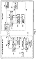
- A portable electronic device comprising:a contacting interface (401) including a plurality of contact terminals (C1 to C8) for exchanging driving power and data, anda noncontacting interface (400) for generating driving power and demodulating received data from a signal received via an antenna (301a),
characterized in the said device further comprisesinhibiting means (405) for inhibiting an operation of the other one of said contacting and noncontacting interfaces (401, 400) while said portable electronic device is driven via one of said contacting and noncontacting interfaces (401, 400). - A device according to claim 1, characterized in that said inhibiting means (405) comprises first inhibiting means (SW1) for inhibiting an operation of said noncontacting interface while said portable electronic device is driven via said contacting interface (401).
- A device according to claim 2, characterized in that said first inhibiting means (SW1) inhibits an operation of said noncontacting interface by cutting off conduction between an antenna coil (301a) and said noncontacting interface (400) while said portable electronic device is driven via said contacting interface (401).
- A device according to claim 3, characterized in thatsaid first inhibiting means (SW1) comprises a switch (SW1) for turning on and off the conduction between said antenna (301a) coil and said noncontacting interface (401), andturns off said switch (SW1) while a driving voltage is applied to said portable electronic device via said contacting interface (401).
- A device according to claim 2, characterized by further comprising a control circuit (405) for processing data received via said contacting or noncontacting interface (401, 400),
wherein said first inhibiting means (SW1) comprises a switch (312 to 315) for turning on and off conduction between said control circuit (405) and said noncontacting interface (400), andturns off said switch (312 to 315) while a driving voltage is applied to said portable electronic device via said contacting interface (401). - A device according to claim 2, characterized in that said inhibiting means (405) comprises second inhibiting means (317 to 320) for inhibiting a signal input and output via said contacting interface (401) while said portable electronic device is driven via said noncontacting interface (400).
- A device according to claim 5, characterized by further comprising a control circuit (405) for processing data received via said contacting or noncontacting interface (401, 400),
wherein said second inhibiting means (317 to 320) cuts off conduction between said contacting interface (401) and said control circuit (405) while said portable electronic device is driven via said noncontacting interface (400). - A device according to claim 7, characterized in thatsaid second inhibiting means (317 to 320) comprises a switch (317 to 320) for turning on and off conduction between said control circuit (405) and said contacting interface (401), andturns off said switch (317 to 320) while a driving voltage is applied to said portable electronic device via said noncontacting interface (400).
- A portable electronic device comprising contacting and noncontacting interfaces (401, 400) and a control circuit (405) connected to said contacting and noncontacting interfaces (401, 400), and is driven by said contacting or noncontacting interface (401, 400),
characterized in that said device further comprising:detecting means (405) for detecting whether said portable electronic device is driven via said contacting or noncontacting interface (401, 400); andconnecting means (312 to 316, 317 to 320) for selectively connecting one of said contacting and noncontacting interfaces (401, 400) to said control circuit (405) and inhibiting a signal input and output via the other one of said contacting or noncontacting interface (401, 400) on the basis of the detection result from said detecting means (405). - A device according to claim 9, said connecting means (312 to 316, 317 to 320) comprising:a first switch (312 to 315) for turning on and off connections between said contacting interface (401) and said control circuit (405); anda second switch (317 to 320) for turning on and off the connections between said noncontacting interface (400) and said control circuit (405),
characterized in that said control circuit (405) inhibits, on the basis of the detection result from said detecting means (405), the exchange of driving power and data via said contacting interface (401) by turning off said second switch (317 to 320) while said portable electronic device is driven via said noncontacting interface (400), andsaid control circuit (405) inhibits the exchange of driving power and data via said noncontacting interface (400) by turning off said first switch (312 to 316) while said portable electronic device is driven via said contacting interface (401). - A device according to claim 10, characterized by further comprising inhibiting means (405) for inhibiting, on the basis of the detection result from said detecting means (405), said noncontacting interface (400) while said portable electronic device is driven via said contacting interface (401).
- A device according to claim 11, characterized in thatsaid inhibiting means (405) includes a third switch (SW1) for turning on and off conduction between an antenna (301a) and said noncontacting interface (400),
wherein said inhibiting means (405) inhibits, on the basis of the detection result from said detecting means (405), the exchange of driving power and data via said noncontacting interface (400) by turning off said third switch (SW1) while said portable electronic device is driven via said contacting interface (401). - A device according to claim 9, characterized in that said connecting (312 to 316, 317 to 320) means initially selectively connects one of said contacting and noncontacting interfaces (401, 400) to said control circuit (405), and selectively connects the other one of said contacting and noncontacting interfaces (401, 400) to said control circuit (405) when said portable electronic device is driven via the other interface.
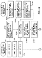
- A device according to claim 13, characterized by further comprising:determining means (405) for determining whether said portable electronic device is driven by said contacting or noncontacting interface (401, 400); andholding means (405) for maintaining the connection between the other interface and said control circuit (405) on the basis of the determination result from said determining means (405).
- A device according to claim 14, characterized in thatsaid connecting means (312 to 316, 317 to 320) selectively connects to said control circuit (405) one of said contacting and noncontacting interfaces (401, 400) by which said portable electronic device is activated, andsaid determining means (405) and said holding means (405) operate when a prestored initialization program is executed upon activation of said portable electronic device.
- A device according to claim 15, characterized by further comprising:storage means (409) for storing the determination result from said determining means (405); andcontrol means (405) for monitoring state signals from said contacting and noncontacting interfaces (401, 400) while said portable electronic device is communicating with a terminal apparatus via said contacting or noncontacting interface (401, 400), checking whether a monitoring result changes from the state signals stored in said storage means (409), and stops the communication with said terminal apparatus if the monitoring result changes.
- A device according to claim 9, said connecting means (312 to 316, 317 to 320) comprising:a switch (312 to 316) arranged between contact terminals of said contacting interface (401) and said control circuit (405) to connect one of said contact and noncontacting interfaces (401, 400) to said control circuit (405).
- A portable electronic device comprising contacting and noncontacting interfaces (401, 400) and a control circuit (405) connected to said contacting and noncontacting interfaces (401, 400), and is driven by said contacting or noncontacting interface (401, 400),
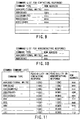
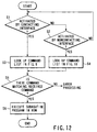
characterized in that said device further comprising:detecting means (405) for detecting whether said portable electronic device is driven via said contacting or noncontacting interface (401, 400); andswitching means (315a) for switching commands executable by said portable electronic device on the basis of the detection result from said detecting means (405). - A device according to claim 18, characterized in that said switching means (315a) permits execution of data rewrite and erase commands if said detecting means (405) detects that said portable electronic device is activated by said contacting interface (401), and inhibits execution of the data rewrite and erase commands if said detecting means (405) detects that said portable electronic device is activated by said noncontacting interface (400).
- A device according to claim 18, characterized by further comprising:a table (407) storing lists of commands executable when said detecting means detects that said portable electronic device is driven by said contacting interface and commands executable when said detecting means (405) detects that said portable electronic device is driven by said noncontacting interface (400),
wherein said switching means (315a) determines on the basis of the detection result from said detecting means (405) whether a command received from an external apparatus can be executed by looking up said table (407).
Priority Applications (2)
| Application Number | Priority Date | Filing Date | Title |
|---|---|---|---|
| EP05018293.0A EP1605388B2 (en) | 1998-03-24 | 1999-03-01 | Portable electronic device with contacting and noncontacting interfaces |
| EP09001333.5A EP2065833B1 (en) | 1998-03-24 | 1999-03-01 | Portable electronic device with contacting and noncontacting interfaces |
Applications Claiming Priority (6)
| Application Number | Priority Date | Filing Date | Title |
|---|---|---|---|
| JP07557498A JP3983885B2 (en) | 1998-03-24 | 1998-03-24 | Compound IC card and IC module for compound IC card |
| JP7569198 | 1998-03-24 | ||
| JP10075691A JPH11272823A (en) | 1998-03-24 | 1998-03-24 | Composite ic card having contact and contactless interface |
| JP7569298 | 1998-03-24 | ||
| JP7557498 | 1998-03-24 | ||
| JP07569298A JP3971020B2 (en) | 1998-03-24 | 1998-03-24 | Compound IC card and IC module for compound IC card |
Related Child Applications (2)
| Application Number | Title | Priority Date | Filing Date |
|---|---|---|---|
| EP05018293.0A Division EP1605388B2 (en) | 1998-03-24 | 1999-03-01 | Portable electronic device with contacting and noncontacting interfaces |
| EP09001333.5A Division EP2065833B1 (en) | 1998-03-24 | 1999-03-01 | Portable electronic device with contacting and noncontacting interfaces |
Publications (3)
| Publication Number | Publication Date |
|---|---|
| EP0945828A2 true EP0945828A2 (en) | 1999-09-29 |
| EP0945828A3 EP0945828A3 (en) | 2000-07-05 |
| EP0945828B1 EP0945828B1 (en) | 2006-11-15 |
Family
ID=27301872
Family Applications (3)
| Application Number | Title | Priority Date | Filing Date |
|---|---|---|---|
| EP09001333.5A Expired - Lifetime EP2065833B1 (en) | 1998-03-24 | 1999-03-01 | Portable electronic device with contacting and noncontacting interfaces |
| EP99103878A Expired - Lifetime EP0945828B1 (en) | 1998-03-24 | 1999-03-01 | IC card with contacting and noncontacting interfaces |
| EP05018293.0A Expired - Lifetime EP1605388B2 (en) | 1998-03-24 | 1999-03-01 | Portable electronic device with contacting and noncontacting interfaces |
Family Applications Before (1)
| Application Number | Title | Priority Date | Filing Date |
|---|---|---|---|
| EP09001333.5A Expired - Lifetime EP2065833B1 (en) | 1998-03-24 | 1999-03-01 | Portable electronic device with contacting and noncontacting interfaces |
Family Applications After (1)
| Application Number | Title | Priority Date | Filing Date |
|---|---|---|---|
| EP05018293.0A Expired - Lifetime EP1605388B2 (en) | 1998-03-24 | 1999-03-01 | Portable electronic device with contacting and noncontacting interfaces |
Country Status (7)
| Country | Link |
|---|---|
| US (1) | US6375082B1 (en) |
| EP (3) | EP2065833B1 (en) |
| KR (1) | KR100357677B1 (en) |
| CN (1) | CN1231459A (en) |
| AT (2) | ATE430340T1 (en) |
| DE (2) | DE69933963T2 (en) |
| TW (1) | TW569143B (en) |
Cited By (18)
| Publication number | Priority date | Publication date | Assignee | Title |
|---|---|---|---|---|
| WO2001084492A1 (en) * | 2000-05-03 | 2001-11-08 | Schlumberger Systemes | Integrated circuit card and case therefor |
| FR2809516A1 (en) * | 2000-05-25 | 2001-11-30 | Innovatron Electronique | System for preventing fraud in money card systems that are charged with monetary units and then used to pay for goods or services by use in a card reader, by preventing use of inductive contacts except when an access code is used |
| EP1179806A2 (en) * | 2000-07-10 | 2002-02-13 | Oki Electric Industry Co. Ltd. | Intergrated circuit card |
| EP1258831A2 (en) * | 2001-05-17 | 2002-11-20 | Matsushita Electric Industrial Co., Ltd. | IC Card and Electronic Devices having contact and non-contact interface |
| EP1313063A2 (en) * | 2001-10-24 | 2003-05-21 | Kabushiki Kaisha Toshiba | Combination contact/contactless IC card |
| EP1441305A1 (en) * | 2001-10-31 | 2004-07-28 | Sony Corporation | Ic card; information processing terminal; trilateral data communication system; and method |
| US6814295B2 (en) | 2000-04-20 | 2004-11-09 | Koninklijke Philips Electronics N.V. | Frequency sensor for each interface of a data carrier |
| EP1493125A1 (en) * | 2002-04-08 | 2005-01-05 | Nokia Corporation | Mobile terminal featuring smart card interrupt |
| EP1496468A1 (en) * | 2003-07-11 | 2005-01-12 | Axalto S.A. | Procedure for the memory management in a portable carrier capable for mixed-type connections |
| SG108922A1 (en) * | 2002-05-23 | 2005-02-28 | Sharp Kk | Combination-type ic card |
| EP1569164A2 (en) | 2004-02-24 | 2005-08-31 | Sony Corporation | Semiconductor integrated circuit, mobile module, and message communication method |
| EP1630727A2 (en) * | 2004-08-26 | 2006-03-01 | Samsung Electronics Co., Ltd. | Multi-interface card and a method of handling requests in such a card |
| FR2888976A1 (en) * | 2005-07-25 | 2007-01-26 | Oberthur Card Syst Sa | ELECTRONIC ENTITY WITH CONTACT AND REMOTE COMMUNICATION MEANS |
| FR2897704A1 (en) * | 2006-02-20 | 2007-08-24 | Gemplus Sa | Detachable electronic device e.g. combi-chip, for e.g. portable telephone, has control unit transmitting activation signal based on detection of activation data for passing selection unit from one selection position to another position |
| EP2100281A1 (en) * | 2006-12-07 | 2009-09-16 | Neology, Inc. | Systems and methods for incorporating an rfid circuit into a memory device |
| WO2011047915A1 (en) * | 2009-10-21 | 2011-04-28 | G. Holdings Ltd | Portable electronic device and method for alternate data conveyance operations responsive to an invariable activation command |
| EP2693368A1 (en) * | 2011-03-31 | 2014-02-05 | Panasonic Corporation | Rfid device, host, apparatus with rfid device mounted thereon, and method of controlling rfid device |
| US10185952B2 (en) | 2009-06-05 | 2019-01-22 | Visa International Service Association | Contactless enablement of device |
Families Citing this family (36)
| Publication number | Priority date | Publication date | Assignee | Title |
|---|---|---|---|---|
| US6955300B1 (en) * | 1999-06-29 | 2005-10-18 | Renesas Technology Corp. | Dual interface IC card |
| DE19929766C1 (en) * | 1999-06-29 | 2001-03-22 | Wacker Werke Kg | Nameplate with storage device |
| JP3461308B2 (en) * | 1999-07-30 | 2003-10-27 | Necマイクロシステム株式会社 | Data processing device and operation control method thereof |
| JP3349998B2 (en) | 1999-09-07 | 2002-11-25 | エヌイーシーマイクロシステム株式会社 | Data processing device and operation control method thereof |
| JP4341127B2 (en) * | 1999-12-20 | 2009-10-07 | ソニー株式会社 | Information processing device, IC card and reader / writer |
| DE10006816C2 (en) * | 2000-02-15 | 2003-03-13 | Sokymat Id Component Gmbh | Transponder device for the identification of objects in relation to facilities |
| US7000834B2 (en) * | 2001-02-21 | 2006-02-21 | International Business Machines Corporation | Method to address security and privacy issue of the use of RFID systems to track consumer products |
| FR2822272B1 (en) * | 2001-03-13 | 2003-06-27 | St Microelectronics Sa | CONTACTLESS CHIP CARD WITH OPERATING SYSTEM USED IN CONTACT CARDS AND READER OF SUCH CONTACTLESS CARDS |
| ATE368351T1 (en) * | 2001-05-14 | 2007-08-15 | Innovision Res & Tech Plc | PORTABLE COMMUNICATIONS DEVICE FOR USE IN A SALES SYSTEM |
| JP3617491B2 (en) * | 2001-10-31 | 2005-02-02 | ソニー株式会社 | IC chip and information processing terminal |
| JP3664152B2 (en) * | 2002-06-06 | 2005-06-22 | ソニー株式会社 | Electron gun for cathode ray tube and display device |
| JP3958243B2 (en) | 2003-04-14 | 2007-08-15 | 松下電器産業株式会社 | IC card and its OS startup method |
| JP3972304B2 (en) * | 2003-04-15 | 2007-09-05 | ソニー株式会社 | Wireless communication system and method, wireless communication apparatus and method, and program |
| US6935797B2 (en) * | 2003-08-12 | 2005-08-30 | Creative Technology Limited | Keyboard with built-in microphone |
| KR100560768B1 (en) * | 2003-09-05 | 2006-03-13 | 삼성전자주식회사 | Dual interface integrated circuit card |
| KR101053185B1 (en) * | 2005-02-24 | 2011-08-01 | 삼성전자주식회사 | Smart card and its mixed mode control method |
| JP2007257542A (en) * | 2006-03-24 | 2007-10-04 | Toshiba Corp | Composite portable electronic device and composite ic card |
| US7832647B2 (en) * | 2006-06-30 | 2010-11-16 | Semiconductor Energy Laboratory Co., Ltd. | Semiconductor device |
| US7775442B2 (en) * | 2006-07-12 | 2010-08-17 | Nokia Corporation | Method for accessing after-operation information of secure element applications |
| JP2008059246A (en) * | 2006-08-31 | 2008-03-13 | Yoshikawa Rf System Kk | Data carrier and data carrier system |
| JP2008135003A (en) * | 2006-10-31 | 2008-06-12 | Yoshikawa Rf System Kk | Data carrier and data carrier system |
| JP2008134735A (en) * | 2006-11-27 | 2008-06-12 | Yoshikawa Rf System Kk | Data carrier and data carrier system |
| US8002193B2 (en) * | 2007-03-12 | 2011-08-23 | Visa U.S.A. Inc. | Payment card dynamically receiving power from external source |
| ITMI20071085A1 (en) | 2007-05-28 | 2008-11-29 | Incard Sa | INTEGRATED CIRCUIT CARD INCLUDING A MAIN DEVICE AND AN ADDITIONAL DEVICE. |
| JP4468434B2 (en) * | 2007-12-21 | 2010-05-26 | フェリカネットワークス株式会社 | Communication device, non-contact IC card, signal selection method, and program |
| WO2009119079A1 (en) * | 2008-03-25 | 2009-10-01 | パナソニック株式会社 | Data encryption device |
| JP4640451B2 (en) * | 2008-06-06 | 2011-03-02 | ソニー株式会社 | Contact / non-contact composite IC card, communication method, program, and communication system |
| JP5253003B2 (en) * | 2008-06-09 | 2013-07-31 | キヤノン株式会社 | COMMUNICATION CONTROL DEVICE AND ITS CONTROL METHOD |
| CN102171811B (en) * | 2008-10-03 | 2014-01-01 | 株式会社半导体能源研究所 | Semiconductor device |
| JP5347813B2 (en) * | 2009-08-03 | 2013-11-20 | ソニー株式会社 | Communication apparatus and communication method |
| US8313028B2 (en) | 2010-02-17 | 2012-11-20 | On Track Innovations Ltd. | Multiple antenna reading system suitable for use with contactless transaction devices |
| CN101814910A (en) * | 2010-04-30 | 2010-08-25 | 王佑夫 | Control method of non-contact intelligent key switch and system thereof |
| US8195236B2 (en) | 2010-06-16 | 2012-06-05 | On Track Innovations Ltd. | Retrofit contactless smart SIM functionality in mobile communicators |
| US8424757B2 (en) | 2010-12-06 | 2013-04-23 | On Track Innovations Ltd. | Contactless smart SIM functionality retrofit for mobile communication device |
| KR101939237B1 (en) * | 2011-06-14 | 2019-01-17 | 삼성전자 주식회사 | Internal voltage generating circuit and smart card |
| US9921739B2 (en) * | 2014-03-03 | 2018-03-20 | Microchip Technology Incorporated | System and method for gesture control |
Citations (3)
| Publication number | Priority date | Publication date | Assignee | Title |
|---|---|---|---|---|
| EP0424726A1 (en) * | 1989-10-24 | 1991-05-02 | Angewandte Digital Elektronik GmbH | Chipcard |
| WO1996038814A2 (en) * | 1995-06-02 | 1996-12-05 | Philips Electronics N.V. | Chip-card |
| DE19531372A1 (en) * | 1995-08-25 | 1997-02-27 | Siemens Ag | Smart card |
Family Cites Families (23)
| Publication number | Priority date | Publication date | Assignee | Title |
|---|---|---|---|---|
| JPS61143890A (en) * | 1984-12-18 | 1986-07-01 | Toshiba Corp | Portable card |
| JPH0691526B2 (en) * | 1985-03-08 | 1994-11-14 | 株式会社東芝 | Communications system |
| JPH0416831A (en) | 1990-05-11 | 1992-01-21 | Nec Corp | Production of nonlinear optical element |
| US5241160A (en) * | 1990-12-28 | 1993-08-31 | On Track Innovations Ltd. | System and method for the non-contact transmission of data |
| JPH07117385A (en) * | 1993-09-01 | 1995-05-09 | Toshiba Corp | Thin ic card and manufacture thereof |
| DE4403753C1 (en) * | 1994-02-08 | 1995-07-20 | Angewandte Digital Elektronik | Combined chip card |
| DE4406704C1 (en) * | 1994-03-02 | 1995-07-20 | Angewandte Digital Elektronik | Smart card |
| JPH07271939A (en) * | 1994-03-30 | 1995-10-20 | Mitsubishi Denki Semiconductor Software Kk | Non-contact ic card, card reader/writer and card device |
| DE19509517C1 (en) * | 1995-03-20 | 1996-10-10 | Angewandte Digital Elektronik | Device consisting of at least one card terminal for transmitting energy to a chip card and for exchanging data with the chip card via electromagnetic waves |
| JP3519491B2 (en) * | 1995-03-31 | 2004-04-12 | 株式会社東海理化電機製作所 | IC card |
| KR970017039A (en) * | 1995-09-29 | 1997-04-28 | 장세탁 | Interface device for contact / contactless card and its control method |
| KR970049838A (en) * | 1995-12-27 | 1997-07-29 | 김광호 | Composite i-seed card |
| DE19604045A1 (en) * | 1996-02-05 | 1997-08-07 | Siemens Ag | Device for processing and storing data |
| JP3360002B2 (en) * | 1996-03-14 | 2002-12-24 | 沖電気工業株式会社 | Contact / non-contact IC card and contact / non-contact IC card reader / writer |
| US5834756A (en) * | 1996-06-03 | 1998-11-10 | Motorola, Inc. | Magnetically communicative card |
| JPH09326021A (en) | 1996-06-05 | 1997-12-16 | Dainippon Printing Co Ltd | Composite ic card |
| FR2752076B1 (en) * | 1996-08-05 | 1998-09-11 | Inside Technologies | ELECTRICAL SUPPLY SYSTEM FOR MICROCIRCUIT WITH MIXED OPERATION, WITH OR WITHOUT CONTACT |
| IL119943A (en) * | 1996-12-31 | 2000-11-21 | On Track Innovations Ltd | Contact/contactless data transaction card |
| GB2321744B (en) * | 1997-01-30 | 2000-05-17 | Motorola Inc | Portable data carrier and method for selecting operating mode thereof |
| JP3528899B2 (en) * | 1997-05-22 | 2004-05-24 | 日本電信電話株式会社 | Hybrid IC card |
| JP4031084B2 (en) * | 1997-07-04 | 2008-01-09 | 株式会社東芝 | IC card |
| ATE404939T1 (en) * | 1997-09-23 | 2008-08-15 | Nxp Bv | HYBRID DATA CARRIER AND CIRCUIT WITH POTENTIAL EQUALIZATION DEVICE FOR EQUALIZING THE POTENTIAL ON AT LEAST TWO CONTACT ELEMENTS |
| IL122841A0 (en) * | 1997-12-31 | 1998-08-16 | On Track Innovations Ltd | Smart card for effecting data transfer using multiple protocols |
-
1999
- 1999-03-01 DE DE69933963T patent/DE69933963T2/en not_active Expired - Lifetime
- 1999-03-01 AT AT05018293T patent/ATE430340T1/en not_active IP Right Cessation
- 1999-03-01 AT AT99103878T patent/ATE345539T1/en not_active IP Right Cessation
- 1999-03-01 EP EP09001333.5A patent/EP2065833B1/en not_active Expired - Lifetime
- 1999-03-01 EP EP99103878A patent/EP0945828B1/en not_active Expired - Lifetime
- 1999-03-01 DE DE69940834T patent/DE69940834D1/en not_active Expired - Lifetime
- 1999-03-01 EP EP05018293.0A patent/EP1605388B2/en not_active Expired - Lifetime
- 1999-03-08 US US09/263,955 patent/US6375082B1/en not_active Expired - Lifetime
- 1999-03-08 TW TW088103525A patent/TW569143B/en not_active IP Right Cessation
- 1999-03-23 KR KR1019990009917A patent/KR100357677B1/en not_active IP Right Cessation
- 1999-03-24 CN CN99104405A patent/CN1231459A/en active Pending
Patent Citations (3)
| Publication number | Priority date | Publication date | Assignee | Title |
|---|---|---|---|---|
| EP0424726A1 (en) * | 1989-10-24 | 1991-05-02 | Angewandte Digital Elektronik GmbH | Chipcard |
| WO1996038814A2 (en) * | 1995-06-02 | 1996-12-05 | Philips Electronics N.V. | Chip-card |
| DE19531372A1 (en) * | 1995-08-25 | 1997-02-27 | Siemens Ag | Smart card |
Cited By (43)
| Publication number | Priority date | Publication date | Assignee | Title |
|---|---|---|---|---|
| US6814295B2 (en) | 2000-04-20 | 2004-11-09 | Koninklijke Philips Electronics N.V. | Frequency sensor for each interface of a data carrier |
| WO2001084492A1 (en) * | 2000-05-03 | 2001-11-08 | Schlumberger Systemes | Integrated circuit card and case therefor |
| FR2809516A1 (en) * | 2000-05-25 | 2001-11-30 | Innovatron Electronique | System for preventing fraud in money card systems that are charged with monetary units and then used to pay for goods or services by use in a card reader, by preventing use of inductive contacts except when an access code is used |
| EP1179806A2 (en) * | 2000-07-10 | 2002-02-13 | Oki Electric Industry Co. Ltd. | Intergrated circuit card |
| EP1179806A3 (en) * | 2000-07-10 | 2002-09-25 | Oki Electric Industry Co. Ltd. | Intergrated circuit card |
| US6899277B2 (en) | 2001-05-17 | 2005-05-31 | Matsushita Electric Industrial Co., Ltd. | IC card and electronic devices |
| EP1258831A2 (en) * | 2001-05-17 | 2002-11-20 | Matsushita Electric Industrial Co., Ltd. | IC Card and Electronic Devices having contact and non-contact interface |
| EP1258831A3 (en) * | 2001-05-17 | 2003-06-11 | Matsushita Electric Industrial Co., Ltd. | IC Card and Electronic Devices having contact and non-contact interface |
| EP1313063A2 (en) * | 2001-10-24 | 2003-05-21 | Kabushiki Kaisha Toshiba | Combination contact/contactless IC card |
| EP1313063A3 (en) * | 2001-10-24 | 2003-08-20 | Kabushiki Kaisha Toshiba | Combination contact/contactless IC card |
| EP1441305A1 (en) * | 2001-10-31 | 2004-07-28 | Sony Corporation | Ic card; information processing terminal; trilateral data communication system; and method |
| EP1441305A4 (en) * | 2001-10-31 | 2005-08-24 | Sony Corp | Ic card; information processing terminal; trilateral data communication system; and method |
| US7188777B2 (en) | 2001-10-31 | 2007-03-13 | Sony Corporation | IC card, information processing terminal, trilateral data communication system, and method |
| US7344074B2 (en) | 2002-04-08 | 2008-03-18 | Nokia Corporation | Mobile terminal featuring smart card interrupt |
| EP1493125A4 (en) * | 2002-04-08 | 2007-12-26 | Nokia Corp | Mobile terminal featuring smart card interrupt |
| EP1493125A1 (en) * | 2002-04-08 | 2005-01-05 | Nokia Corporation | Mobile terminal featuring smart card interrupt |
| SG108922A1 (en) * | 2002-05-23 | 2005-02-28 | Sharp Kk | Combination-type ic card |
| US7178737B2 (en) | 2002-05-23 | 2007-02-20 | Sharp Kabushiki Kaisha | Combination-type IC card |
| US9022294B2 (en) | 2003-04-14 | 2015-05-05 | G. Holdings Ltd. | Portable electronic device and method for alternate data conveyance operations responsive to an invariable activation command |
| WO2005006245A1 (en) | 2003-07-11 | 2005-01-20 | Axalto Sa | Memory management method for a multimode portable object |
| EP1496468A1 (en) * | 2003-07-11 | 2005-01-12 | Axalto S.A. | Procedure for the memory management in a portable carrier capable for mixed-type connections |
| EP1569164A2 (en) | 2004-02-24 | 2005-08-31 | Sony Corporation | Semiconductor integrated circuit, mobile module, and message communication method |
| EP1569164A3 (en) * | 2004-02-24 | 2008-05-14 | Sony Corporation | Semiconductor integrated circuit, mobile module, and message communication method |
| US7365642B2 (en) | 2004-02-24 | 2008-04-29 | Sony Corporation | Semiconductor integrated circuit, mobile module, and message communication method |
| EP1630727A3 (en) * | 2004-08-26 | 2006-04-05 | Samsung Electronics Co., Ltd. | Multi-interface card and a method of handling requests in such a card |
| EP1630727A2 (en) * | 2004-08-26 | 2006-03-01 | Samsung Electronics Co., Ltd. | Multi-interface card and a method of handling requests in such a card |
| US7520438B2 (en) | 2004-08-26 | 2009-04-21 | Samsung Electronics, Co., Ltd. | Method of multi-interfacing between smart card and memory card, and multi-interface card |
| WO2007012738A1 (en) * | 2005-07-25 | 2007-02-01 | Oberthur Card Systems Sa | Electronic entity with contact and remote communication means |
| FR2888976A1 (en) * | 2005-07-25 | 2007-01-26 | Oberthur Card Syst Sa | ELECTRONIC ENTITY WITH CONTACT AND REMOTE COMMUNICATION MEANS |
| US9600697B2 (en) | 2005-07-25 | 2017-03-21 | Oberthur Technologies | Electronic entity with contact and remote communication means |
| US9111188B2 (en) | 2005-07-25 | 2015-08-18 | Oberthur Technologies | Electronic entity with contact and remote communication means |
| EP2490159A1 (en) * | 2005-07-25 | 2012-08-22 | Oberthur Card Systems Sa | Electronic entity with a means for communication by contact and remotely |
| KR101156298B1 (en) * | 2005-07-25 | 2012-06-13 | 오베르뛰르 테크놀로지스 | Electornic entity with contact and remote communication means |
| WO2007096366A1 (en) * | 2006-02-20 | 2007-08-30 | Gemplus | Removable multiple-access electronic device and corresponding external communication device |
| FR2897704A1 (en) * | 2006-02-20 | 2007-08-24 | Gemplus Sa | Detachable electronic device e.g. combi-chip, for e.g. portable telephone, has control unit transmitting activation signal based on detection of activation data for passing selection unit from one selection position to another position |
| EP2100281A4 (en) * | 2006-12-07 | 2011-05-11 | Neology Inc | Systems and methods for incorporating an rfid circuit into a memory device |
| EP2100281A1 (en) * | 2006-12-07 | 2009-09-16 | Neology, Inc. | Systems and methods for incorporating an rfid circuit into a memory device |
| US10185952B2 (en) | 2009-06-05 | 2019-01-22 | Visa International Service Association | Contactless enablement of device |
| US11062298B2 (en) | 2009-06-05 | 2021-07-13 | Visa International Service Association | Contactless enablement and disablement |
| WO2011047915A1 (en) * | 2009-10-21 | 2011-04-28 | G. Holdings Ltd | Portable electronic device and method for alternate data conveyance operations responsive to an invariable activation command |
| EP2693368A1 (en) * | 2011-03-31 | 2014-02-05 | Panasonic Corporation | Rfid device, host, apparatus with rfid device mounted thereon, and method of controlling rfid device |
| EP2693368A4 (en) * | 2011-03-31 | 2014-06-11 | Panasonic Corp | Rfid device, host, apparatus with rfid device mounted thereon, and method of controlling rfid device |
| US9141904B2 (en) | 2011-03-31 | 2015-09-22 | Panasonic Intellectual Property Corporation Of America | RFID device, host, RFID-embedded apparatus, and method of controlling RFID device |
Also Published As
| Publication number | Publication date |
|---|---|
| ATE345539T1 (en) | 2006-12-15 |
| DE69940834D1 (en) | 2009-06-10 |
| ATE430340T1 (en) | 2009-05-15 |
| DE69933963D1 (en) | 2006-12-28 |
| EP0945828B1 (en) | 2006-11-15 |
| EP1605388A2 (en) | 2005-12-14 |
| TW569143B (en) | 2004-01-01 |
| US6375082B1 (en) | 2002-04-23 |
| EP2065833B1 (en) | 2015-12-23 |
| EP0945828A3 (en) | 2000-07-05 |
| EP2065833A1 (en) | 2009-06-03 |
| EP1605388A3 (en) | 2005-12-21 |
| KR19990078167A (en) | 1999-10-25 |
| EP1605388B2 (en) | 2016-09-14 |
| DE69933963T2 (en) | 2007-09-20 |
| EP1605388B1 (en) | 2009-04-29 |
| KR100357677B1 (en) | 2002-10-18 |
| CN1231459A (en) | 1999-10-13 |
Similar Documents
| Publication | Publication Date | Title |
|---|---|---|
| EP2065833B1 (en) | Portable electronic device with contacting and noncontacting interfaces | |
| CN100581066C (en) | Radio tag and radio tag communication distance modification method | |
| US6564995B1 (en) | Smart card application-selection | |
| JP4337645B2 (en) | IC tag module, electronic device, information communication system, and IC tag module communication control method | |
| AU2015302187B2 (en) | Payment card having light-emitting diode indicators coordinated with stored payment applications | |
| JP3971020B2 (en) | Compound IC card and IC module for compound IC card | |
| EP3236405B1 (en) | Selecting an application on a card | |
| JP2001155120A (en) | Portable terminal with rfid reader/writer | |
| JP2006120178A (en) | Composite ic card | |
| JP4550860B2 (en) | Compound IC card and IC module for compound IC card | |
| US20120234926A1 (en) | Portable electronic apparatus | |
| JP2007087168A (en) | Composite portable electronic device and composite ic card | |
| JP3983885B2 (en) | Compound IC card and IC module for compound IC card | |
| JPH11272823A (en) | Composite ic card having contact and contactless interface | |
| JP3881683B2 (en) | Compound IC card | |
| JP2009080850A (en) | Composite ic card | |
| JP7366765B2 (en) | Control program for IC cards, IC card processing systems, and IC card processing devices | |
| JP3701571B2 (en) | Integrated circuit and IC card | |
| JP2011141904A (en) | Composite ic card and ic module for the composite ic card | |
| JP3243591B2 (en) | Contactless data carrier | |
| JP7468598B1 (en) | Electronic information storage medium, IC chip, non-contact IC card, processing method, and program | |
| KR20070022557A (en) | Smart Card Leader System for using and processing of diverse type of Smart Card | |
| JP4417705B2 (en) | Portable information storage medium, its holder and portable information storage medium program | |
| JP3586848B2 (en) | Contactless data carrier | |
| JP4355247B2 (en) | IC card device with communication function |
Legal Events
| Date | Code | Title | Description |
|---|---|---|---|
| PUAI | Public reference made under article 153(3) epc to a published international application that has entered the european phase |
Free format text: ORIGINAL CODE: 0009012 |
|
| 17P | Request for examination filed |
Effective date: 19990301 |
|
| AK | Designated contracting states |
Kind code of ref document: A2 Designated state(s): AT DE FR GB |
|
| AX | Request for extension of the european patent |
Free format text: AL;LT;LV;MK;RO;SI |
|
| PUAL | Search report despatched |
Free format text: ORIGINAL CODE: 0009013 |
|
| AK | Designated contracting states |
Kind code of ref document: A3 Designated state(s): AT BE CH CY DE DK ES FI FR GB GR IE IT LI LU MC NL PT SE |
|
| AX | Request for extension of the european patent |
Free format text: AL;LT;LV;MK;RO;SI |
|
| RIC1 | Information provided on ipc code assigned before grant |
Free format text: 7G 06K 7/00 A, 7G 06K 19/077 B, 7G 06K 19/07 B |
|
| AKX | Designation fees paid |
Free format text: AT DE FR GB |
|
| 17Q | First examination report despatched |
Effective date: 20050211 |
|
| RAP1 | Party data changed (applicant data changed or rights of an application transferred) |
Owner name: KABUSHIKI KAISHA TOSHIBA |
|
| RIN1 | Information on inventor provided before grant (corrected) |
Inventor name: FUKUDA, AKIC/O TOSHIBA KABUSHIKI KAISHA Inventor name: NAKANO, HIROOC/O TOSHIBA KABUSHIKI KAISHA Inventor name: MUKUGE, MASATSUGUC/O TOSHIBA KABUSHIKI KAISHA Inventor name: KOBAYASHI, TSUTOMU C/O TOSHIBA KABUSHIKI KAISHA |
|
| GRAP | Despatch of communication of intention to grant a patent |
Free format text: ORIGINAL CODE: EPIDOSNIGR1 |
|
| RTI1 | Title (correction) |
Free format text: IC CARD WITH CONTACTING AND NONCONTACTING INTERFACES |
|
| GRAS | Grant fee paid |
Free format text: ORIGINAL CODE: EPIDOSNIGR3 |
|
| GRAA | (expected) grant |
Free format text: ORIGINAL CODE: 0009210 |
|
| AK | Designated contracting states |
Kind code of ref document: B1 Designated state(s): AT DE FR GB |
|
| PG25 | Lapsed in a contracting state [announced via postgrant information from national office to epo] |
Ref country code: AT Free format text: LAPSE BECAUSE OF FAILURE TO SUBMIT A TRANSLATION OF THE DESCRIPTION OR TO PAY THE FEE WITHIN THE PRESCRIBED TIME-LIMIT Effective date: 20061115 |
|
| REG | Reference to a national code |
Ref country code: GB Ref legal event code: FG4D |
|
| REF | Corresponds to: |
Ref document number: 69933963 Country of ref document: DE Date of ref document: 20061228 Kind code of ref document: P |
|
| ET | Fr: translation filed | ||
| PLBE | No opposition filed within time limit |
Free format text: ORIGINAL CODE: 0009261 |
|
| STAA | Information on the status of an ep patent application or granted ep patent |
Free format text: STATUS: NO OPPOSITION FILED WITHIN TIME LIMIT |
|
| 26N | No opposition filed |
Effective date: 20070817 |
|
| PGFP | Annual fee paid to national office [announced via postgrant information from national office to epo] |
Ref country code: GB Payment date: 20140226 Year of fee payment: 16 |
|
| GBPC | Gb: european patent ceased through non-payment of renewal fee |
Effective date: 20150301 |
|
| PG25 | Lapsed in a contracting state [announced via postgrant information from national office to epo] |
Ref country code: GB Free format text: LAPSE BECAUSE OF NON-PAYMENT OF DUE FEES Effective date: 20150301 |
|
| REG | Reference to a national code |
Ref country code: FR Ref legal event code: PLFP Year of fee payment: 18 |
|
| REG | Reference to a national code |
Ref country code: FR Ref legal event code: PLFP Year of fee payment: 19 |
|
| REG | Reference to a national code |
Ref country code: FR Ref legal event code: PLFP Year of fee payment: 20 |
|
| PGFP | Annual fee paid to national office [announced via postgrant information from national office to epo] |
Ref country code: DE Payment date: 20180214 Year of fee payment: 20 |
|
| PGFP | Annual fee paid to national office [announced via postgrant information from national office to epo] |
Ref country code: FR Payment date: 20180111 Year of fee payment: 20 |
|
| REG | Reference to a national code |
Ref country code: DE Ref legal event code: R071 Ref document number: 69933963 Country of ref document: DE |