EP0948181A2 - Method for creating and modifying similar and dissimilar databases for use in operator services configurations for telecommunication system - Google Patents
Method for creating and modifying similar and dissimilar databases for use in operator services configurations for telecommunication system Download PDFInfo
- Publication number
- EP0948181A2 EP0948181A2 EP99302439A EP99302439A EP0948181A2 EP 0948181 A2 EP0948181 A2 EP 0948181A2 EP 99302439 A EP99302439 A EP 99302439A EP 99302439 A EP99302439 A EP 99302439A EP 0948181 A2 EP0948181 A2 EP 0948181A2
- Authority
- EP
- European Patent Office
- Prior art keywords
- operator services
- database
- data
- configuring
- new
- Prior art date
- Legal status (The legal status is an assumption and is not a legal conclusion. Google has not performed a legal analysis and makes no representation as to the accuracy of the status listed.)
- Granted
Links
Images


Classifications
-
- H—ELECTRICITY
- H04—ELECTRIC COMMUNICATION TECHNIQUE
- H04M—TELEPHONIC COMMUNICATION
- H04M3/00—Automatic or semi-automatic exchanges
- H04M3/42—Systems providing special services or facilities to subscribers
- H04M3/42136—Administration or customisation of services
- H04M3/42144—Administration or customisation of services by service provider
-
- H—ELECTRICITY
- H04—ELECTRIC COMMUNICATION TECHNIQUE
- H04Q—SELECTING
- H04Q3/00—Selecting arrangements
- H04Q3/42—Circuit arrangements for indirect selecting controlled by common circuits, e.g. register controller, marker
- H04Q3/54—Circuit arrangements for indirect selecting controlled by common circuits, e.g. register controller, marker in which the logic circuitry controlling the exchange is centralised
- H04Q3/545—Circuit arrangements for indirect selecting controlled by common circuits, e.g. register controller, marker in which the logic circuitry controlling the exchange is centralised using a stored programme
- H04Q3/54508—Configuration, initialisation
- H04Q3/54533—Configuration data, translation, passwords, databases
-
- H—ELECTRICITY
- H04—ELECTRIC COMMUNICATION TECHNIQUE
- H04M—TELEPHONIC COMMUNICATION
- H04M2203/00—Aspects of automatic or semi-automatic exchanges
- H04M2203/55—Aspects of automatic or semi-automatic exchanges related to network data storage and management
- H04M2203/558—Databases
-
- Y—GENERAL TAGGING OF NEW TECHNOLOGICAL DEVELOPMENTS; GENERAL TAGGING OF CROSS-SECTIONAL TECHNOLOGIES SPANNING OVER SEVERAL SECTIONS OF THE IPC; TECHNICAL SUBJECTS COVERED BY FORMER USPC CROSS-REFERENCE ART COLLECTIONS [XRACs] AND DIGESTS
- Y10—TECHNICAL SUBJECTS COVERED BY FORMER USPC
- Y10S—TECHNICAL SUBJECTS COVERED BY FORMER USPC CROSS-REFERENCE ART COLLECTIONS [XRACs] AND DIGESTS
- Y10S707/00—Data processing: database and file management or data structures
- Y10S707/99931—Database or file accessing
- Y10S707/99933—Query processing, i.e. searching
-
- Y—GENERAL TAGGING OF NEW TECHNOLOGICAL DEVELOPMENTS; GENERAL TAGGING OF CROSS-SECTIONAL TECHNOLOGIES SPANNING OVER SEVERAL SECTIONS OF THE IPC; TECHNICAL SUBJECTS COVERED BY FORMER USPC CROSS-REFERENCE ART COLLECTIONS [XRACs] AND DIGESTS
- Y10—TECHNICAL SUBJECTS COVERED BY FORMER USPC
- Y10S—TECHNICAL SUBJECTS COVERED BY FORMER USPC CROSS-REFERENCE ART COLLECTIONS [XRACs] AND DIGESTS
- Y10S707/00—Data processing: database and file management or data structures
- Y10S707/99941—Database schema or data structure
- Y10S707/99944—Object-oriented database structure
- Y10S707/99945—Object-oriented database structure processing
-
- Y—GENERAL TAGGING OF NEW TECHNOLOGICAL DEVELOPMENTS; GENERAL TAGGING OF CROSS-SECTIONAL TECHNOLOGIES SPANNING OVER SEVERAL SECTIONS OF THE IPC; TECHNICAL SUBJECTS COVERED BY FORMER USPC CROSS-REFERENCE ART COLLECTIONS [XRACs] AND DIGESTS
- Y10—TECHNICAL SUBJECTS COVERED BY FORMER USPC
- Y10S—TECHNICAL SUBJECTS COVERED BY FORMER USPC CROSS-REFERENCE ART COLLECTIONS [XRACs] AND DIGESTS
- Y10S707/00—Data processing: database and file management or data structures
- Y10S707/99941—Database schema or data structure
- Y10S707/99948—Application of database or data structure, e.g. distributed, multimedia, or image
-
- Y—GENERAL TAGGING OF NEW TECHNOLOGICAL DEVELOPMENTS; GENERAL TAGGING OF CROSS-SECTIONAL TECHNOLOGIES SPANNING OVER SEVERAL SECTIONS OF THE IPC; TECHNICAL SUBJECTS COVERED BY FORMER USPC CROSS-REFERENCE ART COLLECTIONS [XRACs] AND DIGESTS
- Y10—TECHNICAL SUBJECTS COVERED BY FORMER USPC
- Y10S—TECHNICAL SUBJECTS COVERED BY FORMER USPC CROSS-REFERENCE ART COLLECTIONS [XRACs] AND DIGESTS
- Y10S707/00—Data processing: database and file management or data structures
- Y10S707/99951—File or database maintenance
- Y10S707/99952—Coherency, e.g. same view to multiple users
- Y10S707/99953—Recoverability
Definitions
- This invention relates to a computer program that can create new operator services databases from all or parts of one or more existing operator services databases containing data information for the operation of data and voice audio telecommunication switches.
- the configuration of telecommunication switches usually occurs in at least three environments.
- Second, when a switch is sold to a customer, the switch is configured to the customer s specifications.
- the configuration of telecommunication switches during these three environments requires the manual input of thousands and possibly millions of records of information. This process is extremely time consuming and can take weeks or months to complete.
- telecommunication companies In the first environment, telecommunication companies continually test new versions of switch software, peripheral devices and other hardware devices during the life of a telecommunication switch.
- switch engineers design different operating environments to establish operating parameters of the new software or hardware.
- Data engineers manually input data to configure the operation of the switch for the designed test.
- the configuration of the testing environment is performed on a data build machine (computer).
- the configuration of the switch to simulate the desired testing operational conditions often involves retesting archived configurations or modified archived configurations. Otherwise, the testing configuration is accomplished by manual data entry.
- the configurations for new switches are manually built new data configurations without relying on existing database configurations.
- the configuration of the features, switching software and hardware is often adopted from other existing configurations.
- the third operational environment is recovery of the switch after the switch has experienced a failure. These failures can result from equipment failure to natural disasters such as earthquakes, hurricanes or fires. Recovery of the failed switch sometimes requires the installation of an emergency backup switch.
- the emergency backup switch requires database configurations that replicate the databases in the damaged switch. Normally, the configuration of the emergency backup switch requires manual, time consuming input of data that will support specific customer features and routing of calls on the emergency backup switch. Having the ability to configure the telecommunication switch by transferring existing data information from known databases into new databases by automating the manual tasks of data entry would save considerable time, money and significantly improve productivity. In addition, instant access to many different switching systems is a critical task that currently requires many hours or days of research and manual browsing. A need exists for a robust process to automatically replace the current manual method data entry to configure operator services data for telecommunications switches.
- the computer program ofthis invention establishes a new database structure and mines source databases to load source operator services data into the new operator services database structure.
- the computer program is capable of searching for the desired data and automates many of the tasks for configuring a new operator services database from the source databases. This eliminates the current requirement for manual data entry for configuring new operator services databases for telecommunication switches.
- This computer program is multifunctional allowing for the browsing of all operator services databases prior to the configuration. Once the target operator services databases are determined, the computer program creates a new data directory structure and selectively copies all or part of the data from the source operator services databases into the new database.
- the invention selects the source databases, determines whether the operator services database supports European Transmission Standard Interface (ETSI), Alternate Mark Inversion (AMI), or both and modifies the equipment numbers and network addresses.
- the program removes the operator services positioning system (OSPS) equipment or network addresses for digital subscriber line (DSL) assignments, transmission control protocol/ Internet protocol (TCP/IP) DSL equipment, IP addresses to ports information, IP access numbers and ETSI ISDN/OSPS numbers.
- the program modifies the equipment and network addresses with the new data relating to the new location of the equipment numbers and addresses.
- the computer program performs a series of queries regarding the OSPS configuration and extracts the data. The data is evolved to the same software release if needed, and loaded into the new OSPS data directory structure.
- This invention provides accurate and timely customer information, significantly decreases the time interval for engineering a new operator services database, decreases the research and data entry time, decreases the interval for lab planning and project management, improves database integrity, provides a cleaner operator services database, reuses existing operator services data eliminating double data entry, reuses some existing software code, use preexisting tools, and provides a platform for future growth and expandability.
- the telecommunication switch manufacturer or telecommunication switch operator saves time, money and decreases time-to-market product and service schedules.
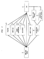
- Figure 1 is a functional flow chart illustrating the logical operations of the main menu of the computer program.
- FIG. 2 illustrates the various hardware components and database types used in conjunction with the computer program.
- Figure 3 illustrates the operation of the computer program as it builds a new database from parts of other databases.
- Figure 4 is a flow chart of the overall features exercised in the operation of the computer program.
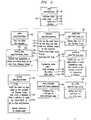
- Figure 5 is a flow chart of the logical operation of the computer program.
- Figure 6 is a flow chart of the browse feature of the computer program.
- Figure 7 is a flow chart of the dialing plan feature configuration of the computer program.
- Figure 8 is a flow chart of the build database feature configuration of the computer program.
- Figure 9 is a flow chart of the build database feature of the computer program.
- Figure 10 is a flow chart of the operator services feature configuration of the computer program.
- Figure 11 is a flow chart of the operator services feature configuration of the computer program.
- Figure 12 is a flow chart of the operator services feature configuration of the computer program.
- Figure 1 illustrates the logical operation of the main menu of the user interface for the Simple Environment Engineering System (ASEES@) computer program. If the SEES program is wrongly selected as the application of choice by the user, the main menu display 10 allows the user to exit 11 the computer program without choosing any ofthe functions. If SEES is selected as the program of choice by the user, from the main menu display 10, the user can choose seven operations.
- ASEES@ Simple Environment Engineering System
- Peripheral interface data bus (PIDB)/ peripheral interface control bus (PICB) 13 allows a user to examine the peripheral units in the switching modules as they are connected to the interface control and data buses.
- the browse feature 14 allows users to view the location and type of data in other databases. This feature allows the user to search for and find the desired data prior to generating new data from scratch
- the computer program uses all current data environments and employs functions to ensure that different versions of various software databases are converted to a common version.
- SEES provides accurate configuration information to customers on all environments to the switch module.
- SEES uses an office data administration tool called Ainit-office@ to insure a clean initial database structure.
- SEES automatically updates the newest office data administration tool issues and environments.
- FIG. 2 illustrates the various hardware components used in conjunction with a telecommunications switch 33.
- a data build machine 26 is used to create the data information used in the operation of a telecommunications switch 33.
- the data build machine 26 usually contains or has access to the source databases such the office dependant database 28, the equipment configuration database 30, the office data administration tools 32, and other configuration databases 35.
- the SEES computer program located on the data build machine 26 relies on various tools or routines to help in the execution of its operation.
- the data build machine 26 is also connected to a switch interface processor 25.
- the switch interface processor 25 is capable of connecting to other data build machines or communication switches 33.
- the connection 56 between the switch interface processor 25 and other communication switches 33 or data build machines can be a physical link such as a communication line (fiber, coaxial cable, twisted pair, etc.) or a nonphysical link such as transferring tapes or disks containing the data.
- Other communication links include radio frequency (RF) links by satellite transmission of data or wireless transmission of data.
- RF radio frequency
- Many telecommunication switches 33 have redundant administration modules represented by a zero side 34 and a one side 36.
- the redundant administrative modules 34 and 36 operate such that one ofthe modules is operating while the other one is on standby. If the operating administrative module fails, the module on standby starts operating without causing a loss of services. This is also true for the redundant communication modules which have a zero side 38 and a one side 40.
- the administration modules 34 and 36 and the communication modules 38 and 40 are crossed linked by communication links 42. The cross linking of administration modules 34 and 36 with communication modules 38 and 40 eliminates the interruption of service should one of these modules fail.
- Connected via communication link 44 to the communication modules 38 and 40 are switch modules 46, 48, 50, 52 and 54.
- Each telecommunication switch 33 has at least one switch module (SM).
- the equipment configuration database 30 contains information regarding the administration modules 34 and 36 and part of the communication modules 38 and 40 (encompassing items corresponding to bracket 58 in Figure 2).
- the equipment configuration database 30 keeps track of all the equipment hardware associated with the telecommunication switch 33 including the various equipment types ofthe hardware such as tape units, circuit packs, administration module links and disks containing the software versions used in conjunction with the hardware and all associated resources.
- the office dependent database 28 contains information regarding part of the communication modules 38 and 40 and the switch modules 46, 48, 50, 52 and 54 (encompassing items corresponding to bracket 60 in Figure 2).
- the office dependent database 28 is loaded on the memory disk in the administration modules 34 and 36 and is pumped or downloaded into the switch module memory.
- the office dependent database 28 provides call set up, functional feature capability of the switch modules, and defines all switch module hardware configuration information.
- Figure 3 illustrates the operation of the Simple Environment Engineering System as it builds a new database from parts of other databases.
- DB-1 62 contains information regarding features such as rate and routing information.
- DB-2 64 contains dialing information such as specific switch module configurations and networking rate and routing information.
- DB-3 66 contains hardware platform information such as additional switch module configurations.
- DB-n 68 are other databases in the data warehouse 70 containing information such as additional features or hardware.
- SEES identification routines browse the data warehouse 70 looking for desired components for reuse.
- SEES pulls new components from the various databases in the data warehouse 70 and with some modification such as altering the hardware designations for the software data, SEES creates a new database 74.
- Figure 4 illustrates the overall features of SEES.
- ASEES calls@ 100 is a routine that calls other components of the program such as the make menu user interface (mkmenu) routine 110.
- the make menu (mkmenu) routine 110 can be set up to use menu driven utilities employing streamlined commands, shortcuts, object menus, pictures or icons.
- the user can call functions 111 that implement the various configuration features of the computer program.
- the browse feature 124 restricts users to a read only environment but because of this restriction, allows many more unsophisticated users to use SEES to view the various databases used in the operation of a telecommunication switch 33. For more sophisticated users who have authorization to get past the guard dog 20, SEES queries as to whether a new database will be created 153 or whether an existing database will be modified 155. Either choice allows the user to select the from the seven configuration scheme features of SEES.
- the first feature of SEES is the hardware engineering module 156.
- This module includes the equipment configuration block 160 that allows users to examine the properties ofthe administrative modules 34 and 36 and the communication modules 38 and 40 used in the operation of a telecommunication switch 33.
- the office dependent database hardware block 162 contains information allowing the communication between the communication modules 38 and 40 and the switch modules 46, 48, 50, 52 and 54.
- the second feature of SEES is the dialing plan engineering module 158.
- the dialing plan engineering module 158 includes the feature engineering block 164, the signal network engineering block 166 and the dialing plan engineering block 168.
- the feature engineering block 164 pulls existing features from other databases that contain feature definitions with embedded office dependant information into the new environment modified to the new database.
- the signal network engineering module 166 transfers data content regarding signaling information.
- the dialing plan engineering module 168 maps numbers that differentiate the route of the call and defines everything that is not hardware routing, trunking, lines, subscribers, and complete customer calling information.
- the third feature of SEES is the network engineering module 170.
- the network engineering module 170 includes the signaling system 7 (ss7) block 174, the NA7 block 176, the ISDN user part (ISUP) block 178, the TUP block 180 and the British Telecom 7 (BT7) block 182.
- Other blocks can also be added that focus on the international standard of particular countries or particular telecommunication companies.
- the fourth feature of SEES is the operator services feature 172.
- the operator services feature allows telecommunication switch 33 customers to connect operator services to the telecommunication switch 33. These services include but are not limited to directory assistance, automatic call distributor/distribution, toll and assistance applications, administrator measurements-operator, automated calling card services, automated operator trainer, automatic call distribution (ACD), busy line verification, and emergency alerts.
- the fifth feature of SEES is the private branch exchange module 159.
- the private branch exchange module 159 is used to configure databases related to private branch exchange networks.
- the sixth feature of the computer program is the intelligent network module 173.
- the intelligent network module 173 includes the dialing plan module 158, the hardware engineering module 156, and the network engineering module 170. These three components should be implemented prior to performing an intelligent network configuration.
- the seventh feature of the computer program is the wireless module 171.
- the wireless module 171 includes the dialing plan module 158, the hardware engineering module 156, and the network engineering module 170. These three components should be implemented prior to performing a wireless configuration.
- Figure 5 is a flow chart of the logical operation of Simple Environment Engineering System.
- SEES 100 accesses variables 102 by calling the setev routine 106, the name variable (name_vars) routine 108 and the make menu (mkmenu) routine 110.
- the setev routine 106 sets the office data administration variables.
- the setev routine 106 also sets the office data administration environmental variables that provides a description of the functionality that setev routine 106 provides.
- the name variable (name_vars) routine 108 sets certain variable values.
- the name variables (name_vars) routine 108 defines legal values 112 for lab, release and enviss. Lab is the total testing environment that simulates the product being sold to the customer.
- Release is the hardware, software options (SWOPT), equipment configuration database and the office dependant database relating to the telecommunication switch 33 being used by SEES in the creation 153 or modification 155 of a database.
- the enviss routine is the environment tool version that the office data administration is supporting.
- the make menu (mkmenu) routine 110 sets up the main menu 114 and calls a display variable (disp_vars) routine 116, then calls any selection made by the user.
- the make menu (mkmenu) routine 110 From the make menu (mkmenu) routine 110, the user can access the loadc_menu routine 120 that expands the parameters or values and allows them to reset lab, release and enviss.
- the make menu (mkmenu) routine 110 also allows the user to access browse 124, and the create a new database 153 or build an existing database 155. To access either create a new database or build an existing database, the user must first pass a guard dog 20.
- the guard dog 20 functions as a screen permitting only authorized users into these sensitive areas of the data build machine 26 to either create 153 or modify 155 databases.
- the browse feature 124 allows users to view hardware and software configurations on known telecommunication switches 33.
- Figure 6 illustrates the browse feature 124.
- the browse feature 124 allows the user to select the environment 132, then calls the display equipment (dis_eq) routine 134, the display packs (disp_paks) routine 136, the display features (disp_feat) routine 138, the display equipment number (disp_ens) routine 140 and the display the test user guide (disp_tug) routine 142.
- the display equipment (dis_eq) routine 134 displays all switch module and unit configuration within the switch module.
- the dumpdf routine 13.5 is used on all eq* forms (equipment related data) 137 in the selected circuit packs.
- the display packs (dip_pak) routine 136 displays all circuit packs 144 and their locations.
- the display packs (disp_paks) routine 136 uses dumpdf 135 after extracting the appropriate data to view from the office data administration makefdt command 146.
- the display feature (disp_feat) routine 138 displays the feature information based on specific hardcoded selections by accessing the mapped relations (data structures) 148. If the mapped relations (data structures) 148 are missing or removed, a message 150 will display indicating this condition.
- the display equipment number (disp_ens) routine 140 displays all equipment numbers by cutting the line equipment numbers 152 out of the data structures 154 and optionally, converts them using the len2port command 103 under oddtools/bin 101.
- the display test user guide (disp_tug) routine 142 an optional routine, automates the test environment user guide 161.
- Figure 7 illustrates the dialing plan configuration (dp_config) routine.
- the user is prompted for the target Abase&control@ 181.
- Base&control is the location where the new database is created and manipulated. If the user responds yes 183, then the computer program calls the office data administration tool initoffice 185.
- Init-office 185 builds a database structure containing no data. Init-office 185 calls an office data administration tool that confirms that the correct version of vars 108 is running.
- the computer program searches 189 all of the office dependent databases. This function will show only one selected source environment. Then it will determine those data elements in the data elements database that are empty 191. It will then display all data elements as a menu.
- the computer program selects the data elements to load 193 and takes all choices and loads them into the new database structure 195. As the load process continues, all messages 197 will show on the screen then the last menu will request input for ending the dialing plan configuration 199.
- Figure 8 illustrates the build database feature.
- the user is prompted for the target Abase&control@ 201.
- the computer program calls the office data administration tool init-office 205.
- the init-office routine 205 builds a database structure containing no data.
- the init-office routine calls 205 an office data administration tool that confirms that the correct version of vars is running. If the user responds no 207, then the computer program searches 209 all of the office dependent databases. This function will show all features and display all switching module configurations available to load into the data elements 211.
- the program will then allow the user to select those switching modules to load in the new data structure 213.
- the program takes all the user selected choices and loads them into the new database structure 215. As the load process continues, all messages 217 will show on the screen then the last menu will request input for ending the dialing plan configuration 219.
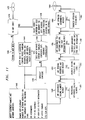
- Figure 9 illustrates the osps_config feature 280 that is used to engineer the operator services data by using data from existing source databases.
- the objective is to transfer operator services configuration from one configuration to another.
- the user will have to select the type of switching network signaling being used, the global switch modules, the new point code locations, and trunk equipment numbers.
- SEES will transfer the data from one hardware platform to another while reconfiguring the network to its new environment.
- the user starts from the engineering/create database feature. After selecting the osps_config feature 280, the user will use the dialing plan and network engineering features. Data is engineered from the office data administration tool data elements directly into the selected Abase&control@ or database location. The user is then required to input the target database 282. Call initoffice routine 284 checks for an existing target database and queries the user as to whether that database should be removed or whether new data will be added to the existing database. If new data is added, the existing database remains unchanged.
- the computer program calls the display variables (dis_vars) routine 286 to set and display selected variables such as lab, office data administration tool version. SEES does this task by using the env_menu routine to select the data from preexisting databases. Once found, this data is engineered into the target database. SEES then returns to the osps_config feature 280 to obtain a list of special network data elements from the selected source database or Abase&control. @ Only those data elements with containing. data are shown as a selection.
- the operator services configuration feature 280 shows all the data elements block 288 from the source database and allows the user to select the individual. data elements manually. This task is accomplished from a menu type screen with each form dynamically identified and selected by a number.
- the computer program then copies or dumps the user selected data elements into the target database or Abase&control. @ All data elements are error checked prior to the execution of the dump or copy. If the operation is an append to an existing database, then SEES dumps to an existing form. The formxfer routine is then called.
- the evlchg routine 290 takes one argument and the argument passed is the filename of the script that will be used to make the data changes when the evolve tool is executed. SEES then calls the evl_form routine 292.
- the evl form routine 292 takes two arguments. The first argument passed is the office data administration tool form name and the second argument is the filename where the contents of the office data administration tool form was dumped. This routine will check to see if there is a possible office data administration tool evolve to go between the two required generics and will perform all necessary step evolves to accomplish the tasks.
- the data elements block 288 proceeds to the formxfer block 294.
- the formxfer block 294 uses the dfixfer block 296 to calculate the new trunk members in accordance with the new operator services or lab configuration form user assigned OSPS equipment numbers. It will also differentiate information for the DSL assignments, TCP/IP DSL equipment, IP addresses to ports information, IP access numbers, and ETSI ISDN OSPS.
- the program dynamically writes an evolve script, provided an evolution pathway exists. This provides the manipulation of the data.
- the dfixfer block 296 The program then returns to osps_config after the evolve/transfer is completed.
- the osps_xfer routine 298 calculates the new OSPS equipment numbers in accordance with the new operator services or lab configuration from the user assigned information.
- Figure 10 illustrates the process of engineering a new operator services configuration database or data resource from at least one source database or source data resource.
- the user calls and starts 1400 the computer program.
- the computer program can be located on one machine (a computer device) or multiple machines virtually connected via a network file share capability allowing all the virtual machines to appear as one machine and containing all existing source databases or source data resources.
- a text or graphical user interface presents the main menu to the user allowing the user to select whether to browse existing source databases and source data resources or whether the user desires to create a new source database or engineer (modify) an existing source database from all or parts of other existing source databases or source data resources.
- the user When the user selects the operator services engineering feature, the user is required to select the location of the new operator services database 1402. Selecting means selecting an item from a menu or inputting information such that the computer can react to the instruction. In addition, the user must select whether the new or modified operator services database should be located on the same machine (computer) or a virtual machine (computer), should the operator services database be created or modified, and whether the operator services database should be inclusively updated.
- the location of the new database 1402 is confirmed 1404 with the user and if the confirmation is not correct, the computer program allows the user to reselect a different location 1402.
- the computer program searches or checks the node or location where the user intends for the new or modified operator services database to be located. This node check will confirm the actual location of the operator services database, and whether the node is free 1406 on the desired machine (computer). The computer program confirms whether the selected location of the new database is empty of existing data 1406. If the response from the user is yes, the computer program creates a new operator services_directory structure 1408. If the response is no, the program allows the user to delete the existing database 1410. If the database is deleted, the program removes the database structure 1412 and creates a new operator services directory structure 1408. The operator services directory structure can be created to hold similar and dissimilar size data as compared to the source databases.
- the computer program then allows the user to select the qualifying source databases available for use 1414.
- the source databases might have access utilities to assist the in the configuration of a new database.
- the computer program selects qualifying existing source data resources using the user set criteria in input when the user was prompted to select the lab, machine (computer), site, customer name, and software release.
- the computer program requires the user to select and input certain elements regarding the characteristics desired in the new operator services database to be created in order to search existing source databases and source data resources for existing data. For example, the user will be prompted to select the lab, the computer or machine, the site location of the new or modified operator services database, the customer name, the software release, and the version of the source database or source data resource.
- the program creates an index of pointers 1416 to the source databases and displays 1418 the choices of databases containing operator services position system (OSPS) configurations.
- the computer program queries the user as to whether the desired new operator services configuration will support European Transmission Standard Interface (ETSI) 1424, alternate mark inversion (AMI) 1428, or both1420. If the new database supports both ETSI and AMI, the computer program accesses a data structure that will support both 1422. If the new database supports only ETSI, the computer program accesses a data structure that will support ETSI 1426. If the new database supports only AMI, the computer program accesses a data structure that will support AMI 1430. Connector A 1432 connects Figure 10 with Figure 11.
- ETSI European Transmission Standard Interface
- AMI alternate mark inversion
- the computer program queries whether any configuration exists 1434 to support the new database. If not, the user is returned to the main menu 1436. If a configuration was selected, the user selects the OSPS database element locations in the source databases 1438. The computer program queries whether the new database has a similarly configured OSPS hardware configuration 1440. If not, the computer program allows the user to manually configure 1442 a new OSPS hardware configuration. If the new database contains a similarly configured OSPS hardware configuration, the computer program uses a best fit algorithm 1444 to compare the packet handling resources, digital line equipment, and digital facility resources.
- the computer program modifies the equipment numbers and network addresses 1446. Then it removes OSPS equipment numbers or network addresses for the equipment for digital subscriber line (DSL) assignments, TCP/IP DSL equipment, IP addresses to ports information, IP access numbers, and ETSI ISDN/OSPS.
- DSL digital subscriber line
- the computer program performs a series of queries that if required engineers the item in the query.
- the computer program prompts the user whether authorized calling numbers are needed 1448 and if the response is yes, the program engineers authorized calling numbers 1450.
- the computer program prompts the user whether booking priorities and codes are needed 1452 and if the response is yes, the program engineers the booking priorities and codes 1454.
- the computer program prompts the user whether announced text patterns and line code digit information are needed 1456 and if the response is yes, the program engineers the announced text patterns and line code digit information 1458.
- the computer program prompts the user whether operator assignments are needed 1460 and if the response is yes, the program engineers the operator assignments 1462.
- Connector B 1464 connects Figures 11 and Figures 12 together.
- the computer program prompts the user whether OSPS office options are needed 1466 and if the response is yes, the program engineers the OSPS office options 1468.
- the computer program prompts the user whether operator service center to office administration processor number mapping is needed 1470 and if the response is yes, the program engineers the operator service center to office administration processor number mapping 1472.
- the computer program prompts the user whether operator queue determinations are needed 1474 and if the response is yes, the program engineers the operator queue determinations 1476.
- the computer program prompts the user whether country code and international routing numbers are needed 1478 and if the response is yes, the program engineers the country code and international routing numbers 1480.
- the computer program prompts the user whether expanded operator queue determinations are needed 1482 and if the response is yes, the program engineers the expanded operator queue determinations 1484.
- the computer program extracts the data 1486 and the user selects the specific set of elements for the new database 1488.
- the computer program determines if this format is the same version or release as the new database structure 1490. This is accomplished by matching the selected criteria in the software release with the new or existing software release of the directory structure and name. If the format is not the same, the computer program determines if evolutionary pathways exist 1491. If the evolutionary pathways do not exist, the computer program aborts 1492. If the evolutionary pathways exist 1491, the program calls an evolution tool 1493, to modify the saved data so that consistency with the new location is maintained.
- the data is error checked 1494.
- the program dynamically manipulates and modifies the data 1498. All selected operator services data that is saved is loaded 1495 or merged into a new or existing operator services data resource using a platform utility that converts the data from an ASCII format to a binary format and loads the data into the database.
- the computer program displays 1496 all the statistics on the data elements as they are being loaded into the selected location. In addition, the computer program displays errors, updates, non-updates to the selected location data resource. The computer program then allows the user to return to the main menu or quit, (exit the program) 1497.
Abstract
Description
- This invention relates to a computer program that can create new operator services databases from all or parts of one or more existing operator services databases containing data information for the operation of data and voice audio telecommunication switches.
- The configuration of telecommunication switches usually occurs in at least three environments. First, during the testing of switch hardware and software, a laboratory switch is configured to the requirements established for the test. Second, when a switch is sold to a customer, the switch is configured to the customer=s specifications. Third, when a switch experiences a full failure, it often requires reconfiguration of the databases supporting the failed switch or configuration of new databases for an emergency backup switch or replacement switch. Normally, the configuration of telecommunication switches during these three environments requires the manual input of thousands and possibly millions of records of information. This process is extremely time consuming and can take weeks or months to complete.
- In the first environment, telecommunication companies continually test new versions of switch software, peripheral devices and other hardware devices during the life of a telecommunication switch. When testing software or hardware, switch engineers design different operating environments to establish operating parameters of the new software or hardware. Data engineers manually input data to configure the operation of the switch for the designed test. Usually, the configuration of the testing environment is performed on a data build machine (computer). The configuration of the switch to simulate the desired testing operational conditions often involves retesting archived configurations or modified archived configurations. Otherwise, the testing configuration is accomplished by manual data entry.
- In the second environment, telecommunication switches sold to customers are configured based on the customer=s intended operational conditions and requirements. Usually, the configurations for new switches are manually built new data configurations without relying on existing database configurations. However, the configuration of the features, switching software and hardware is often adopted from other existing configurations.
- The third operational environment is recovery of the switch after the switch has experienced a failure. These failures can result from equipment failure to natural disasters such as earthquakes, hurricanes or fires. Recovery of the failed switch sometimes requires the installation of an emergency backup switch. The emergency backup switch requires database configurations that replicate the databases in the damaged switch. Normally, the configuration of the emergency backup switch requires manual, time consuming input of data that will support specific customer features and routing of calls on the emergency backup switch. Having the ability to configure the telecommunication switch by transferring existing data information from known databases into new databases by automating the manual tasks of data entry would save considerable time, money and significantly improve productivity. In addition, instant access to many different switching systems is a critical task that currently requires many hours or days of research and manual browsing. A need exists for a robust process to automatically replace the current manual method data entry to configure operator services data for telecommunications switches.
- In order to automate the current manual data entry process of engineering operator services configuration databases, the computer program ofthis invention establishes a new database structure and mines source databases to load source operator services data into the new operator services database structure. The computer program is capable of searching for the desired data and automates many of the tasks for configuring a new operator services database from the source databases. This eliminates the current requirement for manual data entry for configuring new operator services databases for telecommunication switches.
- This computer program is multifunctional allowing for the browsing of all operator services databases prior to the configuration. Once the target operator services databases are determined, the computer program creates a new data directory structure and selectively copies all or part of the data from the source operator services databases into the new database.
- The invention selects the source databases, determines whether the operator services database supports European Transmission Standard Interface (ETSI), Alternate Mark Inversion (AMI), or both and modifies the equipment numbers and network addresses. The program removes the operator services positioning system (OSPS) equipment or network addresses for digital subscriber line (DSL) assignments, transmission control protocol/ Internet protocol (TCP/IP) DSL equipment, IP addresses to ports information, IP access numbers and ETSI ISDN/OSPS numbers. The program modifies the equipment and network addresses with the new data relating to the new location of the equipment numbers and addresses. The computer program performs a series of queries regarding the OSPS configuration and extracts the data. The data is evolved to the same software release if needed, and loaded into the new OSPS data directory structure.
- This invention provides accurate and timely customer information, significantly decreases the time interval for engineering a new operator services database, decreases the research and data entry time, decreases the interval for lab planning and project management, improves database integrity, provides a cleaner operator services database, reuses existing operator services data eliminating double data entry, reuses some existing software code, use preexisting tools, and provides a platform for future growth and expandability. By accomplishing these tasks, the telecommunication switch manufacturer or telecommunication switch operator saves time, money and decreases time-to-market product and service schedules.
- The summary of the invention, as well as the following detailed description of preferred embodiments, is better understood when read in conjunction with the accompanying drawings, which are included by way of example, and not by way of limitation with regard to the claimed invention.
- Figure 1 is a functional flow chart illustrating the logical operations of the main menu of the computer program.
- Figure 2 illustrates the various hardware components and database types used in conjunction with the computer program.
- Figure 3 illustrates the operation of the computer program as it builds a new database from parts of other databases.
- Figure 4 is a flow chart of the overall features exercised in the operation of the computer program.
- Figure 5 is a flow chart of the logical operation of the computer program.
- Figure 6 is a flow chart of the browse feature of the computer program.
- Figure 7 is a flow chart of the dialing plan feature configuration of the computer program.
- Figure 8 is a flow chart of the build database feature configuration of the computer program.
- Figure 9 is a flow chart of the build database feature of the computer program.
- Figure 10 is a flow chart of the operator services feature configuration of the computer program.
- Figure 11 is a flow chart of the operator services feature configuration of the computer program.
- Figure 12 is a flow chart of the operator services feature configuration of the computer program.
- Figure 1 illustrates the logical operation of the main menu of the user interface for the Simple Environment Engineering System (ASEES@) computer program. If the SEES program is wrongly selected as the application of choice by the user, the
main menu display 10 allows the user to exit 11 the computer program without choosing any ofthe functions. If SEES is selected as the program of choice by the user, from themain menu display 10, the user can choose seven operations. - These operations include: about
SEES 12, peripheral interface data bus/ peripheral interface control bus (PIDB/PICB) 13, browsefeature 14, labconfiguration document reports 16, query byunit 18, create anew database 22, or engineer anexisting database 24. About SEES 12 is documentation about the computer program and the operations and features that a user can implement. Peripheral interface data bus (PIDB)/ peripheral interface control bus (PICB) 13 allows a user to examine the peripheral units in the switching modules as they are connected to the interface control and data buses. - The
browse feature 14 allows users to view the location and type of data in other databases. This feature allows the user to search for and find the desired data prior to generating new data from scratch The labconfiguration document reports 16 provide data on all the hardware for a given lab or for a customer=s switch. Query byunit 18 identifies hardware items, features, signaling types, or other elements of the switch across many databases containing information on lab switches, manufacturers= switches, and/or customers= switches. Query byunit 18 also specifies and conforms targeting specific software releases to common versions. - The last two operations, create a new database and modify an existing database, have a guard
dog authorization screen 20 that prevents entry by unauthorized users into the program. Entry by unauthorized users beyond the browse feature impact existing source databases and source data resources. Allowing unauthorized users to create and modify existing source databases and source data resources can have severe effects on other operations due to the unintended destruction of valuable data. The computer program will query the user or the user=s computer for authorization to gain access to those features of the program that allow for the creation or modification of operator services databases or data resources. Typical authorized users are data engineers. Once the screening process is complete, access is permitted, and another text or graphical user interface menu is displayed that allows the user to select features other than browse. From all six of these operations, a user can exit 11 the program. - The computer program uses all current data environments and employs functions to ensure that different versions of various software databases are converted to a common version. SEES provides accurate configuration information to customers on all environments to the switch module. SEES uses an office data administration tool called Ainit-office@ to insure a clean initial database structure. SEES automatically updates the newest office data administration tool issues and environments.
- Figure 2 illustrates the various hardware components used in conjunction with a
telecommunications switch 33. Adata build machine 26 is used to create the data information used in the operation of atelecommunications switch 33. The data buildmachine 26 usually contains or has access to the source databases such theoffice dependant database 28, theequipment configuration database 30, the officedata administration tools 32, andother configuration databases 35. The SEES computer program located on the data buildmachine 26 relies on various tools or routines to help in the execution of its operation. - Also connected to the data build
machine 26 are a variety of personal computers orwork stations 27. The data buildmachine 26 is also connected to aswitch interface processor 25. Theswitch interface processor 25 is capable of connecting to other data build machines or communication switches 33. Theconnection 56 between theswitch interface processor 25 and other communication switches 33 or data build machines can be a physical link such as a communication line (fiber, coaxial cable, twisted pair, etc.) or a nonphysical link such as transferring tapes or disks containing the data. Other communication links include radio frequency (RF) links by satellite transmission of data or wireless transmission of data. - Many telecommunication switches 33 have redundant administration modules represented by a zero
side 34 and a oneside 36. The redundantadministrative modules side 38 and a oneside 40. Theadministration modules communication modules communication links 42. The cross linking ofadministration modules communication modules communication link 44 to thecommunication modules switch modules telecommunication switch 33 has at least one switch module (SM). The Lucent Technologies= SESS Switch can currently support up to 192 switch modules connected to theadministrative modules communication modules - The
equipment configuration database 30 contains information regarding theadministration modules communication modules 38 and 40 (encompassing items corresponding to bracket 58 in Figure 2). Theequipment configuration database 30 keeps track of all the equipment hardware associated with thetelecommunication switch 33 including the various equipment types ofthe hardware such as tape units, circuit packs, administration module links and disks containing the software versions used in conjunction with the hardware and all associated resources. - The office
dependent database 28 contains information regarding part of thecommunication modules switch modules bracket 60 in Figure 2). The officedependent database 28 is loaded on the memory disk in theadministration modules dependent database 28 provides call set up, functional feature capability of the switch modules, and defines all switch module hardware configuration information. - Figure 3 illustrates the operation of the Simple Environment Engineering System as it builds a new database from parts of other databases. In a typical setting, DB-1 62 contains information regarding features such as rate and routing information. DB-2 64 contains dialing information such as specific switch module configurations and networking rate and routing information. DB-3 66 contains hardware platform information such as additional switch module configurations. DB-
n 68 are other databases in the data warehouse 70 containing information such as additional features or hardware. SEES identification routines browse the data warehouse 70 looking for desired components for reuse. In thedatabase section modifier 72, SEES pulls new components from the various databases in the data warehouse 70 and with some modification such as altering the hardware designations for the software data, SEES creates anew database 74. - Figure 4 illustrates the overall features of SEES. ASEES calls@ 100 is a routine that calls other components of the program such as the make menu user interface (mkmenu) routine 110. The SEES= user interface allows a user to incorporate a variety of utilities including UNIX, web based languages, directories, databases, office data administration tools, DOS, and other applications. The make menu (mkmenu) routine 110 can be set up to use menu driven utilities employing streamlined commands, shortcuts, object menus, pictures or icons.
- From the
user interface screen 110, the user can callfunctions 111 that implement the various configuration features of the computer program. Thebrowse feature 124 restricts users to a read only environment but because of this restriction, allows many more unsophisticated users to use SEES to view the various databases used in the operation of atelecommunication switch 33. For more sophisticated users who have authorization to get past theguard dog 20, SEES queries as to whether a new database will be created 153 or whether an existing database will be modified 155. Either choice allows the user to select the from the seven configuration scheme features of SEES. - The first feature of SEES is the
hardware engineering module 156. This module includes theequipment configuration block 160 that allows users to examine the properties oftheadministrative modules communication modules telecommunication switch 33. The office dependentdatabase hardware block 162 contains information allowing the communication between thecommunication modules switch modules - The second feature of SEES is the dialing
plan engineering module 158. The dialingplan engineering module 158 includes thefeature engineering block 164, the signalnetwork engineering block 166 and the dialingplan engineering block 168. Thefeature engineering block 164 pulls existing features from other databases that contain feature definitions with embedded office dependant information into the new environment modified to the new database. The signalnetwork engineering module 166 transfers data content regarding signaling information. The dialingplan engineering module 168 maps numbers that differentiate the route of the call and defines everything that is not hardware routing, trunking, lines, subscribers, and complete customer calling information. - The third feature of SEES is the
network engineering module 170. Thenetwork engineering module 170 includes the signaling system 7 (ss7) block 174, theNA7 block 176, the ISDN user part (ISUP) block 178, the TUP block 180 and the British Telecom 7 (BT7) block 182. Other blocks can also be added that focus on the international standard of particular countries or particular telecommunication companies. - The fourth feature of SEES is the operator services feature 172. The operator services feature allows
telecommunication switch 33 customers to connect operator services to thetelecommunication switch 33. These services include but are not limited to directory assistance, automatic call distributor/distribution, toll and assistance applications, administrator measurements-operator, automated calling card services, automated operator trainer, automatic call distribution (ACD), busy line verification, and emergency alerts. - The fifth feature of SEES is the private
branch exchange module 159. The privatebranch exchange module 159 is used to configure databases related to private branch exchange networks. - The sixth feature of the computer program is the
intelligent network module 173. Theintelligent network module 173 includes thedialing plan module 158, thehardware engineering module 156, and thenetwork engineering module 170. These three components should be implemented prior to performing an intelligent network configuration. - The seventh feature of the computer program is the
wireless module 171. Thewireless module 171 includes thedialing plan module 158, thehardware engineering module 156, and thenetwork engineering module 170. These three components should be implemented prior to performing a wireless configuration. - Figure 5 is a flow chart of the logical operation of Simple Environment Engineering System. SEES 100 accesses
variables 102 by calling thesetev routine 106, the name variable (name_vars) routine 108 and the make menu (mkmenu) routine 110. Thesetev routine 106 sets the office data administration variables. Thesetev routine 106 also sets the office data administration environmental variables that provides a description of the functionality that setev routine 106 provides. The name variable (name_vars) routine 108 sets certain variable values. The name variables (name_vars) routine 108 defineslegal values 112 for lab, release and enviss. Lab is the total testing environment that simulates the product being sold to the customer. Release is the hardware, software options (SWOPT), equipment configuration database and the office dependant database relating to thetelecommunication switch 33 being used by SEES in thecreation 153 ormodification 155 of a database. The enviss routine is the environment tool version that the office data administration is supporting. The make menu (mkmenu) routine 110 sets up themain menu 114 and calls a display variable (disp_vars) routine 116, then calls any selection made by the user. - From the make menu (mkmenu) routine 110, the user can access the
loadc_menu routine 120 that expands the parameters or values and allows them to reset lab, release and enviss. The make menu (mkmenu) routine 110 also allows the user to accessbrowse 124, and the create anew database 153 or build an existingdatabase 155. To access either create a new database or build an existing database, the user must first pass aguard dog 20. Theguard dog 20 functions as a screen permitting only authorized users into these sensitive areas of the data buildmachine 26 to either create 153 or modify 155 databases. Thebrowse feature 124 allows users to view hardware and software configurations on known telecommunication switches 33. - Figure 6 illustrates the
browse feature 124. Thebrowse feature 124 allows the user to select theenvironment 132, then calls the display equipment (dis_eq) routine 134, the display packs (disp_paks) routine 136, the display features (disp_feat) routine 138, the display equipment number (disp_ens) routine 140 and the display the test user guide (disp_tug) routine 142. The display equipment (dis_eq) routine 134 displays all switch module and unit configuration within the switch module. The dumpdf routine 13.5 is used on all eq* forms (equipment related data) 137 in the selected circuit packs. The display packs (dip_pak) routine 136 displays all circuit packs 144 and their locations. The display packs (disp_paks) routine 136 uses dumpdf 135 after extracting the appropriate data to view from the office data administration makefdt command 146. The display feature (disp_feat) routine 138 displays the feature information based on specific hardcoded selections by accessing the mapped relations (data structures) 148. If the mapped relations (data structures) 148 are missing or removed, amessage 150 will display indicating this condition. The display equipment number (disp_ens) routine 140 displays all equipment numbers by cutting theline equipment numbers 152 out of thedata structures 154 and optionally, converts them using thelen2port command 103 under oddtools/bin 101. The display test user guide (disp_tug) routine 142, an optional routine, automates the testenvironment user guide 161. - Figure 7 illustrates the dialing plan configuration (dp_config) routine. The user is prompted for the target Abase&control@ 181. Base&control is the location where the new database is created and manipulated. If the user responds yes 183, then the computer program calls the office data
administration tool initoffice 185. Init-office 185 builds a database structure containing no data. Init-office 185 calls an office data administration tool that confirms that the correct version ofvars 108 is running. If the user responds no 187, then the computer program searches 189 all of the office dependent databases. This function will show only one selected source environment. Then it will determine those data elements in the data elements database that are empty 191. It will then display all data elements as a menu. The computer program then selects the data elements to load 193 and takes all choices and loads them into thenew database structure 195. As the load process continues, allmessages 197 will show on the screen then the last menu will request input for ending thedialing plan configuration 199. - Figure 8 illustrates the build database feature. The user is prompted for the target Abase&control@ 201. From the response to the
new location 203, then the computer program calls the office data administration tool init-office 205. The init-office routine 205 builds a database structure containing no data. The init-office routine calls 205 an office data administration tool that confirms that the correct version of vars is running. If the user responds no 207, then the computer program searches 209 all of the office dependent databases. This function will show all features and display all switching module configurations available to load into thedata elements 211. The program will then allow the user to select those switching modules to load in thenew data structure 213. The program takes all the user selected choices and loads them into thenew database structure 215. As the load process continues, allmessages 217 will show on the screen then the last menu will request input for ending thedialing plan configuration 219. - Figure 9 illustrates the osps_config feature 280 that is used to engineer the operator services data by using data from existing source databases. The objective is to transfer operator services configuration from one configuration to another. The user will have to select the type of switching network signaling being used, the global switch modules, the new point code locations, and trunk equipment numbers. SEES will transfer the data from one hardware platform to another while reconfiguring the network to its new environment.
- The user starts from the engineering/create database feature. After selecting the
osps_config feature 280, the user will use the dialing plan and network engineering features. Data is engineered from the office data administration tool data elements directly into the selected Abase&control@ or database location. The user is then required to input thetarget database 282. Callinitoffice routine 284 checks for an existing target database and queries the user as to whether that database should be removed or whether new data will be added to the existing database. If new data is added, the existing database remains unchanged. - The computer program calls the display variables (dis_vars) routine 286 to set and display selected variables such as lab, office data administration tool version. SEES does this task by using the env_menu routine to select the data from preexisting databases. Once found, this data is engineered into the target database. SEES then returns to the osps_config feature 280 to obtain a list of special network data elements from the selected source database or Abase&control. @ Only those data elements with containing. data are shown as a selection.
- The operator
services configuration feature 280 shows all the data elements block 288 from the source database and allows the user to select the individual. data elements manually. This task is accomplished from a menu type screen with each form dynamically identified and selected by a number. - The computer program then copies or dumps the user selected data elements into the target database or Abase&control. @ All data elements are error checked prior to the execution of the dump or copy. If the operation is an append to an existing database, then SEES dumps to an existing form. The formxfer routine is then called.
- The
evlchg routine 290 takes one argument and the argument passed is the filename of the script that will be used to make the data changes when the evolve tool is executed. SEES then calls theevl_form routine 292. The evl form routine 292 takes two arguments. The first argument passed is the office data administration tool form name and the second argument is the filename where the contents of the office data administration tool form was dumped. This routine will check to see if there is a possible office data administration tool evolve to go between the two required generics and will perform all necessary step evolves to accomplish the tasks. - The data elements block 288 proceeds to the
formxfer block 294. Theformxfer block 294 uses thedfixfer block 296 to calculate the new trunk members in accordance with the new operator services or lab configuration form user assigned OSPS equipment numbers. It will also differentiate information for the DSL assignments, TCP/IP DSL equipment, IP addresses to ports information, IP access numbers, and ETSI ISDN OSPS. The program dynamically writes an evolve script, provided an evolution pathway exists. This provides the manipulation of the data. Thedfixfer block 296. The program then returns to osps_config after the evolve/transfer is completed. - The
osps_xfer routine 298 calculates the new OSPS equipment numbers in accordance with the new operator services or lab configuration from the user assigned information. Theck_psu routine 300 will check all available resources on the PSU=s for room to support the transitioned links. SEES then returns the user to osps_config after the evolve/transfer is completed. The user is then prompted as to whether the user wants to exit 302 or return to the main menu. - Figure 10 illustrates the process of engineering a new operator services configuration database or data resource from at least one source database or source data resource. The user calls and starts 1400 the computer program. The computer program can be located on one machine (a computer device) or multiple machines virtually connected via a network file share capability allowing all the virtual machines to appear as one machine and containing all existing source databases or source data resources. In the main menu of the computer program, a text or graphical user interface presents the main menu to the user allowing the user to select whether to browse existing source databases and source data resources or whether the user desires to create a new source database or engineer (modify) an existing source database from all or parts of other existing source databases or source data resources.
- When the user selects the operator services engineering feature, the user is required to select the location of the new
operator services database 1402. Selecting means selecting an item from a menu or inputting information such that the computer can react to the instruction. In addition, the user must select whether the new or modified operator services database should be located on the same machine (computer) or a virtual machine (computer), should the operator services database be created or modified, and whether the operator services database should be inclusively updated. The location of thenew database 1402 is confirmed 1404 with the user and if the confirmation is not correct, the computer program allows the user to reselect adifferent location 1402. - The computer program searches or checks the node or location where the user intends for the new or modified operator services database to be located. This node check will confirm the actual location of the operator services database, and whether the node is free 1406 on the desired machine (computer). The computer program confirms whether the selected location of the new database is empty of existing
data 1406. If the response from the user is yes, the computer program creates a newoperator services_directory structure 1408. If the response is no, the program allows the user to delete the existingdatabase 1410. If the database is deleted, the program removes thedatabase structure 1412 and creates a new operatorservices directory structure 1408. The operator services directory structure can be created to hold similar and dissimilar size data as compared to the source databases. - If the existing database structure is not deleted, or the program created a new operator services directory structure, the computer program then allows the user to select the qualifying source databases available for
use 1414. The source databases might have access utilities to assist the in the configuration of a new database. The computer program then selects qualifying existing source data resources using the user set criteria in input when the user was prompted to select the lab, machine (computer), site, customer name, and software release. The computer program requires the user to select and input certain elements regarding the characteristics desired in the new operator services database to be created in order to search existing source databases and source data resources for existing data. For example, the user will be prompted to select the lab, the computer or machine, the site location of the new or modified operator services database, the customer name, the software release, and the version of the source database or source data resource. - The program creates an index of
pointers 1416 to the source databases and displays 1418 the choices of databases containing operator services position system (OSPS) configurations. The computer program queries the user as to whether the desired new operator services configuration will support European Transmission Standard Interface (ETSI) 1424, alternate mark inversion (AMI) 1428, or both1420. If the new database supports both ETSI and AMI, the computer program accesses a data structure that will support both 1422. If the new database supports only ETSI, the computer program accesses a data structure that will supportETSI 1426. If the new database supports only AMI, the computer program accesses a data structure that will supportAMI 1430.Connector A 1432 connects Figure 10 with Figure 11. - The computer program queries whether any configuration exists 1434 to support the new database. If not, the user is returned to the
main menu 1436. If a configuration was selected, the user selects the OSPS database element locations in thesource databases 1438. The computer program queries whether the new database has a similarly configured OSPS hardware configuration 1440. If not, the computer program allows the user to manually configure 1442 a new OSPS hardware configuration. If the new database contains a similarly configured OSPS hardware configuration, the computer program uses abest fit algorithm 1444 to compare the packet handling resources, digital line equipment, and digital facility resources. - The computer program modifies the equipment numbers and network addresses 1446. Then it removes OSPS equipment numbers or network addresses for the equipment for digital subscriber line (DSL) assignments, TCP/IP DSL equipment, IP addresses to ports information, IP access numbers, and ETSI ISDN/OSPS.
- The computer program performs a series of queries that if required engineers the item in the query. The computer program prompts the user whether authorized calling numbers are needed 1448 and if the response is yes, the program engineers authorized calling
numbers 1450. The computer program prompts the user whether booking priorities and codes are needed 1452 and if the response is yes, the program engineers the booking priorities andcodes 1454. The computer program prompts the user whether announced text patterns and line code digit information are needed 1456 and if the response is yes, the program engineers the announced text patterns and linecode digit information 1458. The computer program prompts the user whether operator assignments are needed 1460 and if the response is yes, the program engineers theoperator assignments 1462.Connector B 1464 connects Figures 11 and Figures 12 together. - The computer program prompts the user whether OSPS office options are needed 1466 and if the response is yes, the program engineers the
OSPS office options 1468. The computer program prompts the user whether operator service center to office administration processor number mapping is needed 1470 and if the response is yes, the program engineers the operator service center to office administrationprocessor number mapping 1472. The computer program prompts the user whether operator queue determinations are needed 1474 and if the response is yes, the program engineers theoperator queue determinations 1476. The computer program prompts the user whether country code and international routing numbers are needed 1478 and if the response is yes, the program engineers the country code andinternational routing numbers 1480. The computer program prompts the user whether expanded operator queue determinations are needed 1482 and if the response is yes, the program engineers the expandedoperator queue determinations 1484. - The computer program extracts the
data 1486 and the user selects the specific set of elements for thenew database 1488. The computer program determines if this format is the same version or release as thenew database structure 1490. This is accomplished by matching the selected criteria in the software release with the new or existing software release of the directory structure and name. If the format is not the same, the computer program determines if evolutionary pathways exist 1491. If the evolutionary pathways do not exist, the computer program aborts 1492. If the evolutionary pathways exist 1491, the program calls anevolution tool 1493, to modify the saved data so that consistency with the new location is maintained. - If the format is the same version or release as the
new database structure 1490, or after the evolution of data has occurred 1493, the data is error checked 1494. The program dynamically manipulates and modifies thedata 1498. All selected operator services data that is saved is loaded 1495 or merged into a new or existing operator services data resource using a platform utility that converts the data from an ASCII format to a binary format and loads the data into the database. The computer program displays 1496 all the statistics on the data elements as they are being loaded into the selected location. In addition, the computer program displays errors, updates, non-updates to the selected location data resource. The computer program then allows the user to return to the main menu or quit, (exit the program) 1497.
Claims (41)
- A process for configuring an operator services database comprising the steps of:searching a source database for operator services equipment data fields;selecting operator services equipment data from the operator services equipment data fields;copying the operator services equipment data from the source database to a new database; andmatching subscribers to the operator services equipment data in the new database.
- The process for configuring an operator services database described in claim 1, where the operator services equipment data from the source database is copied to similar sized data structure in the new database.
- The process for configuring an operator services database described in claim 1, where the operator services equipment data from the source database is copied to dissimilar sized data structure in the new database.
- The process for configuring an operator services database described in claim 1, where the operator services equipment data are DSL assignments data.
- The process for configuring an operator services database described in claim 1, where the operator services equipment data are TCP/IP assignments data.
- The process for configuring an operator services database described in claim 1, where the operator services equipment data are IP addresses.
- The process for configuring an operator services database described in claim 1, where the operator services equipment data are IP addresses to ports data.
- The process for configuring an operator services database described in claim 1, where the digit analysis data elements are digit tables.
- The process for configuring an operator services database described in claim 1, where the operator services equipment data are IP access number data.
- The process for configuring an operator services database described in claim 1, where the operator services equipment data are ETSI operator services data.
- The process for configuring an operator services database described in claim 1, where the operator services equipment data are AMI operator services data.
- The process for configuring an operator services database described in claim 1, where the operator services equipment data are both ETSI and AMI operator services data.
- The process for configuring an operator services database described in claim 1, further comprises the step of determining if authorized calling numbers are needed in the new database.
- The process for configuring an operator services database described in claim 13, further comprises the step of engineering authorized calling numbers if needed in the new database.
- The process for configuring an operator services database described in claim 1, further comprises the step of determining if booking priorities are needed in the new database.
- The process for configuring an operator services database described in claim 15, further comprises the step of engineering booking priorities if needed in the new database.
- The process for configuring an operator services database described in claim 1, further comprises the step of determining if engineering booking priorities and codes are needed in the new database.
- The process for configuring an operator services database described in claim 17, further comprises the step of engineering booking priorities and codes if needed in the new database.
- The process for configuring an operator services database described in claim 1, further comprises the step of determining if announced text patterns are needed in the new database.
- The process for configuring an operator services database described in claim 19, further comprises the step of engineering announced text patterns if needed in the new database.
- The process for configuring an operator services database described in claim 1, further comprises the step of determining if announced text patterns and line code digit information is needed in the new database.
- The process for configuring an operator services database described in claim 21, further comprises the step of engineering announced text patterns and line code digit information if needed in the new database.
- The process for configuring an operator services database described in claim 1, further comprises the step of determining if operator assignments are needed in the new database.
- The process for configuring an operator services database described in claim 23, further comprises the step of engineering operator assignment if needed in the new database.
- The process for configuring an operator services database described in claim 1, further comprises the step of determining if operator services office options are needed in the new database.
- The process for configuring an operator services database described in claim 25, further comprises the step of engineering operator services office options if needed in the new database.
- The process for configuring an operator services database described in claim 1, further comprises the step of determining if an operator service center to office administration processor number mapping is needed in the new database.
- The process for configuring an operator services database described in claim 27, further comprises the step of engineering an operator service center to office administration processor number mapping if needed in the new database.
- The process for configuring an operator services database described in claim 1, further comprises the step of determining if number of directory inquiries information is needed in the new database.
- The process for configuring an operator services database described in claim 29, further comprises the step of engineering number of directory inquiries information if needed in the new database.
- The process for configuring an operator services database described in claim 1, further comprises the step of determining if country code routing numbers are needed in the new database.
- The process for configuring an operator services database described in claim 31, further comprises the step of engineering country code routing numbers if needed in the new database.
- The process for configuring an operator services database described in claim 1, further comprises the step of determining if international routing numbers are needed in the new database.
- The process for configuring an operator services database described in claim 33, further comprises the step of engineering international routing numbers if needed in the new database.
- A process for configuring an operator services database consisting of the steps of:selecting an operator services database engineering computer program;selecting characteristics desired in the new operator services database;selecting a location of the new operator services database;creating an operator services data directory structure for the new operator services database capable of receiving new data copied from the at least one source database;selecting from the at least one source database, source data for copying into the operator services data directory structure;creating an index of data elements for the at least one source database;creating an index of operator services data from the at least one source database;converting the operator services data in the operator services data directory structure from a binary format to an ASCII format;copying the ASCII formatted data into a memory structure;determining if the ASCII formatted data is the same version or release as the new operator services data directory structure;evolving the ASCII formatted data if the ASCII formatted data is not the same;merging the ASCII formatted data into the operator services data directory structure;converting the ASCII formatted data to a binary formatted data; andloading the binary formatted data into the operator services data directory structure.
- The process for configuring an operator services database described in claim 35, further comprising the step of locating the operator services database engineering computer program on one machine.
- The process for configuring an operator services database described in claim 35, further comprising the step of locating the operator services database engineering computer program on multiple machines virtually connected via a network file share capability.
- The process for configuring an operator services database described in claim 35, further comprising the step of locating the operator services database engineering computer program on multiple machines virtually connected via a network file share capability allowing all the virtual machines to appear as one machine and containing all existing source databases or source data resources.
- The process for configuring an operator services database described in claim 35, further comprising the step synchronizing at least one source database having access utilities with the same versions that correspond to additional source databases.
- The process for configuring an operator services database described in claim 35, further comprising the step of checking the location where the new operator services data directory structure will be located for the existence of data.
- The process for configuring an operator services database described in claim 35, where the synchronizing at least one source database has access utilities.
Applications Claiming Priority (2)
| Application Number | Priority Date | Filing Date | Title |
|---|---|---|---|
| US09/054,206 US6243712B1 (en) | 1998-04-02 | 1998-04-02 | Method for creating and modifying similar and dissimilar databases for use in operator services configurations for telecommunications systems |
| US54206 | 1998-04-02 |
Publications (3)
| Publication Number | Publication Date |
|---|---|
| EP0948181A2 true EP0948181A2 (en) | 1999-10-06 |
| EP0948181A3 EP0948181A3 (en) | 2000-05-10 |
| EP0948181B1 EP0948181B1 (en) | 2013-01-23 |
Family
ID=21989459
Family Applications (1)
| Application Number | Title | Priority Date | Filing Date |
|---|---|---|---|
| EP99302439A Expired - Lifetime EP0948181B1 (en) | 1998-04-02 | 1999-03-29 | Method for creating and modifying similar and dissimilar databases for use in operator services configurations for telecommunication system |
Country Status (3)
| Country | Link |
|---|---|
| US (1) | US6243712B1 (en) |
| EP (1) | EP0948181B1 (en) |
| JP (2) | JP4015316B2 (en) |
Cited By (2)
| Publication number | Priority date | Publication date | Assignee | Title |
|---|---|---|---|---|
| GB2429874A (en) * | 2005-09-02 | 2007-03-07 | Motorola Inc | Network element manager resynchronization |
| GB2528479A (en) * | 2014-07-23 | 2016-01-27 | Gamma Telecom Ltd | Session handling in a communications network |
Families Citing this family (3)
| Publication number | Priority date | Publication date | Assignee | Title |
|---|---|---|---|---|
| US6453032B1 (en) * | 1998-04-02 | 2002-09-17 | Lucent Technologies Inc. | Method for creating and modifying similar and dissimilar databases for use in dialing plan configurations for telecommunication systems |
| US7076476B2 (en) * | 1999-03-02 | 2006-07-11 | Microsoft Corporation | Method and system for integrated service administration via a directory service |
| US7099883B2 (en) * | 2002-03-06 | 2006-08-29 | International Business Machines Corporation | System and method of linking dissimilar databases using pointers |
Citations (2)
| Publication number | Priority date | Publication date | Assignee | Title |
|---|---|---|---|---|
| US5274802A (en) | 1991-02-22 | 1993-12-28 | Gte Mobilnet Incorporated | Method for restoring lost databases by comparing existing database and generic database, and generating cellular switch commands to update the generic database |
| WO1996025715A1 (en) | 1995-02-13 | 1996-08-22 | British Telecommunications Public Limited Company | A method and apparatus for building a telecommunications network database |
Family Cites Families (8)
| Publication number | Priority date | Publication date | Assignee | Title |
|---|---|---|---|---|
| US5414812A (en) | 1992-03-27 | 1995-05-09 | International Business Machines Corporation | System for using object-oriented hierarchical representation to implement a configuration database for a layered computer network communications subsystem |
| US5506897C1 (en) * | 1993-02-22 | 2001-12-11 | Murex Securities Ltd | Automatic routing system for telephonic services |
| US5625804A (en) | 1995-04-17 | 1997-04-29 | International Business Machines Corporation | Data conversion in a multiprocessing system usable while maintaining system operations |
| JP2836541B2 (en) * | 1995-09-20 | 1998-12-14 | 日本電気株式会社 | Database update processing method |
| US5875242A (en) * | 1996-07-26 | 1999-02-23 | Glaser; Lawrence F. | Telecommunications installation and management system and method |
| JP3638059B2 (en) * | 1996-07-26 | 2005-04-13 | Kddi株式会社 | Subscriber data relocation apparatus and method |
| JPH1056668A (en) * | 1996-08-08 | 1998-02-24 | Fujitsu Ltd | Subscriber information transfer method |
| US5937048A (en) * | 1997-06-05 | 1999-08-10 | Bell Atlantic Network Services, Inc. | Program controlled switch provisioning |
-
1998
- 1998-04-02 US US09/054,206 patent/US6243712B1/en not_active Expired - Lifetime
-
1999
- 1999-03-29 EP EP99302439A patent/EP0948181B1/en not_active Expired - Lifetime
- 1999-04-02 JP JP09576199A patent/JP4015316B2/en not_active Expired - Fee Related
-
2007
- 2007-07-30 JP JP2007196857A patent/JP4833165B2/en not_active Expired - Fee Related
Patent Citations (2)
| Publication number | Priority date | Publication date | Assignee | Title |
|---|---|---|---|---|
| US5274802A (en) | 1991-02-22 | 1993-12-28 | Gte Mobilnet Incorporated | Method for restoring lost databases by comparing existing database and generic database, and generating cellular switch commands to update the generic database |
| WO1996025715A1 (en) | 1995-02-13 | 1996-08-22 | British Telecommunications Public Limited Company | A method and apparatus for building a telecommunications network database |
Non-Patent Citations (1)
| Title |
|---|
| ZITZEN W: "NTZ Nachrichtentechnische Zeitschrift", vol. 48, August 1995, VDE VERLAG GMBH, article "Integriertes Netzmanagement Fur Campus- Und Weitverkehrsnetz", pages: 12 - 15 |
Cited By (3)
| Publication number | Priority date | Publication date | Assignee | Title |
|---|---|---|---|---|
| GB2429874A (en) * | 2005-09-02 | 2007-03-07 | Motorola Inc | Network element manager resynchronization |
| GB2429874B (en) * | 2005-09-02 | 2007-09-19 | Motorola Inc | Network element manager resynchronization |
| GB2528479A (en) * | 2014-07-23 | 2016-01-27 | Gamma Telecom Ltd | Session handling in a communications network |
Also Published As
| Publication number | Publication date |
|---|---|
| EP0948181B1 (en) | 2013-01-23 |
| EP0948181A3 (en) | 2000-05-10 |
| JP4833165B2 (en) | 2011-12-07 |
| JP2000032512A (en) | 2000-01-28 |
| JP2007312423A (en) | 2007-11-29 |
| US6243712B1 (en) | 2001-06-05 |
| JP4015316B2 (en) | 2007-11-28 |
Similar Documents
| Publication | Publication Date | Title |
|---|---|---|
| US6055227A (en) | Method for creating and modifying similar and dissimilar databases for use in network configurations for telecommunication systems | |
| US6324547B1 (en) | Method for creating and modifing similar and dissimilar databases for use in intelligent network configurations for telecommunication systems | |
| US5875242A (en) | Telecommunications installation and management system and method | |
| EP0673135B1 (en) | Network support system | |
| US6301477B1 (en) | Method for creating and modifying similar and dissimilar databases for use in GSM wireless network configurations for telecommunication systems | |
| US20050078611A1 (en) | Flexible network platform and call processing system | |
| US20040052343A1 (en) | Telecommunications installation and management system and method | |
| US6108669A (en) | Method and apparatus for creating and modifying databases derived from a database warehouse for a telecommunication system | |
| US6169994B1 (en) | Method for creating and modifying similar and dissimilar databases for use in hardware equipment configurations for telecommunication systems | |
| US5222128A (en) | Telecommunication disaster plan | |
| JP4833165B2 (en) | How to configure the operator service database | |
| EP0924943B1 (en) | Method and system for merging telephone switching office databases | |
| US6272496B1 (en) | Method for creating and modifying similar and dissimilar databases for use in private branch exchange configurations for telecommunication systems | |
| EP1641288B1 (en) | Method for creating and modifying similar and dissimilar databases for use in dialing plan configurations | |
| Nogueira et al. | On the development and use of a distributed management platform for telecom plants |
Legal Events
| Date | Code | Title | Description |
|---|---|---|---|
| PUAI | Public reference made under article 153(3) epc to a published international application that has entered the european phase |
Free format text: ORIGINAL CODE: 0009012 |
|
| AK | Designated contracting states |
Kind code of ref document: A2 Designated state(s): DE FR GB |
|
| AX | Request for extension of the european patent |
Free format text: AL;LT;LV;MK;RO;SI |
|
| PUAL | Search report despatched |
Free format text: ORIGINAL CODE: 0009013 |
|
| AK | Designated contracting states |
Kind code of ref document: A3 Designated state(s): AT BE CH CY DE DK ES FI FR GB GR IE IT LI LU MC NL PT SE |
|
| AX | Request for extension of the european patent |
Free format text: AL;LT;LV;MK;RO;SI |
|
| RIC1 | Information provided on ipc code assigned before grant |
Free format text: 7H 04M 3/42 A, 7H 04M 3/22 B, 7H 04Q 3/00 B |
|
| 17P | Request for examination filed |
Effective date: 20001026 |
|
| AKX | Designation fees paid |
Free format text: DE FR GB |
|
| 17Q | First examination report despatched |
Effective date: 20050422 |
|
| 17Q | First examination report despatched |
Effective date: 20050422 |
|
| RAP3 | Party data changed (applicant data changed or rights of an application transferred) |
Owner name: LUCENT TECHNOLOGIES INC. |
|
| REG | Reference to a national code |
Ref country code: DE Ref legal event code: R079 Ref document number: 69944595 Country of ref document: DE Free format text: PREVIOUS MAIN CLASS: H04M0003420000 Ipc: H04Q0003545000 |
|
| GRAP | Despatch of communication of intention to grant a patent |
Free format text: ORIGINAL CODE: EPIDOSNIGR1 |
|
| RIC1 | Information provided on ipc code assigned before grant |
Ipc: H04Q 3/545 20060101AFI20120614BHEP |
|
| RAP1 | Party data changed (applicant data changed or rights of an application transferred) |
Owner name: ALCATEL-LUCENT |
|
| GRAS | Grant fee paid |
Free format text: ORIGINAL CODE: EPIDOSNIGR3 |
|
| GRAA | (expected) grant |
Free format text: ORIGINAL CODE: 0009210 |
|
| AK | Designated contracting states |
Kind code of ref document: B1 Designated state(s): DE FR GB |
|
| REG | Reference to a national code |
Ref country code: GB Ref legal event code: FG4D |
|
| REG | Reference to a national code |
Ref country code: DE Ref legal event code: R096 Ref document number: 69944595 Country of ref document: DE Effective date: 20130321 |
|
| REG | Reference to a national code |
Ref country code: GB Ref legal event code: 732E Free format text: REGISTERED BETWEEN 20130829 AND 20130904 |
|
| REG | Reference to a national code |
Ref country code: FR Ref legal event code: GC Effective date: 20131018 |
|
| PLBE | No opposition filed within time limit |
Free format text: ORIGINAL CODE: 0009261 |
|
| STAA | Information on the status of an ep patent application or granted ep patent |
Free format text: STATUS: NO OPPOSITION FILED WITHIN TIME LIMIT |
|
| 26N | No opposition filed |
Effective date: 20131024 |
|
| REG | Reference to a national code |
Ref country code: DE Ref legal event code: R097 Ref document number: 69944595 Country of ref document: DE Effective date: 20131024 |
|
| REG | Reference to a national code |
Ref country code: FR Ref legal event code: RG Effective date: 20141016 |
|
| REG | Reference to a national code |
Ref country code: FR Ref legal event code: PLFP Year of fee payment: 17 |
|
| REG | Reference to a national code |
Ref country code: FR Ref legal event code: PLFP Year of fee payment: 18 |
|
| PGFP | Annual fee paid to national office [announced via postgrant information from national office to epo] |
Ref country code: GB Payment date: 20160321 Year of fee payment: 18 Ref country code: FR Payment date: 20160321 Year of fee payment: 18 |
|
| PGFP | Annual fee paid to national office [announced via postgrant information from national office to epo] |
Ref country code: DE Payment date: 20160330 Year of fee payment: 18 |
|
| REG | Reference to a national code |
Ref country code: DE Ref legal event code: R119 Ref document number: 69944595 Country of ref document: DE |
|
| GBPC | Gb: european patent ceased through non-payment of renewal fee |
Effective date: 20170329 |
|
| REG | Reference to a national code |
Ref country code: FR Ref legal event code: ST Effective date: 20171130 |
|
| PG25 | Lapsed in a contracting state [announced via postgrant information from national office to epo] |
Ref country code: FR Free format text: LAPSE BECAUSE OF NON-PAYMENT OF DUE FEES Effective date: 20170331 Ref country code: DE Free format text: LAPSE BECAUSE OF NON-PAYMENT OF DUE FEES Effective date: 20171003 |
|
| PG25 | Lapsed in a contracting state [announced via postgrant information from national office to epo] |
Ref country code: GB Free format text: LAPSE BECAUSE OF NON-PAYMENT OF DUE FEES Effective date: 20170329 |