EP0949588A1 - Registration process of two different images of the same object - Google Patents
Registration process of two different images of the same object Download PDFInfo
- Publication number
- EP0949588A1 EP0949588A1 EP99400832A EP99400832A EP0949588A1 EP 0949588 A1 EP0949588 A1 EP 0949588A1 EP 99400832 A EP99400832 A EP 99400832A EP 99400832 A EP99400832 A EP 99400832A EP 0949588 A1 EP0949588 A1 EP 0949588A1
- Authority
- EP
- European Patent Office
- Prior art keywords
- image
- images
- phase
- transform
- components
- Prior art date
- Legal status (The legal status is an assumption and is not a legal conclusion. Google has not performed a legal analysis and makes no representation as to the accuracy of the status listed.)
- Withdrawn
Links
- 238000000034 method Methods 0.000 title claims description 68
- 230000008569 process Effects 0.000 title description 13
- 230000009466 transformation Effects 0.000 claims description 36
- 238000013519 translation Methods 0.000 claims description 23
- 230000008859 change Effects 0.000 claims description 10
- 230000011218 segmentation Effects 0.000 claims description 10
- 230000009977 dual effect Effects 0.000 claims description 4
- 239000000872 buffer Substances 0.000 abstract description 12
- 238000009826 distribution Methods 0.000 abstract description 6
- 230000006870 function Effects 0.000 description 9
- 210000004556 brain Anatomy 0.000 description 5
- 238000000844 transformation Methods 0.000 description 4
- 238000004364 calculation method Methods 0.000 description 3
- 238000002059 diagnostic imaging Methods 0.000 description 3
- 238000002595 magnetic resonance imaging Methods 0.000 description 3
- 238000012545 processing Methods 0.000 description 3
- 230000008901 benefit Effects 0.000 description 2
- 238000010586 diagram Methods 0.000 description 2
- 238000002603 single-photon emission computed tomography Methods 0.000 description 2
- 241000287107 Passer Species 0.000 description 1
- 238000013459 approach Methods 0.000 description 1
- 230000015556 catabolic process Effects 0.000 description 1
- 230000021615 conjugation Effects 0.000 description 1
- 238000000354 decomposition reaction Methods 0.000 description 1
- 230000001419 dependent effect Effects 0.000 description 1
- 230000001066 destructive effect Effects 0.000 description 1
- 238000000605 extraction Methods 0.000 description 1
- 238000010191 image analysis Methods 0.000 description 1
- 230000002452 interceptive effect Effects 0.000 description 1
- 238000013507 mapping Methods 0.000 description 1
- 238000005259 measurement Methods 0.000 description 1
- 238000012986 modification Methods 0.000 description 1
- 230000004048 modification Effects 0.000 description 1
- 238000005457 optimization Methods 0.000 description 1
- 230000010363 phase shift Effects 0.000 description 1
- 238000003325 tomography Methods 0.000 description 1
- 238000011282 treatment Methods 0.000 description 1
- 230000000007 visual effect Effects 0.000 description 1
Images

Classifications
-
- G06T3/14—
-
- G—PHYSICS
- G06—COMPUTING; CALCULATING OR COUNTING
- G06T—IMAGE DATA PROCESSING OR GENERATION, IN GENERAL
- G06T7/00—Image analysis
- G06T7/30—Determination of transform parameters for the alignment of images, i.e. image registration
- G06T7/37—Determination of transform parameters for the alignment of images, i.e. image registration using transform domain methods
-
- G—PHYSICS
- G06—COMPUTING; CALCULATING OR COUNTING
- G06T—IMAGE DATA PROCESSING OR GENERATION, IN GENERAL
- G06T2207/00—Indexing scheme for image analysis or image enhancement
- G06T2207/30—Subject of image; Context of image processing
- G06T2207/30004—Biomedical image processing
- G06T2207/30016—Brain
Definitions
- the invention relates to a registration method of two different images of the same object and, in in particular, of two multimodal images. She finds applications in all areas requiring superimposition of different images of the same object and, in particular in the areas of control non-destructive and medical imagery.
- the distribution of the gray levels on the two images to be superimposed may differ from one image to the other ; we then speak of multimodal images.
- the registration of images is necessary in medical imaging to allow the observation of the same part of the human body whose an image is obtained, for example, by a scanner with X-rays and another image is obtained, by for example, by MRI (magnetic resonance imaging) or again by single photon emission tomography (SPECT).
- MRI magnetic resonance imaging
- SPECT single photon emission tomography
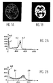
- Figures 1A and 1B show two examples of images of a human brain;
- Figure 1A shows an axial section of the brain on MRI and the figure 1B shows an axial section of the brain in SPECT.
- These two images, of different modalities, are linked by a rigid transformation.
- Some of these registration methods are based on the spatial or frequency moments of images and determine the location, orientation or size change of an object in a picture. However, even if, in theory, a image is completely described by all its moments, in practical, high order moments are very sensitive noise and edge distortion.
- registration methods use a higher order information from clues visuals extracted from the images. For example, some of these methods consist in isolating, in the two images, points in direct correspondence. These points are either selected manually in each of the two images, either selected using markers designating, before the acquisition, certain points of benchmark from which the registration of the images. The distance between these points is then gradually reduced, by a registration algorithm based, for example, on a regression following least squares, on a breakdown into values singular in 3D, or on other methods known mathematics.
- information extracted from two images must necessarily represent the same structures (elements of objects contained in images), especially for multimodal images. These methods can then be unstable towards modification of this extracted information, which leads to geometric errors.
- extraction information is generally unstable and difficult, a change of configuration that can change completely the solution found.
- a change of threshold changes, in most cases, the structure of the object extracted from the image.
- phase shift registration method is deduced from the properties of the Fourier transform with respect to translation in the spatial domain (DIGITAL IMAGE PROCESSING, WK PRATT, Ed. Wiley Interscience, page 12).
- a method based on the maximizing mutual information allows a registration of multimodal images.
- One such method is described in the document “multimodality Image Registration by Maximization of mutual information ”de MAES, CALLIGNON et al., IEEE Transactions on medical imaging, vol. 16, April 1997, or in the document “Multi-modal volume registration by maximization of mutual information ", from WELLS et al., Medical Image Analysis, vol. 1, No. 1, p. 35-51, February 1996.
- This method has the disadvantage of require a large number of calculations, as well as a optimization algorithm to converge to the solution, hence computing time problems non-constant, and a risk of convergence towards a local minimum, which corresponds to bad solution.
- the object of the invention is precisely to remedy the disadvantages of the methods mentioned previously.
- This method consists in decomposing each of the images into spatial components representative of the grayscale distribution of the image, at apply the phase registration method on the components for matching components of an image with those of the other image, at sum all the results of the implementation match and detect, in the image resulting from this sum, the maximum gray level that defines the transformation between the two initial images.
- steps 16b to 16e consist of apply a simple Fourier transform.
- the stages 16b and 16e consist in applying the transform of Fourier-Mellin to a group consisting of a rotation and a change of scale and to associate it with a measurement of Haar to determine the parameters of rotation and the change of scale.
- the steps 16b to 16th consist in applying a transform of Simple Fourier associated with a rotation of the images.
- the method of the invention is to extend the phase difference images by a zero-padding method in order to increase the precision of the parameters determined in step E20.
- the method of the invention includes the different stages represented in the functional diagram of figure 3.
- the first step of the process, referenced 10, is a step of obtaining the two images I1 and I2, each of these images being a set of pixels.
- These two images I1 and I2 can be obtained from an identical image acquisition device, or from image acquisition devices different ; it is also possible that one of these images either a simulated image or a model image, such as a card in the case, for example, of registration of a satellite image with a map geographical.
- Step 13 of the process of the invention consists in segmenting each of the images into different components and to deduce, for each image, a set of images segmented according to at least one of these components.
- Segmentation can be done by depending on the grayscale of the images, or depending on texture, color, etc., images or again automatically, as described in the document "Parameter Estimation and Tissue Segmentation from Multipsectral Images ”, IEEE Trans. on Medical Imaging, Z. LIANG and Al, volume 13, no. 3, September 1994, pages 441 - 449.
- this segmentation is carried out in depending on the grayscale of the images.
- this step 13 consists of a step 12 of choice of gray level thresholds for each of images I1 and I2.
- this step consists of choose, independently for each image, a number of gray level thresholds. So, n1 greyscale thresholds will be chosen to define image I1, and n2 gray level thresholds will be chosen to define the image I2.
- the level thresholds grayscale of an image are chosen so that the pixels of this image between two thresholds be as representative as possible of the structure contained in the image, i.e. the object shown in the picture.
- gray level thresholds is performed, in particular, by building, for each images, a grayscale histogram of the image ; this histogram is a function which, for each grayscale in the image indicates the number of pixels that have this gray level. From the grayscale histogram of an image, one or several thresholds are chosen so as to allow identifying structures, such as the object by compared to the background of the image.
- Grayscale pixels between 0 and S are representative of the background of the image and the pixels of gray levels between S and M are representative of the object in the image.
- FIG. 2A and 2B there is shown the grayscale histograms of the images of Figures 1A and 1B, respectively.
- the thresholds chosen can be a0, a1, a2 and a3 and for the histogram of figure 2B, the thresholds can be b0, b1 and b2.
- the process of the invention continues with a step 16 of calculating the registration buffer by the phase for each pair of components of the images I1 and I2.
- a registration buffer a memory area multidirectional sampled, where is accumulated the essential of the possible solutions.
- all pairs of possible components are determined in this step 16a.
- This step 16 corresponds, in the case from a simple translation, to the application of the method phase shifting, described previously.
- the transformed applied is therefore the Fourier transform.
- the transform to apply is a transform which allows to pass each component of the space domain couple at a dual frequency domain.
- the method of the invention then comprises a step 18 of summing all the images of offset contained in the registration buffers for determine, in a global buffer, an image of total offset.
- the method of the invention comprises a step 20 of finding the maximum value, in the total offset image; this maximum value corresponds to the maximum gray level in the image, which gives the translation in x and in y of the image I1 in the frame of reference I2.
- This search for the maximum in the total registration image is, in fact, to calculate the geometric transformation which allows to superimpose the images I1 and I2 in the same frame, this geometric transformation being determined from pixel coordinates of maximum value.
- the total registration image is of dimension 2 and the coordinates of the maximum represent in x the translation in the direction X, defined in pixels, and in y the translation according to the Y direction, also defined in pixels.
- the process of the invention can be implemented works for more complex transformations than translation between two images.
- it can be used for a rotating application; in this case, the Fourier transform of step 16 is replaced by a Fourier-Mellin transformation, which allows to calculate the scale and the rotation between two images.
- a rotation of images (one of the two images) before phase can be performed; in this case, we apply different rotations to the image I1 and we do a registration between each image I1 rotated and image I2 by the phase registration method, described above, which generates a registration buffer for each rotation.
- the final transformation is found by seeking the maximum of a set of registration buffers. The buffer which contains this maximum, then defines the rotation between images, while translation is defined by the position of the maximum in this buffer.
- the process of the invention can also be applied to elastic transformations, which allow to model the deformations of an object.
- the elastic movement is modeled by the composition of a set of rigid transformations local.
- the calculation of each local transformation rigid is then done by the registration method by the phase in translation and, possibly, in rotation.
- Geometric transformation such as determined in step 20 of the process of the invention, can be used directly or indirectly. Indeed, the geometric transformation determined by the process can directly constitute the information sought by the user, namely the movement of an object by compared to a camera. It can also be applied to one of the images I1 or I2, so that present the two images I1 and I2 in the same frame geometric, to facilitate use or the interpretation of the images by the user, which is the case in the examples of brain images of Figures 1A and 1B.
- the processing was done for trips rigid, integer multiples of the pixel size.
- the precision obtained with the process, as just described is of the order of length of the pixel.
- This precision can nevertheless be improved using a method of oversampling such as the so-called "Zero-padding transformation”.
- This method of zero-padding transformation involves enlarging the image phase differences (step 16d) with 0 to outside, which makes it possible to obtain, at the exit of the computation of the inverse Fourier transform, an image which has a lower resolution than the original images, that is to say an image whose precision is lower to the pixel size.
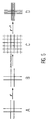
- FIG. 5 there is shown overall the four steps of this method of zero-padding for an image representing a kind of double cross.
- Part A of this figure 5 represents an image before the Fourier transform
- part B represents the same image after a transformation by the Fourier transform
- Part C represents the image of phase differences on which we have added 0 around the double cross (object of the image)
- part D represents the final image obtained after transformation by the transform of Reverse Fourier.
- the accuracy, for this example has been improved approximately by a factor of 3.
- This method of the invention has the advantage to be non-interactive, which allows a computing time almost constant.
- this process does not require by no means, for steps 12 and 14, to have a particularly good segmentation quality, the registration result obtained being almost independent the quality of the segmentation, i.e. the decomposition of images into components. Indeed, a slightly different choice of thresholds changes the components extracted, but does not influence the result significantly, the estimate of the rigid transformation remaining almost identical.
Abstract
Description
L'invention concerne un procédé de recalage de deux images différentes d'un même objet et, en particulier, de deux images multimodales. Elle trouve des applications dans tous les domaines nécessitant une superposition d'images différentes d'un même objet et, en particulier, dans les domaines du contrôle non-destructif et de l'imagerie médicale.The invention relates to a registration method of two different images of the same object and, in in particular, of two multimodal images. She finds applications in all areas requiring superimposition of different images of the same object and, in particular in the areas of control non-destructive and medical imagery.
L'exploitation d'images nécessite souvent une superposition d'images. Bien que ces images sont généralement représentatives d'un même objet, elles ne sont pas superposables directement pour différentes raisons : elles peuvent avoir été prises à des instants différents ou par des systèmes d'acquisition différents.The exploitation of images often requires an overlay of images. Although these images are generally representative of the same object, they do not are not directly stackable for different reasons: they may have been taken at times different or by acquisition systems different.
En outre, même pour des images ayant des structures géométriques équivalentes (c'est-à-dire des images qui contiennent des éléments d'objets identiques), la distribution des niveaux de gris sur les deux images à superposer peut différer d'une image à l'autre ; on parle alors d'images multimodales.In addition, even for images with equivalent geometric structures (i.e. images that contain elements of objects identical), the distribution of the gray levels on the two images to be superimposed may differ from one image to the other ; we then speak of multimodal images.
Pour être exploitables simultanément, et en particulier superposables, de telles images doivent, au préalable, être mises en correspondance, c'est-à-dire être mises dans un repère géométrique commun aux deux images ; il est donc nécessaire de déterminer la transformation géométrique qui permet de représenter une des images dans le repère géométrique de l'autre image ; on parle alors de recalage d'images.To be usable simultaneously, and in particularly superimposable, such images must, at the be matched, i.e. be put in a geometric coordinate system common to both pictures; therefore it is necessary to determine the geometric transformation which allows to represent one of the images in the geometric coordinate system of the other picture ; this is called image registration.
En particulier, le recalage d'images est nécessaire en imagerie médicale pour permettre l'observation d'une même partie du corps humain dont une image est obtenue, par exemple, par un scanner à rayonnements X et une autre image est obtenue, par exemple, par IRM (imagerie par résonance magnétique) ou encore par tomographie d'émission à photon unique (SPECT).In particular, the registration of images is necessary in medical imaging to allow the observation of the same part of the human body whose an image is obtained, for example, by a scanner with X-rays and another image is obtained, by for example, by MRI (magnetic resonance imaging) or again by single photon emission tomography (SPECT).
Les figures 1A et 1B représentent deux exemples d'images d'un cerveau humain ; la figure 1A montre une coupe axiale du cerveau en IRM et la figure 1B montre une coupe axiale du cerveau en SPECT. Ces deux images, de modalités différentes, sont liées par une transformation rigide.Figures 1A and 1B show two examples of images of a human brain; Figure 1A shows an axial section of the brain on MRI and the figure 1B shows an axial section of the brain in SPECT. These two images, of different modalities, are linked by a rigid transformation.
Actuellement, plusieurs méthodes sont connues pour recaler deux images du type décrit précédemment.Currently, several methods are known to register two images of the type described previously.
Certaines méthodes font l'hypothèse que les distributions de niveaux de gris sont équivalentes pour les deux images à recaler ; les niveaux de gris des images sont alors utilisés directement pour calculer le décalage entre les deux images. Parmi ces méthodes, il y a la méthode d'intercorrélation qui consiste à déterminer le maximum d'une fonction de la transformation ou bien d'un produit dans le domaine fréquentiel. Some methods assume that gray level distributions are equivalent for the two images to be readjusted; the grayscale of images are then used directly to calculate the offset between the two images. Among these methods, there is the cross-correlation method which consists of determine the maximum of a function of the transformation or of a product in the field frequency.
Cependant, ces méthodes présentent un inconvénient majeur qui réside dans le fait que le bruit dans les images ainsi que certaines distorsions locales peuvent cacher le pic de corrélation, ce qui fausse les résultats du recalage.However, these methods present a major drawback which resides in the fact that the noise in images and some distortions local can hide the correlation peak, which distorts the readjustment results.
De plus, du fait même de l'hypothèse faite sur les niveaux de gris, ces méthodes ne peuvent être applicables pour des images multimodales.In addition, by the very fact of the hypothesis made on grayscale, these methods cannot be applicable for multimodal images.
Certaines de ces méthodes de recalage sont basées sur les moments spatiaux ou fréquentiels des images et permettent de déterminer la localisation, l'orientation ou le changement de taille d'un objet dans une image. Cependant, même si, en théorie, une image est complètement décrite par tous ses moments, en pratique, les moments d'ordre élevé sont très sensibles aux bruits et aux distorsions de contours.Some of these registration methods are based on the spatial or frequency moments of images and determine the location, orientation or size change of an object in a picture. However, even if, in theory, a image is completely described by all its moments, in practical, high order moments are very sensitive noise and edge distortion.
Dans le cas où les images sont très bruitées, ou si les niveaux de gris des images diffèrent trop, ou encore si les images sont dans des modalités différentes, alors l'algorithme de recalage de ces méthodes est faussé et le recalage des images est incorrect.In case the images are very noisy, or if the grayscale of the images differ too much, or if the images are in different modalities, then the registration algorithm of these methods is distorted and the registration of the images is incorrect.
D'autres méthodes de recalage sont également connues. Ces méthodes utilisent une information d'ordre supérieur à partir d'indices visuels extraits des images. Par exemple, certaines de ces méthodes consistent à isoler, dans les deux images, des points en correspondance directe. Ces points sont soit sélectionnés manuellement dans chacune des deux images, soit sélectionnés au moyen de marqueurs désignant, avant l'acquisition, certains points de repère à partir desquels se fera le recalage des images. La distance entre ces points est ensuite diminuée progressivement, par un algorithme de recalage basé, par exemple, sur une régression suivant les moindres carrés, sur une décomposition en valeurs singulières en 3D, ou sur d'autres méthodes mathématiques connues.Other registration methods are also known. These methods use a higher order information from clues visuals extracted from the images. For example, some of these methods consist in isolating, in the two images, points in direct correspondence. These points are either selected manually in each of the two images, either selected using markers designating, before the acquisition, certain points of benchmark from which the registration of the images. The distance between these points is then gradually reduced, by a registration algorithm based, for example, on a regression following least squares, on a breakdown into values singular in 3D, or on other methods known mathematics.
Ces méthodes peuvent être appliquées pour des contours, des surfaces ou tout autre ensemble de points.These methods can be applied to contours, surfaces or any other set of points.
Elles présentent l'avantage de permettre la manipulation d'une quantité d'informations réduite par rapport à celle des méthodes décrites précédemment, tout en tenant compte de l'introduction d'une information supérieure. Cependant, elles ont l'inconvénient d'être dépendantes de la façon dont sont mises en évidence les informations.They have the advantage of allowing the manipulation of a reduced amount of information by compared to that of the methods described above, while taking into account the introduction of a superior information. However, they have the downside of being dependent on how are highlighted information.
De plus, les informations extraites de deux images doivent nécessairement représenter les mêmes structures (éléments d'objets contenues dans les images), en particulier pour les images multimodales. Ces méthodes peuvent alors être instables vis-à-vis de modification de ces informations extraites, ce qui conduit à des erreurs géométriques.In addition, information extracted from two images must necessarily represent the same structures (elements of objects contained in images), especially for multimodal images. These methods can then be unstable towards modification of this extracted information, which leads to geometric errors.
En particulier, pour des images acquises (c'est-à-dire non simulées), l'extraction d'informations est généralement instable et difficile, un changement de paramétrage pouvant changer complètement la solution trouvée. Par exemple, un changement de seuil modifie, dans la plupart des cas, la structure de l'objet extrait de l'image.In particular, for acquired images (i.e. not simulated), extraction information is generally unstable and difficult, a change of configuration that can change completely the solution found. For example, a change of threshold changes, in most cases, the structure of the object extracted from the image.
Une autre méthode connue est la méthode de
recalage en translation par la phase, qui se déduit des
propriétés de la transformée de Fourier vis-à-vis de la
translation dans le domaine spatial (DIGITAL IMAGE
PROCESSING, W. K. PRATT, Ed. Wiley Interscience,
page 12). Dans cette méthode, on appelle,
respectivement, u(
Par transformée de Fourier, où 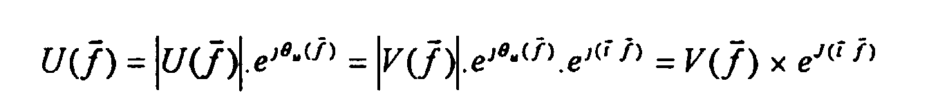

Cependant, cette méthode est limitée tout d'abord, à des images de même modalités et ensuite à des transformations de types translations.However, this method is limited while first, to images of the same modalities and then to translation-type transformations.
Par ailleurs, une méthode basée sur la maximisation d'informations mutuelles permet un recalage d'images multimodales. Une telle méthode est décrite dans le document « multimodality Image Registration by Maximization of mutual information » de MAES, CALLIGNON et Al., IEEE Transactions on medical imaging, vol. 16, Avril 1997, ou dans le document « Multi-modal volume registration by maximization of mutual information », de WELLS et Al., Medical Image Analysis, vol. 1, n° 1, p. 35-51, Février 1996.In addition, a method based on the maximizing mutual information allows a registration of multimodal images. One such method is described in the document “multimodality Image Registration by Maximization of mutual information ”de MAES, CALLIGNON et al., IEEE Transactions on medical imaging, vol. 16, April 1997, or in the document "Multi-modal volume registration by maximization of mutual information ", from WELLS et al., Medical Image Analysis, vol. 1, No. 1, p. 35-51, February 1996.
Cette méthode a l'inconvénient de nécessiter un nombre de calculs important, ainsi qu'un algorithme d'optimisation pour converger vers la solution, d'où des problèmes de temps de calcul non-constant, et un risque de convergence vers un minimum local, ce qui correspond à une mauvaise solution.This method has the disadvantage of require a large number of calculations, as well as a optimization algorithm to converge to the solution, hence computing time problems non-constant, and a risk of convergence towards a local minimum, which corresponds to bad solution.
L'invention a justement pour but de remédier aux inconvénients des méthodes citées précédemment. A cette fin, elle propose un procédé pour recaler, en un temps quasiment constant, deux images différentes qui peuvent être des images multimodales. Cette méthode consiste à décomposer chacune des images en composantes spatiales représentatives de la distribution des niveaux de gris de l'image, à appliquer la méthode de recalage par la phase sur les composantes pour une mise en correspondance des composantes d'une image avec celles de l'autre image, à sommer l'ensemble des résultats de la mise en correspondance et à détecter, dans l'image résultant de cette somme, le niveau de gris maximum qui définit la transformation entre les deux images initiales.The object of the invention is precisely to remedy the disadvantages of the methods mentioned previously. To this end, it proposes a method for readjust, in almost constant time, two images which can be multimodal images. This method consists in decomposing each of the images into spatial components representative of the grayscale distribution of the image, at apply the phase registration method on the components for matching components of an image with those of the other image, at sum all the results of the implementation match and detect, in the image resulting from this sum, the maximum gray level that defines the transformation between the two initial images.
De façon plus précise, l'invention concerne
un procédé de détermination d'une transformation
géométrique entre deux images I1 et I2 différentes,
représentatives toutes deux d'un même objet, en vue de
les superposer. Ce procédé se caractérise par le fait
qu'il consiste à :
Selon un premier mode de réalisation de l'invention, dans lequel la transformation géométrique est une translation, les étapes 16b à 16e consistent à appliquer une transformée de Fourier simple.According to a first embodiment of the invention, in which the geometric transformation is a translation, steps 16b to 16e consist of apply a simple Fourier transform.
Selon un second mode de réalisation de l'invention, où la transformation géométrique est une rotation associée à un changement d'échelle, les étapes 16b et 16e consistent à appliquer la transformée de Fourier-Mellin à un groupe constitué d'une rotation et d'un changement d'échelle et à l'associer à une mesure de Haar pour déterminer les paramètres de la rotation et du changement d'échelle.According to a second embodiment of the invention, where the geometric transformation is a rotation associated with a change of scale, the stages 16b and 16e consist in applying the transform of Fourier-Mellin to a group consisting of a rotation and a change of scale and to associate it with a measurement of Haar to determine the parameters of rotation and the change of scale.
Selon un troisième mode de réalisation de l'invention, dans lequel la transformation géométrique est une translation associée à une rotation, les étapes 16b à 16e consistent à appliquer une transformée de Fourier simple associée à une rotation des images.According to a third embodiment of the invention, in which the geometric transformation is a translation associated with a rotation, the steps 16b to 16th consist in applying a transform of Simple Fourier associated with a rotation of the images.
Dans ce mode de réalisation :
- on applique des recalages successifs aux deux images en procédant à des rotations successives sur l'une des deux images et en les recalant l'une par rapport à l'autre, à chaque fois, par la méthode de la phase en translation (cf premier mode de réalisation) ;
- pour une translation et pour chaque recalage, on détermine une image de recalage ;
- on recherche le pixel de valeur maximum dans l'ensemle des images de décalage obtenues pour l'ensemble des rotations (la translation est déterminée par la position du pixel maximum de l'image qui le contient), l'image de décalage contenant ce maximum étant associée à une rotation. Cette rotation et la translation définissent la transformation géométrique.
- successive readjustments are applied to the two images by carrying out successive rotations on one of the two images and by resetting them one with respect to the other, each time, by the method of the phase in translation (cf. first embodiment);
- for a translation and for each registration, a registration image is determined;
- we search for the pixel of maximum value in the set of offset images obtained for all rotations (the translation is determined by the position of the maximum pixel of the image that contains it), the offset image containing this maximum being associated with a rotation. This rotation and the translation define the geometric transformation.
Avantageusement, le procédé de l'invention consiste à étendre les images de différences de phases par une méthode de zéro-padding afin d'augmenter la précision des paramètres déterminés à l'étape E20.Advantageously, the method of the invention is to extend the phase difference images by a zero-padding method in order to increase the precision of the parameters determined in step E20.
Selon un mode de réalisation de
l'invention, la segmentation E13 des images est
effectuée en fonction des niveaux de gris des images,
cette segmentation consistant à :
- Les figures 1A et 1B représentent deux exemples d'images d'un cerveau humain réalisées par des moyens d'acquisition différents ;Figures 1A and 1B show two examples of images of a human brain made by different means of acquisition;
- les figures 2A et 2B représentent les histogrammes des niveaux de gris des images des figures 1A et 1B ;Figures 2A and 2B show the grayscale histograms of figure images 1A and 1B;
- la figure 3 représente le diagramme fonctionnel du procédé de l'invention ; Figure 3 shows the diagram functional of the method of the invention;
- la figure 4 représente un exemple d'histogramme et de choix des seuils de niveaux de gris ; etFigure 4 shows an example of histogram and choice of the thresholds of levels of Grey ; and
- la figure 5 représente schématiquement un exemple d'image obtenue dans le cas où on utilise la méthode « zéro-padding ».FIG. 5 schematically represents a example of image obtained in the case where the "zero-padding" method.
L'invention concerne un procédé destiné à recaler deux images d'un même objet, réalisées au moyen de deux systèmes d'acquisition différents ou au moyen d'un seul système d'acquisition mais à deux moments différents. Le recalage de ces deux images se fait en déterminant la transformation géométrique permettant de mettre les deux images dans un même repère de façon à les superposer. Cette transformation géométrique est déterminée en :
- décomposant chacune des images en une pluralité de composantes spatiales représentatives de la distribution des niveaux de gris de chaque image ;
- mettant en correspondance, par la phase, une composante de chaque image pour former des couples de composantes ; et en
- sommant l'ensemble des résultats de la mise en correspondance, puis en détectant le niveau de gris maximum, dans l'image résultant de cette somme.
- decomposing each of the images into a plurality of spatial components representative of the distribution of the gray levels of each image;
- matching, by phase, a component of each image to form pairs of components; and in
- summing all the results of the matching, then detecting the maximum gray level, in the image resulting from this sum.
Plus précisément, le procédé de l'invention comporte les différentes étapes représentées dans le diagramme fonctionnel de la figure 3.More specifically, the method of the invention includes the different stages represented in the functional diagram of figure 3.
La première étape du procédé, référencée 10, est une étape d'obtention des deux images I1 et I2, chacune de ces images étant un ensemble de pixels. Ces deux images I1 et I2 peuvent être obtenues à partir d'un dispositif d'acquisition d'images identiques, ou à partir de dispositifs d'acquisition d'images différents ; il est possible également que l'une de ces images soit une image simulée ou une image modèle, telle qu'une carte dans le cas, par exemple, du recalage d'une image satellite avec une carte géographique.The first step of the process, referenced 10, is a step of obtaining the two images I1 and I2, each of these images being a set of pixels. These two images I1 and I2 can be obtained from an identical image acquisition device, or from image acquisition devices different ; it is also possible that one of these images either a simulated image or a model image, such as a card in the case, for example, of registration of a satellite image with a map geographical.
L'étape 13 du procédé de l'invention
consiste à segmenter chacune des images en différentes
composantes et à en déduire, pour chaque image, un
ensemble d'images segmentées en fonction d'au moins une
de ces composantes.
La segmentation peut être réalisée en
fonction des niveaux de gris des images, ou bien
suivant la texture, la couleur, etc., des images ou
encore automatiquement, comme décrit dans le document
« Parameter Estimation and Tissue Segmentation from
Multipsectral Images », IEEE Trans. on Medical Imaging,
Z. LIANG et Al, volume 13, no. 3, September 1994, pages
441 - 449.Segmentation can be done by
depending on the grayscale of the images, or
depending on texture, color, etc., images or
again automatically, as described in the document
"Parameter Estimation and Tissue Segmentation from
Multipsectral Images ”, IEEE Trans. on Medical Imaging,
Z. LIANG and Al,
Selon un mode de réalisation préféré de
l'invention, cette segmentation est effectuée en
fonction des niveaux de gris des images. En
particulier, cette étape 13 consiste en une étape 12 de
choix des seuils de niveaux de gris pour chacune des
images I1 et I2. Autrement dit, cette étape consiste à
choisir, indépendamment pour chacune des images, un
certain nombre de seuils de niveaux de gris. Ainsi, n1
seuils de niveaux de gris seront choisis pour définir
l'image I1, et n2 seuils de niveaux de gris seront
choisis pour définir l'image I2. Les seuils de niveaux
de gris d'une image sont choisis de façon à ce que les
pixels de cette image compris entre deux seuils soient
les plus représentatifs possible de la structure
contenue dans l'image, c'est-à-dire de l'objet
représenté sur l'image.According to a preferred embodiment of
the invention, this segmentation is carried out in
depending on the grayscale of the images. In
particular, this
Ce choix des seuils de niveaux de gris est effectué, en particulier, en construisant, pour chacune des images, un histogramme des niveaux de gris de l'image ; cet histogramme est une fonction qui, pour chaque niveau de gris de l'image, indique le nombre de pixels qui ont ce niveau de gris. A partir de l'histogramme des niveaux de gris d'une image, un ou plusieurs seuils sont choisis de façon à permettre l'identification des structures, telles que l'objet par rapport au fond de l'image.This choice of gray level thresholds is performed, in particular, by building, for each images, a grayscale histogram of the image ; this histogram is a function which, for each grayscale in the image indicates the number of pixels that have this gray level. From the grayscale histogram of an image, one or several thresholds are chosen so as to allow identifying structures, such as the object by compared to the background of the image.
Sur la figure 4, on a représenté un exemple d'histogramme des niveaux de gris d'une image représentant un objet clair sur un fond sombre. Les niveaux de gris d'une image étant fonction du nombre de pixels (ou points images) ayant ce niveau de gris, l'histogramme de la figure 4 montre un premier pic représentant le fond de l'image et un second pic représentant l'objet lui-même. Cet histogramme a donc deux modes. Dans cet exemple, un seuil unique est choisi pour décomposer l'image ; ce seuil a pour valeur, le milieu des deux modes (chaque mode correspondant à un pic), référencé S sur la figure 4. Ce seuil S est associé à deux seuils naturels O et M qui sont, respectivement, les valeurs minimum et maximum des niveaux de gris de l'histogramme. Les trois seuils utilisés ici sont alors :
- la valeur minimum, en particulier 0 ;
- le seuil S correspondant au milieu des deux modes ;
- la valeur maximum sur l'image, appelée M.
- the minimum value, in particular 0;
- the threshold S corresponding to the middle of the two modes;
- the maximum value on the image, called M.
Les pixels de niveaux de gris entre 0 et S sont représentatifs du fond de l'image et les pixels de niveaux de gris entre S et M sont représentatifs de l'objet dans l'image.Grayscale pixels between 0 and S are representative of the background of the image and the pixels of gray levels between S and M are representative of the object in the image.
La définition de seuils peut se faire par plusieurs méthodes différentes :
- une approche manuelle dans laquelle l'opérateur choisit le seuil, par exemple de façon itérative ;
- une méthode dans laquelle les seuils sont, a priori, connus pour les classes d'images traitées, c'est-à-dire, par exemple, lorsque les valeurs des images correspondent à des grandeurs physiques, comme c'est le cas pour les scanners X ;
- des méthodes de calculs pour calculer automatiquement le nombre de seuils à utiliser, ainsi que les valeurs des seuils : par exemple, à partir d'études des modes de l'histogramme, ou à partir d'un algorithme itératif. Le seuil est alors défini comme la valeur du niveau de gris où les deux Gaussiennes les plus proches s'intercroisent.
- a manual approach in which the operator chooses the threshold, for example iteratively;
- a method in which the thresholds are, a priori, known for the classes of images processed, that is to say, for example, when the values of the images correspond to physical quantities, as is the case for the X scanners;
- calculation methods to automatically calculate the number of thresholds to be used, as well as the threshold values: for example, from studies of histogram modes, or from an iterative algorithm. The threshold is then defined as the gray level value where the two closest Gaussians intersect.
Cette méthode de détermination du nombre de
seuils par modélisation d'un histogramme sous forme
d'une somme de gaussienne est décrite par Z. LIANG, J.
R. Mac FALL, D. P. HARRINGTON, 1994, dans « Parameter
Estimation and Tissue Segmentation from Multispectral
Images », dans IEEE Trans. On Medical Imaginig,
volume 13, n° 3, Septembre 1994, p. 441-449. This method of determining the number of
thresholds by modeling a histogram in the form
of a Gaussian sum is described by Z. LIANG, J.
R. Mac FALL, D. P. HARRINGTON, 1994, in “Parameter
Estimation and Tissue Segmentation from Multispectral
Images ”, in IEEE Trans. On Medical Imaginig,
Sur les figures 2A et 2B, on a représenté les histogrammes des niveaux de gris des images des figures 1A et 1B, respectivement. Pour l'histogramme de la figure 2A, les seuils choisis peuvent être a0, a1, a2 et a3 et pour l'histogramme de la figure 2B, les seuils peuvent être b0, b1 et b2.In Figures 2A and 2B, there is shown the grayscale histograms of the images of Figures 1A and 1B, respectively. For the histogram of FIG. 2A, the thresholds chosen can be a0, a1, a2 and a3 and for the histogram of figure 2B, the thresholds can be b0, b1 and b2.
La troisième étape du procédé de l'invention, référencée 14, est une étape de décomposition des images I1 et I2 en différentes composantes, établies à partir des seuils déterminés à l'étape 12. En particulier, chaque image I1 et I2 est décomposée en un ensemble de composantes (si le nombre de seuils choisis pour une image est n, alors le nombre de composantes de cette image est n-1). Chacune de ces composantes est définie par rapport à un seuil haut et un seuil bas. On obtient ainsi, pour chaque image I1 et I2, un ensemble d'images seuillées. Les valeurs des pixels de ces images seuillées sont définies de la façon suivante :
- une constante, par exemple 0, si le niveau de gris du pixel dans l'image initiale n'est pas dans l'intervalle (seuil bas, seuil haut) ; et
- FONC(niveau-gris-pixel) si le niveau de gris du pixel dans l'image initiale est dans l'intervalle [seuil bas, seuil haut]. Cette fonction FONC peut être une fonction quelconque non nulle et, en particulier, la fonction de valeur constante 1, ou la fonction identité.
- a constant, for example 0, if the gray level of the pixel in the initial image is not in the interval (low threshold, high threshold); and
- FONC (gray-level-pixel) if the gray level of the pixel in the initial image is in the interval [low threshold, high threshold]. This FONC function can be any non-zero function and, in particular, the
constant value function 1, or the identity function.
Le procédé de l'invention se poursuit par
une étape 16 de calcul du buffer de recalage par la
phase pour chaque couple de composantes des images I1
et I2. On appelle buffer de recalage, une zone mémoire
multidirectionnelle échantillonnée, où est accumulé
l'essentiel des solutions possibles.The process of the invention continues with
a
Cette étape 16 consiste à :
Selon un mode de réalisation de l'invention, tous les couples de composantes possibles sont déterminés à cette étape 16a.According to an embodiment of the invention, all pairs of possible components are determined in this step 16a.
Selon un autre mode de réalisation, un seul
couple de composante est déterminé à l'étape 16a ; les
traitements suivants de l'étape 16 sont alors appliqués
à ce couple ; ensuite un nouveau couple de composantes
sera déterminé, auquel sera appliqué le traitement des
étapes 16a à 16f, et ainsi de suite.
Cette étape 16 correspond, dans le cas
d'une simple translation, à l'application de la méthode
de recalage en translation par la phase, décrite
précédemment.This
Il est à noter que l'on a décrit cette
étape 16 pour le cas d'une translation ; la transformée
appliquée est donc la transformée de Fourier.
Toutefois, d'une façon plus générale, la transformée à
appliquer est une transformée qui permet de passer
chaque composante du couple du domaine spatial à un
domaine dual fréquentiel.It should be noted that this has been described
Le procédé de l'invention comporte ensuite
une étape 18 de sommation de l'ensemble des images de
décalage contenues dans les buffers de recalage pour
déterminer, dans un buffer global, une image de
décalage total.The method of the invention then comprises
a
Enfin, le procédé de l'invention comporte
une étape 20 de recherche de la valeur maximum, dans
l'image de décalage total ; cette valeur maximum
correspond au niveau de gris maximum dans l'image, qui
donne la translation en x et en y de l'image I1 dans le
repère de l'image I2. Cette recherche du maximum dans
l'image de recalage total consiste, en fait, à calculer
la transformation géométrique qui permet de superposer
les images I1 et I2 dans un même repère, cette
transformation géométrique étant déterminée à partir
des coordonnées du pixel de valeur maximum.Finally, the method of the invention comprises
a
Dans le cas classique où la recherche de décalage est une recherche de translation sur des images bidimensionnelles, l'image de recalage total est de dimension 2 et les coordonnées du maximum représentent en x la translation selon la direction X, définie en pixels, et en y la translation selon la direction Y, définie également en pixels. In the classic case where the search for shift is a search for translation on two-dimensional images, the total registration image is of dimension 2 and the coordinates of the maximum represent in x the translation in the direction X, defined in pixels, and in y the translation according to the Y direction, also defined in pixels.
Selon un mode de réalisation de
l'invention, le procédé de l'invention peut être mis en
oeuvre pour des transformations plus complexes qu'une
translation entre deux images. En particulier, elle
peut être utilisée pour une application en rotation ;
dans ce cas, la transformée de Fourier de l'étape 16
est remplacée par une transformation de Fourier-Mellin,
ce qui permet de calculer l'échelle et la rotation
entre deux images.According to an embodiment of
the invention, the process of the invention can be implemented
works for more complex transformations than
translation between two images. In particular, it
can be used for a rotating application;
in this case, the Fourier transform of
En outre, une rotation d'images (une des deux images) avant phase peut être effectuée ; dans ce cas, on applique différentes rotations à l'image I1 et on fait un recalage entre chaque image I1 tournée et l'image I2 par la méthode de recalage par la phase, décrite précédemment, ce qui permet de générer un buffer de recalage pour chaque rotation. La transformation finale est trouvée en cherchant le maximum d'un ensemble de buffers de recalage. Le buffer qui contient ce maximum, définit alors la rotation entre les images, tandis que la translation est définie par la position du maximum dans ce buffer.In addition, a rotation of images (one of the two images) before phase can be performed; in this case, we apply different rotations to the image I1 and we do a registration between each image I1 rotated and image I2 by the phase registration method, described above, which generates a registration buffer for each rotation. The final transformation is found by seeking the maximum of a set of registration buffers. The buffer which contains this maximum, then defines the rotation between images, while translation is defined by the position of the maximum in this buffer.
Le procédé de l'invention peut également être appliqué à des transformations élastiques, qui permettent de modéliser les déformations d'un objet. Dans ce cas, le mouvement élastique est modélisé par la composition d'un ensemble de transformations rigides locales. Le calcul de chaque transformation locale rigide se fait alors par la méthode de recalage par la phase en translation et, éventuellement, en rotation.The process of the invention can also be applied to elastic transformations, which allow to model the deformations of an object. In this case, the elastic movement is modeled by the composition of a set of rigid transformations local. The calculation of each local transformation rigid is then done by the registration method by the phase in translation and, possibly, in rotation.
La transformation géométrique, telle que
déterminée à l'étape 20 du procédé de l'invention, peut
être utilisée directement ou indirectement. En effet,
la transformation géométrique déterminée par le procédé
peut constituer directement l'information recherchée
par l'utilisateur, à savoir le mouvement d'un objet par
rapport à une caméra. Elle peut, par ailleurs, être
appliquée à l'une des images I1 ou I2, de façon à
présenter les deux images I1 et I2 dans un même repère
géométrique, afin de faciliter l'utilisation ou
l'interprétation des images par l'utilisateur, ce qui
est le cas dans les exemples d'images de cerveau des
figures 1A et 1B.Geometric transformation, such as
determined in
On notera que dans toute la description du procédé de l'invention, qui vient d'être donnée, le traitement a été effectué pour des déplacements rigides, multiples entiers de la taille des pixels. Autrement dit, la précision obtenue avec le procédé, tel qu'il vient d'être décrit, est de l'ordre de la longueur du pixel. Cette précision peut néanmoins être améliorée en utilisant une méthode de suréchantillonnage telle que la méthode dite de « transformation zéro-padding ». Cette méthode de transformation zéro-padding consiste à agrandir l'image de différences de phases (étape 16d) avec des 0 à l'extérieur, ce qui permet d'obtenir, à la sortie du calcul de la transformée inverse de Fourier, une image qui a une résolution inférieure aux images de départ, c'est-à-dire une image dont la précision est inférieure à la taille du pixel.Note that throughout the description of the process of the invention, which has just been given, the processing was done for trips rigid, integer multiples of the pixel size. In other words, the precision obtained with the process, as just described, is of the order of length of the pixel. This precision can nevertheless be improved using a method of oversampling such as the so-called "Zero-padding transformation". This method of zero-padding transformation involves enlarging the image phase differences (step 16d) with 0 to outside, which makes it possible to obtain, at the exit of the computation of the inverse Fourier transform, an image which has a lower resolution than the original images, that is to say an image whose precision is lower to the pixel size.
Sur la figure 5, on a représenté globalement les quatre étapes de cette méthode de zéro-padding pour une image représentant une sorte de double croix. La partie A de cette figure 5 représente une image avant la transformée de Fourier ; la partie B représente la même image après une transformation par la transformée de Fourier ; la partie C représente l'image de différences de phases sur laquelle on a rajouté des 0 tout autour de la double croix (objet de l'image) ; et la partie D représente l'image finale obtenue après transformation par la transformée de Fourier inverse. Comme on le voit sur cette partie D de la figure 5, la précision, pour cet exemple, a été améliorée approximativement d'un coefficient 3.In Figure 5, there is shown overall the four steps of this method of zero-padding for an image representing a kind of double cross. Part A of this figure 5 represents an image before the Fourier transform; part B represents the same image after a transformation by the Fourier transform; Part C represents the image of phase differences on which we have added 0 around the double cross (object of the image) ; and part D represents the final image obtained after transformation by the transform of Reverse Fourier. As seen on this part D of Figure 5, the accuracy, for this example, has been improved approximately by a factor of 3.
Il est à noter que le procédé de l'invention qui vient d'être décrit peut être appliqué aussi bien à des images bidimensionnelles qu'à des images tridimensionnelles.It should be noted that the process of the invention which has just been described can be applied both two-dimensional images and three-dimensional images.
Ce procédé de l'invention a l'avantage
d'être non-intératif, ce qui permet un temps de calcul
à peu près constant. De plus, ce procédé ne nécessite
nullement, pour les étapes 12 et 14, d'avoir une
qualité de segmentation particulièrement bonne, le
résultat du recalage obtenu étant quasiment indépendant
de la qualité de la segmentation, c'est-à-dire de la
décomposition des images en composantes. En effet, un
choix un peu différent des seuils fait évoluer les
composantes extraites, mais n'influence pas le résultat
final de façon sensible, l'estimation de la
transformation rigide demeurant quasiment identique.This method of the invention has the advantage
to be non-interactive, which allows a computing time
almost constant. In addition, this process does not require
by no means, for
Claims (6)
Applications Claiming Priority (2)
| Application Number | Priority Date | Filing Date | Title |
|---|---|---|---|
| FR9804560 | 1998-04-10 | ||
| FR9804560A FR2777374B1 (en) | 1998-04-10 | 1998-04-10 | METHOD OF RECORDING TWO DIFFERENT IMAGES OF THE SAME OBJECT |
Publications (1)
| Publication Number | Publication Date |
|---|---|
| EP0949588A1 true EP0949588A1 (en) | 1999-10-13 |
Family
ID=9525152
Family Applications (1)
| Application Number | Title | Priority Date | Filing Date |
|---|---|---|---|
| EP99400832A Withdrawn EP0949588A1 (en) | 1998-04-10 | 1999-04-06 | Registration process of two different images of the same object |
Country Status (3)
| Country | Link |
|---|---|
| US (1) | US6343143B1 (en) |
| EP (1) | EP0949588A1 (en) |
| FR (1) | FR2777374B1 (en) |
Cited By (1)
| Publication number | Priority date | Publication date | Assignee | Title |
|---|---|---|---|---|
| WO2002097535A2 (en) * | 2001-05-30 | 2002-12-05 | Nptest, Inc. | Sub-resolution alignment of images |
Families Citing this family (25)
| Publication number | Priority date | Publication date | Assignee | Title |
|---|---|---|---|---|
| CA2475896C (en) * | 2002-02-11 | 2011-08-23 | Visx, Inc. | Determining relative positional and rotational offsets |
| KR20040008067A (en) * | 2002-07-15 | 2004-01-28 | 삼성전자주식회사 | Image enhancing circuit using corelation between frames and method therefor |
| US6891934B1 (en) * | 2002-08-20 | 2005-05-10 | Bellsouth Intellectual Property Corporation | IP handset-based voice mail notification |
| US7403646B2 (en) * | 2002-10-24 | 2008-07-22 | Canon Kabushiki Kaisha | Image processing apparatus, image processing method, program, and recording medium for generating a difference image from a first radiographic image and second radiographic image |
| AU2003903511A0 (en) * | 2003-07-08 | 2003-07-24 | Canon Kabushiki Kaisha | Image registration method improvement |
| US7417981B2 (en) * | 2003-10-15 | 2008-08-26 | Vonage Holdings Corp. | Method and apparatus for enhanced Internet Telephony |
| JP4439882B2 (en) * | 2003-11-14 | 2010-03-24 | キヤノン株式会社 | Radiation image processing apparatus and processing method |
| US7263243B2 (en) * | 2003-12-29 | 2007-08-28 | Carestream Health, Inc. | Method of image registration using mutual information |
| US7386111B2 (en) * | 2004-02-10 | 2008-06-10 | Vonage Network Inc. | Method and apparatus for placing a long distance call based on a virtual phone number |
| JP2005312776A (en) * | 2004-04-30 | 2005-11-10 | Canon Inc | Radiograph acquisition device |
| US7639896B2 (en) * | 2004-08-09 | 2009-12-29 | Carestream Health, Inc. | Multimodal image registration using compound mutual information |
| US7653264B2 (en) * | 2005-03-04 | 2010-01-26 | The Regents Of The University Of Michigan | Method of determining alignment of images in high dimensional feature space |
| US20060210040A1 (en) * | 2005-03-16 | 2006-09-21 | Jeffrey Citron | Transfer identification software enabling electronic communication system |
| US20060210036A1 (en) * | 2005-03-16 | 2006-09-21 | Jeffrey Citron | System for effecting a telephone call over a computer network without alphanumeric keypad operation |
| US8683044B2 (en) | 2005-03-16 | 2014-03-25 | Vonage Network Llc | Third party call control application program interface |
| CA2622732A1 (en) * | 2005-10-13 | 2007-04-26 | Vonage Holdings Corp. | Method and system for detecting a change in device attachment |
| US8306202B2 (en) * | 2005-11-09 | 2012-11-06 | Vonage Network Llc | Method and system for customized caller identification |
| CN101385317A (en) * | 2006-02-01 | 2009-03-11 | 沃纳格控股公司 | Method and apparatus for communicating a status of a device in a packet-based communication network |
| US8917717B2 (en) * | 2007-02-13 | 2014-12-23 | Vonage Network Llc | Method and system for multi-modal communications |
| AU2007217346B2 (en) * | 2006-02-27 | 2011-07-28 | Vonage Holdings Corp. | Automatic device configuration |
| US8712139B2 (en) * | 2008-03-21 | 2014-04-29 | General Electric Company | Methods and systems for automated segmentation of dense cell populations |
| US20100130969A1 (en) * | 2008-11-25 | 2010-05-27 | Apogen Technologies, Inc. | System and method for dermatological treatment |
| US8611692B2 (en) | 2011-09-26 | 2013-12-17 | Northrop Grumman Systems Corporation | Automated image registration with varied amounts of a priori information using a minimum entropy method |
| GB2555675B (en) * | 2016-08-05 | 2019-05-08 | Secr Defence | Method and apparatus for generating an enhanced digital image of a physical object or environment |
| EP3874406A4 (en) | 2018-11-01 | 2022-08-10 | Intelligent Imaging Innovations, Inc. | Image processing using registration by localized cross correlation (lxcor) |
Citations (1)
| Publication number | Priority date | Publication date | Assignee | Title |
|---|---|---|---|---|
| US5295200A (en) * | 1991-01-09 | 1994-03-15 | Board Of Regents, The University Of Texas System | Method and apparatus for determining the alignment of an object |
Family Cites Families (4)
| Publication number | Priority date | Publication date | Assignee | Title |
|---|---|---|---|---|
| US5581638A (en) * | 1993-07-26 | 1996-12-03 | E-Systems, Inc. | Method for autonomous image registration |
| US5709206A (en) * | 1995-11-27 | 1998-01-20 | Teboul; Michel | Imaging system for breast sonography |
| DE19613342A1 (en) * | 1996-04-03 | 1997-10-09 | Philips Patentverwaltung | Automatic image evaluation process |
| US5850486A (en) * | 1996-04-29 | 1998-12-15 | The Mclean Hospital Corporation | Registration of image data |
-
1998
- 1998-04-10 FR FR9804560A patent/FR2777374B1/en not_active Expired - Fee Related
-
1999
- 1999-04-01 US US09/283,868 patent/US6343143B1/en not_active Expired - Fee Related
- 1999-04-06 EP EP99400832A patent/EP0949588A1/en not_active Withdrawn
Patent Citations (1)
| Publication number | Priority date | Publication date | Assignee | Title |
|---|---|---|---|---|
| US5295200A (en) * | 1991-01-09 | 1994-03-15 | Board Of Regents, The University Of Texas System | Method and apparatus for determining the alignment of an object |
Non-Patent Citations (1)
| Title |
|---|
| RIZZO G ET AL: "MULTIMODALITY BIOMEDICAL IMAGE INTEGRATION: USE OF A CROSS-CORRELATION TECHNIQUE", PROCEEDINGS OF THE ANNUAL INTERNATIONAL CONFERENCE OF THE ENGINEERI IN MEDICINE AND BIOLOGY SOCIETY, ORLANDO, OCT. 31 - NOV. 3, 1991, vol. 1, no. CONF. 13, 31 October 1991 (1991-10-31), NAGEL J;SMITH W M, pages 219 - 220, XP000346248 * |
Cited By (4)
| Publication number | Priority date | Publication date | Assignee | Title |
|---|---|---|---|---|
| WO2002097535A2 (en) * | 2001-05-30 | 2002-12-05 | Nptest, Inc. | Sub-resolution alignment of images |
| WO2002097535A3 (en) * | 2001-05-30 | 2003-11-27 | Nptest Inc | Sub-resolution alignment of images |
| US6848087B2 (en) | 2001-05-30 | 2005-01-25 | Credence Systems Corporation | Sub-resolution alignment of images |
| US7409653B2 (en) | 2001-05-30 | 2008-08-05 | Dcg Systems, Inc. | Sub-resolution alignment of images |
Also Published As
| Publication number | Publication date |
|---|---|
| FR2777374B1 (en) | 2000-05-12 |
| FR2777374A1 (en) | 1999-10-15 |
| US6343143B1 (en) | 2002-01-29 |
Similar Documents
| Publication | Publication Date | Title |
|---|---|---|
| EP0949588A1 (en) | Registration process of two different images of the same object | |
| EP0840252B1 (en) | Digital image-processing method for the automatic extraction of ribbon-like objects | |
| Pham et al. | Robust fusion of irregularly sampled data using adaptive normalized convolution | |
| EP0927405B1 (en) | Image processing electronic device for detecting dimensional variations | |
| Lagendijk et al. | Basic methods for image restoration and identification | |
| Li et al. | Multifocus image fusion based on redundant wavelet transform | |
| Xu et al. | SAR image denoising via clustering-based principal component analysis | |
| EP0945830B1 (en) | Image processing method including multidimensional image segmentation stages and medical imaging apparatus using the same | |
| Ali et al. | Guided image filtering in shape-from-focus: A comparative analysis | |
| EP1749278A2 (en) | Image data processing method by reducing image noise, and camera integrating means for implementing said method | |
| EP0732668A1 (en) | Contour extraction method using multi-fractal analysis | |
| Wu et al. | Blind blur assessment for vision-based applications | |
| Anitha et al. | Restoration of X-ray fluorescence images of hidden paintings | |
| Yang et al. | Different focus points images fusion based on wavelet decomposition | |
| EP2212733B1 (en) | Method and device for the reconstruction of the shape of an object from a sequence of sectional images of said object | |
| EP2294552B1 (en) | Improved device for processing images | |
| Šroubek et al. | Fusion of blurred images | |
| Chen et al. | Unified framework for the joint super-resolution and registration of multiangle multi/hyperspectral remote sensing images | |
| Reddy et al. | Multispectral image denoising methods: A literature review | |
| Bull et al. | Perceptual improvements for super-resolution of satellite imagery | |
| Deng et al. | Texture edge-guided depth recovery for structured light-based depth sensor | |
| Kang et al. | Multisensor super resolution using directionally adaptive regularization for UAV images | |
| WO2019081587A1 (en) | Image restoration method | |
| Kaur et al. | Hand Gesture Image Enhancement for Improved Recognition and Subsequent Analysis | |
| Kim et al. | A majorize-minimize approach for high-quality depth upsampling |
Legal Events
| Date | Code | Title | Description |
|---|---|---|---|
| PUAI | Public reference made under article 153(3) epc to a published international application that has entered the european phase |
Free format text: ORIGINAL CODE: 0009012 |
|
| AK | Designated contracting states |
Kind code of ref document: A1 Designated state(s): DE GB IT |
|
| AX | Request for extension of the european patent |
Free format text: AL;LT;LV;MK;RO;SI |
|
| 17P | Request for examination filed |
Effective date: 20000327 |
|
| AKX | Designation fees paid |
Free format text: DE GB IT |
|
| RBV | Designated contracting states (corrected) |
Designated state(s): DE GB IT |
|
| STAA | Information on the status of an ep patent application or granted ep patent |
Free format text: STATUS: THE APPLICATION IS DEEMED TO BE WITHDRAWN |
|
| 18D | Application deemed to be withdrawn |
Effective date: 20021104 |