EP0953847A1 - Capacitor - Google Patents
Capacitor Download PDFInfo
- Publication number
- EP0953847A1 EP0953847A1 EP98966979A EP98966979A EP0953847A1 EP 0953847 A1 EP0953847 A1 EP 0953847A1 EP 98966979 A EP98966979 A EP 98966979A EP 98966979 A EP98966979 A EP 98966979A EP 0953847 A1 EP0953847 A1 EP 0953847A1
- Authority
- EP
- European Patent Office
- Prior art keywords
- sintered
- capacitor
- niobium
- niobium nitride
- electrode
- Prior art date
- Legal status (The legal status is an assumption and is not a legal conclusion. Google has not performed a legal analysis and makes no representation as to the accuracy of the status listed.)
- Granted
Links
Images
Classifications
-
- H—ELECTRICITY
- H01—ELECTRIC ELEMENTS
- H01G—CAPACITORS; CAPACITORS, RECTIFIERS, DETECTORS, SWITCHING DEVICES OR LIGHT-SENSITIVE DEVICES, OF THE ELECTROLYTIC TYPE
- H01G9/00—Electrolytic capacitors, rectifiers, detectors, switching devices, light-sensitive or temperature-sensitive devices; Processes of their manufacture
- H01G9/004—Details
- H01G9/04—Electrodes or formation of dielectric layers thereon
- H01G9/042—Electrodes or formation of dielectric layers thereon characterised by the material
Definitions
- This invention relates to a novel capacitor. More particularly, it relates to a capacitor which is inexpensive and exhibits good leak current characteristics, and a capacitor which has a large capacitance, especially a large capacitance per unit weight at a high frequency, and exhibits good leak characteristics.
- capacitors made of a sintered metal those which are composed of sintered aluminum, tantalum and alloys thereof are known. These capacitors have widely used in various fields. For example, for a capacitor used in a smoothing circuit for obtaining a direct current from an alternating current, it is desired that the capacitor possesses a low impedance and a large capacitance at a high frequency for suppressing the occurrence of spike-shaped voltage and enhancing the efficiency of conversion to a direct current.
- sintered metals used as a capacitor electrode have problems. Namely, sintered aluminum has poor environmental characteristics such as moisture resistance and chemical characteristics, and sintered tantalum is expensive.
- Sintered niobium is also known as a material used for a capacitor electrode, and not possessing the problems encountered with sintered aluminum and tantalum, but, it has another problem that oxygen adsorbed on its surface influences dielectrics as mentioned below, and thus, the leak current characteristics are not satisfactory and it is of poor practical use.
- the volume of a sintered metal substrate made of, for example, tantalum or aluminum should be increased.
- the increase in volume of the sintered metal substrate is inconsistent with a requirement of miniaturisation of a capacitor.
- tantalum gives a relatively satisfactory for the requirements of an enhanced capacitance at a high frequency and a miniaturization of a capacitor, but, it is still not completely satisfactory for these requirements.
- a tantalum oxide is used as a dielectric substance for a capacitor with an electrode composed of sintered tantalum bodies.
- the capacitor can be more miniaturized.
- the material having a large dielectric constant there can be mentioned titanium oxide and niobium oxide. But, these materials exhibit poor leak current (hereinafter abbreviated to "LC") characteristics.
- the inventors have found, first, that sintered bodies of niobium nitride are advantageous in that the amount Of oxygen deposited on the surface thereof is minor and the leak current characteristics of the capacitor are satisfactory, and secondly, that the above-mentioned problem as for LC characteristics of a capacitor with niobium oxide dielectrics is due to the fact that oxygen deposited on the surface of sintered bodies influences the dielectric substance. Based on these findings, the inventors have completed the present invention.
- the inventors have further found that, if the electrode other than the electrode composed of sintered niobium nitride bodies is made of at least one compound selected from organic semiconductors and inorganic semiconductors, which do not have a capability of supplying oxygen to an undue extent, a capacitor having a large capacitance at a high frequency can be obtained. Further, if, as the organic semiconductor or the inorganic semiconductor, those which have an electrical conductivity of 10 -2 S ⁇ cm -1 to 10 3 S ⁇ cm -1 are used, a capacitor having a more reduced impedance can be obtained.
- a capacitor comprising a pair of electrodes and a dielectric substance intervening between the electrodes, characterized in that one of the electrodes is composed of sintered niobium nitride.
- the dielectric substance of the above-mentioned capacitor is preferably made of niobium oxide, more preferably made of niobium oxide prepared by electrolytic oxidation of the sintered niobium nitride.
- the other of the two electrodes is preferably made of at least one ingredient selected from electrolytes, organic semiconductors and inorganic semiconductors, more preferably at least one ingredient selected from organic semiconductors and inorganic conductors, which have an electrical conductivity of from 10 -2 S ⁇ cm -1 to 10 3 S ⁇ cm -1.
- the niobium nitride constituting one of the electrodes in the capacitor of the invention is made by partially nitrifying metallic niobium.
- niobium nitride of a powdery form is made by nitrifying the surfaces of particles of powdery niobium in a nitrogen gas atmosphere.
- the amount of nitrogen bound to the niobium is in the range of from 10 to 200,000 ppm by weight, preferably 100 to 50,000 ppm by weight.
- the temperature employed is not higher than 2,000°C and the time employed is in several tens of hours.
- the thus-obtained powdery niobium nitride has a shape approximately similar to that of the powdery niobium used as the raw material.
- powdery niobium mass obtained by pulverizing a niobium lump is used as a raw material
- powdery niobium nitride having various shapes which are peculiar to pulverized mass is obtained.
- powdery niobium in the form of a secondary particle which is prepared by reducing potassium fluoroniobate to give a finely divided particles, and granulating the finely divided particles into secondary particles, then, powdery niobium nitride similar to the secondary particles is obtained. Further, for example, if powdery niobium having an average particle diameter of from 0.5 ⁇ m to 100 ⁇ m is used, powdery niobium nitride having a similar average particle diameter is obtained.
- the sintered niobium nitride is obtained by sintering, for example, powdery niobium nitride at a high temperature in vacuo.
- powdery niobium nitride is press-molded and then the molded product is allowed to stand at a temperature of 1,000 to 2,000°C and a pressure of 10 -1 to 10 -6 Torr for several minutes to several hours to give a sintered niobium nitride. If the degree of vacuum is insufficient at sintering, air is entrapped in the powdery material during sintering, oxidation occurs simultaneously with nitrification with the result that the capacitor with the niobium nitride electrode has a poor performance.
- a suitable sintering temperature varies depending upon the particle diameter of the powdery niobium nitride, and, the smaller the particle diameter, the lower the sintering temperature.
- the dielectric substance used in the capacitor of the invention there can be mentioned, for example, tantalum oxide, niobium oxide, polymeric substances and ceramic compounds.
- tantalum oxide can be prepared by depositing a tantalum-containing complex such as, for example, an alkoxy complex or an acetylacetonato complex on an electrode, and then, subjecting the deposit to hydrolysis and/or pyrolysis.
- the niobium oxide can be prepared by chemically converting a niobium nitride electrode into niobium oxide in an electrolyte, or by depositing a niobium-containing complex such as, for example, an alkoxy complex or an acetylacetonato complex on an electrode, and then, subjecting the deposit to hydrolysis and/or pyrolysis.
- a niobium-containing complex such as, for example, an alkoxy complex or an acetylacetonato complex
- a niobium oxide dielectrics can be formed on the surface of niobium nitride electrode by converting a niobium nitride electrode into niobium oxide in an electrolyte or subjecting a niobium-containing complex on a niobium nitride electrode to hydrolysis and/or pyrolysis.
- the conversion of niobium nitride into niobium oxide in an electrolyte can be effected usually by using an aqueous protonic acid, for example, an aqueous 0.1% phosphoric acid solution or sulfuric acid solution.
- the capacitor of the invention is an electrolytic capacitor with a positive electrode composed of niobium nitride.
- the niobium nitride has theoretically no polarity and can be used either as a positive electrode or a negative electrode.
- the polymeric substance dielectrics can be prepared by, as described in Japanese Unexamined Patent Publication No. H7-63045, a process wherein a gaseous or liquid monomer is introduced in voids or pores within metal, followed by polymerization; a process wherein a solution of a polymeric substance in a suitable solvent is introduced; and a process wherein a molten polymeric substance is introduced.
- a fluororesin an alkyd resin, an acrylic resin, a polyester resin such as polyethylene terephthalate, a vinyl resin, a xylylene resin and a phenol resin.
- the dielectric substance composed of a ceramic compound can be prepared by a process for producing a compound with perovskite structure on a surface of metal having voids or pores, as described in Japanese Unexamined Patent Publication No. H7-85461.
- a compound with peroviskite structure there can be mentioned BaTiO 3 , SrTiO 3 , MgTiO 3 and BaSnO 3 .
- the electrode other than the niobium nitride electrode of the capacitor of the invention is not particularly limited, and can be composed of at least one ingredient selected from electrolytes well known in an aluminum electrolytic capacitor industry, organic semiconductors and inorganic semiconductors.
- electrolytes there can be mentioned a mixed dimethylformamide/ethylene glycol liquid containing 5% by weight of isobutyltripropylammonium borontetrafluoride, and a mixed propylene carbonate/ethylene glycol liquid containing 7% by weight of tetraethylammonium borontetrafluoride.
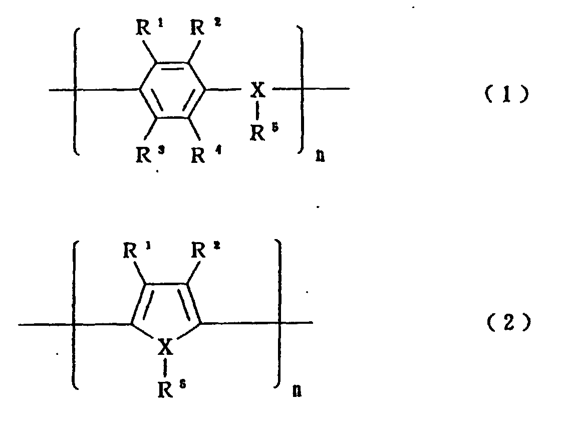
- organic semiconductors there can be mentioned an organic semiconductor composed of benzopyroline tetramer and chloranil, an organic semiconductor predominantly comprised of tetrathiotetracene, an organic semiconductor predominantly comprised of tetracyano-quinodimethane, and organic semiconductors predominantly comprised of electrically conductive polymers represented by the following formula (1) or (2), which are doped with a dopant.
- R 1 , R 2 , R 3 and R 4 independently represents hydrogen, an alkyl group having 1 to 6 carbon atoms or an alkoxy group having 1 to 6 carbon atoms
- X represents an oxygen, sulfur or nitrogen atom
- R 5 represents only when X is a nitrogen atom
- R 1 and R 2 may form together a ring
- R 3 and R 4 also may form together a ring.
- the electrically conductive polymers of formulae (1) and (2) there can be mentioned polyaniline, polyoxyphenylene, polyphenylene sulfide, polythiophene, polyfuran, polypyrrole and polymethylpyrrole.
- inorganic semiconductors predominantly comprised of lead dioxide or manganese dioxide, and inorganic semiconductors composed of triiron tetraoxide. These semiconductors may be used either alone or as a mixture of at least two thereof.
- the structure of the capacitor of the invention may be those which have heretofore been employed, provided that the capacitor comprises a pair of electrodes and a dielectric intervening between the electrodes.
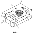
- One specific example of the capacitor of the invention is illustrated in Fig. 1, wherein a sintered niobium nitride 1 composed of a plurality of sintered niobium nitride bodies is placed as an electrode and on which niobium oxide dielectric layers have been formed by chemically converting the surfaces of the sintered niobium nitride bodies into niobium oxide in an electrolyte, or by subjecting a niobium-containing complex to hydrolysis and/or pyrolysis to produce niobium oxide on the surfaces of the sintered niobium nitride bodies.
- the other electrode is formed on the dielectric layer.
- a carbon paste 2 and a silver paste 3 are formed in this order on the other electrode, and then, the thus-prepared laminated product is encapsulated with a sealing material such as epoxy resin to form a capacitor.
- the capacitor is provided with a niobium lead 4 which has been sintered in integrated with the sintered niobium nitride bodies or which has been welded to the niobium nitride sintered bodies.
- the capacitor is assembled together with a positive electrode lead 5 and a negative electrode lead 6 and the assembly is enclosed by an outer resin covering 7.
- the capacitor provided with the niobium lead 4, illustrated in Fig. 1, is a rectangular parallelopiped, but, its shape is not particularly limited thereto and may be, for example, cylindrical.
- Powdery niobium having an average particle diameter of 10 to 40 ⁇ m was treated at 400°C in a nitrogen atmosphere to give powdery niobium nitride.
- the amount of nitrogen bound to niobium by nitrification was about 2,000 ppm by weight.
- the powdery niobium nitride was sintered at 1,500°C in vacuo to give sintered niobium nitride bodies having a diameter of 10 mm and a thickness of about 1 mm, and containing pores having an average diameter of 3 ⁇ m with a porosity of 45%.
- the sintered niobium nitride bodies were treated in an aqueous phosphoric acid solution at a voltage of 20 V to form a niobium oxide dielectric layer on the surface of each sintered body.
- Example No. Other electrode and electrical conductivity(S ⁇ cm -1 ) Electrode forming method Example 1 Chloranil complex of tetrathiotetracene 2 x 10 0 Repeat of immersion in solution of the compound described in the left column, and drying Example 2 Isoquinoline complex of tetracyanoquinodimethane 3 x 10 0 Repeat of immersion in solution of the compound described in the left column, and drying Example 3 Dope of polyaniline in toluensulfonic 3 x 10 1 Repeat of oxidation reaction in aniline solution Example 4 Dope of polypyrrole in toluenesulfonic acid 5 x 10 1 Repeat of oxidation rection in pyrrole solution Example 5 Dope of polythiophene in toluenesulfonic acid 4 x 10 1 Repeat of oxidation reaction in thiophene solution Example 6 Mixture of lead dioxide and lead sul
- Powdery niobium nitride having an average particle diameter of 40 to 80 ⁇ m and a bound nitrogen content of about 10,000 ppm by weight was sintered at 1,600°C in vacuo to give sintered niobium nitride bodies having a diameter of 10 mm and a thickness of 1 mm, and containing pores having an average diameter of 7 ⁇ m with a porosity of 55%.
- the sintered niobium nitride bodies were immersed in a bath of pentaethyl niobate liquid, and thereafter, the sintered niobium nitride bodies taken out from the bath were maintained at 85°C in a steam and then dried at 350°C whereby a dielectric layer composed of niobium oxide was formed on the sintered niobium nitride bodies.
- Example 8 Each of chloranil complex of tetrathiotetracene (Example 8) and a mixture of lead acetate and lead sulfate (Example 9) for forming an electrode other than the electrode composed of the sintered niobium nitride bodies was deposited on a plurality of the dielectric layer-formed sintered niobium nitride bodies by the same procedures employed in Example 1 and Example 6, respectively. Further, a carbon paste and then a silver paste were laminated in this order on the dielectric layer-formed sintered niobium nitride bodies. Then the laminated product was encapsulated with an epoxy resin to give a capacitor. The properties of the capacitor were evaluated. The results are shown in Table 2.
- Powdery tantalum having an average particle diameter of 10 to 40 ⁇ m was sintered at 1,500°C in vacuo to give sintered tantalum bodies having a diameter of 10 mm and a thickness of about 1 mm, and containing pores having an average diameter of 3 ⁇ m with a porosity of 45%.
- the sintered tantalum bodies were treated in an aqueous phosphoric acid solution at a voltage of 20 V to form a tantalum oxide dielectric layer on the surface of each sintered body.
- each of chloranil complex of tetrathiotetracene (Comparative Example 1) and a mixture of lead acetate and lead sulfate (Comparative Example 2) for forming an electrode other than the electrode composed of the sintered tantalum bodies was deposited on a plurality of the dielectric layer-formed sintered tantalum bodies by the same procedures employed in Example 1 and Example 6, respectively. Further, a carbon paste and then a silver paste were laminated in this order on the dielectric layer-formed sintered tantalum bodies, and then, the thus-laminated product was encapsulated with an epoxy resin by the same procedures as employed in the above-mentioned Examples to give a capacitor. The properties of the capacitor were evaluated. The results are shown in Table 2.
- Example 1 The procedures employed in Example 1 and Example 6 were repeated wherein the powdery niobium was not nitrified and was sintered to give sintered niobium bodies, and capacitors were made from the sintered niobium bodies. The properties of the capacitors were evaluated. The results are shown in Table 2. Capacitance (100 kHz) ⁇ F LC(4V) ⁇ A Example 1 55 0.9 Example 2 50 0.8 Example 3 60 1.2 Example 4 60 1.0 Example 5 55 1.2 Example 6 62 0.8 Example 7 60 1.0 Example 8 40 0.3 Example 9 40 0.3 Comparative Example 1 24 0.02 Comparative Example 2 26 0.04 Comparative Example 3 54 14 Comparative Example 4 57 18
- Example 2 The same sintered niobium nitride bodies as prepared in Example 1 were immersed in a bath of pentaethyl tantalate liquid, and thereafter, the sintered niobium nitride bodies taken out from the bath were maintained at 85°C in a steam and then dried at 450°C whereby a dielectric layer composed of tantalum oxide was formed on the sintered niobium nitride bodies.
- the electrolyte-applied sintered niobium nitride bodies were charged in a can, and the can was sealed to give a capacitor.
- Example 10 The procedures employed in Example 10 were repeated to make a capacitor wherein sintered niobium bodies were used instead of the sintered niobium nitride bodies with all other conditions remaining the same. The properties of the capacitor were evaluated. The results are shown in Table 3.
- Example 3 By the same procedures as employed in Example 1, sintered niobium nitride bodies were made and then niobium oxide dielectric layers were formed on the sintered niobium nitride bodies. An electrolyte was applied to the dielectric layer-formed sintered niobium nitride bodies, and the electrolyte-applied product was charged in a can and the can was sealed to give a capacitor by the same procedures as described in Example 10. The properties of the capacitor were evaluated. The results are shown in Table 3.
- Example 11 The procedures as employed in Example 11 were repeated to make a capacitor wherein sintered niobium bodies were used instead of the sintered niobium nitride bodies with all other conditions remaining the same. The properties of the capacitor were evaluated. The results are shown in Table 3. LC(4V) ⁇ A Example 10 0.3 Example 11 0.4 Comparative Example 5 9 Comparative Example 6 10
- a carbon paste and then a silver paste were laminated in this order on the dielectric layer-formed sintered niobium nitride bodies, and then, the thus-laminated product was encapsulated with an epoxy resin by the same procedures as employed in the above-mentioned Examples to give a capacitor.
- the triiron tetraoxide used had an electrical conductivity of 10 -3 S ⁇ cm -1 .
- the properties of the capacitor were evaluated. The results are shown in Table 4.
- Example 12 The procedures as employed in Example 12 were repeated to make a capacitor wherein sintered niobium bodies were used instead of the sintered niobium nitride bodies with all other conditions remaining the same. The properties of the capacitor were evaluated. The results are shown in Table 4. Capacitance (100 kHz) ⁇ F LC(4V) ⁇ A Example 12 38 0.7 Comparative Example 7 38 16
- the capacitor of the invention with an electrode composed of sintered niobium nitride bodies exhibits excellent environmental stability and leak current (LC) characteristics.
- the capacitor having an electrode composed of sintered niobium nitride bodies and the other electrode composed of at least one ingredient selected from organic semiconductors and inorganic semiconductors, and having a niobium oxide dielectric intervening between the two electrodes has an enhanced capacitance per unit weight at a high frequency as well as excellent leak current (LC) characteristics. Therefore, the capacitor of the invention is suitable for a smoothing circuit of a power source.
Abstract
Description
| Example No. | Other electrode and electrical conductivity(S·cm-1) | Electrode forming method |
| Example 1 | Chloranil complex of tetrathiotetracene 2 x 100 | Repeat of immersion in solution of the compound described in the left column, and drying |
| Example 2 | Isoquinoline complex of tetracyanoquinodimethane 3 x 100 | Repeat of immersion in solution of the compound described in the left column, and drying |
| Example 3 | Dope of polyaniline in toluensulfonic 3 x 101 | Repeat of oxidation reaction in aniline solution |
| Example 4 | Dope of polypyrrole in toluenesulfonic acid 5 x 101 | Repeat of oxidation rection in pyrrole solution |
| Example 5 | Dope of polythiophene in toluenesulfonic acid 4 x 101 | Repeat of oxidation reaction in thiophene solution |
| Example 6 | Mixture of lead dioxide and lead sulfate (lead dioxide 97 wt%) 5 x 101 | Repeat of oxidation reaction of lead acetate solution |
| Example 7 | Mixture of manganese dioxide and lead dioxide (lead dioxide 95 wt%) 5 x 101 | Thermal decomposition of manganese nitrate (250°C twice), then repeat of oxidation reaction of lead acetate solution |
| Capacitance (100 kHz) µF | LC(4V) µA | |
| Example 1 | 55 | 0.9 |
| Example 2 | 50 | 0.8 |
| Example 3 | 60 | 1.2 |
| Example 4 | 60 | 1.0 |
| Example 5 | 55 | 1.2 |
| Example 6 | 62 | 0.8 |
| Example 7 | 60 | 1.0 |
| Example 8 | 40 | 0.3 |
| Example 9 | 40 | 0.3 |
| Comparative Example 1 | 24 | 0.02 |
| Comparative Example 2 | 26 | 0.04 |
| Comparative Example 3 | 54 | 14 |
| Comparative Example 4 | 57 | 18 |
| LC(4V) µA | |
| Example 10 | 0.3 |
| Example 11 | 0.4 |
| Comparative Example 5 | 9 |
| Comparative Example 6 | 10 |
| Capacitance (100 kHz) µF | LC(4V) µA | |
| Example 12 | 38 | 0.7 |
| Comparative Example 7 | 38 | 16 |
Claims (6)
- A capacitor comprising a pair of electrodes and a dielectric substance intervening between the electrodes, characterized in that one of the electrodes is composed of sintered niobium nitride.
- The capacitor according to claim 1, wherein the content of bound nitrogen in the sintered niobium nitride is in the range of 10 to 200,000 ppm by weight.
- The capacitor according to claim 1 or 2, wherein the dielectric substance is composed of niobium oxide.
- The capacitor according to claim 3, wherein the dielectric substance composed of niobium oxide is formed on the electrode composed of sintered niobium nitride by conversion-treating the electrode composed of sintered niobium nitride in an electrolyte, or subjecting a niobium-containing complex to hydrolysis and/or pyrolysis on the electrode composed of sintered niobium nitride.
- The capacitor according to any of claims 1 to 4, wherein the electrode other than the electrode composed of sintered niobium nitride is at least one ingredient selected from electrolytes, organic semiconductors and inorganic semiconductors.
- The capacitor according to any of claims 1 to 4, wherein the electrode other than the electrode composed of sintered niobium nitride is at least one ingredient selected from organic semiconductors and inorganic semiconductors, which have an electrical conductivity of 10-2 S·cm-1 to 103 S·cm-1.
Applications Claiming Priority (3)
| Application Number | Priority Date | Filing Date | Title |
|---|---|---|---|
| JP4565097 | 1997-02-28 | ||
| JP04565097A JP3254163B2 (en) | 1997-02-28 | 1997-02-28 | Capacitor |
| PCT/JP1998/000823 WO1998038660A1 (en) | 1997-02-28 | 1998-02-27 | Capacitor |
Publications (3)
| Publication Number | Publication Date |
|---|---|
| EP0953847A1 true EP0953847A1 (en) | 1999-11-03 |
| EP0953847A4 EP0953847A4 (en) | 2001-02-07 |
| EP0953847B1 EP0953847B1 (en) | 2005-04-27 |
Family
ID=12725261
Family Applications (1)
| Application Number | Title | Priority Date | Filing Date |
|---|---|---|---|
| EP98966979A Revoked EP0953847B1 (en) | 1997-02-28 | 1998-02-27 | Capacitor with an electrode composed of a sintered body of partially nitrided niobium powder |
Country Status (7)
| Country | Link |
|---|---|
| US (5) | US6115235A (en) |
| EP (1) | EP0953847B1 (en) |
| JP (1) | JP3254163B2 (en) |
| CN (1) | CN1192404C (en) |
| DE (1) | DE69829945T2 (en) |
| HK (1) | HK1022948A1 (en) |
| WO (1) | WO1998038660A1 (en) |
Cited By (17)
| Publication number | Priority date | Publication date | Assignee | Title |
|---|---|---|---|---|
| EP1158552A1 (en) * | 1998-12-15 | 2001-11-28 | Showa Denko Kabushiki Kaisha | Niobium capacitor and method of manufacture thereof |
| US6338816B1 (en) | 1998-05-04 | 2002-01-15 | Cabot Corporation | Nitrided niobium powders and niobium electrolytic capacitors |
| WO2002004152A1 (en) * | 2000-07-12 | 2002-01-17 | Cabot Supermetals K.K. | Metallic powder containing nitrogen, process for producing the same, and porous sinter and solid electrolytic capacitor both obtained from the same |
| WO2002045106A2 (en) * | 2000-11-30 | 2002-06-06 | Showa Denko K.K. | Powder for capacitor, sintered body thereof and capacitor using the sintered body |
| US6402066B1 (en) | 1999-03-19 | 2002-06-11 | Cabot Corporation | Method of making niobium and other metal powders |
| EP1227508A1 (en) * | 2001-01-22 | 2002-07-31 | Kawatetsu Mining Co., LTD. | Niobium powder and anode for solid electrolytic capacitors made therefrom |
| EP1264321A1 (en) * | 2000-11-30 | 2002-12-11 | Showa Denko K.K. | Niobium powder for capacitor, sintered body thereof and capacitor using the sintered body |
| EP1275124A1 (en) * | 2000-12-01 | 2003-01-15 | Showa Denko K.K. | Niobium powder for capacitor, sintered body thereof and capacitor using the sintered body |
| WO2003015961A1 (en) * | 2001-08-15 | 2003-02-27 | Cabot Super Metals K. K. | Nitrogen-containing metal powder and method for producing the same, and porous sintered product and solid electrolytic capacitor using the same |
| EP1374262A1 (en) * | 1999-02-08 | 2004-01-02 | H.C. Starck,Inc. | Capacitor substrates made of refractory metal nitrides |
| US6679934B2 (en) | 2000-03-01 | 2004-01-20 | Cabot Corporation | Nitrided valve metals and processes for making the same |
| US6702869B2 (en) | 1999-05-12 | 2004-03-09 | Cabot Corporation | High capacitance niobium powders and electrolytic capacitor anodes |
| US7037355B2 (en) * | 2000-04-21 | 2006-05-02 | Showa Denko Kabushiki Kaisha | Niobium powder for capacitor, sintered body using the powder and capacitor using the same |
| WO2006128687A2 (en) * | 2005-06-03 | 2006-12-07 | H.C. Starck Gmbh | Niobium suboxides |
| CN100401436C (en) * | 2000-11-30 | 2008-07-09 | 昭和电工株式会社 | Powder for capacitor, sintered body thereof and capacitor using sintered body |
| WO2008137401A1 (en) * | 2007-05-02 | 2008-11-13 | Micron Technology, Inc | Constructions and devices including tantalum oxide layers on niobium nitride and methods for producing the same |
| US7594937B2 (en) | 2004-11-29 | 2009-09-29 | Showa Denko K.K. | Porous anode body for solid electrolytic capacitor, production method thereof and solid electrolytic capacitor |
Families Citing this family (80)
| Publication number | Priority date | Publication date | Assignee | Title |
|---|---|---|---|---|
| US6165623A (en) | 1996-11-07 | 2000-12-26 | Cabot Corporation | Niobium powders and niobium electrolytic capacitors |
| JP3254163B2 (en) * | 1997-02-28 | 2002-02-04 | 昭和電工株式会社 | Capacitor |
| JP3196832B2 (en) * | 1998-05-15 | 2001-08-06 | 日本電気株式会社 | Solid electrolytic capacitor and method of manufacturing the same |
| TW430833B (en) * | 1998-08-05 | 2001-04-21 | Showa Denko Kk | Niobium sintered body for capacitor and process for producing same |
| TW460883B (en) * | 1999-02-16 | 2001-10-21 | Showa Denko Kk | Niobium powder, niobium sintered body, capacitor comprised of the sintered body, and method for manufacturing the capacitor |
| KR100650621B1 (en) | 1999-02-16 | 2006-11-27 | 쇼와 덴코 가부시키가이샤 | Niobium powder, niobium sintered body, capacitor comprised of the sintered body, and method for manufacturing the capacitor |
| DE60022655T2 (en) * | 1999-07-15 | 2006-06-29 | Showa Denko K.K. | NIOB POWDER, SINTERED BODY AND CONDENSER THEREIN |
| US6600646B1 (en) * | 1999-08-11 | 2003-07-29 | Showa Denko Kabushiki Kaisha | Niobium powder, sintered body thereof and capacitor using same |
| US6960237B2 (en) | 1999-07-15 | 2005-11-01 | Showa Denko Kabushiki Kaisha | Niobium powder, sintered body thereof and capacitor using the same |
| AU7448900A (en) * | 1999-10-01 | 2001-05-10 | Showa Denko Kabushiki Kaisha | Capacitor powder composition, sintered body made of the composition, and capacitor made of the sintered body |
| US6660057B1 (en) | 1999-10-01 | 2003-12-09 | Showa Denko K.K. | Powder composition for capacitor, sintered body using the composition and capacitor using the sintered body |
| DE19953946A1 (en) * | 1999-11-09 | 2001-05-10 | Starck H C Gmbh Co Kg | Capacitor powder |
| US6423110B1 (en) | 1999-12-08 | 2002-07-23 | Showa Denko K.K. | Powder composition for capacitor and sintered body using the composition, and capacitor using the sintered body |
| JP4647744B2 (en) * | 2000-04-21 | 2011-03-09 | 昭和電工株式会社 | Niobium powder for capacitor, sintered body using the same, and capacitor using the same |
| CN100339917C (en) * | 2000-04-21 | 2007-09-26 | 昭和电工株式会社 | Niobium stitered body, production method therefor, and capacitor using the same |
| KR100804652B1 (en) * | 2000-04-24 | 2008-02-20 | 쇼와 덴코 가부시키가이샤 | Niobium powder, sintered compact thereof and capacitor |
| EP1281460B1 (en) | 2000-04-24 | 2008-03-12 | Showa Denko K.K. | Niobium powder, sintered compact thereof and capacitor |
| US6643120B2 (en) * | 2000-04-28 | 2003-11-04 | Showa Denko Kabushiki Kaisha | Niobium powder for capacitor, sintered body using the powder and capacitor using the same |
| US6652619B2 (en) | 2000-08-10 | 2003-11-25 | Showa Denko K.K. | Niobium powder, sintered body thereof, and capacitor using the same |
| KR100759290B1 (en) | 2000-08-10 | 2007-09-17 | 쇼와 덴코 가부시키가이샤 | Niobium alloy powder, sinter thereof, and capacitor employing the same |
| DE10041901A1 (en) * | 2000-08-25 | 2002-03-07 | Starck H C Gmbh | Capacitor anode based on niobium |
| US6554884B1 (en) * | 2000-10-24 | 2003-04-29 | H.C. Starck, Inc. | Tantalum and tantalum nitride powder mixtures for electrolytic capacitors substrates |
| JP2002134368A (en) * | 2000-10-26 | 2002-05-10 | Showa Denko Kk | Powder for capacitor, sintered body and capacitor using the sintered body |
| US7119047B1 (en) * | 2001-02-26 | 2006-10-10 | C And T Company, Inc. | Modified activated carbon for capacitor electrodes and method of fabrication thereof |
| RU2269835C2 (en) * | 2001-03-16 | 2006-02-10 | Шова Дэнко К.К. | Niobium for capacitor manufacture and capacitor produced using sintered niobium product |
| AU2002247999B2 (en) * | 2001-04-12 | 2007-11-22 | Showa Denko K.K. | Production process for niobium capacitor |
| US6628504B2 (en) * | 2001-05-03 | 2003-09-30 | C And T Company, Inc. | Electric double layer capacitor |
| US6466429B1 (en) * | 2001-05-03 | 2002-10-15 | C And T Co., Inc. | Electric double layer capacitor |
| US7737066B2 (en) | 2001-05-15 | 2010-06-15 | Showa Denko K.K. | Niobium monoxide powder, niobium monoxide sintered body and capacitor using the sintered body |
| CN103219156B (en) * | 2001-05-15 | 2017-04-26 | 昭和电工株式会社 | Capacitor electrode, capacitor, manufacturing method thereof, electronic circuit and electronic device |
| EP1402079B1 (en) | 2001-05-15 | 2014-12-03 | Showa Denko K.K. | Niobium sintered body and capacitor using the sintered body |
| US20030112577A1 (en) * | 2001-10-02 | 2003-06-19 | Showa Denko K.K. | Niobium particle, niobium sintered body, niobium formed body and niobium capacitor |
| US6865069B2 (en) | 2001-10-02 | 2005-03-08 | Showa Denko K.K. | Niobium powder, sintered body thereof, chemically modified product thereof and capacitor using them |
| JPWO2003032344A1 (en) * | 2001-10-02 | 2005-01-27 | 昭和電工株式会社 | Niobium powder, its sintered body, its conversion body, and capacitor using them |
| US6754431B2 (en) * | 2001-10-24 | 2004-06-22 | Intel Corporation | Variable optical attenuator |
| US6898341B2 (en) * | 2001-10-24 | 2005-05-24 | Intel Corporation | Optical system for calibration and control of an optical fiber switch |
| CN100487838C (en) | 2001-12-10 | 2009-05-13 | 昭和电工株式会社 | Niobium alloy, sintered body thereof, and capacitor using the same |
| JP3624898B2 (en) | 2002-04-26 | 2005-03-02 | 昭和電工株式会社 | Niobium powder, sintered body using the same, and capacitor using the same |
| US6706079B1 (en) | 2002-05-03 | 2004-03-16 | C And T Company, Inc. | Method of formation and charge of the negative polarizable carbon electrode in an electric double layer capacitor |
| JP2004143477A (en) * | 2002-10-22 | 2004-05-20 | Cabot Supermetal Kk | Niobium powder and production method therefor, and solid electrolytic capacitor obtained by using the same |
| JP4131709B2 (en) * | 2003-03-28 | 2008-08-13 | 三洋電機株式会社 | Manufacturing method of solid electrolytic capacitor |
| US7006346B2 (en) * | 2003-04-09 | 2006-02-28 | C And T Company, Inc. | Positive electrode of an electric double layer capacitor |
| CN1813323B (en) | 2003-04-28 | 2011-09-14 | 昭和电工株式会社 | Valve acting metal sintered body, production method therefor and solid electrolytic capacitor |
| EP1683167B1 (en) | 2003-11-10 | 2012-04-18 | Showa Denko K.K. | Niobium powder for capacitor, niobium sintered body and capacitor |
| US7099143B1 (en) | 2005-05-24 | 2006-08-29 | Avx Corporation | Wet electrolytic capacitors |
| WO2007001199A1 (en) * | 2005-06-24 | 2007-01-04 | Universal Supercapacitors Llc | Heterogeneous electrochemical supercapacitor and method of manufacture |
| US20080310080A1 (en) * | 2005-08-19 | 2008-12-18 | Martin Biler | Solid State Capacitors and Method of Manufacturing Them |
| GB0517952D0 (en) * | 2005-09-02 | 2005-10-12 | Avx Ltd | Method of forming anode bodies for solid state capacitors |
| US8112158B2 (en) * | 2005-12-30 | 2012-02-07 | Medtronic, Inc. | Method of maintaining wet-tantalum electrolytic capacitors |
| US8257463B2 (en) * | 2006-01-23 | 2012-09-04 | Avx Corporation | Capacitor anode formed from flake powder |
| US7480130B2 (en) | 2006-03-09 | 2009-01-20 | Avx Corporation | Wet electrolytic capacitor |
| US7511943B2 (en) | 2006-03-09 | 2009-03-31 | Avx Corporation | Wet electrolytic capacitor containing a cathode coating |
| WO2007130483A2 (en) * | 2006-05-05 | 2007-11-15 | Cabot Corporation | Tantalum powder with smooth surface and methods of manufacturing same |
| KR20090088427A (en) | 2006-11-27 | 2009-08-19 | 유니버셜 수퍼캐패시터즈 엘엘씨 | Electrode for use with double electric layer electrochemical capacitors having high specific parameters |
| US7856265B2 (en) * | 2007-02-22 | 2010-12-21 | Cardiac Pacemakers, Inc. | High voltage capacitor route with integrated failure point |
| US7460356B2 (en) | 2007-03-20 | 2008-12-02 | Avx Corporation | Neutral electrolyte for a wet electrolytic capacitor |
| US7554792B2 (en) | 2007-03-20 | 2009-06-30 | Avx Corporation | Cathode coating for a wet electrolytic capacitor |
| US7649730B2 (en) | 2007-03-20 | 2010-01-19 | Avx Corporation | Wet electrolytic capacitor containing a plurality of thin powder-formed anodes |
| US7760487B2 (en) | 2007-10-22 | 2010-07-20 | Avx Corporation | Doped ceramic powder for use in forming capacitor anodes |
| US7768773B2 (en) * | 2008-01-22 | 2010-08-03 | Avx Corporation | Sintered anode pellet etched with an organic acid for use in an electrolytic capacitor |
| US7852615B2 (en) * | 2008-01-22 | 2010-12-14 | Avx Corporation | Electrolytic capacitor anode treated with an organometallic compound |
| US7760488B2 (en) | 2008-01-22 | 2010-07-20 | Avx Corporation | Sintered anode pellet treated with a surfactant for use in an electrolytic capacitor |
| JP4454042B2 (en) * | 2008-04-21 | 2010-04-21 | テイカ株式会社 | Dispersion liquid of conductive composition, conductive composition, and solid electrolytic capacitor |
| US20100085685A1 (en) * | 2008-10-06 | 2010-04-08 | Avx Corporation | Capacitor Anode Formed From a Powder Containing Coarse Agglomerates and Fine Agglomerates |
| GB0902486D0 (en) | 2009-02-13 | 2009-04-01 | Metalysis Ltd | A method for producing metal powders |
| US8203827B2 (en) | 2009-02-20 | 2012-06-19 | Avx Corporation | Anode for a solid electrolytic capacitor containing a non-metallic surface treatment |
| US9123470B2 (en) | 2009-12-18 | 2015-09-01 | Cardiac Pacemakers, Inc. | Implantable energy storage device including a connection post to connect multiple electrodes |
| WO2011075506A2 (en) | 2009-12-18 | 2011-06-23 | Cardiac Pacemakers, Inc. | Sintered electrodes to store energy in an implantable medical device |
| US9269498B2 (en) | 2009-12-18 | 2016-02-23 | Cardiac Pacemakers, Inc. | Sintered capacitor electrode including multiple thicknesses |
| US8873220B2 (en) * | 2009-12-18 | 2014-10-28 | Cardiac Pacemakers, Inc. | Systems and methods to connect sintered aluminum electrodes of an energy storage device |
| WO2011075508A2 (en) | 2009-12-18 | 2011-06-23 | Cardiac Pacemakers, Inc. | Sintered capacitor electrode including a folded connection |
| US8725252B2 (en) | 2009-12-18 | 2014-05-13 | Cardiac Pacemakers, Inc. | Electric energy storage device electrode including an overcurrent protector |
| JP4694642B2 (en) * | 2010-01-05 | 2011-06-08 | 昭和電工株式会社 | Capacitor and manufacturing method thereof |
| JP2010261106A (en) * | 2010-06-11 | 2010-11-18 | Showa Denko Kk | Production method of niobium sintered body for capacitor |
| US8848341B2 (en) | 2010-06-24 | 2014-09-30 | Cardiac Pacemakers, Inc. | Electronic component mounted on a capacitor electrode |
| JP6412501B2 (en) | 2013-10-08 | 2018-10-24 | 昭和電工株式会社 | Method for producing niobium granulated powder |
| EP3112442B1 (en) | 2015-06-29 | 2019-04-10 | Indian Oil Corporation Limited | Bio-assisted treatment of spent caustic |
| EP3466894B1 (en) | 2017-10-05 | 2020-05-13 | INDIAN OIL CORPORATION Ltd. | Treatment and recovery of caustic from spent caustic through bioelectrochemical process |
| CN107857240B (en) * | 2017-11-30 | 2021-03-30 | 株洲硬质合金集团有限公司 | Method for producing niobium nitride powder |
| BR102020016774A2 (en) | 2020-08-17 | 2022-02-22 | Fras-Le S.A. | Preparation of niobium nanoparticles, use and process for obtaining them |
Family Cites Families (16)
| Publication number | Priority date | Publication date | Assignee | Title |
|---|---|---|---|---|
| GB1219748A (en) * | 1969-06-13 | 1971-01-20 | Standard Telephones Cables Ltd | Producing niobium or tantalum powder |
| US4084965A (en) * | 1977-01-05 | 1978-04-18 | Fansteel Inc. | Columbium powder and method of making the same |
| US4190854A (en) * | 1978-02-15 | 1980-02-26 | National Semiconductor Corporation | Trim structure for integrated capacitors |
| US4536414A (en) * | 1983-01-17 | 1985-08-20 | Sperry Corporation | Superconductive tunnel junction device with enhanced characteristics and method of manufacture |
| JPS60121207A (en) * | 1983-12-01 | 1985-06-28 | Toyo Soda Mfg Co Ltd | Manufacture of hyperfine particle |
| JPH01167206A (en) * | 1987-12-22 | 1989-06-30 | Kobe Steel Ltd | Production of niobium nitride |
| DE3820960A1 (en) * | 1988-06-22 | 1989-12-28 | Starck Hermann C Fa | FINE-GRAINED HIGH-PURITY EARTH ACID POWDER, METHOD FOR THE PRODUCTION AND USE THEREOF |
| JPH03150822A (en) * | 1989-11-07 | 1991-06-27 | Nippon Chemicon Corp | Aluminum electrode for electrolytic capacitor |
| JPH0477304A (en) * | 1990-07-16 | 1992-03-11 | Mitsue Koizumi | Production of nbn superconducting material |
| JP3106559B2 (en) * | 1991-07-05 | 2000-11-06 | 日本ケミコン株式会社 | Method for producing base material having metal oxide on surface |
| US5448447A (en) | 1993-04-26 | 1995-09-05 | Cabot Corporation | Process for making an improved tantalum powder and high capacitance low leakage electrode made therefrom |
| JP3150822B2 (en) | 1993-04-30 | 2001-03-26 | オークマ株式会社 | Linear motor |
| WO1997016245A1 (en) * | 1995-10-31 | 1997-05-09 | Tjt Technologies, Inc. | High surface area mesoporous desigel materials and methods for their fabrication |
| JP3146962B2 (en) * | 1995-12-14 | 2001-03-19 | 日本電気株式会社 | Semiconductor storage device and method of manufacturing the same |
| US6165623A (en) * | 1996-11-07 | 2000-12-26 | Cabot Corporation | Niobium powders and niobium electrolytic capacitors |
| JP3254163B2 (en) * | 1997-02-28 | 2002-02-04 | 昭和電工株式会社 | Capacitor |
-
1997
- 1997-02-28 JP JP04565097A patent/JP3254163B2/en not_active Expired - Lifetime
-
1998
- 1998-02-27 EP EP98966979A patent/EP0953847B1/en not_active Revoked
- 1998-02-27 US US09/171,902 patent/US6115235A/en not_active Expired - Lifetime
- 1998-02-27 WO PCT/JP1998/000823 patent/WO1998038660A1/en active IP Right Grant
- 1998-02-27 DE DE69829945T patent/DE69829945T2/en not_active Expired - Lifetime
- 1998-02-27 CN CNB988005042A patent/CN1192404C/en not_active Expired - Lifetime
-
2000
- 2000-03-27 HK HK00101866A patent/HK1022948A1/en not_active IP Right Cessation
-
2001
- 2001-02-05 US US09/775,493 patent/US6347032B2/en not_active Expired - Lifetime
- 2001-12-12 US US10/012,285 patent/US6452777B1/en not_active Expired - Lifetime
-
2002
- 2002-07-31 US US10/208,102 patent/US6856500B2/en not_active Expired - Lifetime
-
2004
- 2004-04-29 US US10/834,050 patent/US7006343B2/en not_active Expired - Fee Related
Non-Patent Citations (2)
| Title |
|---|
| No further relevant documents disclosed * |
| See also references of WO9838660A1 * |
Cited By (37)
| Publication number | Priority date | Publication date | Assignee | Title |
|---|---|---|---|---|
| US6616728B2 (en) | 1998-05-04 | 2003-09-09 | Cabot Corporation | Nitrided niobium powders and niobium electrolytic capacitors |
| US6338816B1 (en) | 1998-05-04 | 2002-01-15 | Cabot Corporation | Nitrided niobium powders and niobium electrolytic capacitors |
| US6896715B2 (en) | 1998-05-04 | 2005-05-24 | Cabot Corporation | Nitrided niobium powders and niobium electrolytic capacitors |
| EP1158552A4 (en) * | 1998-12-15 | 2005-08-17 | Showa Denko Kk | Niobium capacitor and method of manufacture thereof |
| EP1158552A1 (en) * | 1998-12-15 | 2001-11-28 | Showa Denko Kabushiki Kaisha | Niobium capacitor and method of manufacture thereof |
| EP1374262A4 (en) * | 1999-02-08 | 2008-04-09 | Starck H C Inc | Capacitor substrates made of refractory metal nitrides |
| EP1374262A1 (en) * | 1999-02-08 | 2004-01-02 | H.C. Starck,Inc. | Capacitor substrates made of refractory metal nitrides |
| US7156893B2 (en) | 1999-03-19 | 2007-01-02 | Cabot Corporation | Method of making niobium and other metal powders |
| US6402066B1 (en) | 1999-03-19 | 2002-06-11 | Cabot Corporation | Method of making niobium and other metal powders |
| US6706240B2 (en) | 1999-03-19 | 2004-03-16 | Cabot Corporation | Method of making niobium and other metal powders |
| US6702869B2 (en) | 1999-05-12 | 2004-03-09 | Cabot Corporation | High capacitance niobium powders and electrolytic capacitor anodes |
| US7749297B2 (en) | 1999-05-12 | 2010-07-06 | Cabot Corporation | High capacitance niobium powders and electrolytic capacitor anodes |
| US7144546B2 (en) | 2000-03-01 | 2006-12-05 | Cabot Corporation | Nitrided valve metals and processes for making the same |
| US6679934B2 (en) | 2000-03-01 | 2004-01-20 | Cabot Corporation | Nitrided valve metals and processes for making the same |
| US7037355B2 (en) * | 2000-04-21 | 2006-05-02 | Showa Denko Kabushiki Kaisha | Niobium powder for capacitor, sintered body using the powder and capacitor using the same |
| WO2002004152A1 (en) * | 2000-07-12 | 2002-01-17 | Cabot Supermetals K.K. | Metallic powder containing nitrogen, process for producing the same, and porous sinter and solid electrolytic capacitor both obtained from the same |
| EP1264321A1 (en) * | 2000-11-30 | 2002-12-11 | Showa Denko K.K. | Niobium powder for capacitor, sintered body thereof and capacitor using the sintered body |
| WO2002045106A3 (en) * | 2000-11-30 | 2003-02-20 | Showa Denko Kk | Powder for capacitor, sintered body thereof and capacitor using the sintered body |
| US6824586B2 (en) | 2000-11-30 | 2004-11-30 | Showa Denko K.K. | Powder for capacitor, sintered body thereof and capacitor using the sintered body |
| EP1264321A4 (en) * | 2000-11-30 | 2004-03-17 | Showa Denko Kk | Niobium powder for capacitor, sintered body thereof and capacitor using the sintered body |
| CN100401436C (en) * | 2000-11-30 | 2008-07-09 | 昭和电工株式会社 | Powder for capacitor, sintered body thereof and capacitor using sintered body |
| WO2002045106A2 (en) * | 2000-11-30 | 2002-06-06 | Showa Denko K.K. | Powder for capacitor, sintered body thereof and capacitor using the sintered body |
| US7192465B2 (en) | 2000-11-30 | 2007-03-20 | Showa Denko K.K. | Niobium powder for capacitor, sintered body thereof and capacitor using the sintered body |
| EP1275124A4 (en) * | 2000-12-01 | 2004-03-17 | Showa Denko Kk | Niobium powder for capacitor, sintered body thereof and capacitor using the sintered body |
| EP1275124A1 (en) * | 2000-12-01 | 2003-01-15 | Showa Denko K.K. | Niobium powder for capacitor, sintered body thereof and capacitor using the sintered body |
| US7208027B2 (en) | 2000-12-01 | 2007-04-24 | Showa Denko K.K. | Niobium powder for capacitor, sintered body thereof and capacitor using the sintered body |
| EP1227508A1 (en) * | 2001-01-22 | 2002-07-31 | Kawatetsu Mining Co., LTD. | Niobium powder and anode for solid electrolytic capacitors made therefrom |
| US6635100B2 (en) | 2001-01-22 | 2003-10-21 | Kawatetsu Mining Co., Ltd. | Niobium powder and anode for solid electrolyte capacitors made therefrom |
| WO2003015961A1 (en) * | 2001-08-15 | 2003-02-27 | Cabot Super Metals K. K. | Nitrogen-containing metal powder and method for producing the same, and porous sintered product and solid electrolytic capacitor using the same |
| US6876542B2 (en) | 2001-08-15 | 2005-04-05 | Cabot Supermetals K.K. | Nitrogen containing metal powder, production process therefor, and porous sintered body and solid electrolytic capacitor using same |
| US7594937B2 (en) | 2004-11-29 | 2009-09-29 | Showa Denko K.K. | Porous anode body for solid electrolytic capacitor, production method thereof and solid electrolytic capacitor |
| WO2006128687A3 (en) * | 2005-06-03 | 2007-04-19 | Starck H C Gmbh | Niobium suboxides |
| WO2006128687A2 (en) * | 2005-06-03 | 2006-12-07 | H.C. Starck Gmbh | Niobium suboxides |
| EP2022759A1 (en) * | 2005-06-03 | 2009-02-11 | H.C. Starck GmbH | Niobium suboxides |
| US8187567B2 (en) | 2005-06-03 | 2012-05-29 | H. C. Starck Gmbh | Inorganic compounds |
| US9085468B2 (en) | 2005-06-03 | 2015-07-21 | H. C. Starck Gmbh | Inorganic compounds |
| WO2008137401A1 (en) * | 2007-05-02 | 2008-11-13 | Micron Technology, Inc | Constructions and devices including tantalum oxide layers on niobium nitride and methods for producing the same |
Also Published As
| Publication number | Publication date |
|---|---|
| US20040202600A1 (en) | 2004-10-14 |
| DE69829945T2 (en) | 2006-03-23 |
| US6856500B2 (en) | 2005-02-15 |
| US20020067586A1 (en) | 2002-06-06 |
| EP0953847A4 (en) | 2001-02-07 |
| US20030026061A1 (en) | 2003-02-06 |
| CN1192404C (en) | 2005-03-09 |
| JPH10242004A (en) | 1998-09-11 |
| US6347032B2 (en) | 2002-02-12 |
| JP3254163B2 (en) | 2002-02-04 |
| DE69829945D1 (en) | 2005-06-02 |
| US6115235A (en) | 2000-09-05 |
| WO1998038660A1 (en) | 1998-09-03 |
| US20010024351A1 (en) | 2001-09-27 |
| US7006343B2 (en) | 2006-02-28 |
| US6452777B1 (en) | 2002-09-17 |
| EP0953847B1 (en) | 2005-04-27 |
| HK1022948A1 (en) | 2000-08-25 |
| CN1224529A (en) | 1999-07-28 |
Similar Documents
| Publication | Publication Date | Title |
|---|---|---|
| EP0953847B1 (en) | Capacitor with an electrode composed of a sintered body of partially nitrided niobium powder | |
| KR100636563B1 (en) | Niobium capacitor and method of manufacture thereof | |
| KR20010042216A (en) | Niobium powder, niobium sintered body, capacitor comprised of the sintered body, and method for manucturing the capacitor | |
| KR100751267B1 (en) | Niobium sintered body, production method therefor, and capacitor using the same | |
| KR100799634B1 (en) | Niobium powder, its sintered body, and capacitor comprising the same | |
| JP5283240B2 (en) | Niobium for capacitors and capacitors using the niobium sintered body | |
| KR100580296B1 (en) | Niobium Powder, Sintered Body Thereof and Capacitor Using the Same | |
| JP4263795B2 (en) | Capacitor | |
| KR100812687B1 (en) | Niobium powder for capacitor, sintered body thereof and capacitor using the sintered body | |
| CN100468586C (en) | Tantalum sintered body | |
| JP2000182899A (en) | Manufacture of capacitor | |
| KR20030063511A (en) | Manufacturing method of hybrid capacitor | |
| KR20030063512A (en) | Manufacturing method of hybrid capacitor |
Legal Events
| Date | Code | Title | Description |
|---|---|---|---|
| PUAI | Public reference made under article 153(3) epc to a published international application that has entered the european phase |
Free format text: ORIGINAL CODE: 0009012 |
|
| 17P | Request for examination filed |
Effective date: 19981125 |
|
| AK | Designated contracting states |
Kind code of ref document: A1 Designated state(s): DE FR GB |
|
| A4 | Supplementary search report drawn up and despatched |
Effective date: 20001222 |
|
| AK | Designated contracting states |
Kind code of ref document: A4 Designated state(s): DE FR GB |
|
| RIC1 | Information provided on ipc code assigned before grant |
Free format text: 7G 01R 31/26 A, 7H 01G 9/04 B |
|
| RTI1 | Title (correction) |
Free format text: CAPACITOR WITH AN ELECTRODE COMPOSED OF SINTERED NIOBIUM NITRIDE |
|
| 17Q | First examination report despatched |
Effective date: 20040326 |
|
| GRAP | Despatch of communication of intention to grant a patent |
Free format text: ORIGINAL CODE: EPIDOSNIGR1 |
|
| RTI1 | Title (correction) |
Free format text: CAPACITOR WITH AN ELECTRODE COMPOSED OF A SINTERED BODY OF PARTIALLY NITRIDED NIOBIUM POWDER |
|
| GRAS | Grant fee paid |
Free format text: ORIGINAL CODE: EPIDOSNIGR3 |
|
| GRAA | (expected) grant |
Free format text: ORIGINAL CODE: 0009210 |
|
| AK | Designated contracting states |
Kind code of ref document: B1 Designated state(s): DE FR GB |
|
| REG | Reference to a national code |
Ref country code: GB Ref legal event code: FG4D |
|
| REF | Corresponds to: |
Ref document number: 69829945 Country of ref document: DE Date of ref document: 20050602 Kind code of ref document: P |
|
| REG | Reference to a national code |
Ref country code: HK Ref legal event code: GR Ref document number: 1022948 Country of ref document: HK |
|
| PLBI | Opposition filed |
Free format text: ORIGINAL CODE: 0009260 |
|
| PLAX | Notice of opposition and request to file observation + time limit sent |
Free format text: ORIGINAL CODE: EPIDOSNOBS2 |
|
| ET | Fr: translation filed | ||
| 26 | Opposition filed |
Opponent name: H.C. STARCK GMBH Effective date: 20060125 |
|
| PLAF | Information modified related to communication of a notice of opposition and request to file observations + time limit |
Free format text: ORIGINAL CODE: EPIDOSCOBS2 |
|
| PLAB | Opposition data, opponent's data or that of the opponent's representative modified |
Free format text: ORIGINAL CODE: 0009299OPPO |
|
| PLAF | Information modified related to communication of a notice of opposition and request to file observations + time limit |
Free format text: ORIGINAL CODE: EPIDOSCOBS2 |
|
| R26 | Opposition filed (corrected) |
Opponent name: H.C. STARCK GMBH Effective date: 20060125 |
|
| PLBB | Reply of patent proprietor to notice(s) of opposition received |
Free format text: ORIGINAL CODE: EPIDOSNOBS3 |
|
| RDAF | Communication despatched that patent is revoked |
Free format text: ORIGINAL CODE: EPIDOSNREV1 |
|
| APAW | Appeal reference deleted |
Free format text: ORIGINAL CODE: EPIDOSDREFNO |
|
| APAY | Date of receipt of notice of appeal deleted |
Free format text: ORIGINAL CODE: EPIDOSDNOA2O |
|
| APBM | Appeal reference recorded |
Free format text: ORIGINAL CODE: EPIDOSNREFNO |
|
| APBP | Date of receipt of notice of appeal recorded |
Free format text: ORIGINAL CODE: EPIDOSNNOA2O |
|
| APAH | Appeal reference modified |
Free format text: ORIGINAL CODE: EPIDOSCREFNO |
|
| APBQ | Date of receipt of statement of grounds of appeal recorded |
Free format text: ORIGINAL CODE: EPIDOSNNOA3O |
|
| REG | Reference to a national code |
Ref country code: DE Ref legal event code: R103 Ref document number: 69829945 Country of ref document: DE Ref country code: DE Ref legal event code: R064 Ref document number: 69829945 Country of ref document: DE |
|
| APBU | Appeal procedure closed |
Free format text: ORIGINAL CODE: EPIDOSNNOA9O |
|
| PGFP | Annual fee paid to national office [announced via postgrant information from national office to epo] |
Ref country code: FR Payment date: 20110218 Year of fee payment: 14 Ref country code: DE Payment date: 20110223 Year of fee payment: 14 |
|
| RDAG | Patent revoked |
Free format text: ORIGINAL CODE: 0009271 |
|
| STAA | Information on the status of an ep patent application or granted ep patent |
Free format text: STATUS: PATENT REVOKED |
|
| PGFP | Annual fee paid to national office [announced via postgrant information from national office to epo] |
Ref country code: GB Payment date: 20110223 Year of fee payment: 14 |
|
| 27W | Patent revoked |
Effective date: 20110408 |
|
| GBPR | Gb: patent revoked under art. 102 of the ep convention designating the uk as contracting state |
Effective date: 20110408 |
|
| REG | Reference to a national code |
Ref country code: DE Ref legal event code: R107 Ref document number: 69829945 Country of ref document: DE Effective date: 20111013 |