EP0955203A2 - Load sensing mounting for a vehicle seat - Google Patents
Load sensing mounting for a vehicle seat Download PDFInfo
- Publication number
- EP0955203A2 EP0955203A2 EP99200958A EP99200958A EP0955203A2 EP 0955203 A2 EP0955203 A2 EP 0955203A2 EP 99200958 A EP99200958 A EP 99200958A EP 99200958 A EP99200958 A EP 99200958A EP 0955203 A2 EP0955203 A2 EP 0955203A2
- Authority
- EP
- European Patent Office
- Prior art keywords
- mounting
- bolt
- seat
- shank
- bracket
- Prior art date
- Legal status (The legal status is an assumption and is not a legal conclusion. Google has not performed a legal analysis and makes no representation as to the accuracy of the status listed.)
- Granted
Links
- 239000011888 foil Substances 0.000 claims description 2
- 229910052710 silicon Inorganic materials 0.000 claims description 2
- 239000010703 silicon Substances 0.000 claims description 2
- 230000003044 adaptive effect Effects 0.000 abstract description 5
- 230000001419 dependent effect Effects 0.000 description 4
- 239000012530 fluid Substances 0.000 description 2
- 239000007787 solid Substances 0.000 description 2
- 239000000758 substrate Substances 0.000 description 2
- 206010067482 No adverse event Diseases 0.000 description 1
- 238000001514 detection method Methods 0.000 description 1
- 239000007789 gas Substances 0.000 description 1
- 238000004519 manufacturing process Methods 0.000 description 1
- 230000035515 penetration Effects 0.000 description 1
Images
Classifications
-
- B—PERFORMING OPERATIONS; TRANSPORTING
- B60—VEHICLES IN GENERAL
- B60N—SEATS SPECIALLY ADAPTED FOR VEHICLES; VEHICLE PASSENGER ACCOMMODATION NOT OTHERWISE PROVIDED FOR
- B60N2/00—Seats specially adapted for vehicles; Arrangement or mounting of seats in vehicles
- B60N2/002—Seats provided with an occupancy detection means mounted therein or thereon
-
- B—PERFORMING OPERATIONS; TRANSPORTING
- B60—VEHICLES IN GENERAL
- B60R—VEHICLES, VEHICLE FITTINGS, OR VEHICLE PARTS, NOT OTHERWISE PROVIDED FOR
- B60R21/00—Arrangements or fittings on vehicles for protecting or preventing injuries to occupants or pedestrians in case of accidents or other traffic risks
- B60R21/01—Electrical circuits for triggering passive safety arrangements, e.g. airbags, safety belt tighteners, in case of vehicle accidents or impending vehicle accidents
- B60R21/015—Electrical circuits for triggering passive safety arrangements, e.g. airbags, safety belt tighteners, in case of vehicle accidents or impending vehicle accidents including means for detecting the presence or position of passengers, passenger seats or child seats, and the related safety parameters therefor, e.g. speed or timing of airbag inflation in relation to occupant position or seat belt use
- B60R21/01512—Passenger detection systems
- B60R21/01516—Passenger detection systems using force or pressure sensing means
Definitions
- the present invention relates to a load sensing mounting for a seat of a motor vehicle.
- Adaptive restraint systems in motor vehicles are designed to operate when the presence of an occupant is detected in a seat in the vehicle.
- Such known detection systems include the use of pressure pads positioned in the seat cushion.
- Known pressure pads can be based on gas, fluid, or solid state substrates. The use of such pressure pads raises concerns about seat comfort, seat durability, and possible leakage of gas or fluid.
- Pressure pads based on solid state substrates, such as pressure sensitive ink further cause problems during seat manufacture, and can be sensitive to vapour or moisture penetration. Still further, such pressure pads do not provide an accurate indication of the weight of an occupant.
- a load sensing mounting in accordance with the present invention for mounting a vehicle seat in a motor vehicle comprises a frame member for the vehicle seat; a mounting bracket for securing in the motor vehicle; a bearing bracket on one of the mounting bracket or the frame member and having a guideway extending in a substantially vertical direction; a bolt secured to the other of the mounting bracket or the frame member, the bolt having a shank which extends through an aperture in said one of the mounting bracket or the frame member and into the guideway of the bearing bracket, the aperture having a predetermined clearance in a substantially vertical direction relative to the shank of the bolt; a resilient plate secured to the bearing bracket across the guideway and engaging the shank of the bolt; and a strain sensing element mounted on the resilient plate on the opposed side to the shank of the bolt.
- the present invention can provide a more accurate determination of the mass of a seat occupant for better control of an adaptive restraint system associated with the seat.
- the present invention does not require mounting in the cushion of the seat and so has no adverse effects on seat comfort and/or durability.
- a seat 10 of a motor vehicle is mounted on a pair of rails 12 in the vehicle by four load sensing mountings 14 in accordance with the present invention.
- the number of load sensing mountings 14 is dependent on the design of the seat 10.
- the seat 10 comprises a seat cushion 16 and a seat back 18.
- Each load sensing mounting 14 provides a connection between the seat 10 and one of the rails 12 and includes a seat frame 20 on which the cushion 16 is mounted, and a mounting bracket 22 which is attached to one of the rails 12.
- Each load sensing mounting 14 comprises a substantially U-shaped bearing bracket 24 which is secured, for example by a weld 26, to the seat frame 20.
- a bolt 28 has a head 30 which is secured to the mounting bracket 22, and a shank 32 which extends through an aperture 34 in the seat frame 20 and between the arms 36 of the bearing bracket 24.
- the aperture 34 in the seat frame 20 has an elongate shape with a predetermined clearance in a substantially vertical direction relative to the shank 32 to allow limited relative movement in the vertical direction between the seat frame 20 and the bracket 22.
- the arms 36 of the bearing bracket 28 define a guideway 37 therebetween for the guiding movement shank 32 of the bolt 28 in a substantially vertical direction.
- a resilient plate 38 is secured, for example, by screws 40 or a snap fit connection, to the free ends 42 of the arms 36 of the bearing bracket 24 to extend across the guideway 37.
- the resilient plate 38 engages the shank 32 of the bolt 28 to retain the shank 32 in the guideway 37 between the arms 36 of the bearing bracket 24.
- a strain sensing element 44 is mounted on the resilient plate 38 on the opposite side of the resilient plate to the shank 32 of the bolt 28.
- the strain sensing element 44 may be any suitable element such as a foil, silicon, or thick film strain gauge.
- the control unit can determine both the presence of, and the mass of, an occupant and can provide suitable signals for controlling the operation of an adaptive restraint system (not shown) associated with the seat 10 which are dependent on the determined mass.
- the present invention therefore has the advantage that a highly accurate signal can be provided for controlling the operation of an adaptive restraint which is based on the size of an occupant in the seat. Also, the present invention has no influence on seat comfort or durability.
- the predetermined clearance between the aperture 34 and the shank 32 of the bolt 28 is determined dependent on the required output from the element 44, the thickness of the resilient plate 38, and any required overload protection for the element 44.
- the positioning of the bearing bracket 24 and bolt 28 could be reversed, with the bearing bracket being secured to the mounting bracket 22 and the bolt being secured to the seat frame 20.
- the aperture 34 would be in the mounting bracket 22, and the bearing bracket 24 would be inverted (compared to Figures 1 to 3) with the resilient plate 38 and strain sensing element 44 positioned below the shank 32 of the bolt 28.
- the load sensing mounting of the present invention measures any deflection of the resilient plate 38 due to a load being placed in the seat 10, and uses the measured deflection to calculate the mass of the load.
- the resilient plate 38 may be secured at both ends as shown, or secured at one end only.
- the resilient plate 38 may be integrally formed with the seat frame 20 or the mounting bracket 22.
- the bearing bracket 24 provides the guideway 37 for movement of the shank 32 of the bolt 28.
- Other suitable shapes for the bearing bracket may be used, or the bearing bracket could be integrally formed on the seat frame 20 or the mounting bracket 22, to provide the required guideway for the shank 32 of the bolt 28.
Abstract
Description
- The present invention relates to a load sensing mounting for a seat of a motor vehicle.
- Adaptive restraint systems in motor vehicles are designed to operate when the presence of an occupant is detected in a seat in the vehicle. Such known detection systems include the use of pressure pads positioned in the seat cushion. Known pressure pads can be based on gas, fluid, or solid state substrates. The use of such pressure pads raises concerns about seat comfort, seat durability, and possible leakage of gas or fluid. Pressure pads based on solid state substrates, such as pressure sensitive ink, further cause problems during seat manufacture, and can be sensitive to vapour or moisture penetration. Still further, such pressure pads do not provide an accurate indication of the weight of an occupant.
- It is an object of the present invention to overcome the above mentioned problem.
- A load sensing mounting in accordance with the present invention for mounting a vehicle seat in a motor vehicle comprises a frame member for the vehicle seat; a mounting bracket for securing in the motor vehicle; a bearing bracket on one of the mounting bracket or the frame member and having a guideway extending in a substantially vertical direction; a bolt secured to the other of the mounting bracket or the frame member, the bolt having a shank which extends through an aperture in said one of the mounting bracket or the frame member and into the guideway of the bearing bracket, the aperture having a predetermined clearance in a substantially vertical direction relative to the shank of the bolt; a resilient plate secured to the bearing bracket across the guideway and engaging the shank of the bolt; and a strain sensing element mounted on the resilient plate on the opposed side to the shank of the bolt.
- The present invention can provide a more accurate determination of the mass of a seat occupant for better control of an adaptive restraint system associated with the seat. The present invention does not require mounting in the cushion of the seat and so has no adverse effects on seat comfort and/or durability.
- The present invention will now be described, by way of example, with reference to the accompanying drawings, in which:-
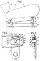
- Figure 1 is a side view of a seat of a motor vehicle having four load sensing mountings, one at each corner, in accordance with the present invention;
- Figure 2 is an enlarged side view of one of the load sensing mountings of Figure 1; and
- Figure 3 is a cross-sectional view on the line A-A of Figure 2.
- Referring to the drawings, a
seat 10 of a motor vehicle is mounted on a pair ofrails 12 in the vehicle by fourload sensing mountings 14 in accordance with the present invention. The number ofload sensing mountings 14 is dependent on the design of theseat 10. Theseat 10 comprises aseat cushion 16 and a seat back 18. Eachload sensing mounting 14 provides a connection between theseat 10 and one of therails 12 and includes aseat frame 20 on which thecushion 16 is mounted, and amounting bracket 22 which is attached to one of therails 12. - Each
load sensing mounting 14 comprises a substantiallyU-shaped bearing bracket 24 which is secured, for example by aweld 26, to theseat frame 20. Abolt 28 has ahead 30 which is secured to themounting bracket 22, and ashank 32 which extends through anaperture 34 in theseat frame 20 and between thearms 36 of thebearing bracket 24. Theaperture 34 in theseat frame 20 has an elongate shape with a predetermined clearance in a substantially vertical direction relative to theshank 32 to allow limited relative movement in the vertical direction between theseat frame 20 and thebracket 22. Thearms 36 of thebearing bracket 28 define aguideway 37 therebetween for the guidingmovement shank 32 of thebolt 28 in a substantially vertical direction. Aresilient plate 38 is secured, for example, byscrews 40 or a snap fit connection, to thefree ends 42 of thearms 36 of thebearing bracket 24 to extend across theguideway 37. Theresilient plate 38 engages theshank 32 of thebolt 28 to retain theshank 32 in theguideway 37 between thearms 36 of thebearing bracket 24. Astrain sensing element 44 is mounted on theresilient plate 38 on the opposite side of the resilient plate to theshank 32 of thebolt 28. - The
strain sensing element 44 may be any suitable element such as a foil, silicon, or thick film strain gauge. The mass of theseat 10 and the mass of an occupant sitting in the seat and/or a child seat positioned in the seat, exerts a force on theshank 32 of thebolt 28. This force creates a reaction on theresilient plate 38 which is sensed by theelement 44 which can provide an output signal which is dependent on the mass of theseat 10 and any occupant sitting in the seat. By electrically connecting theelement 44 of each load sensing mounting 14 to a suitable electronic control unit (not shown), the control unit can determine both the presence of, and the mass of, an occupant and can provide suitable signals for controlling the operation of an adaptive restraint system (not shown) associated with theseat 10 which are dependent on the determined mass. - The present invention therefore has the advantage that a highly accurate signal can be provided for controlling the operation of an adaptive restraint which is based on the size of an occupant in the seat. Also, the present invention has no influence on seat comfort or durability.
- The predetermined clearance between the
aperture 34 and theshank 32 of thebolt 28 is determined dependent on the required output from theelement 44, the thickness of theresilient plate 38, and any required overload protection for theelement 44. - As an alternative to the above described arrangement, the positioning of the
bearing bracket 24 andbolt 28 could be reversed, with the bearing bracket being secured to themounting bracket 22 and the bolt being secured to theseat frame 20. In this case, theaperture 34 would be in themounting bracket 22, and thebearing bracket 24 would be inverted (compared to Figures 1 to 3) with theresilient plate 38 andstrain sensing element 44 positioned below theshank 32 of thebolt 28. - In either of the above described arrangements, the load sensing mounting of the present invention measures any deflection of the
resilient plate 38 due to a load being placed in theseat 10, and uses the measured deflection to calculate the mass of the load. Theresilient plate 38 may be secured at both ends as shown, or secured at one end only. Theresilient plate 38 may be integrally formed with theseat frame 20 or themounting bracket 22. - The
bearing bracket 24 provides theguideway 37 for movement of theshank 32 of thebolt 28. Other suitable shapes for the bearing bracket may be used, or the bearing bracket could be integrally formed on theseat frame 20 or themounting bracket 22, to provide the required guideway for theshank 32 of thebolt 28.
Claims (6)
- A load sensing mounting (14) for mounting a vehicle seat (10) in a motor vehicle comprising a frame member (20) for the vehicle seat; a mounting bracket (22) for securing in the motor vehicle; a bearing bracket (24) on one of the mounting bracket or the frame member and having a guideway (37) extending in a substantially vertical direction; a bolt (28) secured to the other of the mounting bracket or the frame member, the bolt having a shank (32) which extends through an aperture (34) in said one of the mounting bracket or the frame member and into the guideway of the bearing bracket, the aperture having a predetermined clearance in a substantially vertical direction relative to the shank of the bolt; a resilient plate (38) secured to the bearing bracket across the guideway and engaging the shank of the bolt; and a strain sensing element (44) mounted on the resilient plate on the opposed side to the shank of the bolt.
- A load sensing mounting as claimed in Claim 1, wherein the aperture is in the seat frame; the bearing bracket is on the seat frame; and the bolt is secured to the mounting bracket.
- A load sensing mounting as claimed in Claim 1 or Claim 2, wherein the resilient plate is secured to the bearing bracket at both ends of the resilient plate.
- A load sensing mounting as claimed in any one of Claims 1 to 3, wherein the bearing bracket is substantially U-shaped having arms defining the guideway therebetween; and wherein the resilient plate is secured to the bearing bracket to close the guideway.
- A load sensing mounting as claimed in any one of Claims 1 to 4, wherein the bearing bracket is separately formed and secured to said one of the frame member or the mounting bracket.
- A load sensing mounting as claimed in any one of Claims 1 to 5, wherein the strain sensing element is a foil, silicon or thick film strain gauge.
Applications Claiming Priority (2)
| Application Number | Priority Date | Filing Date | Title |
|---|---|---|---|
| GB9809452A GB2337027B (en) | 1998-05-05 | 1998-05-05 | Load sensing mounting for a vehicle seat |
| GB9809452 | 1998-05-05 |
Publications (3)
| Publication Number | Publication Date |
|---|---|
| EP0955203A2 true EP0955203A2 (en) | 1999-11-10 |
| EP0955203A3 EP0955203A3 (en) | 2001-01-31 |
| EP0955203B1 EP0955203B1 (en) | 2005-11-02 |
Family
ID=10831389
Family Applications (1)
| Application Number | Title | Priority Date | Filing Date |
|---|---|---|---|
| EP99200958A Expired - Lifetime EP0955203B1 (en) | 1998-05-05 | 1999-03-29 | Load sensing mounting for a vehicle seat |
Country Status (3)
| Country | Link |
|---|---|
| EP (1) | EP0955203B1 (en) |
| DE (1) | DE69928042T2 (en) |
| GB (1) | GB2337027B (en) |
Cited By (3)
| Publication number | Priority date | Publication date | Assignee | Title |
|---|---|---|---|---|
| WO2002102618A1 (en) * | 2001-05-01 | 2002-12-27 | Bizerba Gmbh & Co. Kg | Vehicle seat |
| FR2834063A1 (en) * | 2001-12-21 | 2003-06-27 | Sartorius Gmbh | WEIGHT MEASURING DEVICE ACTING ON A VEHICLE SEAT AND FITTING THE SEAT THEREFOR |
| EP1498703A2 (en) * | 2003-07-14 | 2005-01-19 | Delphi Technologies, Inc. | Vehicle occupant weight estimation apparatus |
Families Citing this family (1)
| Publication number | Priority date | Publication date | Assignee | Title |
|---|---|---|---|---|
| JP4585054B2 (en) * | 1999-03-09 | 2010-11-24 | タカタ株式会社 | Seat weight measuring device |
Family Cites Families (6)
| Publication number | Priority date | Publication date | Assignee | Title |
|---|---|---|---|---|
| US3672699A (en) * | 1970-07-13 | 1972-06-27 | Eaton Corp | Automatic restraint system arming control |
| US5232243A (en) * | 1991-04-09 | 1993-08-03 | Trw Vehicle Safety Systems Inc. | Occupant sensing apparatus |
| DE19615321A1 (en) * | 1996-04-17 | 1997-10-23 | Daimler Benz Ag | Safety device for a vehicle with a removable seat, especially a passenger seat |
| JPH09301120A (en) * | 1996-05-20 | 1997-11-25 | Toyoda Gosei Co Ltd | Occupant restricting device |
| WO1998030411A1 (en) * | 1997-01-08 | 1998-07-16 | Automotive Systems Laboratory, Inc. | Automotive seat weight sensing system |
| US5739757A (en) * | 1997-01-30 | 1998-04-14 | Breed Automotive Technology, Inc. | Vehicle passenger weight sensor |
-
1998
- 1998-05-05 GB GB9809452A patent/GB2337027B/en not_active Expired - Fee Related
-
1999
- 1999-03-29 EP EP99200958A patent/EP0955203B1/en not_active Expired - Lifetime
- 1999-03-29 DE DE69928042T patent/DE69928042T2/en not_active Expired - Fee Related
Non-Patent Citations (1)
| Title |
|---|
| None |
Cited By (5)
| Publication number | Priority date | Publication date | Assignee | Title |
|---|---|---|---|---|
| WO2002102618A1 (en) * | 2001-05-01 | 2002-12-27 | Bizerba Gmbh & Co. Kg | Vehicle seat |
| US6903280B2 (en) | 2001-05-01 | 2005-06-07 | Bizerba Gbmh & Co. Kg | Vehicle seat |
| FR2834063A1 (en) * | 2001-12-21 | 2003-06-27 | Sartorius Gmbh | WEIGHT MEASURING DEVICE ACTING ON A VEHICLE SEAT AND FITTING THE SEAT THEREFOR |
| EP1498703A2 (en) * | 2003-07-14 | 2005-01-19 | Delphi Technologies, Inc. | Vehicle occupant weight estimation apparatus |
| EP1498703A3 (en) * | 2003-07-14 | 2006-10-25 | Delphi Technologies, Inc. | Vehicle occupant weight estimation apparatus |
Also Published As
| Publication number | Publication date |
|---|---|
| DE69928042D1 (en) | 2005-12-08 |
| EP0955203A3 (en) | 2001-01-31 |
| GB9809452D0 (en) | 1998-07-01 |
| DE69928042T2 (en) | 2006-04-20 |
| GB2337027A (en) | 1999-11-10 |
| GB2337027B (en) | 2001-11-21 |
| EP0955203B1 (en) | 2005-11-02 |
Similar Documents
| Publication | Publication Date | Title |
|---|---|---|
| EP1731378B1 (en) | Capacitive occupant sensor for a vehicle seat | |
| US7047825B2 (en) | Sensor assembly for measuring weight applied to a vehicle seat | |
| US7143658B2 (en) | Deflection plate weight sensor for vehicle seat | |
| EP1172262B1 (en) | Seat load sensing apparatus | |
| EP0962362A3 (en) | A seat weight measuring apparatus | |
| US6797892B2 (en) | Force transducer for a motor vehicle seat that includes a housing surrounding an extension member of the force transducer | |
| US6288649B1 (en) | Weight sensing apparatus | |
| US7513475B2 (en) | Weight transfer link | |
| US6670560B2 (en) | Sensor integrated bracket for weight classification | |
| EP1503189B1 (en) | Frame-based occupant weight estimation load cell with ball-actuated force sensor | |
| US6824165B2 (en) | Weight sensor assembly for determining seat occupant weight | |
| US6559392B1 (en) | Weight-sensing support assembly for automotive seat cushion frame | |
| KR20010075147A (en) | Motor vehicle seat having an integrated occupancy detection system | |
| EP1330379B1 (en) | Seatbelt force sensor with overload protection | |
| EP0955203B1 (en) | Load sensing mounting for a vehicle seat | |
| US20050099041A1 (en) | Motor vehicle seat with occupant weight detection system | |
| US20030229431A1 (en) | Electrical circuit module with magnetic detection of loose or detached state | |
| US7021162B2 (en) | Belt force measuring device | |
| JP2001158269A (en) | Seated occupant detector | |
| US20040154843A1 (en) | Device for receiving a force acting upon a vehicles seat | |
| US20060125272A1 (en) | Seat rail assembly capable of sensing weight | |
| JP2005254926A (en) | Load sensor for vehicular seat, and vehicular seat |
Legal Events
| Date | Code | Title | Description |
|---|---|---|---|
| PUAI | Public reference made under article 153(3) epc to a published international application that has entered the european phase |
Free format text: ORIGINAL CODE: 0009012 |
|
| AK | Designated contracting states |
Kind code of ref document: A2 Designated state(s): DE FR GB IT SE |
|
| AX | Request for extension of the european patent |
Free format text: AL;LT;LV;MK;RO;SI |
|
| PUAL | Search report despatched |
Free format text: ORIGINAL CODE: 0009013 |
|
| AK | Designated contracting states |
Kind code of ref document: A3 Designated state(s): AT BE CH CY DE DK ES FI FR GB GR IE IT LI LU MC NL PT SE |
|
| AX | Request for extension of the european patent |
Free format text: AL;LT;LV;MK;RO;SI |
|
| 17P | Request for examination filed |
Effective date: 20010731 |
|
| AKX | Designation fees paid |
Free format text: DE FR GB IT SE |
|
| GRAP | Despatch of communication of intention to grant a patent |
Free format text: ORIGINAL CODE: EPIDOSNIGR1 |
|
| RBV | Designated contracting states (corrected) |
Designated state(s): DE FR IT SE |
|
| GRAS | Grant fee paid |
Free format text: ORIGINAL CODE: EPIDOSNIGR3 |
|
| GRAA | (expected) grant |
Free format text: ORIGINAL CODE: 0009210 |
|
| AK | Designated contracting states |
Kind code of ref document: B1 Designated state(s): DE FR IT SE |
|
| REG | Reference to a national code |
Ref country code: SE Ref legal event code: TRGR |
|
| REF | Corresponds to: |
Ref document number: 69928042 Country of ref document: DE Date of ref document: 20051208 Kind code of ref document: P |
|
| ET | Fr: translation filed | ||
| PLBE | No opposition filed within time limit |
Free format text: ORIGINAL CODE: 0009261 |
|
| STAA | Information on the status of an ep patent application or granted ep patent |
Free format text: STATUS: NO OPPOSITION FILED WITHIN TIME LIMIT |
|
| 26N | No opposition filed |
Effective date: 20060803 |
|
| PGFP | Annual fee paid to national office [announced via postgrant information from national office to epo] |
Ref country code: SE Payment date: 20080306 Year of fee payment: 10 Ref country code: IT Payment date: 20080327 Year of fee payment: 10 |
|
| PGFP | Annual fee paid to national office [announced via postgrant information from national office to epo] |
Ref country code: FR Payment date: 20080311 Year of fee payment: 10 Ref country code: DE Payment date: 20080407 Year of fee payment: 10 |
|
| EUG | Se: european patent has lapsed | ||
| REG | Reference to a national code |
Ref country code: FR Ref legal event code: ST Effective date: 20091130 |
|
| PG25 | Lapsed in a contracting state [announced via postgrant information from national office to epo] |
Ref country code: DE Free format text: LAPSE BECAUSE OF NON-PAYMENT OF DUE FEES Effective date: 20091001 |
|
| PG25 | Lapsed in a contracting state [announced via postgrant information from national office to epo] |
Ref country code: FR Free format text: LAPSE BECAUSE OF NON-PAYMENT OF DUE FEES Effective date: 20091123 |
|
| PG25 | Lapsed in a contracting state [announced via postgrant information from national office to epo] |
Ref country code: IT Free format text: LAPSE BECAUSE OF NON-PAYMENT OF DUE FEES Effective date: 20090329 |
|
| PG25 | Lapsed in a contracting state [announced via postgrant information from national office to epo] |
Ref country code: SE Free format text: LAPSE BECAUSE OF NON-PAYMENT OF DUE FEES Effective date: 20090330 |