EP0955775A2 - Method for displaying devices connected to a network - Google Patents
Method for displaying devices connected to a network Download PDFInfo
- Publication number
- EP0955775A2 EP0955775A2 EP99303481A EP99303481A EP0955775A2 EP 0955775 A2 EP0955775 A2 EP 0955775A2 EP 99303481 A EP99303481 A EP 99303481A EP 99303481 A EP99303481 A EP 99303481A EP 0955775 A2 EP0955775 A2 EP 0955775A2
- Authority
- EP
- European Patent Office
- Prior art keywords
- operates
- client
- devices
- operate
- servers
- Prior art date
- Legal status (The legal status is an assumption and is not a legal conclusion. Google has not performed a legal analysis and makes no representation as to the accuracy of the status listed.)
- Granted
Links
Images


Classifications
-
- H—ELECTRICITY
- H04—ELECTRIC COMMUNICATION TECHNIQUE
- H04N—PICTORIAL COMMUNICATION, e.g. TELEVISION
- H04N21/00—Selective content distribution, e.g. interactive television or video on demand [VOD]
- H04N21/40—Client devices specifically adapted for the reception of or interaction with content, e.g. set-top-box [STB]; Operations thereof
- H04N21/43—Processing of content or additional data, e.g. demultiplexing additional data from a digital video stream; Elementary client operations, e.g. monitoring of home network or synchronising decoder's clock; Client middleware
- H04N21/436—Interfacing a local distribution network, e.g. communicating with another STB or one or more peripheral devices inside the home
- H04N21/43615—Interfacing a Home Network, e.g. for connecting the client to a plurality of peripherals
-
- H—ELECTRICITY
- H04—ELECTRIC COMMUNICATION TECHNIQUE
- H04L—TRANSMISSION OF DIGITAL INFORMATION, e.g. TELEGRAPHIC COMMUNICATION
- H04L12/00—Data switching networks
- H04L12/02—Details
- H04L12/22—Arrangements for preventing the taking of data from a data transmission channel without authorisation
-
- H—ELECTRICITY
- H04—ELECTRIC COMMUNICATION TECHNIQUE
- H04L—TRANSMISSION OF DIGITAL INFORMATION, e.g. TELEGRAPHIC COMMUNICATION
- H04L12/00—Data switching networks
- H04L12/28—Data switching networks characterised by path configuration, e.g. LAN [Local Area Networks] or WAN [Wide Area Networks]
- H04L12/2803—Home automation networks
- H04L12/2805—Home Audio Video Interoperability [HAVI] networks
-
- H—ELECTRICITY
- H04—ELECTRIC COMMUNICATION TECHNIQUE
- H04L—TRANSMISSION OF DIGITAL INFORMATION, e.g. TELEGRAPHIC COMMUNICATION
- H04L12/00—Data switching networks
- H04L12/28—Data switching networks characterised by path configuration, e.g. LAN [Local Area Networks] or WAN [Wide Area Networks]
- H04L12/2803—Home automation networks
- H04L12/2823—Reporting information sensed by appliance or service execution status of appliance services in a home automation network
- H04L12/2825—Reporting to a device located outside the home and the home network
-
- H—ELECTRICITY
- H04—ELECTRIC COMMUNICATION TECHNIQUE
- H04L—TRANSMISSION OF DIGITAL INFORMATION, e.g. TELEGRAPHIC COMMUNICATION
- H04L12/00—Data switching networks
- H04L12/28—Data switching networks characterised by path configuration, e.g. LAN [Local Area Networks] or WAN [Wide Area Networks]
- H04L12/40—Bus networks
- H04L12/40052—High-speed IEEE 1394 serial bus
- H04L12/40117—Interconnection of audio or video/imaging devices
-
- H—ELECTRICITY
- H04—ELECTRIC COMMUNICATION TECHNIQUE
- H04N—PICTORIAL COMMUNICATION, e.g. TELEVISION
- H04N21/00—Selective content distribution, e.g. interactive television or video on demand [VOD]
- H04N21/20—Servers specifically adapted for the distribution of content, e.g. VOD servers; Operations thereof
- H04N21/23—Processing of content or additional data; Elementary server operations; Server middleware
- H04N21/236—Assembling of a multiplex stream, e.g. transport stream, by combining a video stream with other content or additional data, e.g. inserting a URL [Uniform Resource Locator] into a video stream, multiplexing software data into a video stream; Remultiplexing of multiplex streams; Insertion of stuffing bits into the multiplex stream, e.g. to obtain a constant bit-rate; Assembling of a packetised elementary stream
- H04N21/2368—Multiplexing of audio and video streams
-
- H—ELECTRICITY
- H04—ELECTRIC COMMUNICATION TECHNIQUE
- H04N—PICTORIAL COMMUNICATION, e.g. TELEVISION
- H04N21/00—Selective content distribution, e.g. interactive television or video on demand [VOD]
- H04N21/40—Client devices specifically adapted for the reception of or interaction with content, e.g. set-top-box [STB]; Operations thereof
- H04N21/41—Structure of client; Structure of client peripherals
- H04N21/414—Specialised client platforms, e.g. receiver in car or embedded in a mobile appliance
- H04N21/4147—PVR [Personal Video Recorder]
-
- H—ELECTRICITY
- H04—ELECTRIC COMMUNICATION TECHNIQUE
- H04N—PICTORIAL COMMUNICATION, e.g. TELEVISION
- H04N21/00—Selective content distribution, e.g. interactive television or video on demand [VOD]
- H04N21/40—Client devices specifically adapted for the reception of or interaction with content, e.g. set-top-box [STB]; Operations thereof
- H04N21/43—Processing of content or additional data, e.g. demultiplexing additional data from a digital video stream; Elementary client operations, e.g. monitoring of home network or synchronising decoder's clock; Client middleware
- H04N21/434—Disassembling of a multiplex stream, e.g. demultiplexing audio and video streams, extraction of additional data from a video stream; Remultiplexing of multiplex streams; Extraction or processing of SI; Disassembling of packetised elementary stream
- H04N21/4341—Demultiplexing of audio and video streams
-
- H—ELECTRICITY
- H04—ELECTRIC COMMUNICATION TECHNIQUE
- H04N—PICTORIAL COMMUNICATION, e.g. TELEVISION
- H04N21/00—Selective content distribution, e.g. interactive television or video on demand [VOD]
- H04N21/40—Client devices specifically adapted for the reception of or interaction with content, e.g. set-top-box [STB]; Operations thereof
- H04N21/43—Processing of content or additional data, e.g. demultiplexing additional data from a digital video stream; Elementary client operations, e.g. monitoring of home network or synchronising decoder's clock; Client middleware
- H04N21/436—Interfacing a local distribution network, e.g. communicating with another STB or one or more peripheral devices inside the home
- H04N21/4363—Adapting the video or multiplex stream to a specific local network, e.g. a IEEE 1394 or Bluetooth® network
- H04N21/43632—Adapting the video or multiplex stream to a specific local network, e.g. a IEEE 1394 or Bluetooth® network involving a wired protocol, e.g. IEEE 1394
Definitions
- the present invention relates to a network, and more particularly, to a method for displaying devices in a network by which a user can see the operations of devices connected to the network through a device among the devices.
- DTV digital TV
- DVCR digital VCR
- a digital set top box a digital set top box
- IEC 61883 The network in which the digital devices are connected to each other, thus performing communication is highlighted (please refer documents such as IEEE 1394-1995 High Performance Serial Bus, IEC 61883).
- Figure 1 shows a protocol stack of a network device (1394 device).
- a general protocol stack which the respective devices adopting a network communication function is comprised of a physical layer 100 which is the lowest layer 100, a link layer 110, a transaction layer 120, and a serial bus management layer 130 which is the upper most layer.
- the physical layer 100 receives a bit column from the link layer 110 during transmission, obtains the right to use a serial bus, encodes the bit column, converts the bit column into an electrical signal, and transfers the signal to an external bus. Reverse processes are performed during reception.
- the link layer 110 deals with data in units of a packet and has functions of constructing and dismantling a packet, detecting errors, and managing a bus cycle.
- the physical layer 100 and the link layer 110 are comprised of a chipset.
- the transaction layer 120 provides a transaction such as reading/writing/locking of data and performs asynchronous communication with different devices (or nodes) put on the network bus using the service provided by the lowest layer.
- a serial bus management layer 130 holds various material structures such as a configuration ROM and a control and status register (CSR) and manages a connection structure of an entire system connected to a power supply and a bus (topology)/ speed map.
- CSR control and status register
- the transaction layer 120 and the serial bus management layer 130 are formed of software and is realized by being built-in the microcomputer of the respective devices.
- Figure 2 shows a block diagram of a digital device having the network communication function.
- the digital device is comprised of a device dependent hardware 200, a microcomputer 210, a physical layer execution block 220, and a link layer execution block 230.
- the device dependent hardware 200 executes a characteristic function of a concerned device.
- the microcomputer 210 for supporting the network communication executes the operation including the transaction layer and the serial bus management layer, described in Figure 1.
- the physical layer execution block 220 is hardware for realizing the function of the physical layer 100 of Figure 1.
- the link layer execution block 230 is hardware for realizing the CIP header inserting/removing functions of IEC 61883.
- a method for displaying the operations of devices on a display screen of a device which operates as a client in a network when various digital devices connected to the network operate as the client or the servers, having the same protocol layer as an Internet protocol stack on the upper network communication layer comprising the steps of (a) the device which operates as the client requesting the remaining devices which operate as the servers to send characteristic information that they have, (b) displaying the representative information of the server device on the device which operates as the client when the representative information in which information representing a concerned device is implied is transmitted from the devices which operate as the servers to the device which operates as the client, (c) the device which operates as the client requesting the remaining devices which operate as the servers to send the multimedia information during the operations executed by the server devices, and (d) the device which operates as the client receiving each multimedia information from the devices which operate as the servers and displaying the image of the multimedia information where the representative information of the concerned device is positioned.
- the representative information is preferably icon image information by which it is possible to classify the server devices.
- the flickers of the icons preferably vary according to whether the devices operate or not in the step (b).
- the representative information of the device which operates as the client is further displayed in the step (b).
- the step (d) may comprise the steps of: the device which operates as the client receiving image data in parallel from the devices which operate as the servers; the device which operates as the client decoding the received image data in parallel; and the device which operates as the client displaying the decoded image data in the position of the representative image of a concerned device on the screen thereof.
- the step (d) may comprise the steps of: the device which operates as the client sequentially receiving the image data of the devices which operate as the servers in every predetermined period and decoding the image data; and the device which operates as the client displaying the decoded image data in the position of the representative image of a concerned device on the screen thereof.
- the step (d) may comprise the steps of: the device which operates as the client sequentially receiving and decoding each I frame of the image data of the devices which operate as the servers; and displaying the decoded image data in the position of the representative information of a concerned device on the screen of the device which operates as the client.
- the step (d) may comprise the steps of: the device which operates as the client receiving the image data of the devices which operate as the servers; the device which operates as the client decoding the image data received from the devices which operate as the servers by an AVI format data in order to express the image data as a moving image; and displaying the decoded data in the position of the representative information of the concerned device on the screen of the device which operates as the client.
- the step (d) may comprise the steps of: the device which operates as the client receiving and decoding only one I frame of each device among the image data of the devices which operate as the servers; and displaying the decoded image data in the position of the representative information of a concerned device on the screen of the device which operates as the client.
- the network is preferably an IEEE 1394 network.
- a method for displaying the operations of devices on a display screen of a device which operates as a client in a network when various digital devices connected to the network operate as the client or the servers, having the same protocol layer as an Internet protocol stack on the upper network communication layer comprising the steps of (a) the device which operates as the client requesting the remaining devices which operate as the servers to send characteristic information that they have, (b) displaying the representative information of the server device on the device which operates as the client when the representative information in which information representing a concerned device is implied is transmitted from the devices which operate as the servers to the device which operates as the client, (c) a user selecting the representative information of a predetermined device with the representative information of each device which operates as a server is displayed on the screen of the device which operates as the client, (d) the device which operates as the client requesting the selected device to send operation data, (e) the device which operates as the client receiving multimedia data from the selected device which operates as the server and decoding the received signal according to
- the representative information may be icon image information for classifying the server device.
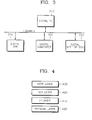
- FIG 3 is an example of the structure of a network for describing the present invention.
- a digital TV 300, a digital VCR 310, a digital camcorder 320, and a digital set top box 330 are connected to a network bus.
- the respective digital devices 300 through 330 execute data communication according to a client/server method used in a general intranet/Internet, including a protocol layer as shown in Figure 4.
- the digital TV 300 by which a user can see predetermined image and character data on a screen operates as a client and includes a web browser.
- the digital devices 310 through 330 play the same role as that of a web server on the Internet.
- the devices connected to the network bus give and take hypertext documented data as in the Internet.
- the hypertext document to be transferred by the respective devices include information on the functions and the operations of the respective devices.
- the digital TV 300 which is the client accesses the respective web sites from the web server devices 310 through 330 using the web browser and controls concerned devices. Namely, a user accesses the web sites of the remaining devices connected to the network using the web browser of the digital TV 300 and controls the characteristic operations of the concerned devices in the respective web sites.
- the characteristic operations of the respective devices and predetermined device information are included in the web sites provided by the digital devices 300 through 330 connected to the network.
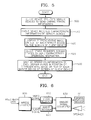
- Figure 4 shows the network protocol layer of Figure 3, which is comprised of a network physical layer 400, an IP layer 410, a transmission control protocol (TCP) layer 420, and hypertext transmission protocol (HTTP) layer 430.
- the network physical layer 400 is a layer for transmitting and receiving data through a network bus.
- IP layer 410 a protocol for connecting independently managed communication networks to each other is adopted in order to use the communication networks together.
- TCP layer 420 a communication net protocol of a system connected through the Internet is adopted.
- HTTP layer 430 a communication protocol used for exchanging the hypertext document in the Internet is adopted.
- FIG. 5 is a flowchart of a method for displaying devices in the network of the present invention, which will be described, taking the system of Figure 3 as an example.
- the digital TV 300 which is the client device requests the digital VCR 310, the digital camcorder 320, and the digital set top box 330, which are server devices, to send predetermined characteristic information that they have (step 500).
- the above-mentioned server devices accept this request and sends the characteristic information which they have such as kinds of products and manufacture, to the digital TV 300 which is the client (step 510).
- the pattern of the characteristic information is shown as a picture in which information for classifying products is implied, namely, is representative information (icon information or text information) which represents a concerned device.
- the digital TV 300 receives characteristic information from the server devices and displays the representative information received from the respective server devices and the representative information thereof at predetermined positions of a screen (step 520).
- the digital TV 300 requests the server devices 310 through 330 to transfer information during the execution of the respective characteristic operations (such as reproduced screen information during a digital VTR 310 reproducing operation) (step 530).
- the operation information received from the server devices is multimedia information such as a video signal or an audio signal.
- the digital TV 300 displays the multimedia information where the representative information of the concerned device is displayed (step 540).
- FIG. 6 is a block diagram showing processes in which the information received from the server devices is decoded by the digital TV 300 in the explanation of Figure 5.
- data which the digital devices deal with is generally MPEG2 data
- processes of decoding the data are executed by an MPEG2 decoder 600.
- the MPEG2 decoder 600 decodes data and separately extracts the video signal and the audio signal.
- the video signal and the audio signal extracted by the MPEG2 decoder 600 are respectively input to a video decoder 610 and an audio decoder 620, are decoded, and are converted into analog signals through an analog signal converter 630.
- the video analog signal is output through the screen of the digital TV 300.
- the audio analog signal is output through a speaker loaded into the digital TV 300. Accordingly, a user can see the operations of different devices which are connected to each other through the screen of the digital TV 300 or the speaker.
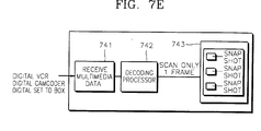
- FIGs 7A through 7E are block diagrams of embodiments of various processes in which the operation data of the server devices are input to the digital TV 300 and are displayed in Figure 5.
- the multimedia data from the server devices are received by the digital TV 300 in parallel (step 701).
- the digital TV 300 decodes the received parallel data through decoding processors as shown in Figure 6 (step 702).
- the video signal is displayed where the concerned device representative information positioned on the screen of the digital TV 300 (step 703).
- the multimedia data of the server devices are sequentially input to the digital TV 300 in every predetermined period (step 711).
- the digital TV 300 decodes the data received through one decoding processor as shown in Figure 6 (step 712) and displays the decoded data where the concerned device representative information is positioned on the screen of the digital TV 300 (step 713).
- the multimedia data of the server devices are sequentially input to the digital TV 300 (step 721).
- the digital TV 300 decodes the received data through one decoding processor (step 722). I frames of the respective devices are sensed and sequentially decoded. For example, I frames among the video signals of the digital VCR 310 is read and decoded. Continuously, I frames among the video signals of the digital camcorder 320 are read and decoded. Also, I frames among the video signals of the digital set top box 330 is read and decoded.
- the decoded video signal is displayed in the position of the representative image of the concerned device which is displayed on the screen of the digital TV 300 (step 723). Only I frame of the operation screen of each device displayed on the screen of the digital TV 300 is displayed. Accordingly, an image of a snap shot pattern changes in every predetermined period.
- the multimedia data of the server devices are selectively or periodically received by the digital TV 300 (step 731).
- the digital TV 300 decodes the received data by an audio video interleaved (AVI) format used for expressing the received data as a moving image (step 732).
- the data decoded by the AVI format is scanned on the screen of the digital TV 300 and is displayed in the position of the representative information of the concerned device.
- the picture displayed as mentioned above is shown as the moving image to the user.
- a moving image display is commonly used in a general web browser.
- the digital TV 300 receives the multimedia data from the server devices (step 741), decodes the received signal through the decoding processor as shown in Figure 6 (step 742), and displays only one I frame from each decoded device signal in the position of the representative information of the concerned device on the screen of the digital TV 300 (step 743).
- the picture displayed as mentioned above is shown to the user as a still picture of the snap shot pattern.
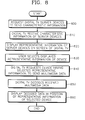
- Figure 8 is another embodiment of a method for displaying devices in the network of the present invention, which will be described taking Figure 3 as an example. Descriptions of steps 800 through 820 will be omitted since they are identical to those of the steps 500 to 520 of Figure 5.
- the representative information of the respective devices are displayed on the screen of the digital TV 300 (the step 820)
- the representative information of a predetermined device is selected by the user (step 830).
- the digital TV 300 requests the operation data to the device having selected representative information (step 840).
- the operation data refer to the multimedia information such as a reproduced image and a sound signal when the digital VCR 310 executes the reproducing operation when the digital VCR 310 is selected.
- the digital TV 300 receives the multimedia information from the selected device during the concerned operation and decodes the multimedia information according to a predetermined device (step 850).
- the digital TV 300 displays the decoded signal where the representative information of the concerned server device is positioned on the screen thereof (step 860). In such a process, only when the user selects one device among the server devices displayed on the screen of the digital TV 300, the operation data are received from the selected device and displayed.
- the network can perform communication by a client/server method like the IEEE 1394 network.
- the above-mentioned embodiment of the present invention can be embodied in a program which can be executed in a computer.
- the embodiment can be realized in a generally used digital computer for operating the program from a medium used in the computer.
- the medium includes a storage medium such as a magnetic storage medium (FOD and HOD), optical storage medium (CD-ROM and DVD) or a carrier wave (transferred through the Internet).
- the recording medium stores a program code which can execute a first step in which the device which operates as the client requests the remaining devices which operate as servers to send characteristic information that they have, a second step in which the representative information of the server devices is displayed on the screen of the device which operates as the client when the representative information in which the information representing a concerned device is implied is transmitted from the devices which operate as servers to the device which operates as the client, a third step in which the device which operates as the client requests the devices which operates as the servers to send the multimedia information during the operations of the server devices, and a fourth step in which the device which operates as the client receives each multimedia information from the devices which operate as the servers and displays the image of the multimedia information where the representative information of the concerned device is positioned, in the network system having the protocol stack of Figure 4.
- the program is positioned in an upper layer as it prevents more errors of the video data.
- the upper layer and the lower layer have backward compatibility in which the upper layer includes the lower layer.
- the program is coded so that more errors are prevented with respect to data which considerably affects picture quality.
- a functional program, a code, and a code segment for realizing the present invention can be easily realized by programmers knowledgeable in the art.
- the user can see the operations of the devices on the network on the screen of one device among the devices and can easily control a desired device on the screen.
Abstract
Description
- The present invention relates to a network, and more particularly, to a method for displaying devices in a network by which a user can see the operations of devices connected to the network through a device among the devices.
- Recently, various digital devices such as a digital TV (DTV), a digital VCR (DVCR), and a digital set top box have appeared. The network in which the digital devices are connected to each other, thus performing communication is highlighted (please refer documents such as IEEE 1394-1995 High Performance Serial Bus, IEC 61883).
- Figure 1 shows a protocol stack of a network device (1394 device). A general protocol stack which the respective devices adopting a network communication function is comprised of a
physical layer 100 which is thelowest layer 100, alink layer 110, atransaction layer 120, and a serialbus management layer 130 which is the upper most layer. Thephysical layer 100 receives a bit column from thelink layer 110 during transmission, obtains the right to use a serial bus, encodes the bit column, converts the bit column into an electrical signal, and transfers the signal to an external bus. Reverse processes are performed during reception. Thelink layer 110 deals with data in units of a packet and has functions of constructing and dismantling a packet, detecting errors, and managing a bus cycle. In general, thephysical layer 100 and thelink layer 110 are comprised of a chipset. Thetransaction layer 120 provides a transaction such as reading/writing/locking of data and performs asynchronous communication with different devices (or nodes) put on the network bus using the service provided by the lowest layer. A serialbus management layer 130 holds various material structures such as a configuration ROM and a control and status register (CSR) and manages a connection structure of an entire system connected to a power supply and a bus (topology)/ speed map. Thetransaction layer 120 and the serialbus management layer 130 are formed of software and is realized by being built-in the microcomputer of the respective devices. - Figure 2 shows a block diagram of a digital device having the network communication function. The digital device is comprised of a device
dependent hardware 200, amicrocomputer 210, a physicallayer execution block 220, and a linklayer execution block 230. The devicedependent hardware 200 executes a characteristic function of a concerned device. Themicrocomputer 210 for supporting the network communication executes the operation including the transaction layer and the serial bus management layer, described in Figure 1. The physicallayer execution block 220 is hardware for realizing the function of thephysical layer 100 of Figure 1. The linklayer execution block 230 is hardware for realizing the CIP header inserting/removing functions of IEC 61883. - In a conventional technology, various digital devices are connected to each other on the network as mentioned above and transmits and receives data. However, a user cannot see the operations of all the devices at one sight.
- With a view to solve or reduce the above problem, it is an aim of embodiments of the present invention to provide a method for displaying devices in a network by which a user can see the operations of the devices on the network on a screen of one device and control them.
- According to a first aspect of the invention, there is provided a method for displaying the operations of devices on a display screen of a device which operates as a client in a network when various digital devices connected to the network operate as the client or the servers, having the same protocol layer as an Internet protocol stack on the upper network communication layer, comprising the steps of (a) the device which operates as the client requesting the remaining devices which operate as the servers to send characteristic information that they have, (b) displaying the representative information of the server device on the device which operates as the client when the representative information in which information representing a concerned device is implied is transmitted from the devices which operate as the servers to the device which operates as the client, (c) the device which operates as the client requesting the remaining devices which operate as the servers to send the multimedia information during the operations executed by the server devices, and (d) the device which operates as the client receiving each multimedia information from the devices which operate as the servers and displaying the image of the multimedia information where the representative information of the concerned device is positioned.
- The representative information is preferably icon image information by which it is possible to classify the server devices.
- The colour of the icons preferably vary according to whether the devices operate or not in the step (b).
- The flickers of the icons preferably vary according to whether the devices operate or not in the step (b).
- Preferably, the representative information of the device which operates as the client is further displayed in the step (b).
- The step (d) may comprise the steps of: the device which operates as the client receiving image data in parallel from the devices which operate as the servers; the device which operates as the client decoding the received image data in parallel; and the device which operates as the client displaying the decoded image data in the position of the representative image of a concerned device on the screen thereof.
- The step (d) may comprise the steps of: the device which operates as the client sequentially receiving the image data of the devices which operate as the servers in every predetermined period and decoding the image data; and the device which operates as the client displaying the decoded image data in the position of the representative image of a concerned device on the screen thereof.
- The step (d) may comprise the steps of: the device which operates as the client sequentially receiving and decoding each I frame of the image data of the devices which operate as the servers; and displaying the decoded image data in the position of the representative information of a concerned device on the screen of the device which operates as the client.
- The step (d) may comprise the steps of: the device which operates as the client receiving the image data of the devices which operate as the servers; the device which operates as the client decoding the image data received from the devices which operate as the servers by an AVI format data in order to express the image data as a moving image; and displaying the decoded data in the position of the representative information of the concerned device on the screen of the device which operates as the client.
- The step (d) may comprise the steps of: the device which operates as the client receiving and decoding only one I frame of each device among the image data of the devices which operate as the servers; and displaying the decoded image data in the position of the representative information of a concerned device on the screen of the device which operates as the client.
- The network is preferably an IEEE 1394 network.
- According to a second aspect of the invention, there is provided a method for displaying the operations of devices on a display screen of a device which operates as a client in a network when various digital devices connected to the network operate as the client or the servers, having the same protocol layer as an Internet protocol stack on the upper network communication layer, comprising the steps of (a) the device which operates as the client requesting the remaining devices which operate as the servers to send characteristic information that they have, (b) displaying the representative information of the server device on the device which operates as the client when the representative information in which information representing a concerned device is implied is transmitted from the devices which operate as the servers to the device which operates as the client, (c) a user selecting the representative information of a predetermined device with the representative information of each device which operates as a server is displayed on the screen of the device which operates as the client, (d) the device which operates as the client requesting the selected device to send operation data, (e) the device which operates as the client receiving multimedia data from the selected device which operates as the server and decoding the received signal according to a predetermined method, and (f) displaying the decoded signal in the position of the representative information of a concerned device on the screen of the device which operates as the client.
- The representative information may be icon image information for classifying the server device.
- For a better understanding of the invention, and to show how embodiments of the same may be carried into effect, reference will now be made, by way of example, to the accompanying diagrammatic drawings, in which:
- Figure 1 shows a protocol stack of a network device (1394 device);
- Figure 2 shows a block diagram of a digital device having a network communication function;
- Figure 3 is an example of the structure of the network for describing embodiments of the present invention;
- Figure 4 shows the network protocol stack of Figure 3;
- Figure 5 is a flowchart of a method for displaying devices in the network according to embodiments of the present invention;
- Figure 6 is a block flowchart showing processes in which information received from server devices is decoded in a digital TV in the description of Figure 5;
- Figures 7A through 7E are block diagrams describing various processes in which operation data of the server devices are input to the digital TV and are displayed in Figure 5; and
- Figure 8 is another embodiment of the method for displaying devices in the network of the present invention.
- Figure 3 is an example of the structure of a network for describing the present invention. A
digital TV 300, adigital VCR 310, adigital camcorder 320, and a digitalset top box 330 are connected to a network bus. The respectivedigital devices 300 through 330 execute data communication according to a client/server method used in a general intranet/Internet, including a protocol layer as shown in Figure 4. Here, thedigital TV 300 by which a user can see predetermined image and character data on a screen operates as a client and includes a web browser. Thedigital devices 310 through 330 play the same role as that of a web server on the Internet. The devices connected to the network bus give and take hypertext documented data as in the Internet. The hypertext document to be transferred by the respective devices include information on the functions and the operations of the respective devices. Thedigital TV 300 which is the client accesses the respective web sites from theweb server devices 310 through 330 using the web browser and controls concerned devices. Namely, a user accesses the web sites of the remaining devices connected to the network using the web browser of thedigital TV 300 and controls the characteristic operations of the concerned devices in the respective web sites. The characteristic operations of the respective devices and predetermined device information are included in the web sites provided by thedigital devices 300 through 330 connected to the network. - Figure 4 shows the network protocol layer of Figure 3, which is comprised of a network
physical layer 400, anIP layer 410, a transmission control protocol (TCP)layer 420, and hypertext transmission protocol (HTTP)layer 430. The networkphysical layer 400 is a layer for transmitting and receiving data through a network bus. In theIP layer 410, a protocol for connecting independently managed communication networks to each other is adopted in order to use the communication networks together. In the TCPlayer 420, a communication net protocol of a system connected through the Internet is adopted. In theHTTP layer 430, a communication protocol used for exchanging the hypertext document in the Internet is adopted. - Figure 5 is a flowchart of a method for displaying devices in the network of the present invention, which will be described, taking the system of Figure 3 as an example. First, the
digital TV 300 which is the client device requests thedigital VCR 310, thedigital camcorder 320, and the digitalset top box 330, which are server devices, to send predetermined characteristic information that they have (step 500). The above-mentioned server devices accept this request and sends the characteristic information which they have such as kinds of products and manufacture, to thedigital TV 300 which is the client (step 510). The pattern of the characteristic information is shown as a picture in which information for classifying products is implied, namely, is representative information (icon information or text information) which represents a concerned device. Thedigital TV 300 receives characteristic information from the server devices and displays the representative information received from the respective server devices and the representative information thereof at predetermined positions of a screen (step 520). Thedigital TV 300 requests theserver devices 310 through 330 to transfer information during the execution of the respective characteristic operations (such as reproduced screen information during adigital VTR 310 reproducing operation) (step 530). The operation information received from the server devices is multimedia information such as a video signal or an audio signal. Thedigital TV 300 displays the multimedia information where the representative information of the concerned device is displayed (step 540). - Figure 6 is a block diagram showing processes in which the information received from the server devices is decoded by the
digital TV 300 in the explanation of Figure 5. Since data which the digital devices deal with is generally MPEG2 data, processes of decoding the data are executed by anMPEG2 decoder 600. When the multimedia data are input from the server devices, theMPEG2 decoder 600 decodes data and separately extracts the video signal and the audio signal. The video signal and the audio signal extracted by theMPEG2 decoder 600 are respectively input to avideo decoder 610 and anaudio decoder 620, are decoded, and are converted into analog signals through ananalog signal converter 630. The video analog signal is output through the screen of thedigital TV 300. The audio analog signal is output through a speaker loaded into thedigital TV 300. Accordingly, a user can see the operations of different devices which are connected to each other through the screen of thedigital TV 300 or the speaker. - Figures 7A through 7E are block diagrams of embodiments of various processes in which the operation data of the server devices are input to the
digital TV 300 and are displayed in Figure 5. In the embodiment of Figure 7A, the multimedia data from the server devices are received by thedigital TV 300 in parallel (step 701). Thedigital TV 300 decodes the received parallel data through decoding processors as shown in Figure 6 (step 702). The video signal is displayed where the concerned device representative information positioned on the screen of the digital TV 300 (step 703). In the embodiment of Figure 7B, the multimedia data of the server devices are sequentially input to thedigital TV 300 in every predetermined period (step 711). Thedigital TV 300 decodes the data received through one decoding processor as shown in Figure 6 (step 712) and displays the decoded data where the concerned device representative information is positioned on the screen of the digital TV 300 (step 713). In the embodiment of Figure 7C, the multimedia data of the server devices are sequentially input to the digital TV 300 (step 721). Thedigital TV 300 decodes the received data through one decoding processor (step 722). I frames of the respective devices are sensed and sequentially decoded. For example, I frames among the video signals of thedigital VCR 310 is read and decoded. Continuously, I frames among the video signals of thedigital camcorder 320 are read and decoded. Also, I frames among the video signals of the digitalset top box 330 is read and decoded. The decoded video signal is displayed in the position of the representative image of the concerned device which is displayed on the screen of the digital TV 300 (step 723). Only I frame of the operation screen of each device displayed on the screen of thedigital TV 300 is displayed. Accordingly, an image of a snap shot pattern changes in every predetermined period. In the embodiment of Figure 7D, the multimedia data of the server devices are selectively or periodically received by the digital TV 300 (step 731). Thedigital TV 300 decodes the received data by an audio video interleaved (AVI) format used for expressing the received data as a moving image (step 732). The data decoded by the AVI format is scanned on the screen of thedigital TV 300 and is displayed in the position of the representative information of the concerned device. The picture displayed as mentioned above is shown as the moving image to the user. Such a moving image display is commonly used in a general web browser. In the embodiment of Figure 7E, thedigital TV 300 receives the multimedia data from the server devices (step 741), decodes the received signal through the decoding processor as shown in Figure 6 (step 742), and displays only one I frame from each decoded device signal in the position of the representative information of the concerned device on the screen of the digital TV 300 (step 743). The picture displayed as mentioned above is shown to the user as a still picture of the snap shot pattern. - Figure 8 is another embodiment of a method for displaying devices in the network of the present invention, which will be described taking Figure 3 as an example. Descriptions of
steps 800 through 820 will be omitted since they are identical to those of thesteps 500 to 520 of Figure 5. After the representative information of the respective devices are displayed on the screen of the digital TV 300 (the step 820), the representative information of a predetermined device is selected by the user (step 830). When the user selects the representative information of an icon or a text pattern, thedigital TV 300 requests the operation data to the device having selected representative information (step 840). Here, the operation data refer to the multimedia information such as a reproduced image and a sound signal when thedigital VCR 310 executes the reproducing operation when thedigital VCR 310 is selected. Thedigital TV 300 receives the multimedia information from the selected device during the concerned operation and decodes the multimedia information according to a predetermined device (step 850). Thedigital TV 300 displays the decoded signal where the representative information of the concerned server device is positioned on the screen thereof (step 860). In such a process, only when the user selects one device among the server devices displayed on the screen of thedigital TV 300, the operation data are received from the selected device and displayed. - Here, the network can perform communication by a client/server method like the IEEE 1394 network. The above-mentioned embodiment of the present invention can be embodied in a program which can be executed in a computer. The embodiment can be realized in a generally used digital computer for operating the program from a medium used in the computer. The medium includes a storage medium such as a magnetic storage medium (FOD and HOD), optical storage medium (CD-ROM and DVD) or a carrier wave (transferred through the Internet).
- The recording medium stores a program code which can execute a first step in which the device which operates as the client requests the remaining devices which operate as servers to send characteristic information that they have, a second step in which the representative information of the server devices is displayed on the screen of the device which operates as the client when the representative information in which the information representing a concerned device is implied is transmitted from the devices which operate as servers to the device which operates as the client, a third step in which the device which operates as the client requests the devices which operates as the servers to send the multimedia information during the operations of the server devices, and a fourth step in which the device which operates as the client receives each multimedia information from the devices which operate as the servers and displays the image of the multimedia information where the representative information of the concerned device is positioned, in the network system having the protocol stack of Figure 4. The program is positioned in an upper layer as it prevents more errors of the video data. The upper layer and the lower layer have backward compatibility in which the upper layer includes the lower layer. The program is coded so that more errors are prevented with respect to data which considerably affects picture quality.
- A functional program, a code, and a code segment for realizing the present invention can be easily realized by programmers knowledgeable in the art.
- According to the present invention, the user can see the operations of the devices on the network on the screen of one device among the devices and can easily control a desired device on the screen.
- The reader's attention is directed to all papers and documents which are filed concurrently with or previous to this specification in connection with this application and which are open to public inspection with this specification, and the contents of all such papers and documents are incorporated herein by reference.
- All of the features disclosed in this specification (including any accompanying claims, abstract and drawings), and/or all of the steps of any method or process so disclosed, may be combined in any combination, except combinations where at least some of such features and/or steps are mutually exclusive.
- Each feature disclosed in this specification (including any accompanying claims, abstract and drawings), may be replaced by alternative features serving the same, equivalent or similar purpose, unless expressly stated otherwise. Thus, unless expressly stated otherwise, each feature disclosed is one example only of a generic series of equivalent or similar features.
- The invention is not restricted to the details of the foregoing embodiment(s). The invention extends to any novel one, or any novel combination, of the features disclosed in this specification (including any accompanying claims, abstract and drawings), or to any novel one, or any novel combination, of the steps of any method or process so disclosed.
Claims (13)
- A method for displaying the operations of devices on a display screen of a device which operates as a client in a network when various digital devices connected to the network operate as the client or the servers, having the same protocol layer as an Internet protocol stack on the upper network communication layer, comprising the steps of:(a) the device which operates as the client requesting the remaining devices which operate as the servers to send characteristic information that they have;(b) displaying the representative information of the server device on the device which operates as the client when the representative information in which information representing a concerned device is implied is transmitted from the devices which operate as the servers to the device which operates as the client;(c) the device which operates as the client requesting the remaining devices which operate as the servers to send the multimedia information during the operations executed by the server devices; and(d) the device which operates as the client receiving each multimedia information from the devices which operate as the servers and displaying the image of the multimedia information where the representative information of the concerned device is positioned.
- The method of claim 1, wherein the representative information is icon image information by which it is possible to classify the server devices.
- The method of claim 2, wherein the colours of the icons vary according to whether the devices operate or not in the step (b).
- The method of claim 2, wherein the flickers of the icons vary according to whether the devices operate or not in the step (b).
- The method of any preceding claim, wherein the representative information of the device which operates as the client is further displayed in the step (b).
- The method of any preceding claim, wherein the step (d) comprises the steps of:the device which operates as the client receiving image data in parallel from the devices which operate as the servers;the device which operates as the client decoding the received image data in parallel; andthe device which operates as the client displaying the decoded image data in the position of the representative image of a concerned device on the screen thereof.
- The method of any of claims 1 to 5, wherein the step (d) comprises the steps of:
the device which operates as the client sequentially receiving the image data of the devices which operate as the servers in every predetermined period and decoding the image data; and
the device which operates as the client displaying the decoded image data in the position of the representative image of a concerned device on the screen thereof. - The method of any of claims 1 to 5, wherein the step (d) comprises the steps of:the device which operates as the client sequentially receiving and decoding each I frame of the image data of the devices which operate as the servers; anddisplaying the decoded image data in the position of the representative information of a concerned device on the screen of the device which operates as the client.
- The method of any of claims 1 to 5, wherein the step (d) comprises the steps of:the device which operates as the client receiving the image data of the devices which operate as the servers;the device which operates as the client decoding the image data received from the devices which operate as the servers by an AVI format data in order to express the image data as a moving image; anddisplaying the decoded data in the position of the representative information of the concerned device on the screen of the device which operates as the client.
- The method of any of claims 1 to 5, wherein the step (d) comprises the steps of:the device which operates as the client receiving and decoding only one I frame of each device among the image data of the devices which operate as the servers; anddisplaying the decoded image data in the position of the representative information of a concerned device on the screen of the device which operates as the client.
- The method of any of the preceding claims, wherein the network is an IEEE 1394 network.
- A method for displaying the operations of devices on a display screen of a device which operates as a client in a network when various digital devices connected to the network operate as the client or the servers, having the same protocol layer as an Internet protocol stack on the upper network communication layer, comprising the steps of:(a) the device which operates as the client requesting the remaining devices which operate as the servers to send characteristic information that they have;(b) displaying the representative information of the server device on the device which operates as the client when the representative information in which information representing a concerned device is implied is transmitted from the devices which operate as the servers to the device which operates as the client;(c) a user selecting the representative information of a predetermined device with the representative information of each device which operates as a server is displayed on the screen of the device which operates as the client;(d) the device which operates as the client requesting the selected device to send operation data;(e) the device which operates as the client receiving multimedia data from the selected device which operates as the server and decoding the received signal according to a predetermined method; and(f) displaying the decoded signal in the position of the representative information of a concerned device on the screen of the device which operates as the client.
- The method of claim 12, wherein the representative information is icon image information for classifying the server device.
Priority Applications (2)
| Application Number | Priority Date | Filing Date | Title |
|---|---|---|---|
| EP06075044A EP1655965A3 (en) | 1998-05-06 | 1999-05-04 | Method for displaying devices in network |
| EP06075043A EP1655964A3 (en) | 1998-05-06 | 1999-05-04 | Method for displaying devices in network |
Applications Claiming Priority (2)
| Application Number | Priority Date | Filing Date | Title |
|---|---|---|---|
| KR9816140 | 1998-05-06 | ||
| KR1019980016140A KR100263893B1 (en) | 1998-05-06 | 1998-05-06 | Devices motion displaying method of ieee 1394 network |
Related Child Applications (2)
| Application Number | Title | Priority Date | Filing Date |
|---|---|---|---|
| EP06075043A Division EP1655964A3 (en) | 1998-05-06 | 1999-05-04 | Method for displaying devices in network |
| EP06075044A Division EP1655965A3 (en) | 1998-05-06 | 1999-05-04 | Method for displaying devices in network |
Publications (3)
| Publication Number | Publication Date |
|---|---|
| EP0955775A2 true EP0955775A2 (en) | 1999-11-10 |
| EP0955775A3 EP0955775A3 (en) | 2004-03-17 |
| EP0955775B1 EP0955775B1 (en) | 2008-01-30 |
Family
ID=19537057
Family Applications (3)
| Application Number | Title | Priority Date | Filing Date |
|---|---|---|---|
| EP99303481A Expired - Lifetime EP0955775B1 (en) | 1998-05-06 | 1999-05-04 | Method for displaying devices connected to a network |
| EP06075044A Withdrawn EP1655965A3 (en) | 1998-05-06 | 1999-05-04 | Method for displaying devices in network |
| EP06075043A Withdrawn EP1655964A3 (en) | 1998-05-06 | 1999-05-04 | Method for displaying devices in network |
Family Applications After (2)
| Application Number | Title | Priority Date | Filing Date |
|---|---|---|---|
| EP06075044A Withdrawn EP1655965A3 (en) | 1998-05-06 | 1999-05-04 | Method for displaying devices in network |
| EP06075043A Withdrawn EP1655964A3 (en) | 1998-05-06 | 1999-05-04 | Method for displaying devices in network |
Country Status (4)
| Country | Link |
|---|---|
| EP (3) | EP0955775B1 (en) |
| JP (1) | JP3604584B2 (en) |
| KR (1) | KR100263893B1 (en) |
| DE (1) | DE69938071T2 (en) |
Cited By (2)
| Publication number | Priority date | Publication date | Assignee | Title |
|---|---|---|---|---|
| US20120030595A1 (en) * | 2010-07-29 | 2012-02-02 | Seiko Epson Corporation | Information storage medium, terminal apparatus, and image generation method |
| US20160373799A1 (en) * | 2015-06-16 | 2016-12-22 | Telefonaktiebolaget Lm Ericsson (Publ) | Remote monitoring and control of multiple iptv client devices |
Families Citing this family (3)
| Publication number | Priority date | Publication date | Assignee | Title |
|---|---|---|---|---|
| KR100369318B1 (en) * | 2000-03-22 | 2003-01-24 | 강순주 | Home network Room-bridge system for home automation |
| KR100667742B1 (en) * | 2000-08-23 | 2007-01-11 | 삼성전자주식회사 | Method and apparatus for controlling at least one controlled device in a controlling device |
| KR100444970B1 (en) * | 2002-07-22 | 2004-08-18 | 삼성전자주식회사 | Device installation method in lonwork network |
Citations (4)
| Publication number | Priority date | Publication date | Assignee | Title |
|---|---|---|---|---|
| US5524195A (en) * | 1993-05-24 | 1996-06-04 | Sun Microsystems, Inc. | Graphical user interface for interactive television with an animated agent |
| WO1997040623A1 (en) * | 1996-04-25 | 1997-10-30 | Sun Microsystems, Inc. | System and method for creating trick play video streams from a compressed normal play video bitstream |
| EP0812112A2 (en) * | 1996-06-05 | 1997-12-10 | Sun Microsystems, Inc. | System and method for indexing between trick play and normal play video streams in a video delivery system |
| EP0837599A2 (en) * | 1996-10-21 | 1998-04-22 | Nextlevel Systems, Inc. | Hypertext markup language protocol for television display and control |
Family Cites Families (12)
| Publication number | Priority date | Publication date | Assignee | Title |
|---|---|---|---|---|
| JPH05316467A (en) * | 1992-05-13 | 1993-11-26 | Olympus Optical Co Ltd | Reproducing device |
| JPH077631A (en) * | 1993-06-21 | 1995-01-10 | Matsushita Electric Ind Co Ltd | Visual remote controller for television |
| JPH09149325A (en) * | 1995-11-21 | 1997-06-06 | Sony Corp | Graphic display data distribution-type av system |
| JP3661175B2 (en) * | 1995-11-28 | 2005-06-15 | ソニー株式会社 | Connection status display method |
| JPH09282263A (en) * | 1996-04-12 | 1997-10-31 | Sony Corp | Electronic equipment and identification information constituting method fro the same |
| JPH09284697A (en) * | 1996-04-16 | 1997-10-31 | Sony Corp | Electronic device and method for displaying content of recording recorded on recording medium |
| JPH09298752A (en) * | 1996-05-07 | 1997-11-18 | Alpine Electron Inc | Digital image reception method and digital image receiver |
| JP3377677B2 (en) * | 1996-05-30 | 2003-02-17 | 日本電信電話株式会社 | Video editing device |
| JP3735942B2 (en) * | 1996-06-04 | 2006-01-18 | ソニー株式会社 | COMMUNICATION CONTROL METHOD, COMMUNICATION SYSTEM AND ELECTRONIC DEVICE USED FOR THE SAME |
| DE69727298T2 (en) * | 1996-06-21 | 2004-10-21 | Sony Electronics Inc | USER INTERFACE WITH TOPOLOGY CARD |
| JP3660443B2 (en) * | 1996-10-15 | 2005-06-15 | 株式会社東芝 | Data transfer control system and relay device |
| JPH10145753A (en) * | 1996-11-15 | 1998-05-29 | Sony Corp | Receiver and its method |
-
1998
- 1998-05-06 KR KR1019980016140A patent/KR100263893B1/en not_active IP Right Cessation
-
1999
- 1999-05-04 DE DE69938071T patent/DE69938071T2/en not_active Expired - Fee Related
- 1999-05-04 EP EP99303481A patent/EP0955775B1/en not_active Expired - Lifetime
- 1999-05-04 EP EP06075044A patent/EP1655965A3/en not_active Withdrawn
- 1999-05-04 EP EP06075043A patent/EP1655964A3/en not_active Withdrawn
- 1999-05-06 JP JP12643299A patent/JP3604584B2/en not_active Expired - Fee Related
Patent Citations (4)
| Publication number | Priority date | Publication date | Assignee | Title |
|---|---|---|---|---|
| US5524195A (en) * | 1993-05-24 | 1996-06-04 | Sun Microsystems, Inc. | Graphical user interface for interactive television with an animated agent |
| WO1997040623A1 (en) * | 1996-04-25 | 1997-10-30 | Sun Microsystems, Inc. | System and method for creating trick play video streams from a compressed normal play video bitstream |
| EP0812112A2 (en) * | 1996-06-05 | 1997-12-10 | Sun Microsystems, Inc. | System and method for indexing between trick play and normal play video streams in a video delivery system |
| EP0837599A2 (en) * | 1996-10-21 | 1998-04-22 | Nextlevel Systems, Inc. | Hypertext markup language protocol for television display and control |
Non-Patent Citations (1)
| Title |
|---|
| MARCHISIO L ET AL: "MODELING THE USER INTERFACE" May 1993 (1993-05) , IEEE COMMUNICATIONS MAGAZINE, IEEE SERVICE CENTER. PISCATAWAY, N.J, US, VOL. 31, NR. 5, PAGE(S) 68-74 XP000367621 ISSN: 0163-6804 * the whole document * * |
Cited By (2)
| Publication number | Priority date | Publication date | Assignee | Title |
|---|---|---|---|---|
| US20120030595A1 (en) * | 2010-07-29 | 2012-02-02 | Seiko Epson Corporation | Information storage medium, terminal apparatus, and image generation method |
| US20160373799A1 (en) * | 2015-06-16 | 2016-12-22 | Telefonaktiebolaget Lm Ericsson (Publ) | Remote monitoring and control of multiple iptv client devices |
Also Published As
| Publication number | Publication date |
|---|---|
| KR19990084413A (en) | 1999-12-06 |
| DE69938071D1 (en) | 2008-03-20 |
| EP1655964A2 (en) | 2006-05-10 |
| EP0955775B1 (en) | 2008-01-30 |
| JP3604584B2 (en) | 2004-12-22 |
| KR100263893B1 (en) | 2000-08-16 |
| DE69938071T2 (en) | 2009-01-29 |
| EP1655965A3 (en) | 2007-09-05 |
| EP1655965A2 (en) | 2006-05-10 |
| EP0955775A3 (en) | 2004-03-17 |
| JP2000036951A (en) | 2000-02-02 |
| EP1655964A3 (en) | 2007-09-05 |
Similar Documents
| Publication | Publication Date | Title |
|---|---|---|
| CN100407187C (en) | A user interface method and system for navigation in networked devices | |
| JP4531696B2 (en) | Multimedia information sharing system | |
| JP5591673B2 (en) | Method and apparatus for controlling home network from external communication network | |
| US7996538B2 (en) | Information processing apparatus and content information processing method for transmitting content and event information to a client | |
| US6785720B1 (en) | Method for connecting to server devices in browser-based home network apparatus therefor | |
| US20020029277A1 (en) | Transparent telecommunications system and apparaus | |
| JP4309087B2 (en) | Network connection device and network system using the same | |
| US20040131282A1 (en) | Information processing apparatus, information processing method, information processing system and program thereof | |
| JP2009146146A (en) | Information processor and home network system | |
| JP2011139136A (en) | Communication apparatus | |
| US20030135666A1 (en) | Method for displaying operation state of system devices in network system | |
| KR100782836B1 (en) | Method, apparatus and storage medium for managing contents and adaptive contents playback method using the same | |
| JP2000216846A (en) | Device and method for transferring data and medium recording data-transferring program | |
| JP3546662B2 (en) | Distributed home network | |
| EP0955775A2 (en) | Method for displaying devices connected to a network | |
| KR100370186B1 (en) | Device controlling system and device status displaying method on home network | |
| JP2007208541A (en) | Management device and program | |
| KR100644575B1 (en) | Method controlling digital apparatus not having web server in home network system | |
| JP2009141856A (en) | Proxy access device, proxy access system, and video device | |
| US20070189733A1 (en) | Method of restoring AV session and a control point for the same | |
| JP5224387B2 (en) | Content sharing system, content control apparatus, content sharing method, and content sharing program | |
| JP2006345306A (en) | Content distribution system and method therefor, as well as terminal device and content management method for terminal device | |
| KR100363217B1 (en) | System displaying method of network | |
| JP2004272631A (en) | Data processing method for local server, and local server | |
| KR100275196B1 (en) | An appratus and method for offering personal information |
Legal Events
| Date | Code | Title | Description |
|---|---|---|---|
| PUAI | Public reference made under article 153(3) epc to a published international application that has entered the european phase |
Free format text: ORIGINAL CODE: 0009012 |
|
| 17P | Request for examination filed |
Effective date: 19990602 |
|
| AK | Designated contracting states |
Kind code of ref document: A2 Designated state(s): AT BE CH CY DE DK ES FI FR GB GR IE IT LI LU MC NL PT SE |
|
| AX | Request for extension of the european patent |
Free format text: AL;LT;LV;MK;RO;SI |
|
| RIC1 | Information provided on ipc code assigned before grant |
Ipc: 7H 04L 29/06 B Ipc: 7G 06F 9/44 B Ipc: 7H 04N 5/445 B Ipc: 7H 04L 12/28 B Ipc: 7H 04N 5/00 B Ipc: 7H 04N 7/00 A |
|
| PUAL | Search report despatched |
Free format text: ORIGINAL CODE: 0009013 |
|
| RIC1 | Information provided on ipc code assigned before grant |
Ipc: 7H 04N 7/26 B Ipc: 7G 06F 17/30 B Ipc: 7H 04L 29/06 B Ipc: 7G 06F 9/44 B Ipc: 7H 04N 5/445 B Ipc: 7H 04L 12/28 B Ipc: 7H 04N 5/00 B Ipc: 7H 04N 7/00 A |
|
| AK | Designated contracting states |
Kind code of ref document: A3 Designated state(s): AT BE CH CY DE DK ES FI FR GB GR IE IT LI LU MC NL PT SE |
|
| AX | Request for extension of the european patent |
Extension state: AL LT LV MK RO SI |
|
| AKX | Designation fees paid |
Designated state(s): DE FR GB NL |
|
| 17Q | First examination report despatched |
Effective date: 20041227 |
|
| 17Q | First examination report despatched |
Effective date: 20041227 |
|
| 17Q | First examination report despatched |
Effective date: 20041227 |
|
| GRAP | Despatch of communication of intention to grant a patent |
Free format text: ORIGINAL CODE: EPIDOSNIGR1 |
|
| GRAS | Grant fee paid |
Free format text: ORIGINAL CODE: EPIDOSNIGR3 |
|
| GRAA | (expected) grant |
Free format text: ORIGINAL CODE: 0009210 |
|
| AK | Designated contracting states |
Kind code of ref document: B1 Designated state(s): DE FR GB NL |
|
| REG | Reference to a national code |
Ref country code: GB Ref legal event code: FG4D |
|
| REF | Corresponds to: |
Ref document number: 69938071 Country of ref document: DE Date of ref document: 20080320 Kind code of ref document: P |
|
| ET | Fr: translation filed | ||
| PGFP | Annual fee paid to national office [announced via postgrant information from national office to epo] |
Ref country code: NL Payment date: 20080516 Year of fee payment: 10 Ref country code: DE Payment date: 20080626 Year of fee payment: 10 |
|
| PGFP | Annual fee paid to national office [announced via postgrant information from national office to epo] |
Ref country code: FR Payment date: 20080423 Year of fee payment: 10 |
|
| PLBE | No opposition filed within time limit |
Free format text: ORIGINAL CODE: 0009261 |
|
| STAA | Information on the status of an ep patent application or granted ep patent |
Free format text: STATUS: NO OPPOSITION FILED WITHIN TIME LIMIT |
|
| PGFP | Annual fee paid to national office [announced via postgrant information from national office to epo] |
Ref country code: GB Payment date: 20080410 Year of fee payment: 10 |
|
| 26N | No opposition filed |
Effective date: 20081031 |
|
| GBPC | Gb: european patent ceased through non-payment of renewal fee |
Effective date: 20090504 |
|
| NLV4 | Nl: lapsed or anulled due to non-payment of the annual fee |
Effective date: 20091201 |
|
| PG25 | Lapsed in a contracting state [announced via postgrant information from national office to epo] |
Ref country code: NL Free format text: LAPSE BECAUSE OF NON-PAYMENT OF DUE FEES Effective date: 20091201 |
|
| REG | Reference to a national code |
Ref country code: FR Ref legal event code: ST Effective date: 20100129 |
|
| PG25 | Lapsed in a contracting state [announced via postgrant information from national office to epo] |
Ref country code: FR Free format text: LAPSE BECAUSE OF NON-PAYMENT OF DUE FEES Effective date: 20090602 |
|
| PG25 | Lapsed in a contracting state [announced via postgrant information from national office to epo] |
Ref country code: GB Free format text: LAPSE BECAUSE OF NON-PAYMENT OF DUE FEES Effective date: 20090504 |
|
| PG25 | Lapsed in a contracting state [announced via postgrant information from national office to epo] |
Ref country code: DE Free format text: LAPSE BECAUSE OF NON-PAYMENT OF DUE FEES Effective date: 20091201 |