EP0956809B1 - Interferometer for optical coherence tomography - Google Patents
Interferometer for optical coherence tomography Download PDFInfo
- Publication number
- EP0956809B1 EP0956809B1 EP99105995A EP99105995A EP0956809B1 EP 0956809 B1 EP0956809 B1 EP 0956809B1 EP 99105995 A EP99105995 A EP 99105995A EP 99105995 A EP99105995 A EP 99105995A EP 0956809 B1 EP0956809 B1 EP 0956809B1
- Authority
- EP
- European Patent Office
- Prior art keywords
- radiation
- reflector
- path
- coupler
- oct
- Prior art date
- Legal status (The legal status is an assumption and is not a legal conclusion. Google has not performed a legal analysis and makes no representation as to the accuracy of the status listed.)
- Expired - Lifetime
Links
Images


Classifications
-
- A—HUMAN NECESSITIES
- A61—MEDICAL OR VETERINARY SCIENCE; HYGIENE
- A61B—DIAGNOSIS; SURGERY; IDENTIFICATION
- A61B5/00—Measuring for diagnostic purposes; Identification of persons
- A61B5/0059—Measuring for diagnostic purposes; Identification of persons using light, e.g. diagnosis by transillumination, diascopy, fluorescence
- A61B5/0062—Arrangements for scanning
- A61B5/0066—Optical coherence imaging
-
- A—HUMAN NECESSITIES
- A61—MEDICAL OR VETERINARY SCIENCE; HYGIENE
- A61B—DIAGNOSIS; SURGERY; IDENTIFICATION
- A61B3/00—Apparatus for testing the eyes; Instruments for examining the eyes
- A61B3/10—Objective types, i.e. instruments for examining the eyes independent of the patients' perceptions or reactions
- A61B3/1005—Objective types, i.e. instruments for examining the eyes independent of the patients' perceptions or reactions for measuring distances inside the eye, e.g. thickness of the cornea
-
- A—HUMAN NECESSITIES
- A61—MEDICAL OR VETERINARY SCIENCE; HYGIENE
- A61B—DIAGNOSIS; SURGERY; IDENTIFICATION
- A61B3/00—Apparatus for testing the eyes; Instruments for examining the eyes
- A61B3/10—Objective types, i.e. instruments for examining the eyes independent of the patients' perceptions or reactions
- A61B3/102—Objective types, i.e. instruments for examining the eyes independent of the patients' perceptions or reactions for optical coherence tomography [OCT]
-
- A—HUMAN NECESSITIES
- A61—MEDICAL OR VETERINARY SCIENCE; HYGIENE
- A61B—DIAGNOSIS; SURGERY; IDENTIFICATION
- A61B5/00—Measuring for diagnostic purposes; Identification of persons
- A61B5/0059—Measuring for diagnostic purposes; Identification of persons using light, e.g. diagnosis by transillumination, diascopy, fluorescence
- A61B5/0073—Measuring for diagnostic purposes; Identification of persons using light, e.g. diagnosis by transillumination, diascopy, fluorescence by tomography, i.e. reconstruction of 3D images from 2D projections
-
- G—PHYSICS
- G01—MEASURING; TESTING
- G01B—MEASURING LENGTH, THICKNESS OR SIMILAR LINEAR DIMENSIONS; MEASURING ANGLES; MEASURING AREAS; MEASURING IRREGULARITIES OF SURFACES OR CONTOURS
- G01B9/00—Measuring instruments characterised by the use of optical techniques
- G01B9/02—Interferometers
- G01B9/02001—Interferometers characterised by controlling or generating intrinsic radiation properties
- G01B9/02002—Interferometers characterised by controlling or generating intrinsic radiation properties using two or more frequencies
-
- G—PHYSICS
- G01—MEASURING; TESTING
- G01B—MEASURING LENGTH, THICKNESS OR SIMILAR LINEAR DIMENSIONS; MEASURING ANGLES; MEASURING AREAS; MEASURING IRREGULARITIES OF SURFACES OR CONTOURS
- G01B9/00—Measuring instruments characterised by the use of optical techniques
- G01B9/02—Interferometers
- G01B9/02015—Interferometers characterised by the beam path configuration
- G01B9/02027—Two or more interferometric channels or interferometers
- G01B9/02028—Two or more reference or object arms in one interferometer
-
- G—PHYSICS
- G01—MEASURING; TESTING
- G01B—MEASURING LENGTH, THICKNESS OR SIMILAR LINEAR DIMENSIONS; MEASURING ANGLES; MEASURING AREAS; MEASURING IRREGULARITIES OF SURFACES OR CONTOURS
- G01B9/00—Measuring instruments characterised by the use of optical techniques
- G01B9/02—Interferometers
- G01B9/0209—Low-coherence interferometers
- G01B9/02091—Tomographic interferometers, e.g. based on optical coherence
-
- G—PHYSICS
- G01—MEASURING; TESTING
- G01B—MEASURING LENGTH, THICKNESS OR SIMILAR LINEAR DIMENSIONS; MEASURING ANGLES; MEASURING AREAS; MEASURING IRREGULARITIES OF SURFACES OR CONTOURS
- G01B2290/00—Aspects of interferometers not specifically covered by any group under G01B9/02
- G01B2290/15—Cat eye, i.e. reflection always parallel to incoming beam
-
- G—PHYSICS
- G01—MEASURING; TESTING
- G01B—MEASURING LENGTH, THICKNESS OR SIMILAR LINEAR DIMENSIONS; MEASURING ANGLES; MEASURING AREAS; MEASURING IRREGULARITIES OF SURFACES OR CONTOURS
- G01B2290/00—Aspects of interferometers not specifically covered by any group under G01B9/02
- G01B2290/35—Mechanical variable delay line
Definitions
- the present invention relates to optical coherence tomography ("OCT") and, in particular, to method and apparatus for OCT which includes an interferometer that enables high resolution measurement with selective measurement ranges.
- OCT optical coherence tomography
- OCT optical coherence tomography
- a basic form of such an OCT apparatus found in the prior art comprises an interferometer that includes a 50/50 beamsplitter, or a 3 dB coupler if the interferometer is embodied using optical fibers.
- a low coherence radiation source and a photodetector are coupled to two input ends of the 3 dB coupler.
- the beams of radiation transmitted from two output ends of the 3 dB coupler are transmitted to a sample medium to be tested and a reference medium, respectively.
- the beams from the output ends are: (a) reflected from the sample medium and the reference medium, respectively; (b) combined by the 3 dB coupler; and (c) transmitted to the photodetector.
- the optical pathlength mismatch between radiation reflected from the sample medium and radiation reflected from the reference medium is less than the coherence length of the low coherence radiation source, measurable interference occurs between these the two beams.
- the optical pathlength of the radiation reflected from the reference medium is known, when the photodetector senses the interference signals, the optical pathlength of the radiation reflected from the sample medium can be measured to the accuracy of the coherence length of the radiation source.
- OCT apparatus It is also known in the prior art to utilize OCT methods and apparatus to investigate the eye. In doing so, several types of apparatus have been used to provide a reference medium to facilitate measurement of the optical pathlength of radiation reflected from the reference medium.
- OCT apparatus disclosed in an article entitled " Optical Coherence Tomography" by David Huang et al., Science, Vol. 254, pp. 1178-1181, Nov. 22, 1991 utilized a mirror to reflect a reference beam back to a photodetector.
- depth information for radiation reflected by the sample medium is acquired on a step-by-step basis by moving the mirror with a stepper motor.
- the disclosed OCT apparatus has been modified in the art, for example, see U.S. Patent No. 5,321,501 .
- U.S. Patent No. 5,321,501 discloses: (a) the use of a retroreflector instead of the mirror to improve the optical alignment stability and (b) the use of a galvanometer instead of the stepper motor to increase the scan speed.
- the increased scan speed is important because it makes it feasible to obtain tomographical images of living tissue.
- in vivo human eye retinal tomography has been demonstrated in an article entitled " In vivo retinal imaging by optical coherence tomography" by Eric Swanson, et al., Optics Letters, Vol. 18, No. 21, pp. 1864-1866, November 1, 1993 .
- a disadvantage of such OCT apparatus is that the depth measurement is limited to about 3 mm to 5 mm for in vivo human eye measurement.
- eye length measurements are made by measuring the delay of an ultrasound echo back from the retina. Due to the attenuation of ultrasound energy in the eye, only low frequency ultrasound energy can be used. As a result, the accuracy is typically only about 200 ⁇ m. This accuracy represents a measurement error for refraction of approximately 1 ⁇ 2 diopter and is considered significant in clinical applications such as cataract surgery. Further, this measurement technique suffers because the method requires contact with the eye (this is not comfortable for a patient).
- embodiments of the present invention are method and apparatus for simply and economically providing efficient scanning in an optical coherence tomography ("OCT") apparatus.
- OCT optical coherence tomography
- an embodiment of the present invention is an OCT apparatus according to claims 1 or 4.
- FIG. 1 shows, in pictorial form, embodiment 2000 of the present invention that is used to investigate sample objects.
- embodiment 2000 of the present invention is comprised of a low coherence radiation source 1000.
- Low coherence radiation source 1000 may be embodied in a number of ways which are well known to those of ordinary skill in the art.
- short coherence radiation source 1000 is a superluminescent diode (SLD).
- SLD superluminescent diode
- Radiation output from low coherence radiation source 1000 is applied over optical fiber 1010 as input to 3 dB radiation coupler 1030.
- 3 dB radiation coupler 1030 couples 50% of the radiation input thereto from low coherence radiation source 1000 into optical fibers 1040 and 1050, respectively.
- 3 dB radiation coupler 1030 may be embodied in a number of ways which are well known to those of ordinary skill in the art.
- 3 dB radiation coupler 1030 is an optical fiber radiation coupler. Radiation output from optical fibers 1040 and 1050 is collimated by collimating lens systems 1065 and 1067, respectively, into reference arm path 1070 and sample arm path 1140 of embodiment 2000, respectively.
- radiation in reference arm path 1070 impinges upon measurement range variation apparatus 1111.
- radiation in reference arm path 1070 impinges upon, and propagates through, 50% transmitter 1080 (for example, a 50% mirror).
- 50% transmitter 1080 is mounted on linear stage translation apparatus 1090 and encoder 1100 provides a precise determination of the position of linear stage translation apparatus 1090.
- Linear stage translation apparatus 1090 and encoder 1100 may be embodied in a number of ways which are well known to those of ordinary skill in the art.
- encoder 1100 is affixed to linear stage translation apparatus 1090.
- linear stage translation apparatus 1090 is driven by motor 1120 so that distance 1110 between 50% transmitter 1080 and retroreflector 1130 can be adjusted.
- retroreflector 1130 is translated at constant speed V back and forth through a distance d, which distance d will be referred to below as a scan range d.
- the translation of retroreflector 1130 may be accomplished in a number of ways which are well known to those of ordinary skill in the art.
- high speed galvanometer 1135 is affixed to retroreflector 1130 to provide the desired translation.
- transverse scanning apparatus 1160 Radiation in sample arm path 1140 impinges upon and propagates through transverse scanning apparatus 1160. Radiation output from transverse scanning apparatus 1160 is focused by focusing lens system 1150 onto sample 1105. As is well known to those of ordinary skill in the art, transverse scanning apparatus 1160 provides a two dimensional transverse scan of radiation in sample arm path 1140 over sample 1105. Further, transverse scanning apparatus 1160 may be embodied in a number of ways which are well known to those of ordinary skill in the art.
- Radiation transmitted back into reference arm path 1070 through 50% transmitter 1080 and radiation transmitted back into sample arm path 1140 through transverse scanning apparatus 1160 is applied as input by collimating lens systems 1065 and 1067, respectively, into optical fibers 1040 and 1050, respectively.
- Radiation output from optical fibers 1040 and 1050 is applied as input to 3 dB radiation coupler 1030.
- 3 dB radiation coupler 1030 combines radiation coupled thereinto from reference arm path 1070 and sample arm path 1140 and couples the combined radiation into optical fiber 1020.
- Radiation output from optical fiber 1020 is applied as input to photodetector 1170.
- a measurably useful interference signal is output from photodetector 1170.
- the interference signal output from photodetector 1170 is applied as input to transimpedance amplifier 1180.
- Output from transimpedance amplifier 1180 is applied as input to mixer 1200 along with a signal generated by tunable local oscillator 1190.
- Photodetector 1170, transimpedance amplifier 1180, tunable local oscillator 1190, and mixer 1200 may be embodied in a number of ways which are well known to those of ordinary skill in the art.
- the signal output from mixer 1200 is applied as input to bandpass filter 1215, the passband of bandpass filter 1215 being centered at f i .
- the signal output from bandpass filter 1215 is applied as input to log amplifier 1220 which serves both as a rectifier and as a logarithmic amplifier to convert the signal envelop of the input signal to a logarithm scale signal.
- the bandwidth of bandpass filter 1215 is selected to be broad enough to allow substantially all of the signal components to pass through, yet the bandwidth is selected to be as narrow as possible to eliminate most of the noise.
- the signal output from log amplifier 1220 is applied as input to lowpass filter 1230 and output from lowpass filter 1230, in turn, is applied as input to A/D converter 1240.
- A/D converter 1240 converts the input signal to a digital signal and the digital signal output from A/D converter 1240 is applied as input to computer 1250.
- Computer 1250 processes the raw signal, for example, to measure the eye length and to display the processed results on display monitor 1260, for example, using a color map.
- Bandpass filter 1215, log amplifier 1220, lowpass filter 1230, A/D converter 1240, computer 1250, and display monitor 1260 may be embodied in a number of ways which are well known to those of ordinary skill in the art.
- FIG. 2 shows, in pictorial form, two of many possible optical paths for radiation traversing reference arm path 1070 of embodiment 2000 of the present invention shown in FIG. 1 .
- the maximum and minimum of optical pathlength traversed between 50% transmitter 1080 and retroreflector 1130 is equal to 2(L ⁇ d/2), respectively (where L is the distance between 50% transmitter 1080 and the midpoint of translation of retroreflector 1130 and d is the total distance retroreflector 1130 is translated, i.e., the scan range of retroreflector 1130).
- path 2 of FIG. 2 radiation bounces back and forth between 50% transmitter 1080 and retroreflector 1130 twice before passing through 50% transmitter 1080 back to collimating lens system 1065.
- the maximum and minimum of optical pathlength traversed between 50% transmitter 1080 and retroreflector 1130 is equal to 4(L ⁇ d/2), respectively.
- the effective velocity of the scan of retroreflector 1130 is equal to 2V.
- the Doppler frequency of the interference signal output from photodetector 1170 f D2 2f D .
- the potential scan depth range may be limited by the number of bounces between 50% transmitter 1080 and retroreflector 1130.
- the reflectance of a solid glass retroreflector which is based on total internal reflection and which has an anti-reflection coating on the face side can have a value of R higher than 0.9.
- An additional concern is that for a shot noise limited system, radiation output from reference arm path 1070 signal is preferably kept larger than radiation output from sample arm path 1140.
- N can be as large as 4 to 5.
- FIG. 3 is a diagram of a signal analysis section of an OCT apparatus which is fabricated in accordance with the present invention, which OCT apparatus is adapted to measuring the length of an eye.
- the signal analysis section shown in FIG. 3 replaces the signal analysis section shown in FIG. 1 which is comprised of circuit elements between transimpedance amplifier 1180 and A/D 1240.
- FIG. 1 which is comprised of circuit elements between transimpedance amplifier 1180 and A/D 1240.
- the two signals are applied as input to photodetector 1170.
- the output from photodetector 1170 is applied as input to transimpedance amplifier 1180, and the output from transimpedance amplifier 1180 is applied, in turn, as input to bandpass filters 1183 and 1187.
- bandpass filters 1183 and 1187 are connected in parallel between transimpedance amplifier 1180 and multiplexer 1193.
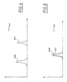
- FIG. 4 shows, in pictorial form, how an embodiment of the present invention which combines the embodiments of FIGs. 1 and 3 utilizes reflections from an eye to generate two radiation signals in sample arm path 1140 which interfere with two radiation signals generated in reference arm path 1070, wherein interference between these two sets of radiation signals can be observed at the same time to measure the eye length.
- the distance L between 50% transmitter and retroreflector 1130 equal to the eye length of an average human eye.
- the first interference signal is generated by interference between radiation in reference arm path 1070 arising from path 1 shown in FIG. 2 and radiation in sample arm path 1140 arising from reflection from the cornea shown in FIG. 4 .
- the second interference signal is generated by interference between radiation in reference arm path 1070 arising from path 2 shown in FIG. 2 and radiation in sample arm path 1140 arising from reflection from the retina shown in FIG. 4 .
- FIG.4 and FIG. 5 show, in graphical form, the two interference signals obtained and displayed on display 1260.
- L the length of an average human eye
- L eye the length of a patient's eye
- both interference signals will be observed with a time delay.
- the length of the eye can be measured by causing motor 1090 to move 50% transmitter 1080, for example, by interaction with computer 1250, so that signals 1600 and 1601 coincide in time as shown in FIG. 5 .
- this movement may be caused by input from an operator using inputs derived from a number of devices (not shown) which are well known to those of ordinary skill in the art such as a joy stick, a mouse and the like.
- computer 1250 may be programmed to overlap the two signals using methods which are well known to those of ordinary skill in the art.
- the position of 50% transmitter 1080 is relayed to computer 1250 from encoder 1100 and computer 1250 uses the position to make the measurement.
- the accuracy of the measurement is the coherence length of the low coherence radiation source 1000.
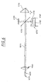
- FIG. 6 shows, in pictorial form, an alternative embodiment of a reference arm for use in embodiment 2000 shown in FIG. 1 .
- 50/50 beamsplitter 4110 splits the incoming radiation in reference arm path 1070 so that it travels over two optical paths.
- the first optical path (a) radiation passes through beamsplitter 4110; (b) is reflected from retroreflector 1130; (c) passes through beamsplitter 4110 again; and (d) passes through collimating lens 1060 as radiation 4210.
- retroreflector 1130 is scanned with a velocity V, so that the Doppler shift frequency is f D for the first optical path.
- the optical pathlength for the first optical path is initially set equal to the optical pathlength of radiation reflected from the cornea of an eye that emerges from sample arm path 1140.
- the second optical path (a) radiation passes through beamsplitter 4110; (b) is reflected from retroreflector 1130; (c) is reflected from beamsplitter 4110 to mirror 4120; (d) is reflected from mirror 4120; (e) passes through beamsplitter 4110; (f) is reflected from mirror 4130 which is mounted on linear stage 4140; (g) is reflected from beamsplitter 4110; and (h) passes through collimating lens 1060 as radiation 4220.
- mirrors 4120 and 4130 can also be retroreflectors like retroreflector 1130. Since the radiation which traverses the second optical path is only reflected from retroreflector 1130 once, the Doppler frequency shift is f D for the second optical path. Then, in accordance with the present invention, the optical distance between mirrors 4120 and 4130 is set to the optical pathlength of an average human eye. As a result, the total optical pathlength traversed by radiation 4220 is equal to the optical pathlength length traversed by the sample beam reflected from the retina.
- motor 4150 moves linear stage translation apparatus 4140 in response to signals sent thereto from computer 1250 so that the location of the interference signal generated by radiation reflected from the cornea and the location of the interference signal generated by radiation reflected from the retina coincide in the manner described above.
- the position of mirror 4130 is relayed to computer 1250 by encoder 4160.
- the eye length information is obtained from the optical pathlength between mirrors 4120 and 4130.
- a calibration procedure can precisely determine the length measurement.
- An advantage of this alternative embodiment is that only a single channel bandpass filter in the detector electronics is required since the same Doppler frequency is generated for each of the reference arm signals 4210 and 4220.
- embodiments of the present invention can be used to measure the distance between two parts of an object.
- embodiments of the present invention may be fabricated utilizing discrete optical components, integrated optics, optical fibers and combinations of the same.
- other embodiments may utilize couplers and transmitters that differ from the 50% coupler and 50% transmitters described above and, in light of the descriptions above, it should be clear to those of ordinary skill in the art how the above-described embodiments may be altered to account for such differences.
Description
- The present invention relates to optical coherence tomography ("OCT") and, in particular, to method and apparatus for OCT which includes an interferometer that enables high resolution measurement with selective measurement ranges.
- It is well known in the prior art to incorporate low coherence optical interferometers into various optical coherence tomography ("OCT") apparatus to study scattering media. A basic form of such an OCT apparatus found in the prior art comprises an interferometer that includes a 50/50 beamsplitter, or a 3 dB coupler if the interferometer is embodied using optical fibers. In a typical prior art optical fiber embodiment of the OCT apparatus, a low coherence radiation source and a photodetector are coupled to two input ends of the 3 dB coupler. The beams of radiation transmitted from two output ends of the 3 dB coupler are transmitted to a sample medium to be tested and a reference medium, respectively. The beams from the output ends are: (a) reflected from the sample medium and the reference medium, respectively; (b) combined by the 3 dB coupler; and (c) transmitted to the photodetector. As is well known in the prior art, when the optical pathlength mismatch between radiation reflected from the sample medium and radiation reflected from the reference medium is less than the coherence length of the low coherence radiation source, measurable interference occurs between these the two beams. Then, if the optical pathlength of the radiation reflected from the reference medium is known, when the photodetector senses the interference signals, the optical pathlength of the radiation reflected from the sample medium can be measured to the accuracy of the coherence length of the radiation source.
- It is also known in the prior art to utilize OCT methods and apparatus to investigate the eye. In doing so, several types of apparatus have been used to provide a reference medium to facilitate measurement of the optical pathlength of radiation reflected from the reference medium. For example, an OCT apparatus disclosed in an article entitled "Optical Coherence Tomography" by David Huang et al., Science, Vol. 254, pp. 1178-1181, Nov. 22, 1991 utilized a mirror to reflect a reference beam back to a photodetector. In the disclosed OCT apparatus, depth information for radiation reflected by the sample medium is acquired on a step-by-step basis by moving the mirror with a stepper motor. The disclosed OCT apparatus has been modified in the art, for example, see
U.S. Patent No. 5,321,501 .U.S. Patent No. 5,321,501 discloses: (a) the use of a retroreflector instead of the mirror to improve the optical alignment stability and (b) the use of a galvanometer instead of the stepper motor to increase the scan speed. The increased scan speed is important because it makes it feasible to obtain tomographical images of living tissue. In this regard, in vivo human eye retinal tomography has been demonstrated in an article entitled "In vivo retinal imaging by optical coherence tomography" by Eric Swanson, et al., Optics Letters, Vol. 18, No. 21, pp. 1864-1866, November 1, 1993. A disadvantage of such OCT apparatus is that the depth measurement is limited to about 3 mm to 5 mm for in vivo human eye measurement. - An article entitled "Coherent optical tomography of microscopic inhomogeneities in biological tissues" by V. M. Gelikonov et al., JETP Lett., Vol. 61, No. 2, pp. 158-162, January 25, 1995 disclosed the use of a piezoelectric radial actuator with a fixed mirror in the reference arm of an interferometer to fabricate an OCT apparatus. In this OCT apparatus, the optical pathlength of the reference arm is modulated by applying a signal to the piezoelectric actuator, thereby stretching the optical fiber longitudinally. In this arrangement, although the scan speed can be improved, the scan depth is still limited. Further, stretching an optical fiber to increase the scan depth causes other problems such as birefringence and hysteresis.
- In light of the above, there is a need for a method and apparatus for simply and economically providing efficient scanning in an OCT apparatus.
- In addition to the above, there is a need to utilize the efficient scanning apparatus to perform eye length measurements. At present, eye length measurements are made by measuring the delay of an ultrasound echo back from the retina. Due to the attenuation of ultrasound energy in the eye, only low frequency ultrasound energy can be used. As a result, the accuracy is typically only about 200 µm. This accuracy represents a measurement error for refraction of approximately ½ diopter and is considered significant in clinical applications such as cataract surgery. Further, this measurement technique suffers because the method requires contact with the eye (this is not comfortable for a patient).
- In light of the above, there is a need in the art for method and apparatus for accurately measuring the length of an eye, preferably in a non-contact mode.
- An article entitled "Optical Measurement of the Axial Eye Length by Laser Doppler Interferometry" by C. K. Hitzenberger, Investigative Ophthalmology & Visual Science, Vol. 32, No. 3, March 3, 1991, pp. 616-624 discloses the use of dual beam Michelson interferometry to measure the eye length using a low coherence light source. The disadvantage of the disclosed configuration is that a bifocal lens is required to focus the beams on the cornea and the retina separately. If this were not done, the signal strength is too weak for imaging the retina. Embodiments of the present invention provide an alternative interferometer configuration to measure eye length without physically increasing the reference beam scan length. In addition, such embodiments are capable of scanning the retinal image with a good signal to noise ratio.
- Advantageously, embodiments of the present invention are method and apparatus for simply and economically providing efficient scanning in an optical coherence tomography ("OCT") apparatus. In particular, an embodiment of the present invention is an OCT apparatus according to
claims 1 or 4. -
-
FIG. 1 shows, in pictorial form, an embodiment of an OCT apparatus which is fabricated in accordance with the present invention; -
FIG. 2 shows, in pictorial form, shows two of many possible paths for radiation traversing a reference arm path of the embodiment of the present invention shown inFIG. 1 ; -
FIG. 3 is a diagram of a signal analysis section of an OCT apparatus which is fabricated in accordance with the present invention, which OCT apparatus is adapted to measuring the length of an eye; -
FIG. 4 and -
FIG. 5 show, in graphical form, two interference signals generated in accordance with the present invention to measure the length of an eye; and -
FIG. 6 shows, in pictorial form, an alternative embodiment of the reference arm of the OCT apparatus shown inFIG. 1 . -
FIG. 1 shows, in pictorial form,embodiment 2000 of the present invention that is used to investigate sample objects. As shown inFIG. 1 ,embodiment 2000 of the present invention is comprised of a lowcoherence radiation source 1000. Lowcoherence radiation source 1000 may be embodied in a number of ways which are well known to those of ordinary skill in the art. In a preferred embodiment of the present invention, shortcoherence radiation source 1000 is a superluminescent diode (SLD). Radiation output from lowcoherence radiation source 1000 is applied overoptical fiber 1010 as input to 3dB radiation coupler 1030. 3dB radiation coupler 1030 couples 50% of the radiation input thereto from lowcoherence radiation source 1000 intooptical fibers dB radiation coupler 1030 may be embodied in a number of ways which are well known to those of ordinary skill in the art. In a preferred embodiment of the present invention, 3dB radiation coupler 1030 is an optical fiber radiation coupler. Radiation output fromoptical fibers lens systems 1065 and 1067, respectively, intoreference arm path 1070 and sample arm path 1140 ofembodiment 2000, respectively. - As further shown in
FIG. 1 , radiation inreference arm path 1070 impinges upon measurementrange variation apparatus 1111. In particular, radiation inreference arm path 1070 impinges upon, and propagates through, 50% transmitter 1080 ( for example, a 50% mirror). As shown inFIG. 1 , 50%transmitter 1080 is mounted on linearstage translation apparatus 1090 andencoder 1100 provides a precise determination of the position of linearstage translation apparatus 1090. Linearstage translation apparatus 1090 andencoder 1100 may be embodied in a number of ways which are well known to those of ordinary skill in the art. As shown inFIG. 1 ,encoder 1100 is affixed to linearstage translation apparatus 1090. In accordance with the present invention, linearstage translation apparatus 1090 is driven bymotor 1120 so thatdistance 1110 between 50%transmitter 1080 andretroreflector 1130 can be adjusted. In addition,retroreflector 1130 is translated at constant speed V back and forth through a distance d, which distance d will be referred to below as a scan range d. The translation ofretroreflector 1130 may be accomplished in a number of ways which are well known to those of ordinary skill in the art. In a preferred embodiment of the present invention,high speed galvanometer 1135 is affixed toretroreflector 1130 to provide the desired translation. - Radiation in sample arm path 1140 impinges upon and propagates through
transverse scanning apparatus 1160. Radiation output fromtransverse scanning apparatus 1160 is focused by focusinglens system 1150 ontosample 1105. As is well known to those of ordinary skill in the art,transverse scanning apparatus 1160 provides a two dimensional transverse scan of radiation in sample arm path 1140 oversample 1105. Further,transverse scanning apparatus 1160 may be embodied in a number of ways which are well known to those of ordinary skill in the art. - Radiation transmitted back into
reference arm path 1070 through 50% transmitter 1080 and radiation transmitted back into sample arm path 1140 throughtransverse scanning apparatus 1160 is applied as input by collimatinglens systems 1065 and 1067, respectively, intooptical fibers optical fibers dB radiation coupler 1030. 3dB radiation coupler 1030, in turn, combines radiation coupled thereinto fromreference arm path 1070 and sample arm path 1140 and couples the combined radiation intooptical fiber 1020. It should be understood that although the present invention has been described in the context of an embodiment which utilizes optical fibers, the present invention is not limited thereto and further embodiments may be readily fabricated by those of ordinary skill in the art using discrete optical components as well as integrated optics. - Radiation output from
optical fiber 1020 is applied as input tophotodetector 1170. As is well known to those of ordinary skill in the art, when the mismatch between the optical pathlength between radiation combined in 3dB radiation coupler 1030 fromreference arm path 1070 and sample arm path 1140 is less than the coherence length ofradiation source 1000, a measurably useful interference signal is output fromphotodetector 1170. In accordance withembodiment 2000 of the present invention, the interference signal output fromphotodetector 1170 is applied as input totransimpedance amplifier 1180. Output fromtransimpedance amplifier 1180 is applied as input tomixer 1200 along with a signal generated by tunablelocal oscillator 1190.Photodetector 1170,transimpedance amplifier 1180, tunablelocal oscillator 1190, andmixer 1200 may be embodied in a number of ways which are well known to those of ordinary skill in the art. - As is well known to those of ordinary skill in the art, since
retroreflector 1130 is scanned back and forth at a constant speed V, the interference signal output from photodetector, and hence the signal applied as input tomixer 1200 fromtransimpedance amplifier 1180 is modulated with a Doppler shift frequency fD where:

where: (i) λ = wavelength of the radiation output from lowcoherence radiation source 1000; (ii) V is the effective velocity of the scan; (iii) d is the scan range ofretroreflector 1130; and (iv) t is the scan time. - As is well known to those of ordinary skill in the art,
mixer 1200, together withlocal oscillator 1190, functions like a frequency converter widely used in AM/FM receivers to generate a signal having an intermediate frequency fi, where fi= fo - fD (fo is the frequency of local oscillator 1190). It is well known thatmixer 1200 also produces a number of frequencies, for example, fo + fD. Although the higher frequency produces a better signal-to-noise ratio, amplifier bandwidths are more limited at higher frequencies. - In accordance with
embodiment 2000 of the present invention, the signal output frommixer 1200 is applied as input tobandpass filter 1215, the passband ofbandpass filter 1215 being centered at fi. The signal output frombandpass filter 1215 is applied as input to logamplifier 1220 which serves both as a rectifier and as a logarithmic amplifier to convert the signal envelop of the input signal to a logarithm scale signal. The bandwidth of the signal at the intermediate frequency fi is proportional to the spectral bandwidth of the signal output from low coherence radiation source 1000 (Δfj = 2πcΔλ/λ2, where c equals the speed of light). The bandwidth ofbandpass filter 1215 is selected to be broad enough to allow substantially all of the signal components to pass through, yet the bandwidth is selected to be as narrow as possible to eliminate most of the noise. - The signal output from
log amplifier 1220 is applied as input tolowpass filter 1230 and output fromlowpass filter 1230, in turn, is applied as input to A/D converter 1240. A/D converter 1240 converts the input signal to a digital signal and the digital signal output from A/D converter 1240 is applied as input tocomputer 1250.Computer 1250 processes the raw signal, for example, to measure the eye length and to display the processed results ondisplay monitor 1260, for example, using a color map.Bandpass filter 1215,log amplifier 1220,lowpass filter 1230, A/D converter 1240,computer 1250, and display monitor 1260 may be embodied in a number of ways which are well known to those of ordinary skill in the art. -
FIG. 2 shows, in pictorial form, two of many possible optical paths for radiation traversingreference arm path 1070 ofembodiment 2000 of the present invention shown inFIG. 1 . Forpath 1 ofFIG. 2 , the maximum and minimum of optical pathlength traversed between 50% transmitter 1080 andretroreflector 1130 is equal to 2(L ± d/2), respectively (where L is the distance between 50% transmitter 1080 and the midpoint of translation ofretroreflector 1130 and d is thetotal distance retroreflector 1130 is translated, i.e., the scan range of retroreflector 1130). Forpath 1, the Doppler frequency of the interference signal output from photodetector 1170 fD1 = fD (where fD is the value provided by eqn. (1) above). Forpath 2 ofFIG. 2 , radiation bounces back and forth between 50% transmitter 1080 andretroreflector 1130 twice before passing through 50% transmitter 1080 back to collimatinglens system 1065. Thus, forpath 2, the maximum and minimum of optical pathlength traversed between 50% transmitter 1080 andretroreflector 1130 is equal to 4(L ± d/2), respectively. Using eqn. (2) above, the effective velocity of the scan ofretroreflector 1130 is equal to 2V. As a result, forpath 2, the Doppler frequency of the interference signal output from photodetector 1170 fD2 = 2fD. - As one can readily appreciate, if
bandpass filter 1215 is centered at fi = fo - fD to pass a signal generated bypath 1, the intermediate frequency fi2 (= fo - 2fD) of the signal output frommixer 1200 forpath 2 will not pass throughbandpass filter 1215. In this case, therefore, as should be readily understood by those of ordinary skill in the art, a longitudinal scan intosample 1105 with depth d can be observed. However, if the frequency of tunablelocal oscillator 1190 is tuned at fO2 (= fo + fD), the intermediate frequency fi2 (= fo + fD - 2fD = fo - fD = f¡) will pass throughbandpass filter 1215 and a longitudinal scan intosample 1105 with depth 2d can be observed. - Generalizing from the above, and in accordance with the present invention, for the embodiment of the present invention shown in
FIG. 1 , if the frequency of tunablelocal oscillator 1190 is tuned at fON (= fo + (N - 1)fD), the intermediate frequency fiN, (= fo + (N-1)fD- NfD = fo - fD = fi) will pass throughbandpass filter 1215 and a longitudinal scan intosample 1105 with depth Nd can be observed. - However, since the intensity of radiation coupled back to 3 dB radiation coupler from
reference arm path 1070 will be reduced by 0.5(0.5R)N, where R is the reflectance ofretroreflector 1130, the potential scan depth range may be limited by the number of bounces between 50% transmitter 1080 andretroreflector 1130. The reflectance of a solid glass retroreflector which is based on total internal reflection and which has an anti-reflection coating on the face side can have a value of R higher than 0.9. An additional concern is that for a shot noise limited system, radiation output fromreference arm path 1070 signal is preferably kept larger than radiation output from sample arm path 1140. In particular, for ophthalmic applications of embodiments of the present invention, since the reflectance of an eye is less than 10-4 of the incident radiation intensity, N can be as large as 4 to 5. -
FIG. 3 is a diagram of a signal analysis section of an OCT apparatus which is fabricated in accordance with the present invention, which OCT apparatus is adapted to measuring the length of an eye. The signal analysis section shown inFIG. 3 replaces the signal analysis section shown inFIG. 1 which is comprised of circuit elements betweentransimpedance amplifier 1180 and A/D 1240. For the following, assume that two signals have been received byphotodetector 1170, one of the two signals corresponds topath 1 ofFIG. 2 and the second of the two signals corresponds topath 2 ofFIG. 2 . - As shown in
FIG. 3 , the two signals are applied as input tophotodetector 1170. The output fromphotodetector 1170 is applied as input totransimpedance amplifier 1180, and the output fromtransimpedance amplifier 1180 is applied, in turn, as input tobandpass filters Bandpass filters FIG. 3 ,bandpass filters transimpedance amplifier 1180 andmultiplexer 1193. -
FIG. 4 shows, in pictorial form, how an embodiment of the present invention which combines the embodiments ofFIGs. 1 and3 utilizes reflections from an eye to generate two radiation signals in sample arm path 1140 which interfere with two radiation signals generated inreference arm path 1070, wherein interference between these two sets of radiation signals can be observed at the same time to measure the eye length. To do this, one selects the distance L between 50% transmitter andretroreflector 1130 equal to the eye length of an average human eye. Now, referring toFIG. 4 , the first signal generated in sample arm path 1140 results from reflection of radiation from the cornea of the eye and the second signal generated in sample arm path 1140 results from reflection of radiation from the retina of the eye. Then, as one can readily appreciate, the first interference signal is generated by interference between radiation inreference arm path 1070 arising frompath 1 shown inFIG. 2 and radiation in sample arm path 1140 arising from reflection from the cornea shown inFIG. 4 . Similarly, the second interference signal is generated by interference between radiation inreference arm path 1070 arising frompath 2 shown inFIG. 2 and radiation in sample arm path 1140 arising from reflection from the retina shown inFIG. 4 . -
FIG.4 and FIG. 5 show, in graphical form, the two interference signals obtained and displayed ondisplay 1260. As shown inFIG. 4 and FIG. 5 , bysignals motor 1090 to move 50% transmitter 1080, for example, by interaction withcomputer 1250, so thatsignals FIG. 5 . As can be readily appreciated, this movement may be caused by input from an operator using inputs derived from a number of devices (not shown) which are well known to those of ordinary skill in the art such as a joy stick, a mouse and the like. Alternatively,computer 1250 may be programmed to overlap the two signals using methods which are well known to those of ordinary skill in the art. The position of 50% transmitter 1080 is relayed tocomputer 1250 fromencoder 1100 andcomputer 1250 uses the position to make the measurement. Advantageously, in accordance with the present invention, the accuracy of the measurement is the coherence length of the lowcoherence radiation source 1000. -
FIG. 6 shows, in pictorial form, an alternative embodiment of a reference arm for use inembodiment 2000 shown inFIG. 1 . As shown inFIG. 6 , 50/50beamsplitter 4110 splits the incoming radiation inreference arm path 1070 so that it travels over two optical paths. In the first optical path: (a) radiation passes throughbeamsplitter 4110; (b) is reflected fromretroreflector 1130; (c) passes throughbeamsplitter 4110 again; and (d) passes throughcollimating lens 1060 asradiation 4210. In this embodiment,retroreflector 1130 is scanned with a velocity V, so that the Doppler shift frequency is fD for the first optical path. For this embodiment, the optical pathlength for the first optical path is initially set equal to the optical pathlength of radiation reflected from the cornea of an eye that emerges from sample arm path 1140. In the second optical path: (a) radiation passes throughbeamsplitter 4110; (b) is reflected fromretroreflector 1130; (c) is reflected frombeamsplitter 4110 tomirror 4120; (d) is reflected frommirror 4120; (e) passes throughbeamsplitter 4110; (f) is reflected frommirror 4130 which is mounted onlinear stage 4140; (g) is reflected frombeamsplitter 4110; and (h) passes throughcollimating lens 1060 asradiation 4220. It should be understood that mirrors 4120 and 4130 can also be retroreflectors likeretroreflector 1130. Since the radiation which traverses the second optical path is only reflected fromretroreflector 1130 once, the Doppler frequency shift is fD for the second optical path. Then, in accordance with the present invention, the optical distance betweenmirrors radiation 4220 is equal to the optical pathlength length traversed by the sample beam reflected from the retina. Further, in accordance with the present invention,motor 4150 moves linearstage translation apparatus 4140 in response to signals sent thereto fromcomputer 1250 so that the location of the interference signal generated by radiation reflected from the cornea and the location of the interference signal generated by radiation reflected from the retina coincide in the manner described above. The position ofmirror 4130 is relayed tocomputer 1250 byencoder 4160. In this manner, the eye length information is obtained from the optical pathlength betweenmirrors reference arm signals - Lastly, although the present invention has been described in terms of measurement of the length of a human eye, the present invention is not so limited. In fact, as can readily be appreciated by those of ordinary skill in the art, embodiments of the present invention can be used to measure the distance between two parts of an object. Further, embodiments of the present invention may be fabricated utilizing discrete optical components, integrated optics, optical fibers and combinations of the same. Still further, other embodiments may utilize couplers and transmitters that differ from the 50% coupler and 50% transmitters described above and, in light of the descriptions above, it should be clear to those of ordinary skill in the art how the above-described embodiments may be altered to account for such differences.
Claims (14)
- An optical coherence tomography apparatus ("OCT") for examining an object (1105), which OCT apparatus comprises:- a source of short coherence radiation (1000);- a coupler (1030) which is arranged:• for coupling a first portion of the radiation to a reference arm path (1070);• for coupling a second portion of the radiation to a sample arm path (1140);• for combining radiation transmitted thereto from the reference path and the sample path; and• for coupling the combined radiation to an analyzer;- a measurement range variation apparatus (1111),wherein:- the reference arm path (1070) transmits the first portion of the radiation to said measurement range variation apparatus (1111) and transmits radiation output from the measurement range variation apparatus back to the coupler (1030);- the sample path (1140) transmits the second portion of the radiation to the object (1105) and transmits radiation scattered by the object back to the coupler 1030); and- the measurement range variation apparatus (1111) comprises:the OCT apparatus being characterised in that• a transmitter (1080) for transmitting a portion of the radiation incident thereupon;• a first reflector (1130) for reflecting radiation transmitted by the transmitter (1080); and• a scanner coupled to scan the first reflector (1130).- said transmitter (1080) is arranged for causing radiation• bouncing back and forth between said transmitter (1080) and said first reflector (1130) and• being transmitted to said coupler (1030).
- The OCT apparatus of claim 1, characterized by that said transmitter (1080) is mounted on a translation mechanism (1090) for adjusting an optical path length between said transmitter (1080) and said first reflector (1130).
- The OCT apparatus of claim 2, wherein said measurement range variation apparatus (1111) further comprises an encoder (1100) which measures the position of said transmitter (1080).
- An optical coherence tomography apparatus ("OCT") for examining an object (1105), which OCT apparatus comprises:- a source of short coherence radiation (1000);- a coupler (1030) which is arranged:• for coupling a first portion of the radiation to a reference arm path (1070);• for coupling a second portion of the radiation to a sample arm path (1140);• for combining radiation transmitted thereto from the reference path and the sample path; and• for coupling the combined radiation to an analyzer;- a measurement range variation apparatus (1111) comprising a first reflector (1130) and a scanner coupled to scan the first reflector (1130),wherein:- the reference arm path (1070) transmits the first portion of the radiation to a measurement range variation apparatus (1111) and transmits radiation output from the measurement range variation apparatus back to the coupler (1030);- the sample path (1140) transmits the second portion of the radiation to the object (1105) and transmits radiation scattered by the object back to the coupler (1030);the OCT apparatus being characterised in that- the measurement range variation apparatus (1111) further comprises:the beamsplitter is also arranged for directing and passing radiation which is reflected from said first reflector (1130) via said second reflector (4120) and said third reflector (4130) to said coupler (1030).• a beamsplitter (4110) arranged in said reference arm path (1070) for transmitting a portion of the radiation incident thereupon in a direction from the reference arm path to said first reflector (1130); a second reflector (4120) and a third reflector (4130) disposed to reflect radiation incident thereupon along a second direction, wherein
- The OCT apparatus of claim 4, characterized by that said third reflector (4130) being mounted on a translation mechanism (4140) for adjusting an optical path length between said second mirror (4140) and said analyzer.
- The OCT apparatus of claim 6 wherein the measurement range variation apparatus (1111) further comprises an encoder (1100) for measuring the position of said third reflector (4130).
- The OCT apparatus as in one of the claims 1 to 6 wherein said analyzer comprises: a photodetector (1170) for detecting radiation coupled from the coupler; a mixer (1200) responsive to output from the photodetector (1170) and an oscillator (1190); and a filter (1215) coupled to the output from the mixer (1200).
- The OCT apparatus of claim 7 characterized in said filter (1215) having a passband centered substantially at a frequency proportional to a Doppler shift frequency produced by scanning the first reflector (1130).
- The OCT apparatus of claim 7 wherein said oscillator (1190) is a tunable oscillator.
- The OCT apparatus as in one of the claims 1 to 6 wherein the analyzer comprises: a photodetector (1170) for detecting radiation coupled from the coupler (1030), a first filter (1183) coupled to output from the photodetector (1170) and having a passband centered substantially at a frequency proportional to a Doppler shift frequency produced by scanning the reflector (1130), and a second filter (1187) coupled to the output from the photodetector (1170) having a passband centered substantially at a multiple of that frequency.
- The OCT apparatus as in one of the preceding claims wherein said analyzer comprises a display (1260) for displaying a signal generated as a result of radiation scattered from a first scattering portion and a signal generated as a result of radiation scattered from a second scattering portion.
- The OCT apparatus of claim 2, 3 and 11, or 5, 6 and 11, wherein said analyzer further comprises a computer for sending a signal to the translation mechanism (1090, 4140) to cause the two signals to coincide and for receiving a signal from said encoder (1100) to provide thereby a measurement of the distance.
- The OCT apparatus as in one of the preceding claims wherein said first reflector is a retroreflector (1130).
- Using the OCT apparatus as in one of the claims 1 to 13 for examining an object.
Applications Claiming Priority (2)
| Application Number | Priority Date | Filing Date | Title |
|---|---|---|---|
| US79908 | 1998-05-15 | ||
| US09/079,908 US6053613A (en) | 1998-05-15 | 1998-05-15 | Optical coherence tomography with new interferometer |
Publications (2)
| Publication Number | Publication Date |
|---|---|
| EP0956809A1 EP0956809A1 (en) | 1999-11-17 |
| EP0956809B1 true EP0956809B1 (en) | 2008-12-17 |
Family
ID=22153581
Family Applications (1)
| Application Number | Title | Priority Date | Filing Date |
|---|---|---|---|
| EP99105995A Expired - Lifetime EP0956809B1 (en) | 1998-05-15 | 1999-03-25 | Interferometer for optical coherence tomography |
Country Status (4)
| Country | Link |
|---|---|
| US (1) | US6053613A (en) |
| EP (1) | EP0956809B1 (en) |
| JP (1) | JP4423450B2 (en) |
| DE (1) | DE69940087D1 (en) |
Cited By (2)
| Publication number | Priority date | Publication date | Assignee | Title |
|---|---|---|---|---|
| CN101617196B (en) * | 2007-02-21 | 2012-07-04 | 爱克发医疗保健公司 | System and method for optical coherence tomography and method for calibrating said type of system |
| CN101617193B (en) * | 2007-02-21 | 2013-09-18 | 爱克发医疗保健公司 | System and method for optical coherence tomography |
Families Citing this family (202)
| Publication number | Priority date | Publication date | Assignee | Title |
|---|---|---|---|---|
| US6615072B1 (en) | 1999-02-04 | 2003-09-02 | Olympus Optical Co., Ltd. | Optical imaging device |
| DE10020559A1 (en) * | 2000-04-27 | 2001-10-31 | Hannover Laser Zentrum | Laser cutting device e.g. for laser surgery, uses ultra short laser pulses with duration of less than 300 picoseconds |
| DE10042751A1 (en) * | 2000-08-31 | 2002-03-14 | Thomas Hellmuth | System for the contactless measurement of the optical image quality of an eye |
| EP1432960A2 (en) | 2000-09-04 | 2004-06-30 | Forskningscenter Riso | Optical amplification in coherence reflectometry |
| JP4241038B2 (en) * | 2000-10-30 | 2009-03-18 | ザ ジェネラル ホスピタル コーポレーション | Optical method and system for tissue analysis |
| US9295391B1 (en) | 2000-11-10 | 2016-03-29 | The General Hospital Corporation | Spectrally encoded miniature endoscopic imaging probe |
| CA2448527C (en) * | 2001-03-20 | 2008-12-02 | Cornell Research Foundation, Inc. | Precision ultrasound measurement for intraocular lens placement |
| EP2333523B1 (en) * | 2001-04-30 | 2020-04-08 | The General Hospital Corporation | Method and apparatus for improving image clarity and sensitivity in optical coherence tomography using dynamic feedback to control focal properties and coherence gating |
| US7865231B2 (en) | 2001-05-01 | 2011-01-04 | The General Hospital Corporation | Method and apparatus for determination of atherosclerotic plaque type by measurement of tissue optical properties |
| DE10151216A1 (en) * | 2001-10-16 | 2003-04-24 | Zeiss Carl Jena Gmbh | Method for the optical detection of characteristic quantities of an illuminated sample |
| US6980299B1 (en) | 2001-10-16 | 2005-12-27 | General Hospital Corporation | Systems and methods for imaging a sample |
| WO2003060423A2 (en) * | 2002-01-11 | 2003-07-24 | The General Hospital Corporation | Apparatus for low coherence ranging |
| US7747315B2 (en) * | 2002-01-15 | 2010-06-29 | Board Of Regents, The University Of Texas System | Methods and compositions to reduce scattering of light during therapeutic and diagnostic imaging procedures |
| US7355716B2 (en) * | 2002-01-24 | 2008-04-08 | The General Hospital Corporation | Apparatus and method for ranging and noise reduction of low coherence interferometry LCI and optical coherence tomography OCT signals by parallel detection of spectral bands |
| US20110201924A1 (en) * | 2002-04-30 | 2011-08-18 | The General Hospital Corporation | Method and Apparatus for Improving Image Clarity and Sensitivity in Optical Tomography Using Dynamic Feedback to Control Focal Properties and Coherence Gating |
| US8054468B2 (en) | 2003-01-24 | 2011-11-08 | The General Hospital Corporation | Apparatus and method for ranging and noise reduction of low coherence interferometry LCI and optical coherence tomography OCT signals by parallel detection of spectral bands |
| WO2004088361A2 (en) | 2003-03-31 | 2004-10-14 | The General Hospital Corporation | Speckle reduction in optical coherence tomography by path length encoded angular compounding |
| EP2319405B1 (en) * | 2003-01-24 | 2013-09-18 | The General Hospital Corporation | System and method for identifying tissue using low-coherence interferometry |
| WO2004073501A2 (en) * | 2003-02-20 | 2004-09-02 | Gutin Mikhail | Optical coherence tomography with 3d coherence scanning |
| US6988801B2 (en) * | 2003-03-25 | 2006-01-24 | University Of Rochester | Compact portable wavefront sensor |
| RU2247938C1 (en) * | 2003-05-27 | 2005-03-10 | Геликонов Валентин Михайлович | Optical device for object analysis |
| TWI223719B (en) * | 2003-05-30 | 2004-11-11 | Ind Tech Res Inst | Sub-micrometer-resolution optical coherent tomography |
| KR101386971B1 (en) * | 2003-06-06 | 2014-04-18 | 더 제너럴 하스피탈 코포레이션 | Process and apparatus for a wavelength tunning source |
| US7876974B2 (en) * | 2003-08-29 | 2011-01-25 | Vladimir Brajovic | Method for improving digital images and an image sensor for sensing the same |
| US7733497B2 (en) | 2003-10-27 | 2010-06-08 | The General Hospital Corporation | Method and apparatus for performing optical imaging using frequency-domain interferometry |
| EP1687587B1 (en) * | 2003-11-28 | 2020-01-08 | The General Hospital Corporation | Method and apparatus for three-dimensional spectrally encoded imaging |
| AT501056B1 (en) * | 2004-02-06 | 2007-04-15 | Zeiss Carl Meditec Ag | SHORT COHERENCE INTERFEROMETRICAL LENGTH MEASUREMENT AT THE EYE |
| WO2005077256A1 (en) * | 2004-02-06 | 2005-08-25 | Optovue, Inc. | Optical apparatus and methods for performing eye examinations |
| CA2553761A1 (en) * | 2004-02-10 | 2005-08-25 | Optovue, Inc. | High efficiency low coherence interferometry |
| US7474408B2 (en) * | 2004-05-14 | 2009-01-06 | Medeikon Corporation | Low coherence interferometry utilizing phase |
| US7184148B2 (en) | 2004-05-14 | 2007-02-27 | Medeikon Corporation | Low coherence interferometry utilizing phase |
| US7327463B2 (en) | 2004-05-14 | 2008-02-05 | Medrikon Corporation | Low coherence interferometry utilizing magnitude |
| US20050254059A1 (en) * | 2004-05-14 | 2005-11-17 | Alphonse Gerard A | Low coherence interferometric system for optical metrology |
| US7242480B2 (en) * | 2004-05-14 | 2007-07-10 | Medeikon Corporation | Low coherence interferometry for detecting and characterizing plaques |
| US7190464B2 (en) * | 2004-05-14 | 2007-03-13 | Medeikon Corporation | Low coherence interferometry for detecting and characterizing plaques |
| AU2004320269B2 (en) | 2004-05-29 | 2011-07-21 | The General Hospital Corporation | Process, system and software arrangement for a chromatic dispersion compensation using reflective layers in optical coherence tomography (OCT) imaging |
| WO2006014392A1 (en) | 2004-07-02 | 2006-02-09 | The General Hospital Corporation | Endoscopic imaging probe comprising dual clad fibre |
| US8081316B2 (en) * | 2004-08-06 | 2011-12-20 | The General Hospital Corporation | Process, system and software arrangement for determining at least one location in a sample using an optical coherence tomography |
| WO2006024014A2 (en) | 2004-08-24 | 2006-03-02 | The General Hospital Corporation | Process, system and software arrangement for measuring a mechanical strain and elastic properties of a sample |
| US8208995B2 (en) | 2004-08-24 | 2012-06-26 | The General Hospital Corporation | Method and apparatus for imaging of vessel segments |
| US7365859B2 (en) * | 2004-09-10 | 2008-04-29 | The General Hospital Corporation | System and method for optical coherence imaging |
| EP2329759B1 (en) | 2004-09-29 | 2014-03-12 | The General Hospital Corporation | System and method for optical coherence imaging |
| JP5175101B2 (en) * | 2004-10-29 | 2013-04-03 | ザ ジェネラル ホスピタル コーポレイション | System and method for performing Jones matrix based analysis to measure unpolarized polarization parameters using polarization sensitive optical coherence tomography |
| JP5623692B2 (en) * | 2004-11-02 | 2014-11-12 | ザ ジェネラル ホスピタル コーポレイション | Optical fiber rotator, optical system and method for sample imaging |
| US7995210B2 (en) * | 2004-11-24 | 2011-08-09 | The General Hospital Corporation | Devices and arrangements for performing coherence range imaging using a common path interferometer |
| JP2008521516A (en) | 2004-11-29 | 2008-06-26 | ザ ジェネラル ホスピタル コーポレイション | Configuration, apparatus, endoscope, catheter, and method for performing optical image generation by simultaneously illuminating and detecting multiple points on a sample |
| US8394084B2 (en) | 2005-01-10 | 2013-03-12 | Optimedica Corporation | Apparatus for patterned plasma-mediated laser trephination of the lens capsule and three dimensional phaco-segmentation |
| US7809171B2 (en) * | 2005-01-10 | 2010-10-05 | Battelle Memorial Institute | Facial feature evaluation based on eye location |
| WO2006078802A1 (en) * | 2005-01-21 | 2006-07-27 | Massachusetts Institute Of Technology | Methods and apparatus for optical coherence tomography scanning |
| EP2325803A1 (en) | 2005-04-28 | 2011-05-25 | The General Hospital Corporation | Evaluating optical coherence tomography information for an anatomical structure |
| EP1887926B1 (en) * | 2005-05-31 | 2014-07-30 | The General Hospital Corporation | System and method which use spectral encoding heterodyne interferometry techniques for imaging |
| US9060689B2 (en) | 2005-06-01 | 2015-06-23 | The General Hospital Corporation | Apparatus, method and system for performing phase-resolved optical frequency domain imaging |
| US7426036B2 (en) * | 2005-07-08 | 2008-09-16 | Imalux Corporation | Common path frequency domain optical coherence reflectometer and common path frequency domain optical coherence tomography device |
| ES2354287T3 (en) | 2005-08-09 | 2011-03-11 | The General Hospital Corporation | APPARATUS AND METHOD FOR PERFORMING A DEMODULATION IN QUADRATURE BY POLARIZATION IN OPTICAL COHERENCE TOMOGRAPHY. |
| CN101365375B (en) | 2005-09-29 | 2013-09-11 | 通用医疗公司 | Method and apparatus for optical imaging via spectral encoding |
| US7400410B2 (en) | 2005-10-05 | 2008-07-15 | Carl Zeiss Meditec, Inc. | Optical coherence tomography for eye-length measurement |
| US7889348B2 (en) * | 2005-10-14 | 2011-02-15 | The General Hospital Corporation | Arrangements and methods for facilitating photoluminescence imaging |
| DE102005059923A1 (en) * | 2005-12-13 | 2007-06-14 | Oculus Optikgeräte GmbH | Eye tissue surface measuring point determining method, involves deriving length of optical path through measuring point to light sensor from measured value of frequency and specific light speed on basis of impulse light source |
| DE102005062238A1 (en) * | 2005-12-22 | 2007-07-05 | Carl Zeiss Meditec Ag | Ophthalmological measurement system for measuring biometric eye data has evaluation unit that uses measurement values of optical measurement device and/or ultrasonic measurement device to determine biometric data of an eye |
| EP1971848B1 (en) | 2006-01-10 | 2019-12-04 | The General Hospital Corporation | Systems and methods for generating data based on one or more spectrally-encoded endoscopy techniques |
| PL1973466T3 (en) | 2006-01-19 | 2021-07-05 | The General Hospital Corporation | Ballon imaging catheter |
| US20070223006A1 (en) * | 2006-01-19 | 2007-09-27 | The General Hospital Corporation | Systems and methods for performing rapid fluorescence lifetime, excitation and emission spectral measurements |
| US8145018B2 (en) | 2006-01-19 | 2012-03-27 | The General Hospital Corporation | Apparatus for obtaining information for a structure using spectrally-encoded endoscopy techniques and methods for producing one or more optical arrangements |
| WO2007084959A1 (en) * | 2006-01-20 | 2007-07-26 | The General Hospital Corporation | Systems and methods for providing mirror tunnel microscopy |
| JP5524487B2 (en) * | 2006-02-01 | 2014-06-18 | ザ ジェネラル ホスピタル コーポレイション | A method and system for emitting electromagnetic radiation to at least a portion of a sample using a conformal laser treatment procedure. |
| WO2007149603A2 (en) | 2006-02-01 | 2007-12-27 | The General Hospital Corporation | Apparatus for applying a plurality of electro-magnetic radiations to a sample |
| JP5519152B2 (en) | 2006-02-08 | 2014-06-11 | ザ ジェネラル ホスピタル コーポレイション | Device for acquiring information about anatomical samples using optical microscopy |
| EP1987318B1 (en) | 2006-02-24 | 2015-08-12 | The General Hospital Corporation | Methods and systems for performing angle-resolved fourier-domain optical coherence tomography |
| WO2007103721A2 (en) * | 2006-03-01 | 2007-09-13 | The General Hospital Corporation | System and method for providing cell specific laser therapy of atherosclerotic plaques by targeting light absorbers in macrophages |
| WO2007109540A2 (en) * | 2006-03-17 | 2007-09-27 | The General Hospital Corporation | Arrangement, method and computer-accessible medium for identifying characteristics of at least a portion of a blood vessel contained within a tissue using spectral domain low coherence interferometry |
| JP5135324B2 (en) * | 2006-04-05 | 2013-02-06 | ザ ジェネラル ホスピタル コーポレイション | Method, arrangement and system for polarization sensitive optical frequency domain imaging of samples |
| EP2517616A3 (en) * | 2006-05-10 | 2013-03-06 | The General Hospital Corporation | Processes, arrangements and systems for providing frequency domain imaging of a sample |
| WO2007133964A2 (en) * | 2006-05-12 | 2007-11-22 | The General Hospital Corporation | Processes, arrangements and systems for providing a fiber layer thickness map based on optical coherence tomography images |
| JP4907227B2 (en) * | 2006-05-29 | 2012-03-28 | 株式会社ニデック | Intraocular dimension measuring device |
| US7488930B2 (en) * | 2006-06-02 | 2009-02-10 | Medeikon Corporation | Multi-channel low coherence interferometer |
| CN101589301B (en) | 2006-08-25 | 2012-11-07 | 通用医疗公司 | Apparatus and methods for enhancing optical coherence tomography imaging using volumetric filtering techniques |
| US7452077B2 (en) * | 2006-08-29 | 2008-11-18 | Carl Zeiss Meditec, Inc. | Image adjustment derived from optical imaging measurement data |
| WO2008049118A2 (en) | 2006-10-19 | 2008-04-24 | The General Hospital Corporation | Apparatus and method for obtaining and providing imaging information associated with at least one portion of a sample and effecting such portion(s) |
| US20080206804A1 (en) * | 2007-01-19 | 2008-08-28 | The General Hospital Corporation | Arrangements and methods for multidimensional multiplexed luminescence imaging and diagnosis |
| US7949019B2 (en) | 2007-01-19 | 2011-05-24 | The General Hospital | Wavelength tuning source based on a rotatable reflector |
| US7911621B2 (en) | 2007-01-19 | 2011-03-22 | The General Hospital Corporation | Apparatus and method for controlling ranging depth in optical frequency domain imaging |
| EP1962052B1 (en) | 2007-02-21 | 2010-07-14 | Agfa HealthCare N.V. | System and method for optical coherence tomography |
| EP1962081B1 (en) | 2007-02-21 | 2016-09-14 | Agfa HealthCare N.V. | System for optical coherence tomography |
| EP2339329A3 (en) | 2007-02-21 | 2012-04-04 | Agfa HealthCare N.V. | System and method for optical coherence tomography |
| EP1962080B1 (en) | 2007-02-21 | 2011-06-01 | Agfa HealthCare N.V. | System for optical coherence tomography |
| EP1962079B1 (en) | 2007-02-21 | 2016-06-01 | Agfa HealthCare N.V. | System and method for optical coherence tomography |
| EP1962051A1 (en) | 2007-02-21 | 2008-08-27 | Agfa HealthCare N.V. | System and method for optical coherence tomography |
| EP3308756B1 (en) | 2007-03-13 | 2020-02-19 | Optimedica Corporation | Apparatus for creating incisions to improve intraocular lens placement |
| WO2008116010A1 (en) * | 2007-03-19 | 2008-09-25 | The General Hospital Corporation | System and method for providing noninvasive diagnosis of compartment syndrome exemplary laser speckle imaging procedure |
| EP2602651A3 (en) | 2007-03-23 | 2014-08-27 | The General Hospital Corporation | Methods, arrangements and apparatus for utilizing a wavelength-swept laser using angular scanning and dispersion procedures |
| US10534129B2 (en) | 2007-03-30 | 2020-01-14 | The General Hospital Corporation | System and method providing intracoronary laser speckle imaging for the detection of vulnerable plaque |
| DE102007016444A1 (en) * | 2007-04-05 | 2008-10-16 | Precitec Optronik Gmbh | processing device |
| WO2008131082A1 (en) | 2007-04-17 | 2008-10-30 | The General Hospital Corporation | Apparatus and methods for measuring vibrations using spectrally-encoded endoscopy techniques |
| US8115919B2 (en) | 2007-05-04 | 2012-02-14 | The General Hospital Corporation | Methods, arrangements and systems for obtaining information associated with a sample using optical microscopy |
| JP5917803B2 (en) * | 2007-07-31 | 2016-05-18 | ザ ジェネラル ホスピタル コーポレイション | System and method for emitting a beam scanning pattern for fast Doppler optical frequency domain imaging |
| EP2191254B1 (en) | 2007-08-31 | 2017-07-19 | The General Hospital Corporation | System and method for self-interference fluorescence microscopy, and computer-accessible medium associated therewith |
| US8076624B1 (en) | 2007-09-19 | 2011-12-13 | Barchers Jeffrey D | Non-cooperative laser target enhancement system and method |
| US8787774B2 (en) * | 2007-10-10 | 2014-07-22 | Luxtera, Inc. | Method and system for a narrowband, non-linear optoelectronic receiver |
| WO2009059034A1 (en) * | 2007-10-30 | 2009-05-07 | The General Hospital Corporation | System and method for cladding mode detection |
| US7800759B2 (en) * | 2007-12-11 | 2010-09-21 | Bausch & Lomb Incorporated | Eye length measurement apparatus |
| PL2230990T3 (en) * | 2007-12-21 | 2017-08-31 | Bausch & Lomb Incorporated | Ophthalmic instrument alignment apparatus and method of using same |
| JP2011508651A (en) | 2008-01-02 | 2011-03-17 | アークスキャン インコーポレイテッド | Imaging device, ultrasonic arc scanning device, and ultrasonic scanning device |
| US10531859B2 (en) | 2008-01-02 | 2020-01-14 | Arcscan, Inc. | Components for a precision ultrasonic scanning apparatus for body parts |
| US20090225324A1 (en) * | 2008-01-17 | 2009-09-10 | The General Hospital Corporation | Apparatus for providing endoscopic high-speed optical coherence tomography |
| US9332942B2 (en) * | 2008-01-28 | 2016-05-10 | The General Hospital Corporation | Systems, processes and computer-accessible medium for providing hybrid flourescence and optical coherence tomography imaging |
| US11123047B2 (en) | 2008-01-28 | 2021-09-21 | The General Hospital Corporation | Hybrid systems and methods for multi-modal acquisition of intravascular imaging data and counteracting the effects of signal absorption in blood |
| US10426348B2 (en) | 2008-03-05 | 2019-10-01 | Purdue Research Foundation | Using differential time-frequency tissue-response spectroscopy to evaluate living body response to a drug |
| WO2011160064A1 (en) * | 2010-06-17 | 2011-12-22 | Purdue Research Foundation | Digital holographic method of measuring cellular activity and of using results to screen compounds |
| US20140276681A1 (en) | 2013-03-15 | 2014-09-18 | Optimedica Corporation | Microfemtotomy methods and systems |
| US10080684B2 (en) | 2008-03-13 | 2018-09-25 | Optimedica Corporation | System and method for laser corneal incisions for keratoplasty procedures |
| WO2009124271A1 (en) | 2008-04-03 | 2009-10-08 | Arcscan, Inc. | Procedures for an ultrasonic arc scanning apparatus |
| EP2296531B1 (en) * | 2008-04-23 | 2017-12-27 | Bioptigen, Inc. | Optical coherence tomography (oct) imaging systems for use in pediatric ophthalmic applications and related methods and computer program products |
| EP2274572A4 (en) | 2008-05-07 | 2013-08-28 | Gen Hospital Corp | System, method and computer-accessible medium for tracking vessel motion during three-dimensional coronary artery microscopy |
| WO2009146434A1 (en) * | 2008-05-29 | 2009-12-03 | Arcscan, Inc. | Compound scanning head for an ultrasonic scanning apparatus |
| WO2009155536A2 (en) | 2008-06-20 | 2009-12-23 | The General Hospital Corporation | Fused fiber optic coupler arrangement and method for use thereof |
| WO2010009136A2 (en) | 2008-07-14 | 2010-01-21 | The General Hospital Corporation | Apparatus and methods for color endoscopy |
| JP5731394B2 (en) | 2008-12-10 | 2015-06-10 | ザ ジェネラル ホスピタル コーポレイション | System, apparatus and method for extending imaging depth range of optical coherence tomography through optical subsampling |
| CA2784538C (en) | 2008-12-15 | 2016-12-06 | Arc-San, Inc. | Alignment and imaging of an eye with an ultrasonic scanner |
| US9149254B2 (en) | 2008-12-15 | 2015-10-06 | Arcscan, Inc. | Alignment and imaging of an eye with an ultrasonic scanner |
| US8294971B2 (en) * | 2008-12-18 | 2012-10-23 | Bausch • Lomb Incorporated | Apparatus comprising an optical path delay scanner |
| WO2010085775A2 (en) | 2009-01-26 | 2010-07-29 | The General Hospital Corporation | System, method and computer-accessible medium for providing wide-field superresolution microscopy |
| CN102308444B (en) | 2009-02-04 | 2014-06-18 | 通用医疗公司 | Apparatus and method for utilization of a high-speed optical wavelength tuning source |
| JP5249073B2 (en) * | 2009-02-12 | 2013-07-31 | 株式会社ニデック | Optical interference type distance measuring device |
| US9351642B2 (en) | 2009-03-12 | 2016-05-31 | The General Hospital Corporation | Non-contact optical system, computer-accessible medium and method for measurement at least one mechanical property of tissue using coherent speckle technique(s) |
| JP5258052B2 (en) * | 2009-04-25 | 2013-08-07 | 国立大学法人宇都宮大学 | Shape measuring method and shape measuring device by phase shift method, complex amplitude measuring method and complex amplitude measuring device |
| JP5545618B2 (en) * | 2009-07-06 | 2014-07-09 | 株式会社ニデック | Eye size measuring device |
| BR112012001042A2 (en) | 2009-07-14 | 2016-11-22 | Gen Hospital Corp | fluid flow measurement equipment and method within anatomical structure. |
| US8510883B2 (en) * | 2009-10-30 | 2013-08-20 | Arcscan, Inc. | Method of positioning a patient for medical procedures |
| US20110184395A1 (en) * | 2009-12-23 | 2011-07-28 | Optimedica Corporation | Method for laser capsulotomy and lens conditioning |
| EP3138475B1 (en) * | 2010-01-22 | 2023-10-25 | AMO Development, LLC | Apparatus for automated placement of scanned laser capsulorhexis incisions |
| WO2011097647A1 (en) | 2010-02-08 | 2011-08-11 | Optimedica Corporation | System for plasma-mediated modification of tissue |
| ES2831223T3 (en) | 2010-03-05 | 2021-06-07 | Massachusetts Gen Hospital | Apparatus for providing electromagnetic radiation to a sample |
| US9069130B2 (en) | 2010-05-03 | 2015-06-30 | The General Hospital Corporation | Apparatus, method and system for generating optical radiation from biological gain media |
| US9557154B2 (en) | 2010-05-25 | 2017-01-31 | The General Hospital Corporation | Systems, devices, methods, apparatus and computer-accessible media for providing optical imaging of structures and compositions |
| US9795301B2 (en) | 2010-05-25 | 2017-10-24 | The General Hospital Corporation | Apparatus, systems, methods and computer-accessible medium for spectral analysis of optical coherence tomography images |
| EP2575591A4 (en) | 2010-06-03 | 2017-09-13 | The General Hospital Corporation | Apparatus and method for devices for imaging structures in or at one or more luminal organs |
| US10401793B2 (en) | 2010-06-17 | 2019-09-03 | Purdue Research Foundation | Digital holographic method of measuring cellular activity and measuring apparatus with improved stability |
| US9510758B2 (en) | 2010-10-27 | 2016-12-06 | The General Hospital Corporation | Apparatus, systems and methods for measuring blood pressure within at least one vessel |
| US8437007B2 (en) | 2010-12-30 | 2013-05-07 | Axsun Technologies, Inc. | Integrated optical coherence tomography system |
| US9046337B2 (en) | 2010-12-30 | 2015-06-02 | Volcano Corporation | Integrated OCT detector system with transimpedance amplifier |
| CA2826799C (en) * | 2011-02-15 | 2017-11-14 | Wavelight Gmbh | System and method for measuring internal dimensions of an object by optical coherence tomography |
| WO2012149175A1 (en) | 2011-04-29 | 2012-11-01 | The General Hospital Corporation | Means for determining depth-resolved physical and/or optical properties of scattering media |
| WO2013013049A1 (en) | 2011-07-19 | 2013-01-24 | The General Hospital Corporation | Systems, methods, apparatus and computer-accessible-medium for providing polarization-mode dispersion compensation in optical coherence tomography |
| US10241028B2 (en) | 2011-08-25 | 2019-03-26 | The General Hospital Corporation | Methods, systems, arrangements and computer-accessible medium for providing micro-optical coherence tomography procedures |
| EP2769491A4 (en) | 2011-10-18 | 2015-07-22 | Gen Hospital Corp | Apparatus and methods for producing and/or providing recirculating optical delay(s) |
| ITPI20120009A1 (en) * | 2012-01-24 | 2013-07-25 | Visia Imaging S R L | "A METHOD TO REDUCE THE TIME OF THE MEASUREMENT TO SCANNING THE EYE AXIAL LENGTH AND DEVICE TO IMPLEMENT THIS METHOD" |
| WO2013148306A1 (en) | 2012-03-30 | 2013-10-03 | The General Hospital Corporation | Imaging system, method and distal attachment for multidirectional field of view endoscopy |
| US9597059B2 (en) | 2012-05-17 | 2017-03-21 | Arcscan, Inc. | Correcting for unintended motion for ultrasonic eye scans |
| WO2013177154A1 (en) | 2012-05-21 | 2013-11-28 | The General Hospital Corporation | Apparatus, device and method for capsule microscopy |
| US9320427B2 (en) | 2012-07-09 | 2016-04-26 | Arcscan, Inc. | Combination optical and ultrasonic imaging of an eye |
| JP6227652B2 (en) | 2012-08-22 | 2017-11-08 | ザ ジェネラル ホスピタル コーポレイション | System, method, and computer-accessible medium for fabricating a miniature endoscope using soft lithography |
| US10702209B2 (en) | 2012-10-24 | 2020-07-07 | Amo Development, Llc | Graphical user interface for laser eye surgery system |
| US10285860B2 (en) | 2012-11-02 | 2019-05-14 | Optimedica Corporation | Vacuum loss detection during laser eye surgery |
| US9445946B2 (en) | 2012-11-02 | 2016-09-20 | Optimedica Corporation | Laser eye surgery system |
| US9987165B2 (en) | 2012-11-02 | 2018-06-05 | Optimedica Corporation | Liquid optical interface for laser eye surgery system |
| US10314746B2 (en) | 2012-11-02 | 2019-06-11 | Optimedica Corporation | Laser eye surgery system calibration |
| US9549670B2 (en) | 2012-11-02 | 2017-01-24 | Optimedica Corporation | Optical surface identification for laser surgery |
| US10278862B2 (en) | 2012-11-02 | 2019-05-07 | Optimedica Corporation | Low voltage communication between subsystems in a laser eye surgery system |
| US10292863B2 (en) | 2012-11-02 | 2019-05-21 | Optimedica Corporation | Interface force feedback in a laser eye surgery system |
| US10624786B2 (en) | 2012-11-02 | 2020-04-21 | Amo Development, Llc | Monitoring laser pulse energy in a laser eye surgery system |
| WO2014085911A1 (en) | 2012-12-05 | 2014-06-12 | Tornado Medical Systems, Inc. | System and method for wide field oct imaging |
| WO2014120791A1 (en) | 2013-01-29 | 2014-08-07 | The General Hospital Corporation | Apparatus, systems and methods for providing information regarding the aortic valve |
| US11179028B2 (en) | 2013-02-01 | 2021-11-23 | The General Hospital Corporation | Objective lens arrangement for confocal endomicroscopy |
| EP2967999B1 (en) | 2013-03-14 | 2017-04-19 | Optimedica Corporation | Laser capsulovitreotomy |
| JP6378311B2 (en) | 2013-03-15 | 2018-08-22 | ザ ジェネラル ホスピタル コーポレイション | Methods and systems for characterizing objects |
| US10369053B2 (en) | 2013-04-17 | 2019-08-06 | Optimedica Corporation | Corneal topography measurements and fiducial mark incisions in laser surgical procedures |
| EP3505145B1 (en) | 2013-04-17 | 2020-08-19 | Optimedica Corporation | Laser fiducials for axis alignment in cataract surgery |
| EP2986259B1 (en) | 2013-04-18 | 2019-09-11 | Optimedica Corporation | Corneal topography measurement and alignment of corneal surgical procedures |
| WO2014186353A1 (en) | 2013-05-13 | 2014-11-20 | The General Hospital Corporation | Detecting self-interefering fluorescence phase and amplitude |
| WO2015009932A1 (en) | 2013-07-19 | 2015-01-22 | The General Hospital Corporation | Imaging apparatus and method which utilizes multidirectional field of view endoscopy |
| EP3021735A4 (en) | 2013-07-19 | 2017-04-19 | The General Hospital Corporation | Determining eye motion by imaging retina. with feedback |
| AU2014293542B2 (en) | 2013-07-25 | 2019-03-14 | Amo Development, Llc | In situ determination of refractive index of materials |
| EP3025173B1 (en) | 2013-07-26 | 2021-07-07 | The General Hospital Corporation | Apparatus with a laser arrangement utilizing optical dispersion for applications in fourier-domain optical coherence tomography |
| US9918873B2 (en) | 2013-10-08 | 2018-03-20 | Optimedica Corporation | Laser eye surgery system calibration |
| US9733460B2 (en) | 2014-01-08 | 2017-08-15 | The General Hospital Corporation | Method and apparatus for microscopic imaging |
| WO2015116986A2 (en) | 2014-01-31 | 2015-08-06 | The General Hospital Corporation | System and method for facilitating manual and/or automatic volumetric imaging with real-time tension or force feedback using a tethered imaging device |
| JP6580580B2 (en) | 2014-02-04 | 2019-09-25 | オプティメディカ コーポレイション | System and method for laser keratotomy for corneal transplantation |
| WO2015127417A1 (en) | 2014-02-24 | 2015-08-27 | Arcscan, Inc. | Disposable eyepiece system for an ultrasonic eye scanning apparatus |
| WO2015153982A1 (en) | 2014-04-04 | 2015-10-08 | The General Hospital Corporation | Apparatus and method for controlling propagation and/or transmission of electromagnetic radiation in flexible waveguide(s) |
| WO2016015052A1 (en) | 2014-07-25 | 2016-01-28 | The General Hospital Corporation | Apparatus, devices and methods for in vivo imaging and diagnosis |
| AU2015320309B2 (en) | 2014-09-25 | 2020-07-23 | Amo Development, Llc | Methods and systems for corneal topography, blink detection and laser eye surgery |
| JP6808618B2 (en) | 2014-10-17 | 2021-01-06 | オプティメディカ・コーポレイションOptimedica Corporation | Automatic patient positioning for laser eye surgery system |
| CA2964800A1 (en) | 2014-10-17 | 2016-04-21 | Optimedica Corporation | Vacuum loss detection during laser eye surgery |
| EP3270840B1 (en) | 2015-03-18 | 2019-06-05 | Optimedica Corporation | Vacuum loss detection during laser eye surgery |
| CA2991479A1 (en) | 2015-07-08 | 2017-01-12 | Optimedica Corporation | Image processing method and system for edge detection and laser eye surgery system incorporating the same |
| WO2017066460A1 (en) | 2015-10-13 | 2017-04-20 | Arcscan, Inc | Ultrasonic scanning apparatus |
| US11426611B2 (en) | 2015-10-13 | 2022-08-30 | Arcscan, Inc. | Ultrasound therapeutic and scanning apparatus |
| CA3023432C (en) | 2016-05-10 | 2021-05-04 | Optimedica Corporation | Laser eye surgery systems and methods of treating vitreous and ocular floaters |
| DE102016110005A1 (en) * | 2016-05-31 | 2017-11-30 | Universität Zu Lübeck | Device for refractive power change of the cornea |
| EP3628282B1 (en) | 2016-09-14 | 2022-10-19 | AMO Development, LLC | Free floating patient interface for laser surgery system |
| WO2018052455A1 (en) | 2016-09-19 | 2018-03-22 | Optimedica Corporation | Systems for opthalmic measurements and laser surgery and systems for surgical planning based thereon |
| EP3558091A4 (en) | 2016-12-21 | 2020-12-02 | Acucela, Inc. | Miniaturized mobile, low cost optical coherence tomography system for home based ophthalmic applications |
| EP3655748B1 (en) | 2017-07-18 | 2023-08-09 | Perimeter Medical Imaging, Inc. | Sample container for stabilizing and aligning excised biological tissue samples for ex vivo analysis |
| CA3103899A1 (en) | 2018-06-20 | 2019-12-26 | Acucela Inc. | Miniaturized mobile, low cost optical coherence tomography system for home based ophthalmic applications |
| US20200038241A1 (en) | 2018-08-02 | 2020-02-06 | Optimedica Corporation | Full depth laser ophthalmic surgical system, methods of calibrating the surgical system and treatment methods using the same |
| US11000413B2 (en) | 2019-02-15 | 2021-05-11 | Amo Development, Llc | Ophthalmic laser surgical system and method implementing simultaneous laser treatment and OCT measurement |
| JP2023508946A (en) | 2019-12-26 | 2023-03-06 | アキュセラ インコーポレイテッド | Optical Coherence Tomography Patient Alignment System for Home-Based Ophthalmic Applications |
| US10959613B1 (en) | 2020-08-04 | 2021-03-30 | Acucela Inc. | Scan pattern and signal processing for optical coherence tomography |
| US11393094B2 (en) | 2020-09-11 | 2022-07-19 | Acucela Inc. | Artificial intelligence for evaluation of optical coherence tomography images |
| JP2023544704A (en) | 2020-09-30 | 2023-10-25 | アキュセラ インコーポレイテッド | Myopia prediction, diagnosis, planning, and monitoring devices |
| WO2022204622A1 (en) | 2021-03-24 | 2022-09-29 | Acucela Inc. | Axial length measurement monitor |
| DE102021131831A1 (en) | 2021-12-02 | 2022-11-17 | Lessmüller Lasertechnik GmbH | Measuring device for a machining system, machining system and method for adjusting a measuring device for a machining system |
Family Cites Families (6)
| Publication number | Priority date | Publication date | Assignee | Title |
|---|---|---|---|---|
| WO1992019930A1 (en) * | 1991-04-29 | 1992-11-12 | Massachusetts Institute Of Technology | Method and apparatus for optical imaging and measurement |
| US6134003A (en) * | 1991-04-29 | 2000-10-17 | Massachusetts Institute Of Technology | Method and apparatus for performing optical measurements using a fiber optic imaging guidewire, catheter or endoscope |
| US5491524A (en) * | 1994-10-05 | 1996-02-13 | Carl Zeiss, Inc. | Optical coherence tomography corneal mapping apparatus |
| US5644642A (en) * | 1995-04-03 | 1997-07-01 | Carl Zeiss, Inc. | Gaze tracking using optical coherence tomography |
| ATA107495A (en) * | 1995-06-23 | 1996-06-15 | Fercher Adolf Friedrich Dr | COHERENCE BIOMETRY AND TOMOGRAPHY WITH DYNAMIC COHERENT FOCUS |
| US5892583A (en) * | 1997-08-21 | 1999-04-06 | Li; Ming-Chiang | High speed inspection of a sample using superbroad radiation coherent interferometer |
-
1998
- 1998-05-15 US US09/079,908 patent/US6053613A/en not_active Expired - Lifetime
-
1999
- 1999-03-25 EP EP99105995A patent/EP0956809B1/en not_active Expired - Lifetime
- 1999-03-25 DE DE69940087T patent/DE69940087D1/en not_active Expired - Lifetime
- 1999-05-14 JP JP13367099A patent/JP4423450B2/en not_active Expired - Fee Related
Cited By (2)
| Publication number | Priority date | Publication date | Assignee | Title |
|---|---|---|---|---|
| CN101617196B (en) * | 2007-02-21 | 2012-07-04 | 爱克发医疗保健公司 | System and method for optical coherence tomography and method for calibrating said type of system |
| CN101617193B (en) * | 2007-02-21 | 2013-09-18 | 爱克发医疗保健公司 | System and method for optical coherence tomography |
Also Published As
| Publication number | Publication date |
|---|---|
| US6053613A (en) | 2000-04-25 |
| EP0956809A1 (en) | 1999-11-17 |
| DE69940087D1 (en) | 2009-01-29 |
| JP2000002516A (en) | 2000-01-07 |
| JP4423450B2 (en) | 2010-03-03 |
Similar Documents
| Publication | Publication Date | Title |
|---|---|---|
| EP0956809B1 (en) | Interferometer for optical coherence tomography | |
| US7023558B2 (en) | Acousto-optic monitoring and imaging in a depth sensitive manner | |
| US6853457B2 (en) | Optical amplification in coherence reflectometry | |
| EP0581871B2 (en) | Apparatus for optical imaging and measurement | |
| US6900943B2 (en) | Optical amplification in coherent optical frequency modulated continuous wave reflectometry | |
| US5537162A (en) | Method and apparatus for optical coherence tomographic fundus imaging without vignetting | |
| US7061622B2 (en) | Aspects of basic OCT engine technologies for high speed optical coherence tomography and light source and other improvements in optical coherence tomography | |
| EP1782020B1 (en) | Process, system and software arrangement for determining at least one location in a sample using an optical coherence tomography | |
| US7362444B2 (en) | Interferometers for optical coherence domain reflectometry | |
| US6760112B2 (en) | Grin-fiber lens based optical endoscopes | |
| JP5591235B2 (en) | Extended range imaging | |
| EP2278265A2 (en) | Common-Path Interferometer for Endoscopic OCT | |
| CN108572161B (en) | Optical coherence tomography device based on sub-wavefront interferometer | |
| JP6917663B2 (en) | Optical interference unit for optical coherence tomography equipment | |
| CN114869221A (en) | Dispersion-balanced frequency-sweeping OCT (optical coherence tomography) fundus high-resolution imaging system | |
| KR20040039139A (en) | Michelson Interferometer And Optical Coherence Tomography System Using The interferometer | |
| WO2022044204A1 (en) | Optical interference tomographic imaging device | |
| JPH09159607A (en) | Method and equipment for optical heterodyne measurement | |
| JPH0886746A (en) | High-sensitive light wave reflection measuring device and light-wave echo tomographic device using same | |
| JP2021524330A (en) | OCT system and OCT method |
Legal Events
| Date | Code | Title | Description |
|---|---|---|---|
| PUAI | Public reference made under article 153(3) epc to a published international application that has entered the european phase |
Free format text: ORIGINAL CODE: 0009012 |
|
| AK | Designated contracting states |
Kind code of ref document: A1 Designated state(s): DE GB |
|
| AX | Request for extension of the european patent |
Free format text: AL;LT;LV;MK;RO;SI |
|
| 17P | Request for examination filed |
Effective date: 20000429 |
|
| AKX | Designation fees paid |
Free format text: DE GB |
|
| RAP1 | Party data changed (applicant data changed or rights of an application transferred) |
Owner name: CARL ZEISS MEDITEC AG |
|
| 17Q | First examination report despatched |
Effective date: 20060518 |
|
| RIC1 | Information provided on ipc code assigned before grant |
Ipc: G01B 9/02 20060101ALI20080529BHEP Ipc: A61B 5/00 20060101ALI20080529BHEP Ipc: A61B 3/10 20060101AFI20080529BHEP |
|
| GRAP | Despatch of communication of intention to grant a patent |
Free format text: ORIGINAL CODE: EPIDOSNIGR1 |
|
| GRAS | Grant fee paid |
Free format text: ORIGINAL CODE: EPIDOSNIGR3 |
|
| GRAA | (expected) grant |
Free format text: ORIGINAL CODE: 0009210 |
|
| AK | Designated contracting states |
Kind code of ref document: B1 Designated state(s): DE GB |
|
| REG | Reference to a national code |
Ref country code: GB Ref legal event code: FG4D |
|
| REF | Corresponds to: |
Ref document number: 69940087 Country of ref document: DE Date of ref document: 20090129 Kind code of ref document: P |
|
| PLBE | No opposition filed within time limit |
Free format text: ORIGINAL CODE: 0009261 |
|
| STAA | Information on the status of an ep patent application or granted ep patent |
Free format text: STATUS: NO OPPOSITION FILED WITHIN TIME LIMIT |
|
| 26N | No opposition filed |
Effective date: 20090918 |
|
| PGFP | Annual fee paid to national office [announced via postgrant information from national office to epo] |
Ref country code: GB Payment date: 20100322 Year of fee payment: 12 |
|
| PGFP | Annual fee paid to national office [announced via postgrant information from national office to epo] |
Ref country code: DE Payment date: 20100324 Year of fee payment: 12 |
|
| GBPC | Gb: european patent ceased through non-payment of renewal fee |
Effective date: 20110325 |
|
| PG25 | Lapsed in a contracting state [announced via postgrant information from national office to epo] |
Ref country code: DE Free format text: LAPSE BECAUSE OF NON-PAYMENT OF DUE FEES Effective date: 20111001 |
|
| REG | Reference to a national code |
Ref country code: DE Ref legal event code: R119 Ref document number: 69940087 Country of ref document: DE Effective date: 20111001 |
|
| PG25 | Lapsed in a contracting state [announced via postgrant information from national office to epo] |
Ref country code: GB Free format text: LAPSE BECAUSE OF NON-PAYMENT OF DUE FEES Effective date: 20110325 |