EP0956829A2 - Means for interconnecting two spaced elongated rods of a human spine implant - Google Patents
Means for interconnecting two spaced elongated rods of a human spine implant Download PDFInfo
- Publication number
- EP0956829A2 EP0956829A2 EP99109555A EP99109555A EP0956829A2 EP 0956829 A2 EP0956829 A2 EP 0956829A2 EP 99109555 A EP99109555 A EP 99109555A EP 99109555 A EP99109555 A EP 99109555A EP 0956829 A2 EP0956829 A2 EP 0956829A2
- Authority
- EP
- European Patent Office
- Prior art keywords
- hook
- transverse bar
- mouth
- joint
- locking
- Prior art date
- Legal status (The legal status is an assumption and is not a legal conclusion. Google has not performed a legal analysis and makes no representation as to the accuracy of the status listed.)
- Granted
Links
Images

Classifications
-
- A—HUMAN NECESSITIES
- A61—MEDICAL OR VETERINARY SCIENCE; HYGIENE
- A61B—DIAGNOSIS; SURGERY; IDENTIFICATION
- A61B17/00—Surgical instruments, devices or methods, e.g. tourniquets
- A61B17/56—Surgical instruments or methods for treatment of bones or joints; Devices specially adapted therefor
- A61B17/58—Surgical instruments or methods for treatment of bones or joints; Devices specially adapted therefor for osteosynthesis, e.g. bone plates, screws, setting implements or the like
- A61B17/68—Internal fixation devices, including fasteners and spinal fixators, even if a part thereof projects from the skin
- A61B17/70—Spinal positioners or stabilisers ; Bone stabilisers comprising fluid filler in an implant
- A61B17/7049—Connectors, not bearing on the vertebrae, for linking longitudinal elements together
Definitions
- the invention refers to means for the interconnection of two spaced elongated rods of a human spine implant.
- Such implants normally include pedicle screws which are adapted to be screwed into the pedicle of the vertebras. It is known to interconnect vertebras through such pedicle screws and further suitable means, e.g. elongated rods which are attached to the pedicle screws by suitable fastening means. Frequently, there is the necessity that such elongated rods which normally are extended parallel to each other in accordance with the arrangement of the pedicle screws are to be interconnected through at least one transverse bar. Also to this purpose suitable means are known. The known devices have the disadvantage that the surgeon needs much time to install the connection means. The space between the rods and their position differ significantly, and the accessibility for the application of the interconnection means is restricted.
- Object of the invention is to provide a means for the interconnection of two spaced elongated rods of a human spine implant which is simply structured and allows a quick installation.
- a transverse bar forms a joint with a hook.
- the hook is designed such that it may embrace the elongated rod through its mouth in order to exert a transverse force onto the elongated rod. It is essential to the invention that the hook may attain different positions relative the transverse bar. In a release position the mouth of the hook may freely accommodate an elongated rod and allow the removal thereof. If, however, a relative pivoting of rod and hook into the locking position is effected, it inhibits a release of the rod from the hook. In the most simple manner this can be achieved in that the entrance area of the mouth is narrowed. In order to prevent the hook from pivoting into the release position, locking means are provided which become effective if the hook is pivoted into the locking position.
- connection of such a means to an elongated rod thus takes place in the manner that hook and transverse bar have a predetermined angle relative to each other so that the hook may be conveniently placed onto the elongated rod. Thereafter the elongated rod is pivoted relative to the hook to an extent that the locking position is reached.
- the structure of the link of the joint associated with the bar is such that the elongated rod is clamped within the mouth of the hook more or less.
- the linking of the transverse bar to the hook is preferably such that in the locking position the tensional force at the hook is approximately axially transferred to the transverse bar.
- the narrowing of the entrance portion of the mouth of the hook or the clamping of the elongated rod in the mouth, respectively, can be achieved in that the joint portion associated with the transverse bar has an eccentric surface which faces the mouth of the hook.
- the locking means can include a deformable extension attached to the joint portion connected with the transverse bar.
- the extension cooperates with an edge of the hook when the hook is pivoted into the locking position.
- the locking extension is formed by an arcuate segment of the joint portion which is formed by an arcuate slot in the joint portion.
- the mouth portion of the hook has a throughgoing opening which in the locking position is located approximately at the level of the locking means.
- this gripping means is also formed by a hook having a support portion which includes a passage for the extension of the transverse bar therethrough as well as an axial bore for the accommodation of a set screw.
- the passage is open to the free end of the support portion.
- the thread of the support portion preferably has a saw tooth shape such tat the steeper flank of the thread faces the mouth portion.
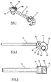
- the means 10 shown in Fig. 1 include a transverse bar 12 substantially rectangular in cross section, a first hook 14 and a second hook 16.
- the first hook 14 is connected to the transverse bar 12 through a joint. This is explained in more detail hereinafter.
- the second hook 16 is rigidly attached to transverse bar 12. It includes a passage to be described herebelow for the accommodation of the transverse bar 12 which by means of a set screw 18 is fixed within the hook 16.
- a disc-shaped joint portion 20 is provided having a throughbore 22.
- the circumferential surface 24 of the joint portion 20 is circular while at 26 an eccentric bulge is provided which in the direction of an arcuate segment 28 is provided with indentation 30.
- the arcuate segment 28 is formed by an arcuate slot 32.
- Hook 14 has a support portion 34 and a mouth portion 36.
- the support portion 34 is fork-shaped and has two spaced legs 38, 40 which both have a throughbore 42.
- the leg portions 39, 40 form a recess 44 adapted to accommodate the disc-shaped joint portion 20, with the throughbores 42, 22 being aligned for the accommodation of a joint pin (not shown).
- the hook portion 36 has a throughbore 48 which is open to recess 44 and extends into the mouth 50 of hook 40.
- a surface 52 is formed by the leg portions 38, 40 of the support portion at the side facing the recess 44. The surface is located on the outer side of the arcuate segment 28 after the assembly of the joint portions. In the assembling position the hook 14 is pivoted upwardly if compared with Figs.
- hook 14 If hook 14 is pivoted relative to transverse bar 12 into the position shown in Figs. 1 and 2 the free end 54 of segment 28 engages behind a shoulder 58 formed by surface 52 and thus locks hook 14 in such a manner that it cannot pivot back.
- the arrangement of the surface 52 is such that upon rotation of the hook segment 28 is slightly deformed radially inwardly so tat it subsequently may engage edge 58.
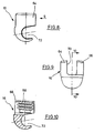
- a second hook 16 is shown in detail.
- hook 16 has two arcuate support portions 64, 66.
- the support portions 64, 66 have threaded portions, one of the threaded portion is shown at 68 in Fig. 10.
- a passage 70 is provided between the support portions 64, 66.
- the passage 70 is opened to the free end of the support portion.
- the passage is adapted to accommodate the transverse bar 12 as shown in Fig. 1.
- a set screw 18 is threaded into the threaded portions 68 in order to fix bar 12 to the hook 16.
- the hook mouth 72 accommodates a second elongated rod not shown without fixing the rod axially.
- the threaded portions 68 are shaped such that one flank of the threads extends substantially perpendicular to the axis, i.e. the flank facing mouth 72. Possibly occurring tensional forces at mouth 22 thus are only transferred as tensional forces to portions 64, 66. Thus, the portions 64, 66 are prevented from being bent away from each other which otherwise may affect the threaded engagement of the set screw 18.
Abstract
Description
Claims (8)
- A means for the interconnection of two spaced elongated rods of a human spine implant, comprising a hook having a mouth and being adapted to partially grip around a first elongated rod, a transverse bar connected to the hook and gripping means adapted to be connected to the second elongated rod and to be attached to the transverse bar, characterized in that transverse bar (12) and hook (14) are interconnected through a joint (20, 38, 40), the joint having joint portions which are adapted to be pivoted between a release position and a locking position, in that further locking means (28, 58) are provided which inhibit a pivoting of the joint portions of the hook to the release position and in that the joint portion (20) connected to the transverse bar (12) is structured such that in the release position the hook with its mouth can be freely placed onto the elongated rod (60) while in the locking position the rod (60) is locked within the mouth.
- The means of claim 1, wherein the joint portion associated with the transverse bar has an eccentric surface (26) facing the mouth (50) of the hook.
- The means of claim 1 or 2, wherein the joint portion (20) associated with the transverse bar has a deformable locking portion (28), an edge (58) of the hook (12) may snap behind said locking portion when the hook is pivoted into the locking position.
- The means of claim 3, wherein the locking portion (28) is shaped as an arcuate segment formed by an arcuate slot.
- The means of claim 1, wherein in the mouth portion (36) hook (12) has a throughgoing opening (58) which in the locking position of hook (12) is located approximately at the level of locking means (28)
- The means of claim 1, wherein the other gripping means includes also a hook (16) the support portion (64, 66) thereof including a passage (70) for the accommodation of the transverse bar (12) and an axial threaded bore (68) for the accommodation of a set screw (18) which cooperates with the transverse bar (12) within the passage.
- The means of claim 6, wherein the passage (70) is open to the free end of the support portion in order to facilitate the insertion of the transverse bar.
- The means of claim 6 or 7, wherein the thread of the support portion (64, 66) has saw tooth-shaped flanks such that the steeper flanks face the hook portion (22).
Applications Claiming Priority (2)
| Application Number | Priority Date | Filing Date | Title |
|---|---|---|---|
| DE29808593U | 1998-05-13 | ||
| DE29808593U DE29808593U1 (en) | 1998-05-13 | 1998-05-13 | Device for connecting two spaced longitudinal rods of a spinal implant |
Publications (3)
| Publication Number | Publication Date |
|---|---|
| EP0956829A2 true EP0956829A2 (en) | 1999-11-17 |
| EP0956829A3 EP0956829A3 (en) | 2002-02-06 |
| EP0956829B1 EP0956829B1 (en) | 2004-04-07 |
Family
ID=8057063
Family Applications (1)
| Application Number | Title | Priority Date | Filing Date |
|---|---|---|---|
| EP99109555A Expired - Lifetime EP0956829B1 (en) | 1998-05-13 | 1999-05-12 | Means for interconnecting two spaced elongated rods of a human spine implant |
Country Status (7)
| Country | Link |
|---|---|
| US (1) | US6096039A (en) |
| EP (1) | EP0956829B1 (en) |
| JP (1) | JP4059364B2 (en) |
| KR (1) | KR19990088224A (en) |
| AU (1) | AU749117B2 (en) |
| CA (1) | CA2271454C (en) |
| DE (2) | DE29808593U1 (en) |
Cited By (13)
| Publication number | Priority date | Publication date | Assignee | Title |
|---|---|---|---|---|
| EP1103226A3 (en) * | 1999-11-29 | 2002-03-20 | Bernd Schäfer | Transverse connector |
| WO2002030307A3 (en) * | 2000-10-06 | 2002-10-03 | Spinal Concepts Inc | Orthopedic transverse connector with cam activated engagers |
| EP1302169A1 (en) * | 2001-10-12 | 2003-04-16 | DePuy Acromed, Inc. | Spinal polyaxial cross connector |
| EP1311199A2 (en) * | 2000-08-18 | 2003-05-21 | Blackstone Medical, Inc. | A surgical cross-connecting apparatus |
| EP1372457A2 (en) * | 2001-04-02 | 2004-01-02 | Endius Incorporated | Polyaxial transverse connector |
| US6872208B1 (en) | 2000-10-06 | 2005-03-29 | Spinal Concepts, Inc. | Adjustable transverse connector |
| US6887241B1 (en) | 2000-10-06 | 2005-05-03 | Spinal Concepts, Inc. | Adjustable transverse connector with cam activated engagers |
| US8556937B2 (en) | 2004-03-31 | 2013-10-15 | DePuy Synthes Products, LLC | Rod attachment for head to head cross connector |
| US8771319B2 (en) | 2012-04-16 | 2014-07-08 | Aesculap Implant Systems, Llc | Rod to rod cross connector |
| US8828056B2 (en) | 2012-04-16 | 2014-09-09 | Aesculap Implant Systems, Llc | Rod to rod cross connector |
| US8870921B2 (en) | 2006-11-08 | 2014-10-28 | DePuy Synthes Products, LLC | Spinal cross connectors |
| US8961572B2 (en) | 2004-08-27 | 2015-02-24 | Depuy Synthes Products Llc | Dual rod cross connectors and inserter tools |
| CN110367804A (en) * | 2019-08-09 | 2019-10-25 | 成玲玲 | A kind of tieback and Pneumatic curtain |
Families Citing this family (79)
| Publication number | Priority date | Publication date | Assignee | Title |
|---|---|---|---|---|
| EP1230902A1 (en) | 1996-11-15 | 2002-08-14 | Advanced Bio Surfaces, Inc. | Biomaterial system for in situ tissue repair |
| EP1743585B1 (en) * | 1999-03-30 | 2007-12-05 | Howmedica Osteonics Corp. | Apparatus for spinal stabilization |
| US6283967B1 (en) * | 1999-12-17 | 2001-09-04 | Synthes (U.S.A.) | Transconnector for coupling spinal rods |
| US6238396B1 (en) * | 1999-10-07 | 2001-05-29 | Blackstone Medical, Inc. | Surgical cross-connecting apparatus and related methods |
| US6217578B1 (en) * | 1999-10-19 | 2001-04-17 | Stryker Spine S.A. | Spinal cross connector |
| EP1244387B1 (en) * | 1999-12-24 | 2005-12-14 | Societe De Fabrication De Materiel Orthopedique Sofamor | Pedicle screws with inclined channels to hold support rods |
| US20060241602A1 (en) * | 2000-06-06 | 2006-10-26 | Jackson Roger P | Hooked transverse connector for spinal implant system |
| US6554831B1 (en) * | 2000-09-01 | 2003-04-29 | Hopital Sainte-Justine | Mobile dynamic system for treating spinal disorder |
| JP2002095672A (en) * | 2000-09-22 | 2002-04-02 | Showa Ika Kohgyo Co Ltd | Instrument for joining bone and its joining component |
| KR100474645B1 (en) * | 2001-06-19 | 2005-03-08 | 쇼와 이카 고교 가부시키가이샤 | Vertebral connecting rod and spinal osteosynthesis device using the same |
| US20030181371A1 (en) * | 2001-12-28 | 2003-09-25 | Angiotech Pharmaceuticals, Inc. | Compositions and methods of using collajolie |
| US7918876B2 (en) | 2003-03-24 | 2011-04-05 | Theken Spine, Llc | Spinal implant adjustment device |
| US7481827B2 (en) * | 2003-10-09 | 2009-01-27 | Synthes (U.S.A.) | Linking transconnector for coupling spinal rods |
| US20050080414A1 (en) * | 2003-10-14 | 2005-04-14 | Keyer Thomas R. | Spinal fixation hooks and method of spinal fixation |
| US7744633B2 (en) | 2003-10-22 | 2010-06-29 | Pioneer Surgical Technology, Inc. | Crosslink for securing spinal rods |
| US7569069B2 (en) * | 2003-12-19 | 2009-08-04 | Orthopaedic International, Inc. | Transverse connector for rod-based spinal implants |
| US7645294B2 (en) | 2004-03-31 | 2010-01-12 | Depuy Spine, Inc. | Head-to-head connector spinal fixation system |
| US7959653B2 (en) * | 2004-09-03 | 2011-06-14 | Lanx, Inc. | Spinal rod cross connector |
| JP2008520383A (en) * | 2004-11-19 | 2008-06-19 | アルファスパイン インコーポレイテッド | Rod connection assembly |
| CN1303943C (en) * | 2005-03-25 | 2007-03-14 | 张英泽 | Pelvis and spinal column position restoring and internal fixing device for treating lumbar vertebrae olisthy olisthe |
| US20060233597A1 (en) * | 2005-04-18 | 2006-10-19 | Ensign Micheal D | Cam based rod connection system and method |
| WO2007114834A1 (en) | 2006-04-05 | 2007-10-11 | Dong Myung Jeon | Multi-axial, double locking bone screw assembly |
| US8043337B2 (en) | 2006-06-14 | 2011-10-25 | Spartek Medical, Inc. | Implant system and method to treat degenerative disorders of the spine |
| US7842071B2 (en) | 2006-07-11 | 2010-11-30 | Pioneer Surgical Technology, Inc. | Transverse connector |
| JP5187594B2 (en) | 2006-09-26 | 2013-04-24 | ジンテス ゲゼルシャフト ミット ベシュレンクテル ハフツング | Transformer connector |
| WO2008045291A2 (en) * | 2006-10-04 | 2008-04-17 | Life Spine, Inc. | Multi-axial spinal cross-connectors |
| US7744632B2 (en) | 2006-12-20 | 2010-06-29 | Aesculap Implant Systems, Inc. | Rod to rod connector |
| US7947066B2 (en) * | 2007-05-22 | 2011-05-24 | K2M, Inc. | Universal transverse connector device |
| US8070776B2 (en) | 2007-06-05 | 2011-12-06 | Spartek Medical, Inc. | Deflection rod system for use with a vertebral fusion implant for dynamic stabilization and motion preservation spinal implantation system and method |
| US8092501B2 (en) | 2007-06-05 | 2012-01-10 | Spartek Medical, Inc. | Dynamic spinal rod and method for dynamic stabilization of the spine |
| US8105359B2 (en) | 2007-06-05 | 2012-01-31 | Spartek Medical, Inc. | Deflection rod system for a dynamic stabilization and motion preservation spinal implantation system and method |
| US8048121B2 (en) | 2007-06-05 | 2011-11-01 | Spartek Medical, Inc. | Spine implant with a defelction rod system anchored to a bone anchor and method |
| US8021396B2 (en) | 2007-06-05 | 2011-09-20 | Spartek Medical, Inc. | Configurable dynamic spinal rod and method for dynamic stabilization of the spine |
| US8083772B2 (en) | 2007-06-05 | 2011-12-27 | Spartek Medical, Inc. | Dynamic spinal rod assembly and method for dynamic stabilization of the spine |
| US8114134B2 (en) | 2007-06-05 | 2012-02-14 | Spartek Medical, Inc. | Spinal prosthesis having a three bar linkage for motion preservation and dynamic stabilization of the spine |
| US8147520B2 (en) | 2007-06-05 | 2012-04-03 | Spartek Medical, Inc. | Horizontally loaded dynamic stabilization and motion preservation spinal implantation system and method |
| US8048115B2 (en) | 2007-06-05 | 2011-11-01 | Spartek Medical, Inc. | Surgical tool and method for implantation of a dynamic bone anchor |
| US8241334B2 (en) * | 2007-07-13 | 2012-08-14 | Life Spine, Inc. | Spinal cross-connector |
| US8048129B2 (en) | 2007-08-15 | 2011-11-01 | Zimmer Spine, Inc. | MIS crosslink apparatus and methods for spinal implant |
| US8430882B2 (en) * | 2007-09-13 | 2013-04-30 | Transcorp, Inc. | Transcorporeal spinal decompression and repair systems and related methods |
| US8603141B2 (en) * | 2007-09-19 | 2013-12-10 | Pioneer Surgical Technology, Inc. | Intervertebral implant devices and methods for insertion thereof |
| AU2008304546A1 (en) | 2007-09-25 | 2009-04-02 | Synthes Gmbh | Transconnector |
| US8080037B2 (en) * | 2008-01-04 | 2011-12-20 | Life Spine, Inc. | Spinal cross-connector with spinal extensor muscle curvature |
| US8097024B2 (en) | 2008-02-26 | 2012-01-17 | Spartek Medical, Inc. | Load-sharing bone anchor having a deflectable post and method for stabilization of the spine |
| US8211155B2 (en) | 2008-02-26 | 2012-07-03 | Spartek Medical, Inc. | Load-sharing bone anchor having a durable compliant member and method for dynamic stabilization of the spine |
| US8267979B2 (en) | 2008-02-26 | 2012-09-18 | Spartek Medical, Inc. | Load-sharing bone anchor having a deflectable post and axial spring and method for dynamic stabilization of the spine |
| US8337536B2 (en) | 2008-02-26 | 2012-12-25 | Spartek Medical, Inc. | Load-sharing bone anchor having a deflectable post with a compliant ring and method for stabilization of the spine |
| US8016861B2 (en) | 2008-02-26 | 2011-09-13 | Spartek Medical, Inc. | Versatile polyaxial connector assembly and method for dynamic stabilization of the spine |
| US8333792B2 (en) | 2008-02-26 | 2012-12-18 | Spartek Medical, Inc. | Load-sharing bone anchor having a deflectable post and method for dynamic stabilization of the spine |
| US8057515B2 (en) | 2008-02-26 | 2011-11-15 | Spartek Medical, Inc. | Load-sharing anchor having a deflectable post and centering spring and method for dynamic stabilization of the spine |
| US8083775B2 (en) | 2008-02-26 | 2011-12-27 | Spartek Medical, Inc. | Load-sharing bone anchor having a natural center of rotation and method for dynamic stabilization of the spine |
| US20100030224A1 (en) | 2008-02-26 | 2010-02-04 | Spartek Medical, Inc. | Surgical tool and method for connecting a dynamic bone anchor and dynamic vertical rod |
| FR2929100B1 (en) * | 2008-03-25 | 2011-04-15 | Medicrea International | VERTEBRAL ARTHRODESIS EQUIPMENT |
| KR101464983B1 (en) | 2008-05-01 | 2014-11-25 | 스파인셀 프러프라이어테리 리미티드 | System methods and apparatuses for formation and insertion of tissue prothesis |
| US8998961B1 (en) | 2009-02-26 | 2015-04-07 | Lanx, Inc. | Spinal rod connector and methods |
| US20100292736A1 (en) * | 2009-05-15 | 2010-11-18 | Warsaw Orthopedic, Inc. | Linkage for Connection of Fusion and Non-Fusion Systems |
| CN101579253B (en) * | 2009-05-27 | 2010-11-17 | 陈哲 | Lumbar spondylolysis restoration internal fixation system |
| CN102695465A (en) | 2009-12-02 | 2012-09-26 | 斯帕泰克医疗股份有限公司 | Low profile spinal prosthesis incorporating a bone anchor having a deflectable post and a compound spinal rod |
| US20110307015A1 (en) | 2010-06-10 | 2011-12-15 | Spartek Medical, Inc. | Adaptive spinal rod and methods for stabilization of the spine |
| US8920471B2 (en) | 2010-07-12 | 2014-12-30 | K2M, Inc. | Transverse connector |
| US8672978B2 (en) | 2011-03-04 | 2014-03-18 | Zimmer Spine, Inc. | Transverse connector |
| US9131963B2 (en) | 2011-03-08 | 2015-09-15 | Life Spine, Inc. | Posterior cross connector assembly |
| US8430916B1 (en) | 2012-02-07 | 2013-04-30 | Spartek Medical, Inc. | Spinal rod connectors, methods of use, and spinal prosthesis incorporating spinal rod connectors |
| US8940020B2 (en) | 2012-04-06 | 2015-01-27 | DePuy Synthes Products, LLC | Rod connector |
| JP6189939B2 (en) * | 2012-05-11 | 2017-08-30 | オーソペディアトリクス・コーポレーション | Surgical couplers and instruments |
| US9707015B2 (en) | 2014-01-14 | 2017-07-18 | Life Spine, Inc. | Implant for immobilizing cervical vertebrae |
| CN105496532A (en) * | 2015-11-27 | 2016-04-20 | 周建明 | Transverse connecting device for internal fixation of spines |
| US20170265904A1 (en) * | 2016-03-16 | 2017-09-21 | Globus Medical, Inc. | Transverse connectors for spinal systems |
| US10575876B2 (en) | 2016-04-20 | 2020-03-03 | K2M, Inc. | Spinal stabilization assemblies with bone hooks |
| US10517647B2 (en) | 2016-05-18 | 2019-12-31 | Medos International Sarl | Implant connectors and related methods |
| US10321939B2 (en) | 2016-05-18 | 2019-06-18 | Medos International Sarl | Implant connectors and related methods |
| US10398476B2 (en) | 2016-12-13 | 2019-09-03 | Medos International Sàrl | Implant adapters and related methods |
| US10492835B2 (en) | 2016-12-19 | 2019-12-03 | Medos International Sàrl | Offset rods, offset rod connectors, and related methods |
| US10238432B2 (en) | 2017-02-10 | 2019-03-26 | Medos International Sàrl | Tandem rod connectors and related methods |
| US10966761B2 (en) | 2017-03-28 | 2021-04-06 | Medos International Sarl | Articulating implant connectors and related methods |
| US10561454B2 (en) | 2017-03-28 | 2020-02-18 | Medos International Sarl | Articulating implant connectors and related methods |
| JP2020533070A (en) | 2017-09-08 | 2020-11-19 | パイオニア サージカル テクノロジー インコーポレイテッド | Intervertebral implants, instruments, and methods |
| USD907771S1 (en) | 2017-10-09 | 2021-01-12 | Pioneer Surgical Technology, Inc. | Intervertebral implant |
| US11076890B2 (en) | 2017-12-01 | 2021-08-03 | Medos International Sàrl | Rod-to-rod connectors having robust rod closure mechanisms and related methods |
Family Cites Families (17)
| Publication number | Priority date | Publication date | Assignee | Title |
|---|---|---|---|---|
| PL114098B1 (en) * | 1978-04-14 | 1981-01-31 | Wyzsza Szkola Inzynierska | Apparatus for correcting spinal curvature |
| US4274401A (en) * | 1978-12-08 | 1981-06-23 | Miskew Don B W | Apparatus for correcting spinal deformities and method for using |
| US4567884A (en) * | 1982-12-01 | 1986-02-04 | Edwards Charles C | Spinal hook |
| US4611582A (en) * | 1983-12-27 | 1986-09-16 | Wisconsin Alumni Research Foundation | Vertebral clamp |
| FR2633177B1 (en) * | 1988-06-24 | 1991-03-08 | Fabrication Materiel Orthopedi | IMPLANT FOR A SPINAL OSTEOSYNTHESIS DEVICE, ESPECIALLY IN TRAUMATOLOGY |
| GB2254394B (en) * | 1988-12-21 | 1993-03-17 | Bristol Myers Squibb Co | Coupler assembly |
| FR2645427A1 (en) * | 1989-04-11 | 1990-10-12 | Cotrel Yves | Transverse fixing bar for spinal osteosynthesis device |
| FR2658413B1 (en) * | 1990-02-19 | 1997-01-03 | Sofamor | OSTEOSYNTHESIS DEVICE FOR THE CORRECTION OF SPINAL DEVIATIONS. |
| FR2659225B1 (en) * | 1990-03-08 | 1995-09-08 | Sofamor | TRANSVERSE FIXING DEVICE FOR PROVIDING A RIGID CROSS-LINK BETWEEN TWO RODS OF A SPINAL OSTEOSYNTHESIS SYSTEM. |
| US5102412A (en) * | 1990-06-19 | 1992-04-07 | Chaim Rogozinski | System for instrumentation of the spine in the treatment of spinal deformities |
| US5034011A (en) * | 1990-08-09 | 1991-07-23 | Advanced Spine Fixation Systems Incorporated | Segmental instrumentation of the posterior spine |
| FR2709411B1 (en) * | 1993-09-03 | 1995-11-17 | Sofamor | Stabilizing forceps of a cervical spinal segment. |
| US5439463A (en) * | 1993-11-12 | 1995-08-08 | Lin; Chih-I | Spinal clamping device |
| US5601552A (en) * | 1994-03-18 | 1997-02-11 | Sofamor, S.N.C. | Fixing device for a rigid transverse connection device between rods of a spinal osteosynthesis system |
| FR2734147B1 (en) * | 1995-05-19 | 1997-10-10 | Klein Jean Michel | IMPLANTABLE OSTEOSYNTHESIS DEVICE |
| FR2745708B1 (en) * | 1996-03-05 | 1998-05-22 | Brienne Ind Sarl | TRANSVERSE SPINAL LINK DEVICE |
| US5800548A (en) * | 1996-03-05 | 1998-09-01 | Bruno Franck | Device for transverse spinal connection |
-
1998
- 1998-05-13 DE DE29808593U patent/DE29808593U1/en not_active Expired - Lifetime
-
1999
- 1999-05-12 KR KR1019990016952A patent/KR19990088224A/en not_active Application Discontinuation
- 1999-05-12 AU AU28101/99A patent/AU749117B2/en not_active Ceased
- 1999-05-12 CA CA002271454A patent/CA2271454C/en not_active Expired - Fee Related
- 1999-05-12 US US09/311,189 patent/US6096039A/en not_active Expired - Lifetime
- 1999-05-12 JP JP13070699A patent/JP4059364B2/en not_active Expired - Fee Related
- 1999-05-12 DE DE69916161T patent/DE69916161T2/en not_active Expired - Lifetime
- 1999-05-12 EP EP99109555A patent/EP0956829B1/en not_active Expired - Lifetime
Non-Patent Citations (1)
| Title |
|---|
| None |
Cited By (23)
| Publication number | Priority date | Publication date | Assignee | Title |
|---|---|---|---|---|
| EP1103226A3 (en) * | 1999-11-29 | 2002-03-20 | Bernd Schäfer | Transverse connector |
| EP1311199A2 (en) * | 2000-08-18 | 2003-05-21 | Blackstone Medical, Inc. | A surgical cross-connecting apparatus |
| EP1311199A4 (en) * | 2000-08-18 | 2006-05-31 | Blackstone Medical Inc | A surgical cross-connecting apparatus |
| US7485132B1 (en) | 2000-10-06 | 2009-02-03 | Abbott Spine Inc. | Transverse connector with cam activated engagers |
| WO2002030307A3 (en) * | 2000-10-06 | 2002-10-03 | Spinal Concepts Inc | Orthopedic transverse connector with cam activated engagers |
| US8062338B2 (en) | 2000-10-06 | 2011-11-22 | Zimmer Spine, Inc. | Transverse connector with cam activated engagers |
| US6872208B1 (en) | 2000-10-06 | 2005-03-29 | Spinal Concepts, Inc. | Adjustable transverse connector |
| US6887241B1 (en) | 2000-10-06 | 2005-05-03 | Spinal Concepts, Inc. | Adjustable transverse connector with cam activated engagers |
| EP1372457A4 (en) * | 2001-04-02 | 2009-11-04 | Endius Inc | Polyaxial transverse connector |
| EP1372457A2 (en) * | 2001-04-02 | 2004-01-02 | Endius Incorporated | Polyaxial transverse connector |
| AU2002301404B2 (en) * | 2001-10-12 | 2008-10-16 | Depuy Spine, Inc. | Polyaxial cross connector |
| EP1302169A1 (en) * | 2001-10-12 | 2003-04-16 | DePuy Acromed, Inc. | Spinal polyaxial cross connector |
| US8556937B2 (en) | 2004-03-31 | 2013-10-15 | DePuy Synthes Products, LLC | Rod attachment for head to head cross connector |
| US9629663B2 (en) | 2004-03-31 | 2017-04-25 | DePuy Synthes Products, Inc. | Rod attachment for head to head cross connector |
| US9486247B2 (en) | 2004-03-31 | 2016-11-08 | DePuy Synthes Products, Inc. | Rod attachment for head to head cross connector |
| US9387014B2 (en) | 2004-03-31 | 2016-07-12 | DePuy Synthes Products, Inc. | Systems and methods for decompressing a spinal canal |
| US8920469B2 (en) | 2004-03-31 | 2014-12-30 | Depuy Synthes Products Llc | Rod attachment for head to head cross connector |
| US8920470B2 (en) | 2004-03-31 | 2014-12-30 | Depuy Synthes Products Llc | Rod attachment for head to head cross connector |
| US8961572B2 (en) | 2004-08-27 | 2015-02-24 | Depuy Synthes Products Llc | Dual rod cross connectors and inserter tools |
| US8870921B2 (en) | 2006-11-08 | 2014-10-28 | DePuy Synthes Products, LLC | Spinal cross connectors |
| US8828056B2 (en) | 2012-04-16 | 2014-09-09 | Aesculap Implant Systems, Llc | Rod to rod cross connector |
| US8771319B2 (en) | 2012-04-16 | 2014-07-08 | Aesculap Implant Systems, Llc | Rod to rod cross connector |
| CN110367804A (en) * | 2019-08-09 | 2019-10-25 | 成玲玲 | A kind of tieback and Pneumatic curtain |
Also Published As
| Publication number | Publication date |
|---|---|
| AU2810199A (en) | 1999-11-25 |
| AU749117B2 (en) | 2002-06-20 |
| CA2271454A1 (en) | 1999-11-13 |
| EP0956829B1 (en) | 2004-04-07 |
| CA2271454C (en) | 2007-08-07 |
| EP0956829A3 (en) | 2002-02-06 |
| DE29808593U1 (en) | 1999-09-23 |
| DE69916161D1 (en) | 2004-05-13 |
| JP2000041989A (en) | 2000-02-15 |
| US6096039A (en) | 2000-08-01 |
| DE69916161T2 (en) | 2005-04-14 |
| JP4059364B2 (en) | 2008-03-12 |
| KR19990088224A (en) | 1999-12-27 |
Similar Documents
| Publication | Publication Date | Title |
|---|---|---|
| EP0956829A2 (en) | Means for interconnecting two spaced elongated rods of a human spine implant | |
| CA2109457C (en) | Osteosynthesis device for spinal consolidation | |
| JP4153299B2 (en) | Spinal implant coupling assembly | |
| EP1101449B1 (en) | A device for stabilizing or, respectively, compressing or distracting portions of the spinal column | |
| US7931650B2 (en) | Adjustable bone stabilizing frame system | |
| US9603636B2 (en) | Transverse connector | |
| US5941881A (en) | Bone fastening apparatus and related procedures | |
| US7235075B1 (en) | Anchoring element for securing a rod on a vertebra | |
| JP3261381B2 (en) | Implants for osteosynthetic devices, especially for spinal column correction | |
| US5067955A (en) | Vertebral implant for osteosynthesis device | |
| KR0150629B1 (en) | Positionable spinal fixation device | |
| US7850719B2 (en) | Spinal implant apparatus | |
| US5976135A (en) | Lateral connector assembly | |
| JP4717280B2 (en) | Bone fixation mechanism | |
| JP2962524B2 (en) | Equipment for stabilizing orthopedic anchors | |
| TWI392473B (en) | Clamp for external fixation | |
| US6866664B2 (en) | Device for releasably clamping a longitudinal member within a surgical implant | |
| US5261909A (en) | Variable angle screw for spinal implant system | |
| EP0425783A1 (en) | Pedicle screw clamp | |
| US8795337B2 (en) | Apparatus for implementing a spinal fixation system with supplemental fixation | |
| EP0929265A2 (en) | A device for fixating and adjusting the positions of vertebrae in vertebral surgical operations | |
| KR20080012851A (en) | Outrigger with locking mechanism | |
| AU2006250290B2 (en) | Spinal implant apparatus | |
| EP0239610A1 (en) | Arrangement relating to a nut for location in an open channel section. | |
| JP2000502932A (en) | Tightening device for screw connection of bone anchor dental implant |
Legal Events
| Date | Code | Title | Description |
|---|---|---|---|
| PUAI | Public reference made under article 153(3) epc to a published international application that has entered the european phase |
Free format text: ORIGINAL CODE: 0009012 |
|
| AK | Designated contracting states |
Kind code of ref document: A2 Designated state(s): AT BE CH CY DE DK ES FI FR GB GR IE IT LI LU MC NL PT SE Kind code of ref document: A2 Designated state(s): CH DE FR GB IT LI |
|
| AX | Request for extension of the european patent |
Free format text: AL;LT;LV;MK;RO;SI |
|
| PUAL | Search report despatched |
Free format text: ORIGINAL CODE: 0009013 |
|
| AK | Designated contracting states |
Kind code of ref document: A3 Designated state(s): AT BE CH CY DE DK ES FI FR GB GR IE IT LI LU MC NL PT SE |
|
| AX | Request for extension of the european patent |
Free format text: AL;LT;LV;MK;RO;SI |
|
| 17P | Request for examination filed |
Effective date: 20020514 |
|
| RAP1 | Party data changed (applicant data changed or rights of an application transferred) |
Owner name: STRYKER TRAUMA GMBH |
|
| AKX | Designation fees paid |
Free format text: CH DE FR GB IT LI |
|
| 17Q | First examination report despatched |
Effective date: 20030321 |
|
| GRAP | Despatch of communication of intention to grant a patent |
Free format text: ORIGINAL CODE: EPIDOSNIGR1 |
|
| GRAS | Grant fee paid |
Free format text: ORIGINAL CODE: EPIDOSNIGR3 |
|
| GRAA | (expected) grant |
Free format text: ORIGINAL CODE: 0009210 |
|
| AK | Designated contracting states |
Kind code of ref document: B1 Designated state(s): CH DE FR GB IT LI |
|
| REG | Reference to a national code |
Ref country code: GB Ref legal event code: FG4D |
|
| REG | Reference to a national code |
Ref country code: CH Ref legal event code: EP |
|
| REF | Corresponds to: |
Ref document number: 69916161 Country of ref document: DE Date of ref document: 20040513 Kind code of ref document: P |
|
| REG | Reference to a national code |
Ref country code: IE Ref legal event code: FG4D |
|
| REG | Reference to a national code |
Ref country code: CH Ref legal event code: NV Representative=s name: ISLER & PEDRAZZINI AG |
|
| ET | Fr: translation filed | ||
| REG | Reference to a national code |
Ref country code: IE Ref legal event code: MM4A |
|
| PLBE | No opposition filed within time limit |
Free format text: ORIGINAL CODE: 0009261 |
|
| STAA | Information on the status of an ep patent application or granted ep patent |
Free format text: STATUS: NO OPPOSITION FILED WITHIN TIME LIMIT |
|
| 26N | No opposition filed |
Effective date: 20050110 |
|
| REG | Reference to a national code |
Ref country code: CH Ref legal event code: PCAR Free format text: ISLER & PEDRAZZINI AG;POSTFACH 1772;8027 ZUERICH (CH) |
|
| PGFP | Annual fee paid to national office [announced via postgrant information from national office to epo] |
Ref country code: IT Payment date: 20070519 Year of fee payment: 9 |
|
| PG25 | Lapsed in a contracting state [announced via postgrant information from national office to epo] |
Ref country code: IT Free format text: LAPSE BECAUSE OF NON-PAYMENT OF DUE FEES Effective date: 20080512 |
|
| REG | Reference to a national code |
Ref country code: FR Ref legal event code: PLFP Year of fee payment: 18 |
|
| REG | Reference to a national code |
Ref country code: CH Ref legal event code: PUE Owner name: STRYKER EUROPEAN HOLDINGS VI, LLC, US Free format text: FORMER OWNER: STRYKER TRAUMA GMBH, DE Ref country code: CH Ref legal event code: PUE Owner name: STRYKER EUROPEAN HOLDINGS I, LLC, US Free format text: FORMER OWNER: STRYKER EUROPEAN HOLDINGS VI, LLC, US |
|
| REG | Reference to a national code |
Ref country code: DE Ref legal event code: R081 Ref document number: 69916161 Country of ref document: DE Owner name: STRYKER EUROPEAN HOLDINGS I, LLC (N.D. GES. D., US Free format text: FORMER OWNER: STRYKER EUROPEAN HOLDINGS VI, LLC (N.D. GES. D. STAATES DELAWARE), KALAMAZOO, MICH., US Ref country code: DE Ref legal event code: R081 Ref document number: 69916161 Country of ref document: DE Owner name: STRYKER EUROPEAN HOLDINGS I, LLC (N.D. GES. D., US Free format text: FORMER OWNER: STRYKER TRAUMA GMBH, 24232 SCHOENKIRCHEN, DE |
|
| PGFP | Annual fee paid to national office [announced via postgrant information from national office to epo] |
Ref country code: GB Payment date: 20160511 Year of fee payment: 18 Ref country code: CH Payment date: 20160511 Year of fee payment: 18 Ref country code: DE Payment date: 20160504 Year of fee payment: 18 |
|
| PGFP | Annual fee paid to national office [announced via postgrant information from national office to epo] |
Ref country code: FR Payment date: 20160412 Year of fee payment: 18 |
|
| REG | Reference to a national code |
Ref country code: GB Ref legal event code: 732E Free format text: REGISTERED BETWEEN 20161006 AND 20161012 |
|
| REG | Reference to a national code |
Ref country code: GB Ref legal event code: 732E Free format text: REGISTERED BETWEEN 20161013 AND 20161019 |
|
| REG | Reference to a national code |
Ref country code: FR Ref legal event code: TP Owner name: STRYKER EUROPEAN HOLDINGS I, LLC, US Effective date: 20161108 |
|
| REG | Reference to a national code |
Ref country code: DE Ref legal event code: R119 Ref document number: 69916161 Country of ref document: DE |
|
| REG | Reference to a national code |
Ref country code: CH Ref legal event code: PL |
|
| GBPC | Gb: european patent ceased through non-payment of renewal fee |
Effective date: 20170512 |
|
| PG25 | Lapsed in a contracting state [announced via postgrant information from national office to epo] |
Ref country code: LI Free format text: LAPSE BECAUSE OF NON-PAYMENT OF DUE FEES Effective date: 20170531 Ref country code: CH Free format text: LAPSE BECAUSE OF NON-PAYMENT OF DUE FEES Effective date: 20170531 |
|
| REG | Reference to a national code |
Ref country code: FR Ref legal event code: ST Effective date: 20180131 |
|
| PG25 | Lapsed in a contracting state [announced via postgrant information from national office to epo] |
Ref country code: DE Free format text: LAPSE BECAUSE OF NON-PAYMENT OF DUE FEES Effective date: 20171201 Ref country code: GB Free format text: LAPSE BECAUSE OF NON-PAYMENT OF DUE FEES Effective date: 20170512 |
|
| PG25 | Lapsed in a contracting state [announced via postgrant information from national office to epo] |
Ref country code: FR Free format text: LAPSE BECAUSE OF NON-PAYMENT OF DUE FEES Effective date: 20170531 |