EP0959382A2 - Photographic camera systems and film cassettes - Google Patents
Photographic camera systems and film cassettes Download PDFInfo
- Publication number
- EP0959382A2 EP0959382A2 EP99115811A EP99115811A EP0959382A2 EP 0959382 A2 EP0959382 A2 EP 0959382A2 EP 99115811 A EP99115811 A EP 99115811A EP 99115811 A EP99115811 A EP 99115811A EP 0959382 A2 EP0959382 A2 EP 0959382A2
- Authority
- EP
- European Patent Office
- Prior art keywords
- film
- photographic
- frame
- information
- apertures
- Prior art date
- Legal status (The legal status is an assumption and is not a legal conclusion. Google has not performed a legal analysis and makes no representation as to the accuracy of the status listed.)
- Granted
Links
Images


Classifications
-
- G—PHYSICS
- G03—PHOTOGRAPHY; CINEMATOGRAPHY; ANALOGOUS TECHNIQUES USING WAVES OTHER THAN OPTICAL WAVES; ELECTROGRAPHY; HOLOGRAPHY
- G03B—APPARATUS OR ARRANGEMENTS FOR TAKING PHOTOGRAPHS OR FOR PROJECTING OR VIEWING THEM; APPARATUS OR ARRANGEMENTS EMPLOYING ANALOGOUS TECHNIQUES USING WAVES OTHER THAN OPTICAL WAVES; ACCESSORIES THEREFOR
- G03B1/00—Film strip handling
- G03B1/02—Moving film strip by pull on end thereof
- G03B1/04—Pull exerted by take-up spool
-
- G—PHYSICS
- G03—PHOTOGRAPHY; CINEMATOGRAPHY; ANALOGOUS TECHNIQUES USING WAVES OTHER THAN OPTICAL WAVES; ELECTROGRAPHY; HOLOGRAPHY
- G03B—APPARATUS OR ARRANGEMENTS FOR TAKING PHOTOGRAPHS OR FOR PROJECTING OR VIEWING THEM; APPARATUS OR ARRANGEMENTS EMPLOYING ANALOGOUS TECHNIQUES USING WAVES OTHER THAN OPTICAL WAVES; ACCESSORIES THEREFOR
- G03B1/00—Film strip handling
- G03B1/42—Guiding, framing, or constraining film in desired position relative to lens system
-
- G—PHYSICS
- G03—PHOTOGRAPHY; CINEMATOGRAPHY; ANALOGOUS TECHNIQUES USING WAVES OTHER THAN OPTICAL WAVES; ELECTROGRAPHY; HOLOGRAPHY
- G03B—APPARATUS OR ARRANGEMENTS FOR TAKING PHOTOGRAPHS OR FOR PROJECTING OR VIEWING THEM; APPARATUS OR ARRANGEMENTS EMPLOYING ANALOGOUS TECHNIQUES USING WAVES OTHER THAN OPTICAL WAVES; ACCESSORIES THEREFOR
- G03B1/00—Film strip handling
- G03B1/56—Threading; Loop forming
-
- G—PHYSICS
- G03—PHOTOGRAPHY; CINEMATOGRAPHY; ANALOGOUS TECHNIQUES USING WAVES OTHER THAN OPTICAL WAVES; ELECTROGRAPHY; HOLOGRAPHY
- G03B—APPARATUS OR ARRANGEMENTS FOR TAKING PHOTOGRAPHS OR FOR PROJECTING OR VIEWING THEM; APPARATUS OR ARRANGEMENTS EMPLOYING ANALOGOUS TECHNIQUES USING WAVES OTHER THAN OPTICAL WAVES; ACCESSORIES THEREFOR
- G03B17/00—Details of cameras or camera bodies; Accessories therefor
- G03B17/18—Signals indicating condition of a camera member or suitability of light
-
- G—PHYSICS
- G03—PHOTOGRAPHY; CINEMATOGRAPHY; ANALOGOUS TECHNIQUES USING WAVES OTHER THAN OPTICAL WAVES; ELECTROGRAPHY; HOLOGRAPHY
- G03B—APPARATUS OR ARRANGEMENTS FOR TAKING PHOTOGRAPHS OR FOR PROJECTING OR VIEWING THEM; APPARATUS OR ARRANGEMENTS EMPLOYING ANALOGOUS TECHNIQUES USING WAVES OTHER THAN OPTICAL WAVES; ACCESSORIES THEREFOR
- G03B17/00—Details of cameras or camera bodies; Accessories therefor
- G03B17/24—Details of cameras or camera bodies; Accessories therefor with means for separately producing marks on the film, e.g. title, time of exposure
-
- G—PHYSICS
- G03—PHOTOGRAPHY; CINEMATOGRAPHY; ANALOGOUS TECHNIQUES USING WAVES OTHER THAN OPTICAL WAVES; ELECTROGRAPHY; HOLOGRAPHY
- G03B—APPARATUS OR ARRANGEMENTS FOR TAKING PHOTOGRAPHS OR FOR PROJECTING OR VIEWING THEM; APPARATUS OR ARRANGEMENTS EMPLOYING ANALOGOUS TECHNIQUES USING WAVES OTHER THAN OPTICAL WAVES; ACCESSORIES THEREFOR
- G03B17/00—Details of cameras or camera bodies; Accessories therefor
- G03B17/28—Locating light-sensitive material within camera
- G03B17/30—Locating spools or other rotatable holders of coiled film
-
- G—PHYSICS
- G03—PHOTOGRAPHY; CINEMATOGRAPHY; ANALOGOUS TECHNIQUES USING WAVES OTHER THAN OPTICAL WAVES; ELECTROGRAPHY; HOLOGRAPHY
- G03B—APPARATUS OR ARRANGEMENTS FOR TAKING PHOTOGRAPHS OR FOR PROJECTING OR VIEWING THEM; APPARATUS OR ARRANGEMENTS EMPLOYING ANALOGOUS TECHNIQUES USING WAVES OTHER THAN OPTICAL WAVES; ACCESSORIES THEREFOR
- G03B17/00—Details of cameras or camera bodies; Accessories therefor
- G03B17/36—Counting number of exposures
-
- G—PHYSICS
- G03—PHOTOGRAPHY; CINEMATOGRAPHY; ANALOGOUS TECHNIQUES USING WAVES OTHER THAN OPTICAL WAVES; ELECTROGRAPHY; HOLOGRAPHY
- G03B—APPARATUS OR ARRANGEMENTS FOR TAKING PHOTOGRAPHS OR FOR PROJECTING OR VIEWING THEM; APPARATUS OR ARRANGEMENTS EMPLOYING ANALOGOUS TECHNIQUES USING WAVES OTHER THAN OPTICAL WAVES; ACCESSORIES THEREFOR
- G03B17/00—Details of cameras or camera bodies; Accessories therefor
- G03B17/42—Interlocking between shutter operation and advance of film or change of plate or cut-film
- G03B17/425—Interlocking between shutter operation and advance of film or change of plate or cut-film motor drive cameras
-
- G—PHYSICS
- G03—PHOTOGRAPHY; CINEMATOGRAPHY; ANALOGOUS TECHNIQUES USING WAVES OTHER THAN OPTICAL WAVES; ELECTROGRAPHY; HOLOGRAPHY
- G03B—APPARATUS OR ARRANGEMENTS FOR TAKING PHOTOGRAPHS OR FOR PROJECTING OR VIEWING THEM; APPARATUS OR ARRANGEMENTS EMPLOYING ANALOGOUS TECHNIQUES USING WAVES OTHER THAN OPTICAL WAVES; ACCESSORIES THEREFOR
- G03B2217/00—Details of cameras or camera bodies; Accessories therefor
- G03B2217/24—Details of cameras or camera bodies; Accessories therefor with means for separately producing marks on the film
- G03B2217/242—Details of the marking device
- G03B2217/243—Optical devices
-
- G—PHYSICS
- G03—PHOTOGRAPHY; CINEMATOGRAPHY; ANALOGOUS TECHNIQUES USING WAVES OTHER THAN OPTICAL WAVES; ELECTROGRAPHY; HOLOGRAPHY
- G03B—APPARATUS OR ARRANGEMENTS FOR TAKING PHOTOGRAPHS OR FOR PROJECTING OR VIEWING THEM; APPARATUS OR ARRANGEMENTS EMPLOYING ANALOGOUS TECHNIQUES USING WAVES OTHER THAN OPTICAL WAVES; ACCESSORIES THEREFOR
- G03B2217/00—Details of cameras or camera bodies; Accessories therefor
- G03B2217/24—Details of cameras or camera bodies; Accessories therefor with means for separately producing marks on the film
- G03B2217/242—Details of the marking device
- G03B2217/244—Magnetic devices
-
- G—PHYSICS
- G03—PHOTOGRAPHY; CINEMATOGRAPHY; ANALOGOUS TECHNIQUES USING WAVES OTHER THAN OPTICAL WAVES; ELECTROGRAPHY; HOLOGRAPHY
- G03B—APPARATUS OR ARRANGEMENTS FOR TAKING PHOTOGRAPHS OR FOR PROJECTING OR VIEWING THEM; APPARATUS OR ARRANGEMENTS EMPLOYING ANALOGOUS TECHNIQUES USING WAVES OTHER THAN OPTICAL WAVES; ACCESSORIES THEREFOR
- G03B2217/00—Details of cameras or camera bodies; Accessories therefor
- G03B2217/24—Details of cameras or camera bodies; Accessories therefor with means for separately producing marks on the film
- G03B2217/246—Details of the markings
Definitions
- This invention relates to photographic camera systems and to film cassettes.
- a photographic film now widely used is 35mm wide, and the photo-sensitive materials for forming such a photographic film are standardized by the International Organization of Standards (ISO).
- ISO International Organization of Standards
- the width between the outer edges of the film is 35mm, and a plurality of rectangular perforations are aligned along each edge of the film.
- the perforations are used to transport the film as it is exposed, and they may also be used during the development and printing processes.
- the dimension of each perforation in the widthwise direction of the film is 2.79mm and the dimension in the lengthwise direction of the film is 1.98mm.
- the distance between each perforation and the edge of the film is 2.01mm, and the distance between the opposing perforations in respective sides of the film is 25mm.
- the pitch of the perforations is 4.75mm.
- each frame which is the effective photographic area, is rectangular in shape and is 24mm in the widthwise direction of the film.
- the pitch of the frames is 38mm, which is eight times the pitch of the perforations which is taken as a reference.
- the photo-sensitive material should be improved to improve resolution; and (2) the width of the film should be increased to increase the frame size, so that resulting prints would require less enlargement and would appear sharper.
- the particle size of the photo-sensitive material coated on the film determines the resolution and the sensitivity of the film, and these two parameters are inversely related. Hence, without the discovery of a new photo-sensitive material, it is difficult to improve the image quality according to proposal (1).
- Proposal (2) involves an increase in the width of the photographic film.
- the camera must necessarily also be increased in size and weight, which goes contrary to the recent trend that seeks to reduce the size and weight of cameras.
- all existing equipment for manufacturing and for developing film would have to be modified to correspond to the increased width.
- Proposal (3) requires an expensive lens, such as a telephoto lens.
- Proposal (4) is disclosed in US patent specification US-A-4 780 735. Close-up photography is in effect achieved without requiring an expensive zoom lens by limiting the photographic area of the film. On printing this limited area, the magnification is increased so that an apparent close-up is effected whilst utilizing a standard lens. US-A-4 780 735 also discloses a technique in which a 17-bit code, namely, control information for the magnification, date information, and the like is recorded in the blank area between successive frames.
- a photographic file having no sprocket driving apertures thereon and data disposed thereon close to the edge portion of said film said data concerning the dimension of one of the predetermined flames which is to be exposed on the effective photographic area of said film.
- a photographic camera having a cartridge accommodating unit, a film accommodating unit, a means for winding up a fill, which has no sprocket driving apertures and can record optical information at a position near its edge portion, between said cartridge accommodating unit and said film accommodating unit, and an information recording means for recording information at a position near an edge portion of said film from the other side surface side opposing said one surface side of the film exposed by an exposing means
- said winding-up means carries out the winding-up by detecting the winding-up amount of said film in a non-mechanical fashion
- said information recording means records optical information between a photographic area, in which data indicating a standard of said film is printed to form a magnetic information and exposed by said exposing means, and said edge portion, and near said edge portion with no apertures.
- a film system camera comprising a cartridge accommodating unit, a film accommodating unit, a means for winding up a film having no sprocket driving apertures and an aperture indicating a frame position of a photographic area formed near a first edge portion between said cartridge accommodating unit and said film accommodating unit, a detecting means for detecting the aperture of said film in an optical fashion, an exposing means for exposing said photograph area of said film, and a photograph information recording means for recording photographic information at a position near a second edge portion with no apertures and opposing to the position near said first edge portion adjacent to a frame exposed by said exposing means, wherein said photograph information recording means carries out the recording from other side surface side opposing to one side surface side of said film exposed by said exposing means.
- a film system camera comprising a cartridge accommodating unit, a film accommodating unit, a means for winding up a film, which has no sprocket driving apertures and magnetic information to indicate frame position information of the film formed in a non-effective photographic area formed between a photographic area of the frame and an edge portion, between said cartridge accommodating unit and said film accommodating unit, a detecting means for detecting position information based on the magnetic information formed on said film, an exposing means for exposing said photographic area of said film, a control means for controlling said winding means based on position information detected by said detecting means and controlling said exposing means to expose said photographic area of said frame, and an information recording means for recording information supplied from said control means at a position near an edge portion of said film or in the photographic area of said film.
- a photograph film in which there are no sprocket driving apertures, a constant interval of apertures provided in a non-photographic area between a photographic area of a film and a film edge portion indicates a position of a frame exposed in said photographic area and a length of said frame in a film winding direction, a length of said photographic area in a film width direction and the interval of said apertures are set such that an aspect ratio of said frame becomes 9:16, information indicating a standard of said film is recorded in advance, and a film edge portion side opposing to a film edge side having said apertures of said non-photographic area has no aperture so as to be capable of recording an information concerning said frame by a camera.
- a known 35mm photographic film will first be considered, then it will be explained how to increase the effective photographic area of film in its widthwise direction by eliminating the perforations.
- the manner in which the flatness of the film is maintained by using the portions outside the effective photographic area thereof will be considered next. Then the problem of how to transport the film accurately by a predetermined pitch, even although the perforations are absent, will be discussed. Lastly, how to make effective use of the film outside the effective photographic area by the elimination of the perforations will be explained.
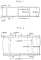
- a photographic film 1 has a width the same as commercially available photographic film, namely 35mm, but is not provided with perforations.
- a frame 3 in the film 1 defines an effective photographic area whose effective width W1 in the film-width direction is selected to be 30mm, and whose effective length L in the lengthwise or film-transporting direction of the film 1 is selected to be 40mm.
- a pitch L1 of the frame 3, which is the transport pitch of the film 1, is selected to be 42mm.
- the film 1 having the above-mentioned film format is accommodated in a film cassette 5, as shown in Figures 3 and 4.
- the width W1 of the frame 3 of the film 1 is 1.25 times as large as that (24mm) of the frame of existing photographic film.
- the image quality of the frame 3 in the film-width direction is therefore increased by 25% over existing film.
- the area of the frame 3 would be 1.56 (1.25 x 1.25) times the area of a frame of existing film.
- the available image quality could be improved by about 56%.
- the overall width W of the film 1 is selected to be the same as that of the existing 35mm wide photographic film so that facilities such as existing photographic film manufacturing apparatus, and apparatus for developing photographic film, can be utilized without any modifications or changes being required.
- facilities such as existing photographic film manufacturing apparatus, and apparatus for developing photographic film, can be utilized without any modifications or changes being required.
- apparatus for slitting wide photo-sensitive film on which photo-sensitive material has been coated, to form photographic film 35mm wide; apparatus for manufacturing a standard 35mm film cassette; and apparatus for winding the film into the cassette can be utilized without modification.
- the existing apparatus for developing, printing and enlarging can be used.
- band-shaped non-photographic areas 2A and 2B each having a width of 2.5mm are respectively provided between the edges of the frames 3 and the edges of the film 1, and these areas 2A and 2B make it possible to maintain the flatness of the film 1, to control the film 1, and to read and write data.
- the camera needs no sprockets to transport the film, and can as a result be made compact in size and light in weight.
- Figure 2 shows another photographic film 1, in which the width W is again 35mm, and a plurality of small apertures 4 are formed through the film 1 along the non-photographic area 2A.
- the apertures 4 are used to detect the transport distance of the film 1 as it is advanced.
- the format is similar to that of the film 1 of Figure 1, namely, the frame 3 has an effective photographic area that is 30mm in width W1 and 40mm in length L.
- the apertures 4 may each have a diameter of 1mm, and be aligned at approximately 1.25mm from one edge of the film 1, namely on the central line between an edge of the film 1 and the adjacent edge of the frame 3, at a predetermined pitch of, for example, 5.25mm.
- the apertures 4 may also be arranged in the other non-photographic area 2B.
- apertures 4 are used, when the film 1 is transported in a camera body, to form the frames 3 at a predetermined pitch of, for example, 42mm. More specifically, when the counted number of the apertures 4 reaches a predetermined value, the transport of the film 1 is stopped.
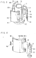
- a light-tight chamber 12 is located at a central portion of a camera body 11, and a lens system 13 is mounted at the front opening portion of the chamber 12.
- a film cassette accommodating space 14 is formed at one side portion of the camera body 11, for example, on the left-hand side in Figures 3 and 4, and a spool shaft 15 is aligned with the centre of the space 14.
- a cassette 5 containing the above-described photographic film 1 is set in the space 14, so as to engage with the spool shaft 15.
- a film take-up shaft 16 is mounted on the other side of the camera body 11, for example, on the right-hand side in Figures 3 and 4.
- the shaft 16 is driven to wind the film 1, preferably by a motor (not shown).
- the peripheral surface of the take-up shaft 16 is coated with a high friction material 17 such as neoprene, and, for example, three film guides 18A to 18C are arranged around the shaft 16.
- a high friction material 17 such as neoprene
- Each of the guides 18A to 18C provides a linear surface parallel to the central axis of the shaft 16 and provides an arcuate surface in the direction perpendicular to the central axis of the shaft 16.
- one end portion 181 of each of the film guides 18A to 18C is pivotably supported on the camera body 11, and the other end thereof is spring-biased towards the shaft 16 by a torsion spring 182 located at the pivoted end.
- Film guide rollers 10A to 10C are rotatably supported in the film guides 18A to 18C at the respective end portions adjacent to the shaft 16, so that they are arranged parallel to the central axis of the shaft 16.
- the structure of the film guides 18A, 18B and 18C is shown in more detail in Figure 6, in which the roller 10A of the film guide 18A has a predetermined diameter, and a permanent magnet 31 is secured to one end, for example, the top of the roller 10A.
- the magnet 31 is magnetized with N and S poles in its radial direction, and the film guide 18A has a magnetic sensor 32, for example, a Hall element, mounted at a position opposing the magnet 31.
- the aperture 19 has a length of 30mm (in the width-wise direction of the film 1) to define the frame 3 on the film 1.
- the aperture 19 does not come into close contact with the film 1, and the light arriving through the lens system 13 incident on the film 1 is not collimated, so that while the size of the frame 3 is 30mm x 40mm, the size of the aperture 9 is slightly smaller than 30 x 40mm.
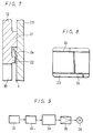
- two pairs of film guide rails 21 and 22 are respectively formed on the rearwardly facing, inner surface of the chamber 12 along, and at least over the portions corresponding to the top and bottom edges of the aperture 19.
- the rails 21 are located apart from each other by an inside distance substantially equal to 35mm, so as to define the position of the film 1 in its widthwise direction relative to the aperture 19.
- the rails 21 are formed parallel with each other and are also made thicker than the inside rails 22 by an amount at least equal to the thickness of the film 1.
- the rails 22 are respectively formed near the upper and lower edge portions of the aperture 19 and parallel therewith.
- a film pressure plate 23 in Figure 8 is attached to the inner or front surface of the rear cover (not shown) of the camera body 11 by some suitable means, such as a pressure spring, for example.
- a pair of rails 24, each having a predetermined height, are respectively mounted on the front surface of the pressure plate 23 at positions corresponding to the locations between the film guide rails 21 and 22 and parallel to the rails 21.
- the location of the film 1 is defined by the rails 22 in a widthwise direction, and the rails 24 contact the upper and lower edge portions of the film 1 in the forward direction or left-hand direction of Figure 7, so that the remaining portion of the film 1, that is, the area of the frame 3, is brought into close contact with the pressure plate 23.
- the rails 24 are not essential in order to provide flat contact between the film 1 and the pressure plate 23.
- the film area corresponding to the frame 3 can be given the necessary flatness by the pressure plate 23.
- a viewfinder, exposure control, shutter, and the like of the camera can be formed similarly to those of existing photographic cameras.
- the present camera may however be provided with a film transport amount detecting circuit as shown, for example, in Figures 9 and 10.
- the cassette 5 When the photographer prepares to take a picture, the cassette 5 is set in the space 14 and the film 1 is withdrawn from the cassette 5 across the aperture 19 to the take-up shaft 16, so that by means of the film guides 18A to 18C and the film guide rollers 10A to 10C, when the shaft 16 is rotated, the film 1 is wound around the shaft 16.
- the film 1 can be transported without requiring film transporting perforations.
- the rollers 10A to 10C and the magnet 31 are rotated in accordance with the movement of the film 1.
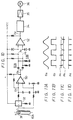
- the rotation of the magnet 31 is detected by the sensor 32, and the detected output is counted by a counter 33, the count from which is supplied to a system controller 34 (formed of a microcomputer), as shown in Figure 9.
- a system controller 34 formed of a microcomputer
- photographic data may be recorded in the non-photographic area between the edge of the photographic film and the frame, and data indicating the type of film may be previously recorded therein.
- the aperture 4 may be replaced with a magnetic mark or the like and the magnetic sensor 32 may be mounted on the rear cover or on the pressure plate.
- the system controller 34 is used to control the operation of the entire camera, for example, to determine the aperture and shutter speed.
- the roller 10A of the film guide 18A is rotated one revolution per predetermined transport amount of the film 1, the amount of the film 1 being transported is detected on the basis of the count of the counter 33. Then, the rotation of a drive motor 36, which drives the take-up shaft 16, is controlled through a motor drive amplifier 35, so that the transport corresponds to the count value, to determine the size of the frame 3.
- the film transport pitch is selected to be equal to an integral multiple of the minimum detectable value of film transport.
- the magnet 31 is formed as a dipole doughnut shape.
- the Hall element or magnetic sensor 32 senses the magnet 31 and generates a detected voltage Ea that changes in amplitude in response to revolutions of the magnet 31, as shown in Figure 11A.
- the voltage Ea is supplied to a voltage comparing circuit 50, wherein it is waveform-shaped to a square wave voltage Eb, having a period corresponding to the revolutions of the magnet 31, as represented by the waveform Eb in Figure 11B.
- the voltage Eb is supplied to differentiating circuits 51A and 51B that generate differentiated pulses Pa and Pb which correspond respectively to the trailing and leading edges of the voltage waveform Eb, and are shown in Figure 11C.
- the pulses Pa and Pb are supplied to a voltage comparing circuit 52 that generates one pulse Pd at every half period of the voltage Ea, or at every one-half revolution of the magnet 31, and the pulse Pd are shown in Figure 11D.
- This pulse signal Pd is supplied to the system controller 34.
- the system controller 34 controls the operation of the entire camera, as earlier noted. Each time the roller 10A of the film guide 18A rotates by one-half turn, the film 1 is transported a length equal to 5.25mm. Thus, the system controller 34 controls the drive motor 36, so that the number of the pulses Pd equals the count value corresponding to the size of the frame 3. For example, if the pitch is 42mm, the film 1 is transported until eight pulses Pd are obtained and the film 1 is therefore transported at the pitch of one frame 3 corresponding to the above-described format.
- the film guidance structure and the film transport detecting circuit even if the perforations used to transport the photographic film 1 are not present, the film can be transported at the correct frame pitch. Furthermore, the magnet 31 for detecting the transport amount of the film 1 is a dipole magnet, which is cheap.
- the leading and trailing edges of the resultant voltage Eb are both counted to detect the amount of the film 1 transported.
- the revolution provided when the detection roller 10A detects the amount of film 1 that is transported can be one-half revolution.
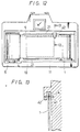
- Figure 12 is a rear view of the camera with the film 1 loaded and the rear cover removed.
- Figure 13 is an enlarged, cross-sectional view on line 13-13 in Figure 12.
- the film 1 having the format with the plurality of small apertures 4 as shown in Figure 2.
- a light emitting diode (LED) 41 of the photo-interrupter kind, and a photo-transistor 42 are mounted on the camera body 11 at a position downstream of the film 1 at a location corresponding to the upper edge portion of the aperture 19, so that the LED 41 and the photo-transistor 42 sandwich the apertures 4.
- the light emission wavelength of the LED 41 and the sensitivity peak of the photo-transistor 42 are selected to be in the infra-red ray wavelength range, for example, 940 nanometres.
- photographic film has a low transmissivity for infra-red rays, as compared with visible light, a level difference between the output from the photo-transistor 42 at an aperture 4 and other portions is enhanced, thereby making it possible positively to detect an aperture 4. Further, the LED 41 emits only infra-red light rays, thereby preventing the film 1 from being fogged.
- the infra-red light rays emitted from the LED 41 and received at the photo-transistor 42 are interrupted in accordance with the movement of the apertures 4, whereby the photo-transistor 42 generates a detection pulse that indicates the movement of each aperture 4.
- the photo-transistor 42 By supplying this pulse to the counter 33 in the detecting circuit of Figure 9, it is possible to control the transport amount of the film 1 as described above.
- Figure 14 shows another example of the film pressure plate 23 attached to the inner surface of the rear cover of the camera body, in which the film pressure plate 23 is attached to the front or inner surface of the rear cover 41 at a location opposing the aperture 19 of Figure 12 in the camera body 11.
- the pressure plate 23 is larger than the aperture 19, is quadrilateral or rectangular in shape, and does not include the rails that were shown in Figure 8.
- the pressure plate 23 has formed therein a through-hole 43 at a location corresponding to the corner of a frame of the film 1.
- six light-emitting element groups 44 Arranged behind the through-hole 43 are six light-emitting element groups 44. As shown in Figures 15A and 15B, these six groups 44 are aligned on a support plate 44A in the lengthwise direction of the film 1.
- each of these six groups 44 has a squarish B-letter resulting from a seven segment configuration.
- the light-emitting element groups 44 are pivotally mounted at the centre of a change-over lever 45 by a pin 44B, and one end of the lever 45 is pivotally mounted on a rear cover 141 by a pin 46.
- Each of the light-emitting groups 44 is electrically connected through cables 48 and contacts 49 to the system controller 34.
- the arcuate film guide 18A and the film guide roller 10A are mounted in the rear cover 141.
- a leaf spring 151 urges the film cassette (not shown) into place in the camera body 11.
- Figures 17A to 17G show respective examples of data that can be projected on the film 1 by the six light-emitting element groups 44.
- Figure 17A illustrates date data (December 24, 1988); Figure 17B illustrates time and date data (10:05, 24th); and Figure 17C illustrates time data (10:05.34).
- Figures 17D and 17E illustrate photographic data, for example, aperture 5.6 and shutter speed 1/500 second, and aperture 1.4 and shutter speed long (L), for example, twelve seconds.
- Figures 17F and 17G illustrate optional data, for example, in which a lens is a zoom lens of 70 to 135mm, and a lens is an f3.5 telephoto lens of 105mm, respectively.
- Figure 17H illustrates the font of numerals and characters which can be used as data 53 or 53'. These numerals and characters can be selectively projected inside or outside the frame 3, because the light-emitting element groups 44 are movable by means of the assembly shown in Figures 15A and 15B.
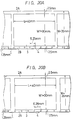
- Figures 18A to 18D are diagrams of a photographic format of a film 1 in which the minimum detection value of the film transport amount is selected to be 5.25mm
- Figures 19A to 19D are diagrams of a photographic format of a film 1 in which the minimum detection value of the film transport amount is selected to be 6.28mm.
- the width W of the film 1 is 35mm, which is equal to the width of existing photographic film, and the film 1 is not provided with perforations.
- a frame 3 defines an effective photographic area (see Figure 1A) whose effective width W1 in the film width direction is 30mm, and whose effective length L in the lengthwise direction of the film 1 is 40mm.
- a pitch L1 of the frame 3, which is the transport pitch of the film 1, is selected to be 42.0mm.
- the size and pitch of the frame 3 are selected in accordance with the aspect ratio 3:4 of existing television broadcasting systems.
- the effective width W1 of the effective photographic area or frame 3 is selected to be 30mm, the effective length L is selected to be 53.3mm, and the pitch L1 of the frame 3 is selected to be 57.75mm.
- These values are selected so as to conform to the standards of a high definition television (HDTV) system (Hi-Vision system).
- HDTV high definition television
- Hi-Vision system Hi-Vision system
- the aspect ratio of the frame 3 is 9:16.
- Figures 18A and 18B are present when the photographer takes a full-sized picture.
- a half-sized picture is taken, the size of the frame 3 is changed to 30mm x 22.5mm, and the transport pitch of the film 1 is changed to 26.5mm for the existing television broadcasting system as shown in Figure 18C, while the size of the frame 3 is changed to 30mm x 16.9mm, and the transport pitch of the film 1 is changed to 21.0mm for the HDTV system as shown in Figure 18D.
- the length of the longer side of the frame 3 is approximately 36mm, which provides an image quality substantially equal to that of the fill-sized picture of existing film.
- the film transport amount (transport pitch) in the photographic formats of the film 1 in Figures 18A to 18D is selected to be equal to an integral multiple of the minimum detectable value of film transport, that is 5.25mm.
- the diameter of the detection roller 10A for detecting the film transport amount is 3.34mm as described above.
- FIGS 19A to 19D Other examples of the transport pitches of the frame 3 shown in Figures 18A to 18D are represented in Figures 19A to 19D, respectively.
- the film transport amounts are each selected to be equal to an integral multiple of the minimum detectable value of film transport, that is, 6.28mm.
- Figures 20A and 20B are further examples of a photographic film 1, in which a plurality of small apertures 4 are formed through the film 1 along the lower non-photographic area 2B. These apertures 4 are used to detect the transport amount of the film 1 shown in Figure 18.
- the apertures 4 each have a diameter of 1mm, and are aligned from one edge of the film 1 by approximately 1.25mm, namely, on the central line between the edge of the film 1 and the edge of the frame 3 at a predetermined pitch, for example, 5.25mm as shown in Figure 20A.
- the apertures 4 are aligned at a pitch of 6.28mm as shown in Figure 20B.
- the pitch of the apertures 4 is selected to be 5.25mm or 6.28mm on the basis of the above-mentioned background
- the format of the film 1 can be suitably applied to an existing television broadcasting system and to the HDTV system, but also it can be applied to both of the full-sized picture and the half-sized picture.
- the number of apertures 4 is counted by the photo-interrupter utilizing infra-red rays.
- the transport of the film 1 is stopped, so that the frames 3 are automatically formed on the film 1 at a correct pitch.
- the apertures 4 are aligned on the lower non-photographic area 2B, whereas the apertures 4 are aligned on the upper non-photographic area 2A in Figure 2.
- the reason for this is that the location of the aperture 4 is determined in response to the location of the photo-interrupter, and the means for recording information on the film 1.
- the photographic area exposed to light differs from that explained in connection with Figures 3 and 4. This can be achieved by properly matching the size of the rectangular aperture 19 and the lens system 13 ( Figures 3 and 4). Moreover, when the apertures 4 are aligned on the opposite side or lower side, they may be located in accordance with the location of the photo-interrupter.
- the photographic film 1 may be either a positive or a negative photographic film.
- photograph data may be recorded in the non-effective photographic area between the edge of the photographic film and the frame, and data indicating the type of the photographic film 1 may be previously recorded therein.
- only one small aperture 4 may be provided per frame, or the small aperture 4 may be replaced with a magnetic mark or the like, and the magnetic sensor and the photo-transistor may be mounted on the rear cover or on the pressure plate.
Abstract
Description
- This invention relates to photographic camera systems and to film cassettes.
- A photographic film now widely used is 35mm wide, and the photo-sensitive materials for forming such a photographic film are standardized by the International Organization of Standards (ISO). In such a film, the width between the outer edges of the film is 35mm, and a plurality of rectangular perforations are aligned along each edge of the film. The perforations are used to transport the film as it is exposed, and they may also be used during the development and printing processes. The dimension of each perforation in the widthwise direction of the film is 2.79mm and the dimension in the lengthwise direction of the film is 1.98mm. The distance between each perforation and the edge of the film is 2.01mm, and the distance between the opposing perforations in respective sides of the film is 25mm. The pitch of the perforations is 4.75mm.
- In such film, each frame, which is the effective photographic area, is rectangular in shape and is 24mm in the widthwise direction of the film. The pitch of the frames is 38mm, which is eight times the pitch of the perforations which is taken as a reference.
- In order to improve the image quality obtained from such film the following proposals have been made: (1) the photo-sensitive material should be improved to improve resolution; and (2) the width of the film should be increased to increase the frame size, so that resulting prints would require less enlargement and would appear sharper.
- In general, the particle size of the photo-sensitive material coated on the film determines the resolution and the sensitivity of the film, and these two parameters are inversely related. Hence, without the discovery of a new photo-sensitive material, it is difficult to improve the image quality according to proposal (1).
- Proposal (2) involves an increase in the width of the photographic film. Thus, the camera must necessarily also be increased in size and weight, which goes contrary to the recent trend that seeks to reduce the size and weight of cameras. Furthermore, all existing equipment for manufacturing and for developing film would have to be modified to correspond to the increased width.
- Two other proposals that have been made involve changes to the camera: (3) the size or portion of the image that is picked-up can be changed by changing the magnification of the lens attached to the camera body; and (4) the effective photographic area on the film cam be increased by recording magnification control data for the printing equipment in an area between the frames.
- Proposal (3) requires an expensive lens, such as a telephoto lens.
- Proposal (4) is disclosed in US patent specification US-A-4 780 735. Close-up photography is in effect achieved without requiring an expensive zoom lens by limiting the photographic area of the film. On printing this limited area, the magnification is increased so that an apparent close-up is effected whilst utilizing a standard lens. US-A-4 780 735 also discloses a technique in which a 17-bit code, namely, control information for the magnification, date information, and the like is recorded in the blank area between successive frames.
- One problem with this, however, is that if slide film is used, the area between the frames is covered when a slide support frame is attached to the frame after development. If the film used is a negative film, then the film has to be kept un-cut to avoid losing the data.
- According to one aspect of the invention there is provided a photographic file having no sprocket driving apertures thereon and data disposed thereon close to the edge portion of said film said data concerning the dimension of one of the predetermined flames which is to be exposed on the effective photographic area of said film.
- According to another aspect of the invention there is provided a photographic camera having a cartridge accommodating unit, a film accommodating unit, a means for winding up a fill, which has no sprocket driving apertures and can record optical information at a position near its edge portion, between said cartridge accommodating unit and said film accommodating unit, and an information recording means for recording information at a position near an edge portion of said film from the other side surface side opposing said one surface side of the film exposed by an exposing means, the photographic camera being characterized in that said winding-up means carries out the winding-up by detecting the winding-up amount of said film in a non-mechanical fashion, and said information recording means records optical information between a photographic area, in which data indicating a standard of said film is printed to form a magnetic information and exposed by said exposing means, and said edge portion, and near said edge portion with no apertures.
- According to a further aspect of the invention there is provided a film system camera comprising a cartridge accommodating unit, a film accommodating unit, a means for winding up a film having no sprocket driving apertures and an aperture indicating a frame position of a photographic area formed near a first edge portion between said cartridge accommodating unit and said film accommodating unit, a detecting means for detecting the aperture of said film in an optical fashion, an exposing means for exposing said photograph area of said film, and a photograph information recording means for recording photographic information at a position near a second edge portion with no apertures and opposing to the position near said first edge portion adjacent to a frame exposed by said exposing means, wherein said photograph information recording means carries out the recording from other side surface side opposing to one side surface side of said film exposed by said exposing means.
- According to a still further aspect of the invention there is provided a film system camera, comprising a cartridge accommodating unit, a film accommodating unit, a means for winding up a film, which has no sprocket driving apertures and magnetic information to indicate frame position information of the film formed in a non-effective photographic area formed between a photographic area of the frame and an edge portion, between said cartridge accommodating unit and said film accommodating unit, a detecting means for detecting position information based on the magnetic information formed on said film, an exposing means for exposing said photographic area of said film, a control means for controlling said winding means based on position information detected by said detecting means and controlling said exposing means to expose said photographic area of said frame, and an information recording means for recording information supplied from said control means at a position near an edge portion of said film or in the photographic area of said film.
- According to yet a further aspect of the invention there is provided a photograph film, in which there are no sprocket driving apertures, a constant interval of apertures provided in a non-photographic area between a photographic area of a film and a film edge portion indicates a position of a frame exposed in said photographic area and a length of said frame in a film winding direction, a length of said photographic area in a film width direction and the interval of said apertures are set such that an aspect ratio of said frame becomes 9:16, information indicating a standard of said film is recorded in advance, and a film edge portion side opposing to a film edge side having said apertures of said non-photographic area has no aperture so as to be capable of recording an information concerning said frame by a camera.
- The invention will now be described by way of example with reference to the accompanying drawings, throughout which like parts are referred to by like references, and in which:
- Figure 1 is a plan view of a portion of a 35mm wide photographic film;
- Figure 2 is a plan view of another 35mm wide photographic film;
- Figure 3 is a plan view in partial cross-section of an embodiment of camera according to the present invention;
- Figure 4 is a rear elevational view of the camera of Figure 3 with the rear cover removed;
- Figure 5 is a perspective view of a film transporting mechanism and detecting mechanism in the camera of Figure 3;
- Figure 6 is an exploded perspective view showing the detecting mechanism of Figure 5 in more detail;
- Figure 7 is an enlarged, cross-sectional view on line 7-7 in Figure 4 with film loaded in the camera;
- Figure 8 is a front elevational view of an example of a film pressure plate used in the camera of Figure 3;
- Figure 9 is a block diagram of an example of the film transporting system used in the camera of Figure 3;
- Figure 10 is a schematic diagram of an example of a film transport detecting circuit used in the film transporting system of Figure 9;
- Figures 11A to 11D are waveform diagrams of signals present in the operation of the film transport detecting circuit of Figure 10;
- Figure 12 is a rear elevational view of another example of film transport detecting mechanism;
- Figure 13 is an enlarged, cross-sectional view on line 13-13 in Figure 12;
- Figure 14 is a front elevational view of another example of film pressure plate;
- Figures 15A and 15B are elevational views of a data recording system;
- Figure 16 is a plan view of a portion of film in which photographic data are recorded;
- Figures 17A to 17G and 17H are, respectively, schematic diagrams showing examples of various recorded data, and numerals and characters used to record the data;
- Figures 18A to 18D are plan views of a portion of film in which the minimum detection value of a film transport amount is 5.25mm;
- Figures 19A to 19D are plan views of a portion of film in which the minimum detection value of the film transport amount is 6.28mm;
- Figure 20A is a plan view of a portion of a 35mm wide photographic film having perforations, in which the minimum detection value of the film transport amount is 5.25mm; and
- Figure 20B is a plan view of a portion of a 35mm photographic film having perforations, in which the minimum detection value of the film transport amount is 6.28mm.
-
- A known 35mm photographic film will first be considered, then it will be explained how to increase the effective photographic area of film in its widthwise direction by eliminating the perforations. The manner in which the flatness of the film is maintained by using the portions outside the effective photographic area thereof will be considered next. Then the problem of how to transport the film accurately by a predetermined pitch, even although the perforations are absent, will be discussed. Lastly, how to make effective use of the film outside the effective photographic area by the elimination of the perforations will be explained.
- In Figure 1, a
photographic film 1 has a width the same as commercially available photographic film, namely 35mm, but is not provided with perforations. Aframe 3 in thefilm 1 defines an effective photographic area whose effective width W1 in the film-width direction is selected to be 30mm, and whose effective length L in the lengthwise or film-transporting direction of thefilm 1 is selected to be 40mm. A pitch L1 of theframe 3, which is the transport pitch of thefilm 1, is selected to be 42mm. Thefilm 1 having the above-mentioned film format is accommodated in afilm cassette 5, as shown in Figures 3 and 4. - The width W1 of the
frame 3 of thefilm 1 is 1.25 times as large as that (24mm) of the frame of existing photographic film. The image quality of theframe 3 in the film-width direction is therefore increased by 25% over existing film. - If the length L of the
frame 3 were increased by the same ratio as the width W1, then the area of theframe 3 would be 1.56 (1.25 x 1.25) times the area of a frame of existing film. Thus, the available image quality could be improved by about 56%. - If the area of the
frame 3 of thefilm 1 were:frame 3 would be increased by about 39% compared with the area of a frame of existing film, and the available image quality could be increased by about 39% compared with existing film. - Thus, if an image of the same image quality as that of existing photographic film is to be produced, it becomes possible to provide a larger picture or, alternatively, it is possible to use less magnification to provide the same size picture, thereby resulting in a sharper picture.
- The overall width W of the
film 1 is selected to be the same as that of the existing 35mm wide photographic film so that facilities such as existing photographic film manufacturing apparatus, and apparatus for developing photographic film, can be utilized without any modifications or changes being required. For example, apparatus for slitting wide photo-sensitive film on which photo-sensitive material has been coated, to form photographic film 35mm wide; apparatus for manufacturing a standard 35mm film cassette; and apparatus for winding the film into the cassette can be utilized without modification. Moreover, the existing apparatus for developing, printing and enlarging can be used. - Since the width W1 of the
frame 3 is selected to be 30mm, band-shapednon-photographic areas frames 3 and the edges of thefilm 1, and theseareas film 1, to control thefilm 1, and to read and write data. Moreover, the camera needs no sprockets to transport the film, and can as a result be made compact in size and light in weight. - Figure 2 shows another
photographic film 1, in which the width W is again 35mm, and a plurality ofsmall apertures 4 are formed through thefilm 1 along thenon-photographic area 2A. Theapertures 4 are used to detect the transport distance of thefilm 1 as it is advanced. The format is similar to that of thefilm 1 of Figure 1, namely, theframe 3 has an effective photographic area that is 30mm in width W1 and 40mm in length L. Theapertures 4 may each have a diameter of 1mm, and be aligned at approximately 1.25mm from one edge of thefilm 1, namely on the central line between an edge of thefilm 1 and the adjacent edge of theframe 3, at a predetermined pitch of, for example, 5.25mm. Theapertures 4 may also be arranged in the othernon-photographic area 2B. As is described below only oneaperture 4 may be provided per frame or theaperture 4 may be replaced with a magnetic mark or the like. Theapertures 4 are used, when thefilm 1 is transported in a camera body, to form theframes 3 at a predetermined pitch of, for example, 42mm. More specifically, when the counted number of theapertures 4 reaches a predetermined value, the transport of thefilm 1 is stopped. - Referring to Figure 3, a light-
tight chamber 12 is located at a central portion of acamera body 11, and alens system 13 is mounted at the front opening portion of thechamber 12. A filmcassette accommodating space 14 is formed at one side portion of thecamera body 11, for example, on the left-hand side in Figures 3 and 4, and aspool shaft 15 is aligned with the centre of thespace 14. When the photographer loads the camera, acassette 5 containing the above-describedphotographic film 1 is set in thespace 14, so as to engage with thespool shaft 15. - A film take-up
shaft 16 is mounted on the other side of thecamera body 11, for example, on the right-hand side in Figures 3 and 4. Theshaft 16 is driven to wind thefilm 1, preferably by a motor (not shown). - As shown in Figure 5, the peripheral surface of the take-up
shaft 16 is coated with ahigh friction material 17 such as neoprene, and, for example, three film guides 18A to 18C are arranged around theshaft 16. Each of theguides 18A to 18C provides a linear surface parallel to the central axis of theshaft 16 and provides an arcuate surface in the direction perpendicular to the central axis of theshaft 16. As shown in Figure 6, oneend portion 181 of each of the film guides 18A to 18C is pivotably supported on thecamera body 11, and the other end thereof is spring-biased towards theshaft 16 by atorsion spring 182 located at the pivoted end.Film guide rollers 10A to 10C are rotatably supported in the film guides 18A to 18C at the respective end portions adjacent to theshaft 16, so that they are arranged parallel to the central axis of theshaft 16. - The structure of the film guides 18A, 18B and 18C is shown in more detail in Figure 6, in which the
roller 10A of thefilm guide 18A has a predetermined diameter, and apermanent magnet 31 is secured to one end, for example, the top of theroller 10A. Themagnet 31 is magnetized with N and S poles in its radial direction, and thefilm guide 18A has amagnetic sensor 32, for example, a Hall element, mounted at a position opposing themagnet 31. - Referring back to Figures 3 and 4, it will be seen tat through the rear portion of the
chamber 12 there is formed a quadrilateral orrectangular aperture 19. Theaperture 19 has a length of 30mm (in the width-wise direction of the film 1) to define theframe 3 on thefilm 1. As will be described, when the photographer takes a picture, theaperture 19 does not come into close contact with thefilm 1, and the light arriving through thelens system 13 incident on thefilm 1 is not collimated, so that while the size of theframe 3 is 30mm x 40mm, the size of the aperture 9 is slightly smaller than 30 x 40mm. - As shown in Figure 7, which is an enlarged, cross-sectional view on line 7-7 in Figure 4, two pairs of
film guide rails chamber 12 along, and at least over the portions corresponding to the top and bottom edges of theaperture 19. Therails 21 are located apart from each other by an inside distance substantially equal to 35mm, so as to define the position of thefilm 1 in its widthwise direction relative to theaperture 19. Therails 21 are formed parallel with each other and are also made thicker than the inside rails 22 by an amount at least equal to the thickness of thefilm 1. Therails 22 are respectively formed near the upper and lower edge portions of theaperture 19 and parallel therewith. - A
film pressure plate 23 in Figure 8 is attached to the inner or front surface of the rear cover (not shown) of thecamera body 11 by some suitable means, such as a pressure spring, for example. A pair ofrails 24, each having a predetermined height, are respectively mounted on the front surface of thepressure plate 23 at positions corresponding to the locations between thefilm guide rails rails 21. The location of thefilm 1 is defined by therails 22 in a widthwise direction, and therails 24 contact the upper and lower edge portions of thefilm 1 in the forward direction or left-hand direction of Figure 7, so that the remaining portion of thefilm 1, that is, the area of theframe 3, is brought into close contact with thepressure plate 23. Therails 24 are not essential in order to provide flat contact between thefilm 1 and thepressure plate 23. - Accordingly, even although the
frame 3 is 30mm long in a widthwise direction, and each of the areas between the edges of theframe 3 and the edges of thefilm 1 is only 2.5mm wide, the film area corresponding to theframe 3 can be given the necessary flatness by thepressure plate 23. - It should be understood that other elements, such as a viewfinder, exposure control, shutter, and the like of the camera can be formed similarly to those of existing photographic cameras. The present camera may however be provided with a film transport amount detecting circuit as shown, for example, in Figures 9 and 10.
- When the photographer prepares to take a picture, the
cassette 5 is set in thespace 14 and thefilm 1 is withdrawn from thecassette 5 across theaperture 19 to the take-upshaft 16, so that by means of the film guides 18A to 18C and thefilm guide rollers 10A to 10C, when theshaft 16 is rotated, thefilm 1 is wound around theshaft 16. Thus, thefilm 1 can be transported without requiring film transporting perforations. - When the
film 1 is transported, therollers 10A to 10C and themagnet 31 are rotated in accordance with the movement of thefilm 1. The rotation of themagnet 31 is detected by thesensor 32, and the detected output is counted by acounter 33, the count from which is supplied to a system controller 34 (formed of a microcomputer), as shown in Figure 9. As is described below, photographic data may be recorded in the non-photographic area between the edge of the photographic film and the frame, and data indicating the type of film may be previously recorded therein. Theaperture 4 may be replaced with a magnetic mark or the like and themagnetic sensor 32 may be mounted on the rear cover or on the pressure plate. Thesystem controller 34 is used to control the operation of the entire camera, for example, to determine the aperture and shutter speed. Because theroller 10A of thefilm guide 18A is rotated one revolution per predetermined transport amount of thefilm 1, the amount of thefilm 1 being transported is detected on the basis of the count of thecounter 33. Then, the rotation of adrive motor 36, which drives the take-upshaft 16, is controlled through amotor drive amplifier 35, so that the transport corresponds to the count value, to determine the size of theframe 3. - Figure 10 is an example of a detecting circuit that detects the transport amount of the
film 1. Assuming that the film transport pitch corresponding to theframe 3 is 42.0mm, then: - That is, the film transport pitch is selected to be equal to an integral multiple of the minimum detectable value of film transport. In other words, the diameter of the
roller 10A is determined so that the minimum detection value of the film transport is 5.25mm. Since: 5.25mm = π x 3.34mm/2 Thus, when the diameter of thedetection roller 10A is 3.34mm, the transport amount of thefilm 1 corresponds to one-half revolution of theroller 10A. As seen from Figure 6, themagnet 31 is formed as a dipole doughnut shape. - The Hall element or
magnetic sensor 32 senses themagnet 31 and generates a detected voltage Ea that changes in amplitude in response to revolutions of themagnet 31, as shown in Figure 11A. As shown in Figure 10, the voltage Ea is supplied to avoltage comparing circuit 50, wherein it is waveform-shaped to a square wave voltage Eb, having a period corresponding to the revolutions of themagnet 31, as represented by the waveform Eb in Figure 11B. The voltage Eb is supplied to differentiatingcircuits - The pulses Pa and Pb are supplied to a
voltage comparing circuit 52 that generates one pulse Pd at every half period of the voltage Ea, or at every one-half revolution of themagnet 31, and the pulse Pd are shown in Figure 11D. This pulse signal Pd is supplied to thesystem controller 34. - The
system controller 34 controls the operation of the entire camera, as earlier noted. Each time theroller 10A of thefilm guide 18A rotates by one-half turn, thefilm 1 is transported a length equal to 5.25mm. Thus, thesystem controller 34 controls thedrive motor 36, so that the number of the pulses Pd equals the count value corresponding to the size of theframe 3. For example, if the pitch is 42mm, thefilm 1 is transported until eight pulses Pd are obtained and thefilm 1 is therefore transported at the pitch of oneframe 3 corresponding to the above-described format. - In the camera with this structure of the film guidance structure and the film transport detecting circuit, even if the perforations used to transport the
photographic film 1 are not present, the film can be transported at the correct frame pitch. Furthermore, themagnet 31 for detecting the transport amount of thefilm 1 is a dipole magnet, which is cheap. - In the film transport detecting circuit of Figure 10, the leading and trailing edges of the resultant voltage Eb are both counted to detect the amount of the
film 1 transported. Thus, even when themagnet 31 is a dipole magnet, the revolution provided when thedetection roller 10A detects the amount offilm 1 that is transported can be one-half revolution. - When the diameter of the
detection roller 10A is small, slip between thefilm 1 and thedetection roller 10A becomes large, thus resulting in a lowering of detection accuracy. When the diameter of theroller 10A is large, however, theroller 10A needs a large torque to transport thefilm 1. Thus, unless the motor size is increased, the slip between thefilm 1 and theroller 10A also becomes large, whereby the detection accuracy is lowered in this case too. Nevertheless, we have found that if the diameter of theroller 10A is 3.34mm as described above, this problem does not occur, and the amount of thefilm 1 being transported can be correctly detected. - Another example of a detector for detecting the transport of the
film 1 will be described with reference to Figures 12 and 13. Figure 12 is a rear view of the camera with thefilm 1 loaded and the rear cover removed. Figure 13 is an enlarged, cross-sectional view on line 13-13 in Figure 12. In each of Figures 12 and 13, there is employed thefilm 1 having the format with the plurality ofsmall apertures 4 as shown in Figure 2. - Referring to Figures 12 and 13, a light emitting diode (LED) 41 of the photo-interrupter kind, and a photo-
transistor 42 are mounted on thecamera body 11 at a position downstream of thefilm 1 at a location corresponding to the upper edge portion of theaperture 19, so that theLED 41 and the photo-transistor 42 sandwich theapertures 4. The light emission wavelength of theLED 41 and the sensitivity peak of the photo-transistor 42 are selected to be in the infra-red ray wavelength range, for example, 940 nanometres. - In general, because photographic film has a low transmissivity for infra-red rays, as compared with visible light, a level difference between the output from the photo-
transistor 42 at anaperture 4 and other portions is enhanced, thereby making it possible positively to detect anaperture 4. Further, theLED 41 emits only infra-red light rays, thereby preventing thefilm 1 from being fogged. - Thus, when the
film 1 is transported, the infra-red light rays emitted from theLED 41 and received at the photo-transistor 42 are interrupted in accordance with the movement of theapertures 4, whereby the photo-transistor 42 generates a detection pulse that indicates the movement of eachaperture 4. By supplying this pulse to thecounter 33 in the detecting circuit of Figure 9, it is possible to control the transport amount of thefilm 1 as described above. - Figure 14 shows another example of the
film pressure plate 23 attached to the inner surface of the rear cover of the camera body, in which thefilm pressure plate 23 is attached to the front or inner surface of therear cover 41 at a location opposing theaperture 19 of Figure 12 in thecamera body 11. Thepressure plate 23 is larger than theaperture 19, is quadrilateral or rectangular in shape, and does not include the rails that were shown in Figure 8. Thepressure plate 23 has formed therein a through-hole 43 at a location corresponding to the corner of a frame of thefilm 1. Arranged behind the through-hole 43 are six light-emitting element groups 44. As shown in Figures 15A and 15B, these sixgroups 44 are aligned on asupport plate 44A in the lengthwise direction of thefilm 1. For example, each of these sixgroups 44 has a squarish B-letter resulting from a seven segment configuration. The light-emittingelement groups 44 are pivotally mounted at the centre of a change-overlever 45 by apin 44B, and one end of thelever 45 is pivotally mounted on arear cover 141 by apin 46. - Thus, when the free end of the
lever 45 is moved upward and downward around thepin 46 as shown in Figures 15B and 15A, respectively, the light-emittingelement groups 44 are moved in the widthwise direction of thefilm 1. Thesupport plate 44A and, hence, the light-emittingelement groups 44, are guided byguide rails 47 so as to move linearly in the widthwise direction of thefilm 1. Thesupport plate 44A and the light-emittingelement groups 44 can be stabilized by a torque spring (not shown) at the end positions shown in Figures 15A and 15B, respectively. - Each of the light-emitting
groups 44 is electrically connected throughcables 48 andcontacts 49 to thesystem controller 34. The arcuate film guide 18A and thefilm guide roller 10A are mounted in therear cover 141. Aleaf spring 151 urges the film cassette (not shown) into place in thecamera body 11. - When the photographer takes a picture, if the free end of the
lever 45 is lowered as shown in Figure 15A, then the light-emittingelement groups 44 are located at a position corresponding to the lower portion of thehole 43, so thatdata 53 is projected on the area of theframe 3 at a position just along the upper edge thereof, as shown in Figure 16. - If the free end of the
lever 45 is moved upward, as shown in Figure 15B, then the light-emittingelement groups 44 are located at a position corresponding to the upper portion of thehole 43, so that data 53' is recorded outside the effective area of theframe 3, at a position just along the upper edge thereof, as shown in Figure 16. - Figures 17A to 17G show respective examples of data that can be projected on the
film 1 by the six light-emitting element groups 44. - Figure 17A illustrates date data (December 24, 1988); Figure 17B illustrates time and date data (10:05, 24th); and Figure 17C illustrates time data (10:05.34). Figures 17D and 17E illustrate photographic data, for example, aperture 5.6 and
shutter speed 1/500 second, and aperture 1.4 and shutter speed long (L), for example, twelve seconds. Figures 17F and 17G illustrate optional data, for example, in which a lens is a zoom lens of 70 to 135mm, and a lens is an f3.5 telephoto lens of 105mm, respectively. - Figure 17H illustrates the font of numerals and characters which can be used as
data 53 or 53'. These numerals and characters can be selectively projected inside or outside theframe 3, because the light-emittingelement groups 44 are movable by means of the assembly shown in Figures 15A and 15B. - Figures 18A to 18D are diagrams of a photographic format of a
film 1 in which the minimum detection value of the film transport amount is selected to be 5.25mm, and Figures 19A to 19D are diagrams of a photographic format of afilm 1 in which the minimum detection value of the film transport amount is selected to be 6.28mm. Throughout Figures 18A to 19D, the width W of thefilm 1 is 35mm, which is equal to the width of existing photographic film, and thefilm 1 is not provided with perforations. - In the example shown in Figure 18A, a
frame 3 defines an effective photographic area (see Figure 1A) whose effective width W1 in the film width direction is 30mm, and whose effective length L in the lengthwise direction of thefilm 1 is 40mm. A pitch L1 of theframe 3, which is the transport pitch of thefilm 1, is selected to be 42.0mm. The size and pitch of theframe 3 are selected in accordance with the aspect ratio 3:4 of existing television broadcasting systems. - In the example shown in Figure 18B, the effective width W1 of the effective photographic area or
frame 3 is selected to be 30mm, the effective length L is selected to be 53.3mm, and the pitch L1 of theframe 3 is selected to be 57.75mm. These values are selected so as to conform to the standards of a high definition television (HDTV) system (Hi-Vision system). In this case, the aspect ratio of theframe 3 is 9:16. - The values in Figures 18A and 18B are present when the photographer takes a full-sized picture. When, on the other hand, a half-sized picture is taken, the size of the
frame 3 is changed to 30mm x 22.5mm, and the transport pitch of thefilm 1 is changed to 26.5mm for the existing television broadcasting system as shown in Figure 18C, while the size of theframe 3 is changed to 30mm x 16.9mm, and the transport pitch of thefilm 1 is changed to 21.0mm for the HDTV system as shown in Figure 18D. Thus, even when a half-sized picture is taken, the length of the longer side of theframe 3 is approximately 36mm, which provides an image quality substantially equal to that of the fill-sized picture of existing film. - Since the minimum detection value of the film transport amount is selected to be 5.25mm as earlier noted, the film transport amount (transport pitch) in the photographic formats of the
film 1 in Figures 18A to 18D is selected to be equal to an integral multiple of the minimum detectable value of film transport, that is 5.25mm. Thus, the film transport pitches in Figures 18A to 18D are calculated as:mm x 4 - The diameter of the
detection roller 10A for detecting the film transport amount is 3.34mm as described above. - Other examples of the transport pitches of the
frame 3 shown in Figures 18A to 18D are represented in Figures 19A to 19D, respectively. In Figures 19A to 19D, the film transport amounts (transport pitches) are each selected to be equal to an integral multiple of the minimum detectable value of film transport, that is, 6.28mm. Thus, the film transport pitches in Figures 19A to 19D are calculated as:detection roller 10A for detecting the film transport amount is determined as 4.0mm, and the minimum detection value of the film transport amount is 6.28mm, such that: - The above-mentioned respective values in Figures 19A and 19B correspond to existing television broadcasting systems and the HDTV system, when a photographer takes a full-sized picture, while the respective values in Figures 19C and 19D correspond similarly for a half-sized picture.
- Figures 20A and 20B are further examples of a
photographic film 1, in which a plurality ofsmall apertures 4 are formed through thefilm 1 along the lowernon-photographic area 2B. Theseapertures 4 are used to detect the transport amount of thefilm 1 shown in Figure 18. Theapertures 4 each have a diameter of 1mm, and are aligned from one edge of thefilm 1 by approximately 1.25mm, namely, on the central line between the edge of thefilm 1 and the edge of theframe 3 at a predetermined pitch, for example, 5.25mm as shown in Figure 20A. Similarly, for the format of thefilm 1 shown in Figure 19, theapertures 4 are aligned at a pitch of 6.28mm as shown in Figure 20B. - Since the pitch of the
apertures 4 is selected to be 5.25mm or 6.28mm on the basis of the above-mentioned background, the format of thefilm 1 can be suitably applied to an existing television broadcasting system and to the HDTV system, but also it can be applied to both of the full-sized picture and the half-sized picture. - More specifically, when the
film 1 is transported in thecamera body 11, the number ofapertures 4 is counted by the photo-interrupter utilizing infra-red rays. When the count reaches a predetermined value, the transport of thefilm 1 is stopped, so that theframes 3 are automatically formed on thefilm 1 at a correct pitch. - In the examples shown in Figures 20A and 20B, the
apertures 4 are aligned on the lowernon-photographic area 2B, whereas theapertures 4 are aligned on the uppernon-photographic area 2A in Figure 2. The reason for this is that the location of theaperture 4 is determined in response to the location of the photo-interrupter, and the means for recording information on thefilm 1. - Throughout Figures 18A to 18D, 19A to 19D and 20A to 20B, the photographic area exposed to light differs from that explained in connection with Figures 3 and 4. This can be achieved by properly matching the size of the
rectangular aperture 19 and the lens system 13 (Figures 3 and 4). Moreover, when theapertures 4 are aligned on the opposite side or lower side, they may be located in accordance with the location of the photo-interrupter. - The
photographic film 1 may be either a positive or a negative photographic film. - Moreover, photograph data may be recorded in the non-effective photographic area between the edge of the photographic film and the frame, and data indicating the type of the
photographic film 1 may be previously recorded therein. Also, only onesmall aperture 4 may be provided per frame, or thesmall aperture 4 may be replaced with a magnetic mark or the like, and the magnetic sensor and the photo-transistor may be mounted on the rear cover or on the pressure plate.
Claims (6)
- A photographic file having no sprocket driving apertures thereon and data disposed thereon close to the edge portion of said film said data concerning the dimension of one of the predetermined frames which is to be exposed on the effective photographic area of said film
- In a photographic camera having a cartridge accommodating unit, a film accommodating unit, a means for winding up a fil, which has no sprocket driving apertures and can record optical information at a position near its edge portion, between said cartridge accommodating unit and said film accommodating unit, and an information recording means for recording information at a position near an edge portion of said film from the other side surface side opposing said one surface side of the film exposed by an exposing means, the photographic camera being characterized in that said winding-up means carries out the winding-up by detecting the winding-up amount of said film in a non-mechanical fashion, and said information recording means records optical information between a photographic area, in which data indicating a standard of said film is printed to form a magnetic information and exposed by said exposing means, and said edge portion, and near said edge portion with no apertures.
- A film system camera comprising a cartridge accommodating unit, a film accommodating unit, a means for winding up a film having no sprocket driving apertures and an aperture indicating a frame position of a photographic area formed near a first edge portion between said cartridge accommodating unit and said film accommodating unit, a detecting means for detecting the aperture of said film in an optical fashion, an exposing means for exposing said photograph area of said film, and a photograph information recording means for recording photographic information at a position near a second edge portion with no apertures and opposing to the position near said first edge portion adjacent to a frame exposed by said exposing means, wherein said photograph information recording means carries out the recording from other side surface side opposing to one side surface side of said film exposed by said exposing means.
- A film system camera, comprising a cartridge accommodating unit, a film accommodating unit, a means for winding up a film, which has no sprocket driving apertures and magnetic information to indicate frame position information of the film formed in a non-effective photographic area formed between a photographic area of the frame and an edge portion, between said cartridge accommodating unit and said film accommodating unit, a detecting means for detecting position information based on the magnetic information formed on said film, an exposing means for exposing said photographic area of said film, a control means for controlling said winding means based on position information detected by said detecting means and controlling said exposing means to expose said photographic area of said frame, and an information recording means for recording information supplied from said control means at a position near an edge portion of said film or in the photographic area of said film.
- A film system camera, comprising a cartridge accommodating unit, a film accommodating unit, a means for winding up a film, which has no sprocket driving apertures, in which a constant interval of apertures formed in a non-photographic area between a photographic area of the film and an edge portion of the film indicates a position of a frame exposed in said photographic area and a length of said frame in a film winding direction, a length of said photographic area in a film width direction and the interval of said apertures are set such that an aspect ratio of said frame becomes 9:16, and information indicating a standard of said film is recorded, between said cartridge accommodating unit and said film accommodating unit, a detecting means for detecting said aperture, a control means for controlling said winding means based on a detected signal from said detecting means, an exposing means for exposing said photographic area positioned by said winding means such that the aspect ratio of a frame becomes 9:16, and a photographic information recording means for recording a photographic information of said frame on a non-photographic area with no apertures on a film edge side opposing to a film edge side having said aperture in said non-photographic area.
- A photograph film, in which there are no sprocket driving apertures, a constant interval of apertures provided in a non-photographic area between a photographic area of a film and a film edge portion indicates a position of a frame exposed in said photographic area and a length of said frame in a film winding direction, a length of said photographic area in a film width direction and the interval of said apertures are set such that an aspect ratio of said frame becomes 9:16, information indicating a standard of said film is recorded in advance, and a film edge portion side opposing to a film edge side having said apertures of said non-photographic area has no aperture so as to be capable of recording an information concerning said frame by a camera
Priority Applications (6)
| Application Number | Priority Date | Filing Date | Title |
|---|---|---|---|
| EP00111650A EP1033608B1 (en) | 1988-08-31 | 1989-08-25 | Photographic camera systems and film cassettes |
| EP00111649A EP1033607B1 (en) | 1988-08-31 | 1989-08-25 | Photographic camera systems and film cassettes |
| EP00111651A EP1033609B1 (en) | 1988-08-31 | 1989-08-25 | Photographic camera systems and film cassettes |
| EP00111652A EP1033610B1 (en) | 1988-08-31 | 1989-08-25 | Photographic camera systems and film cassettes |
| EP00111654A EP1033612B1 (en) | 1988-08-31 | 1989-08-25 | Photographic camera systems and film cassettes |
| EP00111653A EP1033611B1 (en) | 1988-08-31 | 1989-08-25 | Photographic camera systems and film cassettes |
Applications Claiming Priority (8)
| Application Number | Priority Date | Filing Date | Title |
|---|---|---|---|
| JP21782588 | 1988-08-31 | ||
| JP21782688A JP2751234B2 (en) | 1988-08-31 | 1988-08-31 | Film camera |
| JP21782688 | 1988-08-31 | ||
| JP63217825A JP2821599B2 (en) | 1988-08-31 | 1988-08-31 | Camera and film cartridge |
| JP21974088 | 1988-09-02 | ||
| JP21974088A JPH0267537A (en) | 1988-09-02 | 1988-09-02 | Film type camera |
| EP89308661A EP0357355B1 (en) | 1988-08-31 | 1989-08-25 | Photographic camera |
| EP94109284A EP0616244A3 (en) | 1988-08-31 | 1989-08-25 | Film cassettes. |
Related Parent Applications (3)
| Application Number | Title | Priority Date | Filing Date |
|---|---|---|---|
| EP89308661.1 Division | 1989-08-25 | ||
| EP94109284A Division EP0616244A3 (en) | 1988-08-31 | 1989-08-25 | Film cassettes. |
| EP94109284.3 Division | 1994-06-16 |
Related Child Applications (12)
| Application Number | Title | Priority Date | Filing Date |
|---|---|---|---|
| EP00111649A Division EP1033607B1 (en) | 1988-08-31 | 1989-08-25 | Photographic camera systems and film cassettes |
| EP00111650A Division EP1033608B1 (en) | 1988-08-31 | 1989-08-25 | Photographic camera systems and film cassettes |
| EP00111654A Division EP1033612B1 (en) | 1988-08-31 | 1989-08-25 | Photographic camera systems and film cassettes |
| EP00111653A Division EP1033611B1 (en) | 1988-08-31 | 1989-08-25 | Photographic camera systems and film cassettes |
| EP00111652A Division EP1033610B1 (en) | 1988-08-31 | 1989-08-25 | Photographic camera systems and film cassettes |
| EP00111651A Division EP1033609B1 (en) | 1988-08-31 | 1989-08-25 | Photographic camera systems and film cassettes |
| EP00111654.0 Division-Into | 2000-05-31 | ||
| EP00111650.8 Division-Into | 2000-05-31 | ||
| EP00111653.2 Division-Into | 2000-05-31 | ||
| EP00111649.0 Division-Into | 2000-05-31 | ||
| EP00111651.6 Division-Into | 2000-05-31 | ||
| EP00111652.4 Division-Into | 2000-05-31 |
Publications (3)
| Publication Number | Publication Date |
|---|---|
| EP0959382A2 true EP0959382A2 (en) | 1999-11-24 |
| EP0959382A3 EP0959382A3 (en) | 2001-05-02 |
| EP0959382B1 EP0959382B1 (en) | 2003-10-15 |
Family
ID=27330073
Family Applications (12)
| Application Number | Title | Priority Date | Filing Date |
|---|---|---|---|
| EP00111650A Expired - Lifetime EP1033608B1 (en) | 1988-08-31 | 1989-08-25 | Photographic camera systems and film cassettes |
| EP00111653A Expired - Lifetime EP1033611B1 (en) | 1988-08-31 | 1989-08-25 | Photographic camera systems and film cassettes |
| EP00111651A Expired - Lifetime EP1033609B1 (en) | 1988-08-31 | 1989-08-25 | Photographic camera systems and film cassettes |
| EP00111649A Expired - Lifetime EP1033607B1 (en) | 1988-08-31 | 1989-08-25 | Photographic camera systems and film cassettes |
| EP97203178A Expired - Lifetime EP0822442B1 (en) | 1988-08-31 | 1989-08-25 | Photographic camera systems and film cassettes |
| EP94109284A Ceased EP0616244A3 (en) | 1988-08-31 | 1989-08-25 | Film cassettes. |
| EP99115811A Expired - Lifetime EP0959382B1 (en) | 1988-08-31 | 1989-08-25 | Photographic camera systems and film cassettes |
| EP00111654A Expired - Lifetime EP1033612B1 (en) | 1988-08-31 | 1989-08-25 | Photographic camera systems and film cassettes |
| EP96110972A Expired - Lifetime EP0738914B1 (en) | 1988-08-31 | 1989-08-25 | Photographic camera systems and film cassettes |
| EP89308661A Expired - Lifetime EP0357355B1 (en) | 1988-08-31 | 1989-08-25 | Photographic camera |
| EP00111652A Expired - Lifetime EP1033610B1 (en) | 1988-08-31 | 1989-08-25 | Photographic camera systems and film cassettes |
| EP96116287A Expired - Lifetime EP0764873B1 (en) | 1988-08-31 | 1989-08-25 | Photographic camera systems and film cassettes |
Family Applications Before (6)
| Application Number | Title | Priority Date | Filing Date |
|---|---|---|---|
| EP00111650A Expired - Lifetime EP1033608B1 (en) | 1988-08-31 | 1989-08-25 | Photographic camera systems and film cassettes |
| EP00111653A Expired - Lifetime EP1033611B1 (en) | 1988-08-31 | 1989-08-25 | Photographic camera systems and film cassettes |
| EP00111651A Expired - Lifetime EP1033609B1 (en) | 1988-08-31 | 1989-08-25 | Photographic camera systems and film cassettes |
| EP00111649A Expired - Lifetime EP1033607B1 (en) | 1988-08-31 | 1989-08-25 | Photographic camera systems and film cassettes |
| EP97203178A Expired - Lifetime EP0822442B1 (en) | 1988-08-31 | 1989-08-25 | Photographic camera systems and film cassettes |
| EP94109284A Ceased EP0616244A3 (en) | 1988-08-31 | 1989-08-25 | Film cassettes. |
Family Applications After (5)
| Application Number | Title | Priority Date | Filing Date |
|---|---|---|---|
| EP00111654A Expired - Lifetime EP1033612B1 (en) | 1988-08-31 | 1989-08-25 | Photographic camera systems and film cassettes |
| EP96110972A Expired - Lifetime EP0738914B1 (en) | 1988-08-31 | 1989-08-25 | Photographic camera systems and film cassettes |
| EP89308661A Expired - Lifetime EP0357355B1 (en) | 1988-08-31 | 1989-08-25 | Photographic camera |
| EP00111652A Expired - Lifetime EP1033610B1 (en) | 1988-08-31 | 1989-08-25 | Photographic camera systems and film cassettes |
| EP96116287A Expired - Lifetime EP0764873B1 (en) | 1988-08-31 | 1989-08-25 | Photographic camera systems and film cassettes |
Country Status (3)
| Country | Link |
|---|---|
| US (1) | US5049908A (en) |
| EP (12) | EP1033608B1 (en) |
| DE (11) | DE68929492T2 (en) |
Families Citing this family (40)
| Publication number | Priority date | Publication date | Assignee | Title |
|---|---|---|---|---|
| US5255031A (en) * | 1989-11-13 | 1993-10-19 | Fuji Photo Film Co., Ltd. | Data-retainable photographic film cartridge |
| JP2548694Y2 (en) * | 1989-11-13 | 1997-09-24 | 富士写真フイルム株式会社 | Photographic film cartridge that can record information |
| EP0503510B1 (en) * | 1991-03-08 | 1997-06-04 | Fuji Photo Film Co., Ltd. | Photographic film package |
| US5389983A (en) * | 1991-08-15 | 1995-02-14 | Olympus Optical Co., Ltd. | Camera |
| JPH05100356A (en) * | 1991-10-09 | 1993-04-23 | Fuji Photo Film Co Ltd | Photographic film |
| DE69333158T2 (en) * | 1992-03-17 | 2004-08-12 | Sony Corp. | Photographic film printer |
| US5600386A (en) * | 1992-03-17 | 1997-02-04 | Sony Corporation | Photographic camera system |
| US6470152B2 (en) | 1992-03-17 | 2002-10-22 | Sony Corporation | Photographic and video image system |
| US6006042A (en) * | 1992-03-17 | 1999-12-21 | Sony Corporation | Photographic camera system |
| US5570147A (en) | 1992-03-17 | 1996-10-29 | Sony Corporation | Photographic camera system |
| USRE36753E (en) * | 1992-03-17 | 2000-06-27 | Sony Corporation | Photographic camera system |
| US6600880B2 (en) | 1992-03-17 | 2003-07-29 | Sony Corporation | Photographic camera system |
| US6115558A (en) * | 1992-03-17 | 2000-09-05 | Sony Corporation | Photographic camera system |
| USRE36877E (en) * | 1992-03-17 | 2000-09-19 | Sony Corporation | Photographic camera system |
| US6151456A (en) * | 1993-03-04 | 2000-11-21 | Sony Corporation | Photographic camera system |
| US5752114A (en) * | 1992-03-17 | 1998-05-12 | Sony Corporation | Photographic and video image system |
| US6583851B2 (en) | 1992-03-17 | 2003-06-24 | Sony Corporation | Photographic and video image system |
| US5652643A (en) | 1992-03-17 | 1997-07-29 | Sony Corporation | Photographic and video image system |
| JP3315159B2 (en) * | 1992-09-14 | 2002-08-19 | オリンパス光学工業株式会社 | Camera that can record data |
| EP0598245A1 (en) * | 1992-11-19 | 1994-05-25 | Eastman Kodak Company | Camera film metering sensor apparatus |
| JPH06250280A (en) * | 1993-02-26 | 1994-09-09 | Canon Inc | Camera |
| US5345286A (en) * | 1993-05-11 | 1994-09-06 | Eastman Kodak Company | Method and apparatus for controlling film drive |
| JPH07273129A (en) * | 1993-06-15 | 1995-10-20 | Toshiba Corp | Schottky gate type field effect transistor and its fabrication |
| JPH0713265A (en) * | 1993-06-21 | 1995-01-17 | Sony Corp | Recorded and projector for motion picture film |
| JPH07319015A (en) * | 1994-05-24 | 1995-12-08 | Fuji Photo Film Co Ltd | Camera |
| US5541690A (en) * | 1994-11-28 | 1996-07-30 | Eastman Kodak Company | Half-frame film metering |
| JPH08236806A (en) * | 1995-02-27 | 1996-09-13 | Minolta Co Ltd | Mounting structure of photo-interrupter |
| DE69725914T2 (en) * | 1996-03-11 | 2004-11-04 | Fuji Photo Film Co., Ltd., Minami-Ashigara | Image generation process and system |
| US5745797A (en) * | 1997-04-21 | 1998-04-28 | Eastman Kodak Company | Camera assembly using mandrel to roll film in chamber |
| US5937208A (en) * | 1997-05-08 | 1999-08-10 | Eastman Kodak Company | Film scrolling method, apparatus and camera |
| US5805935A (en) * | 1997-05-30 | 1998-09-08 | Eastman Kodak Company | Two roller film scroller and method |
| US5797045A (en) * | 1997-05-30 | 1998-08-18 | Eastman Kodak Company | Three roller film winder and method |
| US5926654A (en) * | 1998-02-27 | 1999-07-20 | Eastman Kodak Company | Camera frame assembly having a baffled supply chamber and film loading apparatus and method |
| US5999744A (en) * | 1998-06-12 | 1999-12-07 | Eastman Kodak Company | Rotating hook film loader and method |
| US6094533A (en) * | 1998-06-12 | 2000-07-25 | Eastman Kodak Company | Film edge driving film loader, film loading method and camera frame assembly |
| US5978596A (en) * | 1998-07-07 | 1999-11-02 | Eastman Kodak Company | One-time-use camera bends wider film leader widthwise to conserve space |
| EP1670233A1 (en) | 1999-12-28 | 2006-06-14 | Sony Corporation | A photographic image commercial transaction system using a portable music player |
| DE60044179D1 (en) | 1999-12-28 | 2010-05-27 | Sony Corp | System and method for the commercial traffic of images |
| US7092284B2 (en) * | 2004-08-20 | 2006-08-15 | Infineon Technologies Ag | MRAM with magnetic via for storage of information and field sensor |
| DE102009050084A1 (en) | 2009-10-20 | 2011-07-28 | Fasel, Albert, 65520 | Multilayer hose with a tubular inner film, apparatus and method for its production and its use |
Citations (9)
| Publication number | Priority date | Publication date | Assignee | Title |
|---|---|---|---|---|
| US3678834A (en) * | 1971-06-04 | 1972-07-25 | Dominic S Melino | Reversible film camera with selectable exposure sizes |
| US3753249A (en) * | 1967-01-30 | 1973-08-14 | D Silverman | Information systems using arrays of multiple spot patterns |
| US4146321A (en) * | 1977-08-08 | 1979-03-27 | Melillo Dominic S | Reversible film cartridge and camera |
| GB2084746A (en) * | 1980-08-25 | 1982-04-15 | Nippon Kogaku Kk | Detecting coded information on film |
| US4396164A (en) * | 1980-04-11 | 1983-08-02 | Minolta Camera Kabushiki Kaisha | Easy loading mechanism for cameras |
| US4401376A (en) * | 1982-03-15 | 1983-08-30 | Laszlo Pomazi | Film design and improved circuit therefor enabling utilization of greater film exposure area |
| US4609812A (en) * | 1981-02-27 | 1986-09-02 | Drexler Technology Corporation | Prerecorded dual strip data storage card |
| US4701046A (en) * | 1984-12-19 | 1987-10-20 | Koji Shiga | Method of photographing on microfilm and apparatus therefor |
| US4705372A (en) * | 1986-10-10 | 1987-11-10 | The Laitram Corporation | Camera for recording keyboard entry of data on film edge |
Family Cites Families (18)
| Publication number | Priority date | Publication date | Assignee | Title |
|---|---|---|---|---|
| US1572252A (en) * | 1920-05-03 | 1926-02-09 | Eastman Kodak Co | Motion-picture apparatus |
| US3867030A (en) * | 1970-06-09 | 1975-02-18 | Atsuyuki Tanaka | Film control system by picture frame edge signals of a film |
| US3843956A (en) * | 1973-09-25 | 1974-10-22 | J Kauneckas | Data recording system for photographic cameras |
| US3865738A (en) * | 1974-01-21 | 1975-02-11 | Miklos Lente | Method of making motion pictures |
| JPS5945971B2 (en) * | 1975-08-20 | 1984-11-09 | キヤノン株式会社 | data imprint device |
| JPS542115A (en) * | 1977-06-07 | 1979-01-09 | Fuji Photo Film Co Ltd | Data imprinting device for cameras |
| FR2452129B1 (en) * | 1979-03-20 | 1985-10-25 | Aaton Sa | DEVICE FOR TAKING PICTURES FOR RECORDING IMAGES ON A MOBILE MEDIUM |
| JPS55134827A (en) * | 1979-04-06 | 1980-10-21 | Olympus Optical Co Ltd | Photographed frame number detector of film |
| DE3039738A1 (en) * | 1980-10-22 | 1982-04-29 | Kielcolor Photo Labor GmbH & Co KG, 2300 Kiel | Data indexing strip for negative film - has magnetic strip attached along one side of processed film with printing details |
| US4431292A (en) * | 1980-11-18 | 1984-02-14 | Ricoh Company, Ltd. | Film feeding circuit |
| JPS58145931A (en) * | 1982-02-25 | 1983-08-31 | Konishiroku Photo Ind Co Ltd | Device for confirming film feed |
| US4490027A (en) * | 1983-01-17 | 1984-12-25 | Eastman Kodak Company | Magnetically encoded film containers and camera adjusting mechanisms responsive thereto |
| JPS60166939A (en) * | 1984-02-09 | 1985-08-30 | Canon Inc | Data imprinting camera |
| US4659213A (en) * | 1985-04-08 | 1987-04-21 | Fuji Photo Film Co., Ltd. | Method and apparatus for detecting and processing image information |
| US4693591A (en) * | 1985-08-05 | 1987-09-15 | Minolta Camera Kabushiki Kaisha | Microfilm and microfilm printer |
| US4780735A (en) | 1985-08-29 | 1988-10-25 | Minolta Camera Kabushiki Kaisha | Photographic camera |
| US4736215A (en) * | 1986-11-21 | 1988-04-05 | Polaroid Corporation | Photographic method and apparatus employing automatic camera adjustment |
| US4860037A (en) * | 1988-09-12 | 1989-08-22 | Eastman Kodak Company | Film cassette with magnetic film leader |
-
1989
- 1989-08-25 EP EP00111650A patent/EP1033608B1/en not_active Expired - Lifetime
- 1989-08-25 EP EP00111653A patent/EP1033611B1/en not_active Expired - Lifetime
- 1989-08-25 EP EP00111651A patent/EP1033609B1/en not_active Expired - Lifetime
- 1989-08-25 DE DE68929492T patent/DE68929492T2/en not_active Expired - Fee Related
- 1989-08-25 DE DE68929490T patent/DE68929490T2/en not_active Expired - Fee Related
- 1989-08-25 DE DE68929495T patent/DE68929495T2/en not_active Expired - Fee Related
- 1989-08-25 DE DE68929452T patent/DE68929452T2/en not_active Expired - Fee Related
- 1989-08-25 EP EP00111649A patent/EP1033607B1/en not_active Expired - Lifetime
- 1989-08-25 EP EP97203178A patent/EP0822442B1/en not_active Expired - Lifetime
- 1989-08-25 EP EP94109284A patent/EP0616244A3/en not_active Ceased
- 1989-08-25 EP EP99115811A patent/EP0959382B1/en not_active Expired - Lifetime
- 1989-08-25 EP EP00111654A patent/EP1033612B1/en not_active Expired - Lifetime
- 1989-08-25 EP EP96110972A patent/EP0738914B1/en not_active Expired - Lifetime
- 1989-08-25 DE DE68927763T patent/DE68927763T2/en not_active Expired - Fee Related
- 1989-08-25 EP EP89308661A patent/EP0357355B1/en not_active Expired - Lifetime
- 1989-08-25 DE DE68929497T patent/DE68929497T2/en not_active Expired - Fee Related
- 1989-08-25 EP EP00111652A patent/EP1033610B1/en not_active Expired - Lifetime
- 1989-08-25 DE DE68929491T patent/DE68929491T2/en not_active Expired - Fee Related
- 1989-08-25 DE DE68929496T patent/DE68929496T2/en not_active Expired - Fee Related
- 1989-08-25 EP EP96116287A patent/EP0764873B1/en not_active Expired - Lifetime
- 1989-08-25 DE DE68929450T patent/DE68929450T2/en not_active Expired - Fee Related
- 1989-08-25 DE DE68929470T patent/DE68929470T2/en not_active Expired - Fee Related
- 1989-08-25 DE DE68929494T patent/DE68929494T2/en not_active Expired - Fee Related
- 1989-08-28 US US07/399,028 patent/US5049908A/en not_active Expired - Lifetime
Patent Citations (9)
| Publication number | Priority date | Publication date | Assignee | Title |
|---|---|---|---|---|
| US3753249A (en) * | 1967-01-30 | 1973-08-14 | D Silverman | Information systems using arrays of multiple spot patterns |
| US3678834A (en) * | 1971-06-04 | 1972-07-25 | Dominic S Melino | Reversible film camera with selectable exposure sizes |
| US4146321A (en) * | 1977-08-08 | 1979-03-27 | Melillo Dominic S | Reversible film cartridge and camera |
| US4396164A (en) * | 1980-04-11 | 1983-08-02 | Minolta Camera Kabushiki Kaisha | Easy loading mechanism for cameras |
| GB2084746A (en) * | 1980-08-25 | 1982-04-15 | Nippon Kogaku Kk | Detecting coded information on film |
| US4609812A (en) * | 1981-02-27 | 1986-09-02 | Drexler Technology Corporation | Prerecorded dual strip data storage card |
| US4401376A (en) * | 1982-03-15 | 1983-08-30 | Laszlo Pomazi | Film design and improved circuit therefor enabling utilization of greater film exposure area |
| US4701046A (en) * | 1984-12-19 | 1987-10-20 | Koji Shiga | Method of photographing on microfilm and apparatus therefor |
| US4705372A (en) * | 1986-10-10 | 1987-11-10 | The Laitram Corporation | Camera for recording keyboard entry of data on film edge |
Also Published As
Similar Documents
| Publication | Publication Date | Title |
|---|---|---|
| EP0959382B1 (en) | Photographic camera systems and film cassettes | |
| US4597653A (en) | Roll film holders and multi-format camera | |
| KR100575487B1 (en) | Lens-fitted photo-film unit and method of producing the same | |
| JP2947259B2 (en) | camera | |
| JP2842315B2 (en) | Film camera | |
| JP2842316B2 (en) | Film camera | |
| JP3201392B2 (en) | Film camera | |
| JP3201390B2 (en) | Film cameras and film for photography | |
| JP3033705B2 (en) | Film cameras and film for photography | |
| JP2842317B2 (en) | Film cameras and film for photography | |
| JP3201391B2 (en) | Film cameras and film for photography | |
| JP2970577B2 (en) | Photography film | |
| JP2821599B2 (en) | Camera and film cartridge | |
| JP3201393B2 (en) | Film camera | |
| JP2616494B2 (en) | Photographic film and film cameras | |
| JP2842314B2 (en) | Photography camera | |
| JP2002072337A (en) | Camera for photography | |
| JPH11344758A (en) | Photographing camera |
Legal Events
| Date | Code | Title | Description |
|---|---|---|---|
| PUAI | Public reference made under article 153(3) epc to a published international application that has entered the european phase |
Free format text: ORIGINAL CODE: 0009012 |
|
| AC | Divisional application: reference to earlier application |
Ref document number: 616244 Country of ref document: EP Ref document number: 357355 Country of ref document: EP |
|
| AK | Designated contracting states |
Kind code of ref document: A2 Designated state(s): DE FR GB |
|
| PUAL | Search report despatched |
Free format text: ORIGINAL CODE: 0009013 |
|
| AK | Designated contracting states |
Kind code of ref document: A3 Designated state(s): DE FR GB |
|
| RIC1 | Information provided on ipc code assigned before grant |
Free format text: 7G 03B 17/18 A, 7G 03B 1/04 B, 7G 03B 17/36 B, 7G 03B 17/24 B |
|
| 17P | Request for examination filed |
Effective date: 20011005 |
|
| AKX | Designation fees paid |
Free format text: DE FR GB |
|
| 17Q | First examination report despatched |
Effective date: 20020219 |
|
| GRAH | Despatch of communication of intention to grant a patent |
Free format text: ORIGINAL CODE: EPIDOS IGRA |
|
| GRAS | Grant fee paid |
Free format text: ORIGINAL CODE: EPIDOSNIGR3 |
|
| GRAA | (expected) grant |
Free format text: ORIGINAL CODE: 0009210 |
|
| AC | Divisional application: reference to earlier application |
Ref document number: 0357355 Country of ref document: EP Kind code of ref document: P Ref document number: 0616244 Country of ref document: EP Kind code of ref document: P |
|
| AK | Designated contracting states |
Kind code of ref document: B1 Designated state(s): DE FR GB |
|
| REG | Reference to a national code |
Ref country code: GB Ref legal event code: FG4D |
|
| REF | Corresponds to: |
Ref document number: 68929490 Country of ref document: DE Date of ref document: 20031120 Kind code of ref document: P |
|
| ET | Fr: translation filed | ||
| PLBE | No opposition filed within time limit |
Free format text: ORIGINAL CODE: 0009261 |
|
| STAA | Information on the status of an ep patent application or granted ep patent |
Free format text: STATUS: NO OPPOSITION FILED WITHIN TIME LIMIT |
|
| PG25 | Lapsed in a contracting state [announced via postgrant information from national office to epo] |
Ref country code: GB Free format text: LAPSE BECAUSE OF NON-PAYMENT OF DUE FEES Effective date: 20040825 |
|
| 26N | No opposition filed |
Effective date: 20040716 |
|
| PG25 | Lapsed in a contracting state [announced via postgrant information from national office to epo] |
Ref country code: DE Free format text: LAPSE BECAUSE OF NON-PAYMENT OF DUE FEES Effective date: 20050301 |
|
| GBPC | Gb: european patent ceased through non-payment of renewal fee |
Effective date: 20040825 |
|
| PG25 | Lapsed in a contracting state [announced via postgrant information from national office to epo] |
Ref country code: FR Free format text: LAPSE BECAUSE OF NON-PAYMENT OF DUE FEES Effective date: 20050429 |
|
| REG | Reference to a national code |
Ref country code: FR Ref legal event code: ST |