EP0961486A2 - Digital photofinishing system with digital image processing - Google Patents
Digital photofinishing system with digital image processing Download PDFInfo
- Publication number
- EP0961486A2 EP0961486A2 EP99201542A EP99201542A EP0961486A2 EP 0961486 A2 EP0961486 A2 EP 0961486A2 EP 99201542 A EP99201542 A EP 99201542A EP 99201542 A EP99201542 A EP 99201542A EP 0961486 A2 EP0961486 A2 EP 0961486A2
- Authority
- EP
- European Patent Office
- Prior art keywords
- image
- digital
- media
- color image
- digital color
- Prior art date
- Legal status (The legal status is an assumption and is not a legal conclusion. Google has not performed a legal analysis and makes no representation as to the accuracy of the status listed.)
- Granted
Links
Images


Classifications
-
- H—ELECTRICITY
- H04—ELECTRIC COMMUNICATION TECHNIQUE
- H04N—PICTORIAL COMMUNICATION, e.g. TELEVISION
- H04N1/00—Scanning, transmission or reproduction of documents or the like, e.g. facsimile transmission; Details thereof
- H04N1/46—Colour picture communication systems
- H04N1/56—Processing of colour picture signals
- H04N1/60—Colour correction or control
- H04N1/6097—Colour correction or control depending on the characteristics of the output medium, e.g. glossy paper, matt paper, transparency or fabrics
-
- H—ELECTRICITY
- H04—ELECTRIC COMMUNICATION TECHNIQUE
- H04N—PICTORIAL COMMUNICATION, e.g. TELEVISION
- H04N1/00—Scanning, transmission or reproduction of documents or the like, e.g. facsimile transmission; Details thereof
- H04N1/46—Colour picture communication systems
- H04N1/56—Processing of colour picture signals
- H04N1/60—Colour correction or control
- H04N1/6094—Colour correction or control depending on characteristics of the input medium, e.g. film type, newspaper
Definitions
- This invention relates in general to digital photofinishing systems and more particularly to a digital photofinishing system including film under-exposure gamma, scene balance, and sharpening digital image processing.
- the object of the process is to make a pleasing print from the film image.
- the first problem is to find the level of exposure necessary in a projection printer system to produce that pleasing print.
- a film scanner reads densities from the negative and passes the information to a computer algorithm that computes the appropriate exposure values so that a pleasing print can be obtained,
- the conventional photographic printing process ends. That is, if there are any remaining problems in a photographic image, no other simple processes are available to reduce the severity of the problem. Problems such as film under-exposure or over-exposure, inappropriate gamma for a particular scene, poor scene balance, and poor sharpness in the final image remain that we would like to correct or modify.
- the KODAK 35mm/24mm color negative film format Index Printer sold by Kodak, produces an index print (a matrix of small imagettes) reproduced from individual film image frames.
- the index print is produced by the photofinisher when the original print order is processed and is supplied to the customer as a convenient means of identifying image frames on the film (see: U.S. Patent 5,608,542, above).
- the Kodak Index Printer uses image processing on the miniature images including:
- the above image processing (1) is not applied to full frame images in a digital color printer; and (2) is not applied to high resolution images in a digital color printer, only low resolution images.
- a method of digital photofinishing comprising the steps of: producing a digital color image in optical printing densities of a color image captured on photographic media; increasing the under-exposure gamma of the digital color image using a media under-exposure gamma adjustment algorithm; processing the underexposure gamma adjusted digital color image with a scene balance algorithm to produce a balanced digital color image; mapping the balanced digital color image though a hard copy media characteristic curve to produce a balanced digital image mapped to print densities of the hard copy media; sharpening the mapped balanced digital color image with a sharpening algorithm optimized to avoid unacceptable artifacts; and digitally printing the sharpened digital color image onto hard copy media.
- a method of digital photofinishing comprising the steps of: producing a digital color negative image in optical printing densities of a color image captured on a color negative; increasing the under-exposure gamma of the digital color negative image using a negative film under-exposure gamma adjustment algorithm; processing the digital color negative image with a scene balance algorithm to produce a balanced digital color negative image; mapping the balanced digital color negative image through a hard copy media characteristic curve to produce a balanced digital positive color image; sharpening the mapped balanced digital color positive image with a sharpening algorithm optimized to avoid unacceptable artifacts; and digitally printing the sharpened digital color image onto hard copy media.
- the invention has the following advantages.
- system 10 includes a digital scanner 12 for scanning color photographic media 14 to produce a digital color image of a color image frame 16 on color media 14.
- Color media 14 is a negative film.
- Image data manager 18 processes the digital image to optimize the image for printing the processed image by printer 20 on color hard copy media 22.
- Color hard copy media can be any high quality reflection or transmissive media, such as silver halide color paper, and media used in ink jet, thermal, electrophotographic printing processes.
- the operation of scanner 12 and printer 20 are described in greater detail below.
- Image data manager (IDM) 18 processes the digital color image from scanner 12.
- IDM 18 is preferably a digital computer having user input 24 (keyboard, mouse) and computer readable storage media input 26.
- Computer readable storage media may comprise, for example, magnetic storage media, such as a magnetic floppy disc or magnetic tape; optical storage media, such as optical disc, optical tape or machine readable bar code; solid state electronic storage devices, such as read only memory (ROM) or random access memory (RAM); or any other physical device or medium employed to store a computer program.
- the digital image processing techniques described below can be readable storage media. Alternatively, some or all of the techniques may be incorporated into programmable gate arrays or other hard electronic devices.
- the scanner 12 for the production of digitally processed prints scans a 35 mm full frame image at a minimum resolution of m ⁇ n pixels. It would be preferred that the scanner produce a higher image resolution of, e.g., 2m ⁇ 2n pixels so that "panoramic" images or enlargements can be printed with sufficient resolution without interpolation, The higher resolution is also preferred for the preparation of 5R prints. All magnifications higher than 5R will require higher resolution scans.
- the scanner delivers the digitized data to the image processing algorithm as "printing density.”
- a scanner that measures printing density has red, green, and blue effective spectral response that matches that of photographic paper in an optical printer.
- Photographic films are designed based on the expectation that the captured information in the film will be read by this type of red, green and blue spectral response characteristic.
- the first step in the process is to convert the raw scanner numbers to calibrated scanner densities. If a matrix operation is used, an appropriate matrix correction model is shown below. N rsx is raw scanner number and D sx is corrected scanner density.
- the next process in the scanner converts calibrated scanner densities to calibrated printing densities.
- the process is implemented again with a matrix model that in this case can be up to a 3 x 10 matrix multiplication.
- An example is shown below.
- the output of the matrix multiplication is calibrated printing density.
- D sx is calibrated scanner density
- D px is calibrated printing density. Either or both of these steps can be implemented with a 3D look-up-table.
- an image on photographic media (block 30) is scanned (by scanner 12) to produce a digital image (block 32).
- the digital image is sequentially processed by IDM 18 in an image processor section 33 with a scene balance algorithm (box 34) (See: Modern Exposure Determination for Customizing Photofinishing Printer Response," J. Appl. Photog. Eng., Vol. 5, No. 2, Spring 1979, pp. 93-104.), and a media (film) under-exposure gamma algorithm (box 35).
- the digital image is further processed with print media characteristic curve mapping (box 36), image sharpening (box 38) and then digitally printed on hard copy media (box 40) by digital printer 20.
- Hard copy media includes media optimized for the print technology used, i.e., laser or CRT photographic printers, ink jet printer, thermal printer, electrophotographic printer, etc.
- a subsampled digital color image is created (box 42).
- the subsampled digital image is processed with a scene balance algorithm to determine a set of density shift values (box 44) and with a media/film underexposure gamma algorithm to increase the underexposure gamma of the image (box 45).
- box 45 The processing of box 45 is effected as follows.
- the image is shifted to a new D min position so that the correction process produces no negative density values.
- a look-up table is applied to the sub-sampled image such that low film gamma information that is contained in the toe of the film sensitometric curve is changed in density to increase the gamma.
- the image is then shifted back to the original D min position (the two "shift" operations complement one another).
- the technique disclosed in U.S. Patent 5,134,573, issued July 28, 1992, inventor Goodwin, can be used.
- the shift values are then applied to the full resolution digital color image (box 46).
- the look-up table used by the algorithm may be a universal table for all media types and conditions. Or it may be a function of media type, lab preference, or customer preference. If it is a function of media type, it may be accessed based on the DX code on the media.
- the look-up table that is applied to correct the gamma of the capture media in the under-exposure region may be obtained from a number of different sources.
- the look-up table may be encoded optically or magnetically on the capture media.
- the look-up table may be calculated by the software from reference exposure patches on the capture media. Media reference exposure patches are described in U.S. Patent 5,649,260.
- the look-up table or look-up table precursor data may be encoded on optical, magnetic, or other media that accompany the capture media.
- the look-up table may be selected or supplied, directly or indirectly, by the customer or processing lab.
- the look-up table may be accessed from a software embodiment database, based on the media type, lab preference, or customer preference.
- the look-up table may also be accessed via the intranet from an available repository, based on the media type, lab preference, or customer preference.
- U.S. Patent 5,134,573 teaches the calculation of correction look-up table with a limiting gamma enhancement value to avoid unwanted noise introduction. We have found that it is preferable in some cases to calculate the correction look-up table as a fraction, such as 0.5, of the gamma adjustment factor that is required to fully correct the media toe gamma to match that of the media in a normally exposed region.
- the look-up table may be derived from different media response approximates, such as media aim sensitometry.
- media-type specific look-up tables provide higher quality images, and the most preferred are the media-type population averages for the processing lab.
- the process of operating a two stage film/media printing system has as its most imposing task that of finding a density value on the film exposure and mapping the densities on that negative to the media so that the best overall density and color balance are obtained.
- the process is best illustrated by tying together a series of reference points showing the connections from a scene object to the photographic reproduction of the object.
- Fig. 3 illustrates the concept of density tie points in our analysis of printing process.
- This process ties an initial target, usually a uniform gray card, to the photographic reproduction of that target.
- Test points are established for the initial exposure of the target object as an expected reference film density from a film reference exposure for the test object.
- the quadrant labeled "Printer” merely reflects the film reference density to the log exposure axis of the media.
- the test target will be assigned a density to be achieved for the reproduction of that object, or a density at the paper balance point. This point is characterized as the media reference exposure value and a media reference density value.
- the objective of the scene balance process is to first determine the film density value for the film reference exposure and to determine the difference between this film density value and the media reference exposure value.
- the difference, or ⁇ is added to the film reference density. This process assures that the quadrant labeled "Print Through" will yield the appropriate print density in the final reproduction of the scene.
- Real photographic opportunities, or images usually do not contain test objects that can be mapped in a formal process like that just described.
- Scene balance algorithms are designed to perform the task of estimating the reference film density, as if a gray card had been included in the scene. Once an estimate of the film reference density has been made, the process is duplicated just as described above. The examples show only one color record. Color films contain three records to capture the red, green, and blue information from a scene. Thus, the scene balance algorithms must perform two tasks. First estimate the overall density of the film image to that the best neutral density is obtained in the final print, or print through quadrant of the scene. Then the balance between the red, green, and blue exposure must be estimated.
- the full digital color image is processed with a media (film) under-exposure gamma adjustment algorithm to increase the under-exposure gamma of the full digital color image.
- a shift in the printing density data is performed so that a single column table can be used to shift the red, green, and blue pixel densities.
- the red, green, and blue pixel printing density values are adjusted so that the film minimum densities values (D min ) are all 0.5.
- All of the digitized data then is modified by a table look-up process such that image densities that occur near or in the film sensitometric toe region are actually reduced to increase the image information gamma.
- the table consists of a single column of numbers. The column represents the substitution values for the red, green and blue pixel values.
- a shift is applied that restores the density values to the previous unnormalized D min values.
- the next step in the process is to map the balanced image through a hard copy media (color photographic paper) characteristic curve.
- the printing density values of the balanced image are mapped to the appropriate print density values for negative photographic print paper.
- the finished process produces an image that is color and density balanced, and in a print density metric.
- the photographic paper curve is balanced.
- the final step prior to actually printing the image is the sharpening process.
- An unsharp masking algorithm is applied to every image just prior to printing.
- D c ( x ) is the "sharpened" density at position x
- D ( x ) is the starting density at position x
- the recommended value of ⁇ is 2.5
- the integral values at each pixel position are computed by convolving the image with the kernel, below.
- the red, green, and blue images are all sharpened to the same level.
- This value of beta is then applied to a square wave target to measure the modulation transfer function for the final processed image.
- the test to establish the full system MTF response is as follows. First, a target is photographed using a color negative film. The original target has a square wave pattern of approximately 40% modulation. The spatial frequency response values for each frequency of square wave pattern is 100% through all of the system visible frequencies. The film image was scanned on the digital scanner to produce a 1024 ⁇ 1536 pixel digital image for subsequent processing. This image was processed through our SBA plus sharpening path and printed. The spatial frequency response of the final print was measured with a high resolution microdensitometer, and the data analyzed using a harmonic analysis process. Table 1 lists the red, green, and blue response measured in this test (average of four samples) and represents the maximum MTF before significant artifact production occurs.
- the MTF curve measured using this process represents the maximum spatial frequency of any digital processing system for Digital Photofinishing.
- This as the final print image is a combination of camera lens, film, scanner, algorithm, print engine, and print media. Any combination of these elements that yields an MTF curve of this result, or any result below the values listed in Table 1, will be considered as part of this invention.
- the set of parameters considered for this system, including the sharpening algorithm, are the maximum level of boost before going into a condition of oversharpening. Values of beta lower than that specified in the report are considered within the scope of this invention because these values also deliver prints that meet our printing requirements for making digital prints .
- This image information can be printed through a simple printing density to print density look-up table.
- the printing density values are mapped to the appropriate print density values for a negative photographic paper.
- the finished process produces an image that is color and density balanced, and in a print density metric.
- We find the most preferred mapping from the balanced digital color negative image onto the characteristic curve of the aim AgX paper results from mapping reference RGB printing densities representing an achromatic middle gray onto achromatic RGB paper densities. These RGB paper densities are a function of the print material image dye spectra.
- the encoded data is sent to a printing device that renders, or prints, the information.
- a calibration process must be operating on this device such that the code values presented to the printer will yield the expected print densities.
- Printer calibration will be done as part of the image processing system maintenance such that test patch density differences between measured and expected densities of less than 0.01 are obtained.
- the simplest embodiment only requires a neutral scale calibration. In more complex applications a color calibration may be necessary.
- a series of uniform patches (at least 18) spanning the full range of printer code values are printed through an initial calibration LUT.
- This initial LUT must cover all those D/A count values that produce density on the print.
- the patch densities on the print are measured.
- a new calibration LUT can be calculated which should modify printing behavior according to the calibration aim.
- image sharpening can be effected at other points in the image processing chain.
- the goal of the image processing described herein is to produce images via digital printing that are similar to, or better than, images produced by optically printing negative film images. This can be done in a straight forward manner as described herein when using digital hard copy media having similar image dye spectra to the image dye spectra of the hard copy media (silver halide color paper) used in optical printing.
Abstract
Description
- This invention relates in general to digital photofinishing systems and more particularly to a digital photofinishing system including film under-exposure gamma, scene balance, and sharpening digital image processing.
- Several problem areas need to be addressed when making color negative paper prints from color negative film images. The object of the process is to make a pleasing print from the film image. The first problem is to find the level of exposure necessary in a projection printer system to produce that pleasing print. In the simplest implementation of a process, one projects the color negative film image onto a photosensitive paper image receiver, processes the paper, and then repeats the process until a pleasing print has been obtained. In automated photo-finishing operations, a film scanner reads densities from the negative and passes the information to a computer algorithm that computes the appropriate exposure values so that a pleasing print can be obtained, At this point, the conventional photographic printing process ends. That is, if there are any remaining problems in a photographic image, no other simple processes are available to reduce the severity of the problem. Problems such as film under-exposure or over-exposure, inappropriate gamma for a particular scene, poor scene balance, and poor sharpness in the final image remain that we would like to correct or modify.
- Optical printing of film under-exposures results in low quality images, the more under-exposed, the lower the quality. With the degree of under-exposure, the prints are low in contrast and maximum density. Under-exposures are common in available-light photography. Large over-exposures can also result in low contrast prints that are low in quality because film sensitometry tends to compress the scene highlights with significant over-exposure.
- Methods and systems have been described for more than 10 years that are devoted to producing pictorial images on various media and devices from scenes captured on photographic film, via scanning to produce a digital image, image processing, and output rendering. Examples include the following.
- Journal of Imaging Technology, Vol. 14, Number 3, June 1988, Firth et. al. describe systems that capture scenes on film, scan film to produce a digital image, digitally process the image, and output via a laser AgX printer.
- U.S. Patent 4,500,919, Schreiber discloses an image reproduction system that scans an image captured on film, displays the image on a video monitor, enables image processing, and finally output to an inked hardcopy.
- U.S. Patent 4,979,032 (Dec. 18, 1990, filing date: Dec. 27, 1988), Alessi et al. describe an apparatus, including a film scanner, an video monitor, image processing, and output, to produce various output visually matched to the image displayed on the monitor.
- U.S. Patent 5,267,030, issued November 30, 1993, inventors Giorgianni et. al. describe method and means to transform images captured on film, via digitization on a film scanner, to a color metric or other space, with-output onto a variety of media and devices. This document describes the improvements offered by digital image processing, including aesthetically pleasing modifications to the tone and color reproduction as well as sharpening.
- U.S. Patent 5,300,381, issued April 5, 1994, inventors Buhr et. al. describe a pictorial imaging system that consists of capture on photographic film, film scanning to produce a digital image, image processing, and digital output.
- U.S. Patent 5,579,132, issued November 26, 1996, inventor Takahashi describes an image processing system devoted to storing or producing images that have "substantially the same color" or additional "aesthetic color correction" versus the original scene, based on a variety of image processing transformations of the digitized image.
- U.S. Patent 5,608,542, issued March 4, 1997, inventors Krahe et. al. describe a system that produces index prints based on scanning a film frame, image processing, and rendering.
- U.S. Patent 4,945,406, issued July 31, 1990, inventor Cok, describes a system for achieving automatic color balancing of color images by transferring color pixel values from log exposure RGB color values into printing density values and generating color correction offset values utilizing a printing density based color correction method.
- The KODAK 35mm/24mm color negative film format Index Printer, sold by Kodak, produces an index print (a matrix of small imagettes) reproduced from individual film image frames. The index print is produced by the photofinisher when the original print order is processed and is supplied to the customer as a convenient means of identifying image frames on the film (see: U.S. Patent 5,608,542, above). The Kodak Index Printer uses image processing on the miniature images including:
- digital image in film RGB printing density
- applying a scene balance algorithm to balance the digital film printing density image
- mapping the color negative digital image onto a color paper (EDGE-type) characteristic curve
- digital sharpening
- rendering using a CRT printer onto photographic paper
- In the Index Printer, the above image processing: (1) is not applied to full frame images in a digital color printer; and (2) is not applied to high resolution images in a digital color printer, only low resolution images.
- U.S. Patent 5,134,573, issued July 28, 1992, inventor Goodwin, discloses a method for increasing the range of values representing a color image which exhibit a linear response. The toe and/or shoulder regions of the film's three density vs, log exposure tables are straightened using look-up tables.
- All of these articles or patents describe, in one form or another, processes for obtaining more pleasing prints from a film image capture than the conventional optical process. There is thus a need for a solution to these problems, which can be incorporated into a digital photofinishing system.
- According to the present invention, there is provided a solution to the problems of the prior art.
- According to a feature of the present invention, there is provided a method of digital photofinishing comprising the steps of: producing a digital color image in optical printing densities of a color image captured on photographic media; increasing the under-exposure gamma of the digital color image using a media under-exposure gamma adjustment algorithm; processing the underexposure gamma adjusted digital color image with a scene balance algorithm to produce a balanced digital color image; mapping the balanced digital color image though a hard copy media characteristic curve to produce a balanced digital image mapped to print densities of the hard copy media; sharpening the mapped balanced digital color image with a sharpening algorithm optimized to avoid unacceptable artifacts; and digitally printing the sharpened digital color image onto hard copy media.
- According to another feature of the present invention, there is provided a method of digital photofinishing comprising the steps of: producing a digital color negative image in optical printing densities of a color image captured on a color negative; increasing the under-exposure gamma of the digital color negative image using a negative film under-exposure gamma adjustment algorithm; processing the digital color negative image with a scene balance algorithm to produce a balanced digital color negative image; mapping the balanced digital color negative image through a hard copy media characteristic curve to produce a balanced digital positive color image; sharpening the mapped balanced digital color positive image with a sharpening algorithm optimized to avoid unacceptable artifacts; and digitally printing the sharpened digital color image onto hard copy media.
- The invention has the following advantages.
- 1. A digital photofinishing system is provided that produces high quality digital photographic reflection prints from color negative film images at high print rates.
- 2. Sharpness that is difficult to correct in conventional optical photofinishing systems is corrected by digital image processing in a digital photofinisher.
- 3. Prints produced by the digital photofinishing system of the invention were preferred over prints produced by optical photofinishing systems.
- 4. Prints produced by the digital photofinishing system that have improved overall print contrast from color film negatives that are under-exposed.
-
-
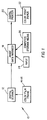
- Fig. 1 is a block diagram of a digital photofinishing system incorporating the present invention.
- Fig. 2 is a flow diagram of a preferred method of the present invention.
- Fig. 3 is a graphical view useful in explaining aspects of the present invention.
-
- Referring to Fig. 1, there is shown a block diagram of a
digital photofinishing system 10 incorporating the present invention. As shown,system 10 includes adigital scanner 12 for scanning color photographic media 14 to produce a digital color image of a color image frame 16 on color media 14. Color media 14 is a negative film.Image data manager 18 processes the digital image to optimize the image for printing the processed image byprinter 20 on colorhard copy media 22. Color hard copy media can be any high quality reflection or transmissive media, such as silver halide color paper, and media used in ink jet, thermal, electrophotographic printing processes. The operation ofscanner 12 andprinter 20 are described in greater detail below. - Image data manager (IDM) 18 processes the digital color image from
scanner 12.IDM 18 is preferably a digital computer having user input 24 (keyboard, mouse) and computer readablestorage media input 26. Computer readable storage media may comprise, for example, magnetic storage media, such as a magnetic floppy disc or magnetic tape; optical storage media, such as optical disc, optical tape or machine readable bar code; solid state electronic storage devices, such as read only memory (ROM) or random access memory (RAM); or any other physical device or medium employed to store a computer program. The digital image processing techniques described below can be readable storage media. Alternatively, some or all of the techniques may be incorporated into programmable gate arrays or other hard electronic devices. - The
scanner 12 for the production of digitally processed prints scans a 35 mm full frame image at a minimum resolution of m×n pixels. It would be preferred that the scanner produce a higher image resolution of, e.g., 2m×2n pixels so that "panoramic" images or enlargements can be printed with sufficient resolution without interpolation, The higher resolution is also preferred for the preparation of 5R prints. All magnifications higher than 5R will require higher resolution scans. - The scanner delivers the digitized data to the image processing algorithm as "printing density." A scanner that measures printing density has red, green, and blue effective spectral response that matches that of photographic paper in an optical printer. Photographic films are designed based on the expectation that the captured information in the film will be read by this type of red, green and blue spectral response characteristic.
- Even though the scanner is not considered part of the digital image processing path, some manipulations of the data may be required to deliver "printing density" to the processing algorithm. Two key steps are converting scanner densities to calibrated scanner densities, and converting the calibrated scanner densities to printing densities. Matrix operations may be required to perform these conversions, or a look-up-table can be used.
- The first step in the process is to convert the raw scanner numbers to calibrated scanner densities. If a matrix operation is used, an appropriate matrix correction model is shown below.

N rsx is raw scanner number andD sx is corrected scanner density. - The next process in the scanner converts calibrated scanner densities to calibrated printing densities. The process is implemented again with a matrix model that in this case can be up to a 3 x 10 matrix multiplication. An example is shown below.The output of the matrix multiplication is calibrated printing density.

D sx is calibrated scanner density, andD px is calibrated printing density. Either or both of these steps can be implemented with a 3D look-up-table. - According to a preferred method of the present invention as shown in Fig. 2, an image on photographic media (block 30) is scanned (by scanner 12) to produce a digital image (block 32). After conversion to printing density, the digital image is sequentially processed by
IDM 18 in an image processor section 33 with a scene balance algorithm (box 34) (See: Modern Exposure Determination for Customizing Photofinishing Printer Response," J. Appl. Photog. Eng., Vol. 5, No. 2, Spring 1979, pp. 93-104.), and a media (film) under-exposure gamma algorithm (box 35). In aprinter section 37, the digital image is further processed with print media characteristic curve mapping (box 36), image sharpening (box 38) and then digitally printed on hard copy media (box 40) bydigital printer 20. - Hard copy media includes media optimized for the print technology used, i.e., laser or CRT photographic printers, ink jet printer, thermal printer, electrophotographic printer, etc.
- In analytical section 41, a subsampled digital color image is created (box 42). The subsampled digital image is processed with a scene balance algorithm to determine a set of density shift values (box 44) and with a media/film underexposure gamma algorithm to increase the underexposure gamma of the image (box 45).
- The processing of
box 45 is effected as follows. The image is shifted to a new Dmin position so that the correction process produces no negative density values. A look-up table is applied to the sub-sampled image such that low film gamma information that is contained in the toe of the film sensitometric curve is changed in density to increase the gamma. The image is then shifted back to the original Dmin position (the two "shift" operations complement one another). The technique disclosed in U.S. Patent 5,134,573, issued July 28, 1992, inventor Goodwin, can be used. The shift values are then applied to the full resolution digital color image (box 46). - The look-up table used by the algorithm may be a universal table for all media types and conditions. Or it may be a function of media type, lab preference, or customer preference. If it is a function of media type, it may be accessed based on the DX code on the media.
- The look-up table that is applied to correct the gamma of the capture media in the under-exposure region may be obtained from a number of different sources. The look-up table may be encoded optically or magnetically on the capture media. The look-up table may be calculated by the software from reference exposure patches on the capture media. Media reference exposure patches are described in U.S. Patent 5,649,260. The look-up table or look-up table precursor data may be encoded on optical, magnetic, or other media that accompany the capture media. The look-up table may be selected or supplied, directly or indirectly, by the customer or processing lab. The look-up table may be accessed from a software embodiment database, based on the media type, lab preference, or customer preference. The look-up table may also be accessed via the intranet from an available repository, based on the media type, lab preference, or customer preference.
- U.S. Patent 5,134,573 teaches the calculation of correction look-up table with a limiting gamma enhancement value to avoid unwanted noise introduction. We have found that it is preferable in some cases to calculate the correction look-up table as a fraction, such as 0.5, of the gamma adjustment factor that is required to fully correct the media toe gamma to match that of the media in a normally exposed region.
- In the absence of an exposure-density sensitometry present on the specific media providing the image that are being processed, the look-up table may be derived from different media response approximates, such as media aim sensitometry. In general, in the absence of customer preference, media-type specific look-up tables provide higher quality images, and the most preferred are the media-type population averages for the processing lab.
- The process of operating a two stage film/media printing system has as its most imposing task that of finding a density value on the film exposure and mapping the densities on that negative to the media so that the best overall density and color balance are obtained. The process is best illustrated by tying together a series of reference points showing the connections from a scene object to the photographic reproduction of the object.
- Fig. 3, below, illustrates the concept of density tie points in our analysis of printing process. This process ties an initial target, usually a uniform gray card, to the photographic reproduction of that target. Test points are established for the initial exposure of the target object as an expected reference film density from a film reference exposure for the test object. The quadrant labeled "Printer" merely reflects the film reference density to the log exposure axis of the media. The test target will be assigned a density to be achieved for the reproduction of that object, or a density at the paper balance point. This point is characterized as the media reference exposure value and a media reference density value.
- The objective of the scene balance process is to first determine the film density value for the film reference exposure and to determine the difference between this film density value and the media reference exposure value. The difference, or Δ, is added to the film reference density. This process assures that the quadrant labeled "Print Through" will yield the appropriate print density in the final reproduction of the scene.
- Real photographic opportunities, or images, usually do not contain test objects that can be mapped in a formal process like that just described. Scene balance algorithms are designed to perform the task of estimating the reference film density, as if a gray card had been included in the scene. Once an estimate of the film reference density has been made, the process is duplicated just as described above. The examples show only one color record. Color films contain three records to capture the red, green, and blue information from a scene. Thus, the scene balance algorithms must perform two tasks. First estimate the overall density of the film image to that the best neutral density is obtained in the final print, or print through quadrant of the scene. Then the balance between the red, green, and blue exposure must be estimated.
- Before or after processing with the SBA, the full digital color image is processed with a media (film) under-exposure gamma adjustment algorithm to increase the under-exposure gamma of the full digital color image. A shift in the printing density data is performed so that a single column table can be used to shift the red, green, and blue pixel densities. In this instance, the red, green, and blue pixel printing density values are adjusted so that the film minimum densities values (Dmin) are all 0.5. All of the digitized data then is modified by a table look-up process such that image densities that occur near or in the film sensitometric toe region are actually reduced to increase the image information gamma. The table consists of a single column of numbers. The column represents the substitution values for the red, green and blue pixel values. In the final step of the gamma correction process, a shift is applied that restores the density values to the previous unnormalized Dmin values.
- The next step in the process is to map the balanced image through a hard copy media (color photographic paper) characteristic curve. The printing density values of the balanced image are mapped to the appropriate print density values for negative photographic print paper. The finished process produces an image that is color and density balanced, and in a print density metric. The photographic paper curve is balanced.
- The final step prior to actually printing the image is the sharpening process. An unsharp masking algorithm is applied to every image just prior to printing. The unsharp masking equation is as follows.The red, green, and blue images are all sharpened to the same level.

- The recommended value for β was established by adjusting the value upwards until pictures, when printed, began to appear with unacceptable levels of digital artifacts. These artifacts appeared as ringing, or halos, on edges yielding images that appear unnatural.
- This value of beta is then applied to a square wave target to measure the modulation transfer function for the final processed image. The test to establish the full system MTF response is as follows. First, a target is photographed using a color negative film. The original target has a square wave pattern of approximately 40% modulation. The spatial frequency response values for each frequency of square wave pattern is 100% through all of the system visible frequencies. The film image was scanned on the digital scanner to produce a 1024×1536 pixel digital image for subsequent processing. This image was processed through our SBA plus sharpening path and printed. The spatial frequency response of the final print was measured with a high resolution microdensitometer, and the data analyzed using a harmonic analysis process. Table 1 lists the red, green, and blue response measured in this test (average of four samples) and represents the maximum MTF before significant artifact production occurs.
- The MTF curve measured using this process represents the maximum spatial frequency of any digital processing system for Digital Photofinishing. This as the final print image is a combination of camera lens, film, scanner, algorithm, print engine, and print media. Any combination of these elements that yields an MTF curve of this result, or any result below the values listed in Table 1, will be considered as part of this invention. The set of parameters considered for this system, including the sharpening algorithm, are the maximum level of boost before going into a condition of oversharpening. Values of beta lower than that specified in the report are considered within the scope of this invention because these values also deliver prints that meet our printing requirements for making digital prints . If one of the system components is changed, then the beta value will be changed to assure that any final image produced by this digital path will achieve the upper limit MTF curve.
Maximum MTF Values Freq Red Green Blue 0.0 1.0000 1.0000 1.0000 0.5 0.9813 1.0500 1.0785 1.0 0.9680 1.1180 1.1423 1.5 0.8735 1.0840 1.0948 2.0 0.7118 0.924 0.9298 2.5 0.5263 0.7170 0.7170 3.0 0.3523 0.5380 0.5238 3.5 0.2225 0.3970 0.3725 4.0 0.1510 0.2910 0.2688 4.5 0.1150 0.2140 0.2023 5.0 0.0893 0.1610 0.1593 5.5 0.0690 0.1250 0.1308 6.0 0.0530 0.1000 0.1095 6.5 0.0410 0.0840 0.0945 Notes:
(1) The column labeled "Freq" is spatial frequency in cycles/mm on a 4R reflection print, and the columns labeled as colors are the response values for that color at each spatial frequency.
(2) The MTF values are given for a 4"×6" print, 250 dots per inch, and 1024×1536 pixels. - Psycho-physical experiments were conducted to compare these digital path prints to a convention optical printing path. The optically printed images were prepared using a
CLAS 35 optical printer running in the full order printing mode, thus emulating the SBA operating in our digital path. The scene balance algorithm parameters used in the digital and optical paths were the same so that similar prints could be prepared. Pairs of prints, digital and optical, were shown to a panel of three judges who were asked to choose the best print from the pair. In 75% of the pairs, the digital print was selected, citing sharpness as the reason. The remaining 25% were the optical prints selected because of grain build-up in the digital prints. - At this point in the process, the printing densities should be fully balanced and corrected. This image information can be printed through a simple printing density to print density look-up table.
- In the simplest case (printing density to print density), the printing density values are mapped to the appropriate print density values for a negative photographic paper. The finished process produces an image that is color and density balanced, and in a print density metric. We find the most preferred mapping from the balanced digital color negative image onto the characteristic curve of the aim AgX paper results from mapping reference RGB printing densities representing an achromatic middle gray onto achromatic RGB paper densities. These RGB paper densities are a function of the print material image dye spectra.
- The final step prior to actually printing the image is the sharpening process which has been described previously.
- At this stage in the process, the encoded data is sent to a printing device that renders, or prints, the information. A calibration process must be operating on this device such that the code values presented to the printer will yield the expected print densities.
- Printer calibration will be done as part of the image processing system maintenance such that test patch density differences between measured and expected densities of less than 0.01 are obtained. The simplest embodiment only requires a neutral scale calibration. In more complex applications a color calibration may be necessary.
- A series of uniform patches (at least 18) spanning the full range of printer code values are printed through an initial calibration LUT. This initial LUT must cover all those D/A count values that produce density on the print. The patch densities on the print are measured. With the initial LUT, the list of code values, respective densities of those patches, and the aim curve, a new calibration LUT can be calculated which should modify printing behavior according to the calibration aim.
- It will be appreciated that image sharpening can be effected at other points in the image processing chain. It will also be appreciated that the goal of the image processing described herein is to produce images via digital printing that are similar to, or better than, images produced by optically printing negative film images. This can be done in a straight forward manner as described herein when using digital hard copy media having similar image dye spectra to the image dye spectra of the hard copy media (silver halide color paper) used in optical printing.
- The invention has been described in detail with particular reference to certain preferred embodiments thereof, but it will be understood that variations and modifications can be effected within the spirit and scope of the invention.
-
- 10
- digital photofinishing system
- 12
- digital scanner
- 14
- color film
- 16
- color image frame
- 18
- image data manager
- 20
- printer
- 22
- color print paper
- 24
- input
- 26
- computer readable storage media input
- 30
- image on photographic media
- 32
- produce digital image
- 34
- process with scene balance algorithm
- 35
- under-exposure gamma algorithm
- 36
- print media characteristic curve mapping
- 38
- image sharpening
- 40
- digitally print image
- 42
- create subsampled digital image
- 44
- SBA density shift parameters
- 46
- full resolution digital image
Claims (9)
- A method of digital photofinishing comprising the steps of:producing a digital color image in optical printing densities of a color image captured on photographic media;increasing the under-exposure gamma of said digital color image using a media under-exposure gamma adjustment algorithm;processing said under-exposure gamma adjusted digital color image with a scene balance algorithm to produce a balanced digital color image;mapping said balanced digital color image through a hard copy media characteristic curve to produce a balanced digital image mapped to print densities of said hard copy media;sharpening said mapped balanced digital color image with a sharpening algorithm optimized to avoid unacceptable artifacts; anddigitally printing said sharpened digital color image onto hard copy media.
- The method of claim 1 wherein said producing step produces a digital image in optical printing densities of an image frame captured on transparent photographic negative or reversal film.
- The method of claim 1 wherein said processing step includes the steps of creating a subsampled digital color image of said digital image, processing said subsampled digital image with said scene balance algorithm to produce density shift parameters, and applying said density shift parameters to said full digital image to produce said balanced digital image.
- The method of claim 3 wherein said processing step includes the step of increasing the under-exposure gamma of said subsampled digital color image using a media under-exposure gamma adjustment algorithm.
- The method of claim 1 wherein in said mapping step said hard copy media is photographic paper and said hard copy media characteristic curve is photographic paper characteristic curve, and wherein in said printing step said hard copy media is photographic paper.
- The method of claim 1 wherein in said sharpening step said sharpening algorithm has a parameter which is adjusted to a value near the value where unacceptable levels of digital artifacts begin to appear in the printed image.
- A method of digital photofinishing comprising the steps of:producing a digital color negative image in optical printing densities of a color image captured on a color negative;increasing the under-exposure gamma of said digital color negative image using a negative film under-exposure gamma adjustment algorithm;processing the digital color negative image with a scene balance algorithm to produce a balanced digital color negative image;mapping said balanced digital color negative image through a hard copy media characteristic curve to produce a balanced digital positive color image;sharpening said mapped balanced digital color positive image with a sharpening algorithm optimized to avoid unacceptable artifacts; anddigitally printing said sharpened digital color image onto hard copy media.
- The method of claim 1 wherein said under-exposure gamma adjustment algorithm of said increasing step uses a look-up table which may be a universal table for all media types and conditions or which may be a function of media type, lab preference or customer preference.
- The method of claim 8 wherein said look-up table can be obtained from one or more of the following sources: recorded on the photographic media, calculated from reference exposure patches on the photographic media, recorded on optical, magnetic, or other media associated with the photographic media, selected or supplied directly or indirectly by the customer or processing lab, accessed from a software database based on the media type, lab preference or customer preference, or accessed via the internet or intranet from an available database, based on the media type, lab preference, or customer preference.
Applications Claiming Priority (2)
| Application Number | Priority Date | Filing Date | Title |
|---|---|---|---|
| US09/086,146 US6097471A (en) | 1998-05-28 | 1998-05-28 | Digital photofinishing system including film under-exposure gamma, scene balance, and image sharpening digital image processing |
| US86146 | 2002-02-28 |
Publications (3)
| Publication Number | Publication Date |
|---|---|
| EP0961486A2 true EP0961486A2 (en) | 1999-12-01 |
| EP0961486A3 EP0961486A3 (en) | 2002-05-15 |
| EP0961486B1 EP0961486B1 (en) | 2007-12-12 |
Family
ID=22196576
Family Applications (1)
| Application Number | Title | Priority Date | Filing Date |
|---|---|---|---|
| EP99201542A Expired - Lifetime EP0961486B1 (en) | 1998-05-28 | 1999-05-15 | Digital photofinishing system with digital image processing |
Country Status (4)
| Country | Link |
|---|---|
| US (1) | US6097471A (en) |
| EP (1) | EP0961486B1 (en) |
| JP (1) | JP2000050079A (en) |
| DE (1) | DE69937708T2 (en) |
Cited By (3)
| Publication number | Priority date | Publication date | Assignee | Title |
|---|---|---|---|---|
| US6781724B1 (en) | 2000-06-13 | 2004-08-24 | Eastman Kodak Company | Image processing and manipulation system |
| US6950608B2 (en) | 2003-12-23 | 2005-09-27 | Eastman Kodak Company | Capture of multiple interlaced images on a single film frame using micro-lenses and method of providing multiple images to customers |
| US7830428B2 (en) | 2007-04-12 | 2010-11-09 | Aptina Imaging Corporation | Method, apparatus and system providing green-green imbalance compensation |
Families Citing this family (13)
| Publication number | Priority date | Publication date | Assignee | Title |
|---|---|---|---|---|
| US7280251B1 (en) | 1996-02-26 | 2007-10-09 | Rah Color Technologies | System and method for calibrating color printers |
| US6628329B1 (en) * | 1998-08-26 | 2003-09-30 | Eastman Kodak Company | Correction of position dependent blur in a digital image |
| US6731397B1 (en) * | 1999-05-21 | 2004-05-04 | Foveon, Inc. | Method for storing and retrieving digital image data from an imaging array |
| EP1232418B1 (en) * | 1999-08-17 | 2004-10-13 | Eastman Kodak Company | Method and system for using calibration patches in electronic film processing |
| US7428011B1 (en) * | 1999-09-02 | 2008-09-23 | Fujifilm Corporation | Wide dynamic range electronic image recording and reproducing system |
| US7082227B1 (en) * | 1999-11-24 | 2006-07-25 | Baum Daniel R | Producing printed images having personalized features |
| US7102648B1 (en) | 2000-04-11 | 2006-09-05 | Rah Color Technologies Llc | Methods and apparatus for calibrating a color display |
| US7228797B1 (en) * | 2000-11-28 | 2007-06-12 | Sundberg-Ferar, Inc. | Cordless blind |
| US7062108B2 (en) * | 2001-06-12 | 2006-06-13 | Eastman Kodak Company | Method for estimating the appearance of noise in images |
| US6856702B2 (en) * | 2001-06-28 | 2005-02-15 | Andrew C. Gallagher | System and method for selecting an image processing path using estimated appearance of noise |
| US7006252B2 (en) * | 2001-10-17 | 2006-02-28 | Eastman Kodak Company | Image processing system and method that maintains black level |
| US7228004B2 (en) | 2002-09-05 | 2007-06-05 | Eastman Kodak Company | Method for sharpening a digital image |
| US20060181721A1 (en) * | 2005-02-11 | 2006-08-17 | Kulkarni Manish S | Motion picture content preview |
Citations (6)
| Publication number | Priority date | Publication date | Assignee | Title |
|---|---|---|---|---|
| US4866513A (en) * | 1985-07-04 | 1989-09-12 | Fuji Photo Film Co., Ltd. | Color contrast correction system for video images obtained from color film |
| US5233386A (en) * | 1990-10-01 | 1993-08-03 | Fuji Photo Film Co., Ltd. | Photosensitive material for managing condition, method of managing condition and apparatus for processing a photosensitive material |
| EP0639026A1 (en) * | 1988-01-08 | 1995-02-15 | Fuji Photo Film Co., Ltd. | Color film analyzing method and apparatus therefore |
| EP0660589A2 (en) * | 1993-12-21 | 1995-06-28 | Nec Corporation | Color image forming device capable of achieving a uniform and stable image quality for various recording media |
| EP0773470A1 (en) * | 1995-11-09 | 1997-05-14 | Fuji Photo Film Co., Ltd. | Image processing method for photographic printer |
| US6091861A (en) * | 1998-02-03 | 2000-07-18 | Eastman Kodak Company | Sharpening algorithm adjusted for measured exposure of photofinishing images |
Family Cites Families (8)
| Publication number | Priority date | Publication date | Assignee | Title |
|---|---|---|---|---|
| US4500919A (en) * | 1982-05-04 | 1985-02-19 | Massachusetts Institute Of Technology | Color reproduction system |
| US4945406A (en) * | 1988-11-07 | 1990-07-31 | Eastman Kodak Company | Apparatus and accompanying methods for achieving automatic color balancing in a film to video transfer system |
| US4979032A (en) * | 1988-12-27 | 1990-12-18 | Eastman Kodak Company | Color imaging apparatus producing on various image receptive materials a visually matched hard copy reproduction of a video image displayed |
| US5267030A (en) * | 1989-12-22 | 1993-11-30 | Eastman Kodak Company | Method and associated apparatus for forming image data metrics which achieve media compatibility for subsequent imaging application |
| JP3373508B2 (en) * | 1989-12-26 | 2003-02-04 | イーストマン コダック カンパニー | How to extend the linear range of an image captured on film |
| DE69319979T2 (en) * | 1992-09-08 | 1998-12-10 | Fuji Photo Film Co Ltd | Image processing system and method for faithful reproduction of the colors of objects on negative film |
| US5300381A (en) * | 1992-09-24 | 1994-04-05 | Eastman Kodak Company | Color image reproduction of scenes with preferential tone mapping |
| US5608542A (en) * | 1995-03-31 | 1997-03-04 | Eastman Kodak Company | Formatted digital index print system and method |
-
1998
- 1998-05-28 US US09/086,146 patent/US6097471A/en not_active Expired - Lifetime
-
1999
- 1999-05-15 EP EP99201542A patent/EP0961486B1/en not_active Expired - Lifetime
- 1999-05-15 DE DE69937708T patent/DE69937708T2/en not_active Expired - Lifetime
- 1999-05-27 JP JP11148924A patent/JP2000050079A/en active Pending
Patent Citations (6)
| Publication number | Priority date | Publication date | Assignee | Title |
|---|---|---|---|---|
| US4866513A (en) * | 1985-07-04 | 1989-09-12 | Fuji Photo Film Co., Ltd. | Color contrast correction system for video images obtained from color film |
| EP0639026A1 (en) * | 1988-01-08 | 1995-02-15 | Fuji Photo Film Co., Ltd. | Color film analyzing method and apparatus therefore |
| US5233386A (en) * | 1990-10-01 | 1993-08-03 | Fuji Photo Film Co., Ltd. | Photosensitive material for managing condition, method of managing condition and apparatus for processing a photosensitive material |
| EP0660589A2 (en) * | 1993-12-21 | 1995-06-28 | Nec Corporation | Color image forming device capable of achieving a uniform and stable image quality for various recording media |
| EP0773470A1 (en) * | 1995-11-09 | 1997-05-14 | Fuji Photo Film Co., Ltd. | Image processing method for photographic printer |
| US6091861A (en) * | 1998-02-03 | 2000-07-18 | Eastman Kodak Company | Sharpening algorithm adjusted for measured exposure of photofinishing images |
Cited By (3)
| Publication number | Priority date | Publication date | Assignee | Title |
|---|---|---|---|---|
| US6781724B1 (en) | 2000-06-13 | 2004-08-24 | Eastman Kodak Company | Image processing and manipulation system |
| US6950608B2 (en) | 2003-12-23 | 2005-09-27 | Eastman Kodak Company | Capture of multiple interlaced images on a single film frame using micro-lenses and method of providing multiple images to customers |
| US7830428B2 (en) | 2007-04-12 | 2010-11-09 | Aptina Imaging Corporation | Method, apparatus and system providing green-green imbalance compensation |
Also Published As
| Publication number | Publication date |
|---|---|
| DE69937708D1 (en) | 2008-01-24 |
| EP0961486A3 (en) | 2002-05-15 |
| DE69937708T2 (en) | 2008-11-27 |
| US6097471A (en) | 2000-08-01 |
| JP2000050079A (en) | 2000-02-18 |
| EP0961486B1 (en) | 2007-12-12 |
Similar Documents
| Publication | Publication Date | Title |
|---|---|---|
| US6097470A (en) | Digital photofinishing system including scene balance, contrast normalization, and image sharpening digital image processing | |
| EP0961482B1 (en) | Digital photofinishing system including digital image processing of alternative capture color photographic media | |
| US6233069B1 (en) | Digital photofinishing system including film under exposure gamma, scene balance, contrast normalization, and image sharpening digital image processing | |
| US6097471A (en) | Digital photofinishing system including film under-exposure gamma, scene balance, and image sharpening digital image processing | |
| US6091861A (en) | Sharpening algorithm adjusted for measured exposure of photofinishing images | |
| KR20010112622A (en) | An image processing and manipulation system | |
| US6163389A (en) | Digital photofinishing system including digital image processing of alternative capture color photographic media | |
| US5926291A (en) | Method of calculating color correcting condition and medium for storing the method | |
| US5995654A (en) | Digital photofinishing system including scene balance and image sharpening digital image processing | |
| US7215832B1 (en) | Retrieval system and image processing apparatus | |
| US20020131080A1 (en) | Print system | |
| JPH09261505A (en) | Color correction condition calculating method, printing, exposure quantity deciding method, image processing method, image processor, image forming device, printing, exposure device and storage medium | |
| JP3408770B2 (en) | Image processing device | |
| US6560374B1 (en) | Image processing apparatus | |
| US6639690B1 (en) | Print system | |
| JP3549413B2 (en) | Image processing method and image processing apparatus | |
| US6710896B1 (en) | Image processing apparatus | |
| JP2001086332A (en) | Image processor | |
| JPH11338062A (en) | Printing system | |
| JP3929210B2 (en) | Image processing method and apparatus | |
| JP3908216B2 (en) | Printing system | |
| US6614945B1 (en) | Image processing method and apparatus | |
| EP0902581B1 (en) | Print system | |
| JPH11298722A (en) | Print system | |
| JPH11341275A (en) | Image processor |
Legal Events
| Date | Code | Title | Description |
|---|---|---|---|
| PUAI | Public reference made under article 153(3) epc to a published international application that has entered the european phase |
Free format text: ORIGINAL CODE: 0009012 |
|
| AK | Designated contracting states |
Kind code of ref document: A2 Designated state(s): AT BE CH CY DE DK ES FI FR GB GR IE IT LI LU MC NL PT SE |
|
| AX | Request for extension of the european patent |
Free format text: AL;LT;LV;MK;RO;SI |
|
| PUAL | Search report despatched |
Free format text: ORIGINAL CODE: 0009013 |
|
| AK | Designated contracting states |
Kind code of ref document: A3 Designated state(s): AT BE CH CY DE DK ES FI FR GB GR IE IT LI LU MC NL PT SE |
|
| AX | Request for extension of the european patent |
Free format text: AL;LT;LV;MK;RO;SI |
|
| 17P | Request for examination filed |
Effective date: 20021021 |
|
| AKX | Designation fees paid |
Designated state(s): DE FR GB |
|
| GRAP | Despatch of communication of intention to grant a patent |
Free format text: ORIGINAL CODE: EPIDOSNIGR1 |
|
| GRAS | Grant fee paid |
Free format text: ORIGINAL CODE: EPIDOSNIGR3 |
|
| GRAA | (expected) grant |
Free format text: ORIGINAL CODE: 0009210 |
|
| AK | Designated contracting states |
Kind code of ref document: B1 Designated state(s): DE FR GB |
|
| REG | Reference to a national code |
Ref country code: GB Ref legal event code: FG4D |
|
| REF | Corresponds to: |
Ref document number: 69937708 Country of ref document: DE Date of ref document: 20080124 Kind code of ref document: P |
|
| ET | Fr: translation filed | ||
| PLBE | No opposition filed within time limit |
Free format text: ORIGINAL CODE: 0009261 |
|
| STAA | Information on the status of an ep patent application or granted ep patent |
Free format text: STATUS: NO OPPOSITION FILED WITHIN TIME LIMIT |
|
| 26N | No opposition filed |
Effective date: 20080915 |
|
| PGFP | Annual fee paid to national office [announced via postgrant information from national office to epo] |
Ref country code: GB Payment date: 20130425 Year of fee payment: 15 Ref country code: DE Payment date: 20130531 Year of fee payment: 15 |
|
| PGFP | Annual fee paid to national office [announced via postgrant information from national office to epo] |
Ref country code: FR Payment date: 20130531 Year of fee payment: 15 |
|
| REG | Reference to a national code |
Ref country code: DE Ref legal event code: R119 Ref document number: 69937708 Country of ref document: DE |
|
| GBPC | Gb: european patent ceased through non-payment of renewal fee |
Effective date: 20140515 |
|
| REG | Reference to a national code |
Ref country code: DE Ref legal event code: R119 Ref document number: 69937708 Country of ref document: DE Effective date: 20141202 |
|
| REG | Reference to a national code |
Ref country code: FR Ref legal event code: ST Effective date: 20150130 |
|
| PG25 | Lapsed in a contracting state [announced via postgrant information from national office to epo] |
Ref country code: DE Free format text: LAPSE BECAUSE OF NON-PAYMENT OF DUE FEES Effective date: 20141202 |
|
| PG25 | Lapsed in a contracting state [announced via postgrant information from national office to epo] |
Ref country code: FR Free format text: LAPSE BECAUSE OF NON-PAYMENT OF DUE FEES Effective date: 20140602 Ref country code: GB Free format text: LAPSE BECAUSE OF NON-PAYMENT OF DUE FEES Effective date: 20140515 |