EP0961587B1 - Helical osteosynthetic implant - Google Patents
Helical osteosynthetic implant Download PDFInfo
- Publication number
- EP0961587B1 EP0961587B1 EP97953762A EP97953762A EP0961587B1 EP 0961587 B1 EP0961587 B1 EP 0961587B1 EP 97953762 A EP97953762 A EP 97953762A EP 97953762 A EP97953762 A EP 97953762A EP 0961587 B1 EP0961587 B1 EP 0961587B1
- Authority
- EP
- European Patent Office
- Prior art keywords
- blades
- implant according
- nail
- bone
- helical
- Prior art date
- Legal status (The legal status is an assumption and is not a legal conclusion. Google has not performed a legal analysis and makes no representation as to the accuracy of the status listed.)
- Expired - Lifetime
Links
Images


Classifications
-
- A—HUMAN NECESSITIES
- A61—MEDICAL OR VETERINARY SCIENCE; HYGIENE
- A61B—DIAGNOSIS; SURGERY; IDENTIFICATION
- A61B17/00—Surgical instruments, devices or methods, e.g. tourniquets
- A61B17/56—Surgical instruments or methods for treatment of bones or joints; Devices specially adapted therefor
- A61B17/58—Surgical instruments or methods for treatment of bones or joints; Devices specially adapted therefor for osteosynthesis, e.g. bone plates, screws, setting implements or the like
- A61B17/68—Internal fixation devices, including fasteners and spinal fixators, even if a part thereof projects from the skin
- A61B17/74—Devices for the head or neck or trochanter of the femur
- A61B17/742—Devices for the head or neck or trochanter of the femur having one or more longitudinal elements oriented along or parallel to the axis of the neck
- A61B17/744—Devices for the head or neck or trochanter of the femur having one or more longitudinal elements oriented along or parallel to the axis of the neck the longitudinal elements coupled to an intramedullary nail
-
- A—HUMAN NECESSITIES
- A61—MEDICAL OR VETERINARY SCIENCE; HYGIENE
- A61B—DIAGNOSIS; SURGERY; IDENTIFICATION
- A61B17/00—Surgical instruments, devices or methods, e.g. tourniquets
- A61B17/56—Surgical instruments or methods for treatment of bones or joints; Devices specially adapted therefor
- A61B17/58—Surgical instruments or methods for treatment of bones or joints; Devices specially adapted therefor for osteosynthesis, e.g. bone plates, screws, setting implements or the like
- A61B17/68—Internal fixation devices, including fasteners and spinal fixators, even if a part thereof projects from the skin
- A61B17/74—Devices for the head or neck or trochanter of the femur
- A61B17/742—Devices for the head or neck or trochanter of the femur having one or more longitudinal elements oriented along or parallel to the axis of the neck
- A61B17/746—Devices for the head or neck or trochanter of the femur having one or more longitudinal elements oriented along or parallel to the axis of the neck the longitudinal elements coupled to a plate opposite the femoral head
Definitions
- the invention relates to an implant for setting a broken bone according to the preamble of claim 1 as known from the document SU-A-1 071 298. It refers in particular to an implant for osteosynthesis of stable and unstable fractures of the neck and intertrochanteric region of the femur.
- femoral fractures commonly in the femoral neck and intertrochanteric regions. These fractures are normally treated by inserting a nail or hip screw from the side of the femur, through the neck, and into the femoral head. The nail or screw is then fixed to a side plate, that is fastened to the outside of the femur shaft, or to an intramedullary nail, that is inserted through the femur shaft. Both the side plate and the intramedullary nail may by secured to the femur shaft with bone screws.
- an sharp implanted nail or hip screw may cut through and penetrate the femoral head or neck; or a nail, hip screw, side plate, or intramedullary nail may bend or break under load where the contact between bone fragments is insufficient for the bone itself to carry the patient's weight.
- Collapsible implants have been developed to maximize bone to bone contact by permitting bone fragments to migrate towards one another.
- Examples in the prior art include the Richards-type compression hip-screw and the Kenn-type nail.
- Richards screws comprise a long, smooth shaft and external threads at the tip.
- Kenn nails comprise a wide, tri-flanged tip at the end of a smooth shaft. In both examples, the nail or screw implanted through the neck of the femur is allowed to slide back through the side plate or intramedullary nail as the bone fragments move together under a load.
- these known implants are laterally stiff. Their sharp ends may cut sideways through the cancellous tissue of a femoral head after implantation and migrate within the bone, either piercing the surface of the femur or simply no longer retaining proper alignment of bone fragments.
- single, helical blades were developed, such as the SPIRAL BLADE brand, currently sold by Synthes, Paoli, PA, and such as disclosed in U.S. Patent Nos. 5,300,074 and 4,978,349. These blades are twisted about 90° along their length and have a substantially uniform width.
- the distal end of the blade When implanted into the neck and head of a femur, the distal end of the blade lies in parallel with the femur shaft, and the proximal end lies perpendicularly to the shaft. In this position, the load on the head acts on relatively flexible, large, flat surface, reducing the pressure on the cancellous tissue and diminishing the tendency of the implant to further cut through the bone once implanted.
- the distal end being aligned with the femoral shaft, provides a higher bending stiffness than the tip to sufficiently support the blade. Also, unlike previous nails and screws, these blades require little or no material removal in the femoral head, prior to implantation, where the amount of bone is critical.
- the invention as claimed aims at solving the above described problems.
- the present invention solves these problems by providing an implant as defined in claim 1.
- the invention relates to a dynamic osteosynthetic-implant that minimizes the tendency to cut through the cancellous bone tissue after implantation and provides the required stiffness to maintain the relative orientation of the bone fragments.
- One implant according to the invention includes a plurality of helically twisted blades fixed to one another along a common helical axis. At least two of the blades define an angle of less than 180° in a plane disposed perpendicularly to the helical axis.
- the blades are preferably slidably engageable to a first member, such as a side plate or an intramedullary nail, that is itself engageable to the shaft of a femur.
- These blades provide the implant with a relatively flexible, large area, proximal end, but which gradually becomes stiffer towards its distal portion for additional support.
- two perpendicular pairs of oppositely oriented blades are helically twisted by at least about 30°.
- One pair of blades tapers towards its distal end; the other pair has substantially uniform widths.
- the distal ends of the uniform blades are oriented in parallel to the femoral shaft, while the distal ends of the tapered blades are oriented perpendicularly to the shaft.
- the respective proximal ends are oriented at about 90° of helical twist to their distal ends.
- the proximal end of the implant provides a large surface normal to the principal downward load on the head of the femur and is more compliant than the distal portion of the implant, with the distal portion having increased bending stiffness in all directions.
- the angle formed between any two adjacent blades, together with the portions of the blades normal to a shearing load on the bone resist the tendency of the implant to cut out through the bone under such a load.
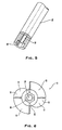
- an osteosynthetic nail 8 comprises a plurality of helically twisted blades 10 and 12 that are fixed to a proximal portion 14 of a shaft 16.
- distal and proximal are defined such that a proximal portion of an element is preferably located closer to the central part of the body than its distal portion.
- the shaft 16 is coaxial with the common helical axis of the blades 10 and 12.
- the blades 10 and 12 are substantially flat and may have sharp proximal ends. Their helical twist is at least about 30°, preferably from about 45 to 120° and most preferably about 90°.
- the helical rate of twist is such that nail 8 may be driven into a femur from the distal end of the nail 8. After implantation, this twist also inhibits nail 8 from sliding forwards or backwards along its helical axis with respect to the femoral head.
- the preferred embodiment comprises a pair of uniform blades 10 disposed on opposite sides of the helical axis and exhibiting a substantially uniform width, and a tapered pair of blades 12 disposed on opposite sides of the helical axis and substantially at right angles to the uniform blades 10.
- the angle 17 defined between at least two adjacent blades at any station along the helix may be any angle of less than 180°. Preferably, this angle is between 30 and 150°, and more preferably between 60 and 120°. The most preferable angle when four blades are used is 90°.
- the tapered blades 12 are widest at their distal ends 18 and taper down, in the direction of their proximal ends 20, until they lie flush with the outer surface of the proximal portion 14 of the shaft 16. Only one of the two proximal ends 20 of the blades 12 is visible in FIG. 1. From this vantage, the other is hidden behind the shaft 16.
- a cannulation 24 extends along the inner length of shaft 16.
- the cannulation 24 is sized to permit the insertion of a guide wire (not shown) to aid in the alignment of the nail during the implantation procedure as is commonly known in the art.
- FIG. 2 is a view from the proximal end of the nail which illustrates the helical shape of blades 10 and 12 and the taper of blades 12. It also shows the angle 17 formed between the blades 10 and 12. From this view, the distal ends 18 of the tapered blades 12 are directly behind the proximal tips of the uniform blades 10 and are thus hidden from view.
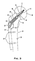
- FIG. 3 an embodiment that employs a side plate 26 is shown in a preferred implantation orientation.
- Side plate 26 is aligned with the shaft 28 of femur 29 and is securable to the outside thereof with fasteners 30, as shown in FIG. 3.
- a portion of the side plate 26, in one embodiment, may slide vertically with respect to fasteners 30 to -allow for vertical compression of the bone fragments.
- the proximal portion 22 of shaft 16 is telescopically slideable within a cylindrical sleeve 32 that is fixed to the side plate 26 at an angle 33 that will be generally between 90° and 150°, but that may be selected according to the anatomy of the patient.
- the side plate may be configured and dimensioned as a fixed plate that does not vertically move with respect to the fasteners.
- the length, width and other dimensions of either the fixed or slidable plate can be selected by one of ordinary skill in the art.
- sleeve 32 penetrates the side of the femur 29 towards the femur neck 34 and head 36.
- the distal portion 22 of shaft 16 in this embodiment has a larger outer diameter than does the proximal portion 14.
- This distal portion 22 is slidably engaged within sleeve 32 such that the distal ends of blades 10 and 12 are separated from the proximal end 38 of the sleeve. This separation enables the nail 8 to slide back into the sleeve 32 as the femur head 36 is compressed distally in the direction of the helical axis. This prevents the blades 10 and 12 from further cutting the head 36 after implantation.
- the nail 8 is implanted inside the neck 34 and head 36 of the femur 29.
- the distal portions of the uniform blades 10 are oriented in parallel to the shaft 28 of the femur, while the distal portions 18 of the tapered blades 12 are perpendicular to the femur shaft 28.
- uniform blades 10 are perpendicular to the femur shaft while tapered blades 12 and proximal ends 20 are parallel to the femur shaft 28.
- the wide proximal portions of the uniform blades 10 provides a large surface normal to the principal downward load imposed on the femoral head 36 when the patient stands and ambulates. This reduces the pressure on the cancellous tissue within the femur 29 and resists the tendency to cut through the bone cortex.
- the distal portions of the uniform blades 10, aligned with the principal load increase the bending stiffness of the shaft 16 resisting that load, and efficiently transfer the load to the side plate 26.
- the taper in the tapered blades 12 affords additional stiffness in their distal portions 18, where blades 12 have a larger width, but retains the compliancy of the nail 8 at the tapered proximal ends 20.
- the proximal part of the nail 8 may flex, rather than carve through, or crush, the bone tissue.
- the extra surface area furnished by tapered blades 12 also counter any propensity of the blades 10 and 12 to migrate laterally relative through the bone 29.
- the tissue will be driven into the angles formed between adjacent blades 10 and 12, further resisting nail 8 migration.
- the outer diameter of sleeve 32 is about the size of the widest portion of nail 8 so that nail 8 may fit easily through a hole drilled for insertion of the sleeve 32, making it easier to achieve the above orientation.
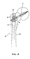
- FIG. 4 An alternative embodiment is shown in FIG. 4.
- This embodiment utilizes an intramedullary nail 40 implanted in the femoral shaft 28.
- the nail 8 may slide telescopically within a channel 42 inside the intramedullary nail 40.
- the channel 42 defines an angle 44 with the length of the intramedullary nail 40 of generally between 90° and 150°, which may be chosen according to shape of the femur.
- the intramedullary nail 40 is inserted into the bone first.
- the nail 8 is then implanted through the side of the femur 29 through a hole drilled merely up to the depth of the side surface of the intramedullary nail 40.
- Helical groves 46 extend radially from channel 42 and are shaped to receive blades 10 and 12. As the nail 8 is hammered into the bone, as commonly done by persons skilled in the art, blades 10 and 12 slide through grooves 46.
- the preferred implantation orientation resembles that of the side-plate embodiment.
- the nail 8 is positioned in the same relationship to the femur 29 and shares the same advantages.
- the distal end of the nail 8 defines a hexagonal cavity 48 concentric with the proximal base of the shaft 16 and the cannulation 24.
- This cavity 48 is shaped to receive the tip of an instrument, normally used in the art, designed to ease rotational orientation of the nail during implantation.
- the cavity 48 may be shaped differently depending on the instrument used. For, example, instead of a central cavity, the distal base and sides of shaft 16 may have indentations or raised portions to fit the instrument.
- the length and proportions of the elements of the invention may be selected by the surgeon according to the anatomy of the patient. Examples of selectable dimensions include the length of nails 8 and sizes of side plate 26 or intramedullary nail 40. Also, other embodiments may contain a different number of blades, if desired.
Abstract
Description
Claims (17)
- Implant for setting a broken bone (29) comprising a nail (8) having a plurality of helically twisted blades (10,12) for implantation in a bone fragment, said blades (10,12) being fixed to one another and aligned along a common helical axis, at least two of said blades defining an angle of less than 180° in a plane disposed perpendicularly to said helical axis,
characterized in that
said helical blades (10,12) are twisted by at least about 30° along said helical axis and comprise at least one tapered blade (12) tapering towards its proximal end to be inserted into the bone, said tapered blade having proximal and distal widths being measured relative to said helical axis, said distal width being greater than said proximal width. - Implant according to claim 1 further comprising a securing member (26,40) being securable to an elongate portion (28) of the bone (29), said blades (10,12) being engageable to said securing member (26,40).
- Implant according to claim 1 or 2, characterized in that said blades (10,12) are substantially flat and said at least two blades (10,12) define an angle (17) of between 30° and 150°.
- Implant according to one of the claims 1 to 3, characterized in that said helical blades (10,12) have a rate of helical twist such that they can be driven into a bone (29), and said at least two blades (10,12) define an angle (17) of between 60° and 120°.
- Implant according to one of the claims 2 to 4, characterized in that said distal width being disposed toward said securing member (26,40).
- Implant according to one of the claims 1 to 5, characterized in that said at least one tapered blade (12) is twisted by about 45° to 120° along said helical axis.
- Implant according to one of the claims 1 to 6, characterized in that said tapered blade (12) is twisted by about 90° and said nail (8) may be implanted such that the distal width of said tapered blade (12) is parallel to the elongate portion (28) of the bone (29).
- Implant according to one of the claims 2 to 7, characterized in that the blades (10,12) are movably engaged to the securing member (26,40).
- Implant according to one of the claims 1 to 8, characterized in that the blades (10,12) are slidably engaged to the securing member (26,40) in a direction parallel to said helical axis permitting compression of bone fragments.
- Implant according to one of the claims 1 to 9, characterized in that it further comprises a telescoping portion (22) of the nail (8) which is telescopically engageable to the securing member (26).
- Implant according to one of the claims 2 to 10, characterized in that said securing member (26,40) comprises a sleeve (32) for receiving said nail (8) preferably a telescoping portion (22) of said nail (8).
- Implant according to claim 11, characterized in that said sleeve (32) comprises an outer sleeve diameter; and said helical blades (10,12) define a helical diameter which is at most about as large as said outer sleeve diameter.
- Implant according to claim 11 or 12, characterized in that said securing member (26,40) defines helical grooves (46) extending from an inside portion of the sleeve (32) and being aligned therewith, said helical blades (10,12) being slideable within said grooves (32).
- Implant according to one of the claims 1 to 13, characterized in that nail (8) further comprises a hollow shaft (16) for receiving a guide wire, said hollow shaft (16) extending coaxially with said helical axis.
- Implant according to one of the claims 2 to 14, characterized in that said securing member (26) is securable to an outside portion (28) of the elongate portion of the bone (29).
- Implant according to one of the claims 2 to 15, characterized in that said securing member (40) comprises an intramedullary nail for insertion within the elongate portion (28) of the bone (29), in a direction substantially parallel thereto.
- Implant according to one of the claims 2 to 16, characterized in that said securing member (26,40) and said helical axis define an angle of between about 90° and 150°.
Applications Claiming Priority (3)
| Application Number | Priority Date | Filing Date | Title |
|---|---|---|---|
| US08/782,231 US5741256A (en) | 1997-01-13 | 1997-01-13 | Helical osteosynthetic implant |
| PCT/EP1997/006863 WO1998030164A1 (en) | 1997-01-13 | 1997-12-09 | Helical osteosynthetic implant |
| US782231 | 2004-02-19 |
Publications (2)
| Publication Number | Publication Date |
|---|---|
| EP0961587A1 EP0961587A1 (en) | 1999-12-08 |
| EP0961587B1 true EP0961587B1 (en) | 2003-10-01 |
Family
ID=25125427
Family Applications (1)
| Application Number | Title | Priority Date | Filing Date |
|---|---|---|---|
| EP97953762A Expired - Lifetime EP0961587B1 (en) | 1997-01-13 | 1997-12-09 | Helical osteosynthetic implant |
Country Status (12)
| Country | Link |
|---|---|
| US (2) | US5741256A (en) |
| EP (1) | EP0961587B1 (en) |
| JP (1) | JP4131989B2 (en) |
| CN (1) | CN1158974C (en) |
| AT (1) | ATE250892T1 (en) |
| AU (1) | AU712089B2 (en) |
| CA (1) | CA2276290C (en) |
| DE (1) | DE69725342T2 (en) |
| ES (1) | ES2207761T3 (en) |
| HK (1) | HK1021930A1 (en) |
| TW (1) | TW391874B (en) |
| WO (1) | WO1998030164A1 (en) |
Cited By (2)
| Publication number | Priority date | Publication date | Assignee | Title |
|---|---|---|---|---|
| WO2008064665A1 (en) | 2006-12-02 | 2008-06-05 | Gernot Teichmann | Device for producing a helical recess in the jawbone |
| EP3391841A1 (en) | 2017-04-20 | 2018-10-24 | Stöckli Group AG | Longitudinal bone implant |
Families Citing this family (139)
| Publication number | Priority date | Publication date | Assignee | Title |
|---|---|---|---|---|
| US8070786B2 (en) * | 1993-01-21 | 2011-12-06 | Acumed Llc | System for fusing joints |
| US9161793B2 (en) | 1993-01-21 | 2015-10-20 | Acumed Llc | Axial tension screw |
| EP0917449B1 (en) * | 1996-07-31 | 2003-02-05 | Synthes Ag Chur | Device for attaching fractured hip-joint heads |
| US6648890B2 (en) | 1996-11-12 | 2003-11-18 | Triage Medical, Inc. | Bone fixation system with radially extendable anchor |
| US6632224B2 (en) | 1996-11-12 | 2003-10-14 | Triage Medical, Inc. | Bone fixation system |
| EP0948293B1 (en) * | 1996-12-02 | 2002-09-25 | SYNTHES AG Chur | Flat intramedullary nail |
| EP1006918B1 (en) * | 1997-01-14 | 2007-01-03 | Research Corporation Technologies, Inc | Bone fixation pin with rotary cutting tip |
| WO1999044528A1 (en) * | 1998-03-05 | 1999-09-10 | Synthes Ag Chur | Intramedullary nail with locking hole |
| DE29804268U1 (en) | 1998-03-11 | 1998-05-14 | Synthes Ag | Spiral blade insertion instrument |
| WO2001034045A1 (en) | 1999-11-11 | 2001-05-17 | Synthes Ag Chur | Radially expandable intramedullary nail |
| AU2001231272A1 (en) * | 2000-02-02 | 2001-08-14 | Owen A. Nelson | An orthopedic implant used to repair intertrochanteric fractures and a method for inserting the same |
| US6533789B1 (en) * | 2000-04-04 | 2003-03-18 | Synthes (Usa) | Device for rotational stabilization of bone segments |
| US6409730B1 (en) | 2000-05-31 | 2002-06-25 | Synthes (Usa) | Humeral spiral blade |
| AU2001216855A1 (en) * | 2000-12-08 | 2002-06-18 | Synthes Ag, Chur | Device for fixing bones, particularly vertebral bodies, in relation to one another |
| US6511481B2 (en) | 2001-03-30 | 2003-01-28 | Triage Medical, Inc. | Method and apparatus for fixation of proximal femoral fractures |
| US6887243B2 (en) | 2001-03-30 | 2005-05-03 | Triage Medical, Inc. | Method and apparatus for bone fixation with secondary compression |
| US7144413B2 (en) | 2001-04-20 | 2006-12-05 | Synthes (U.S.A.) | Graft fixation system and method |
| US6835197B2 (en) * | 2001-10-17 | 2004-12-28 | Christoph Andreas Roth | Bone fixation system |
| US8828067B2 (en) * | 2001-10-18 | 2014-09-09 | Orthoip, Llc | Bone screw system and method |
| US6685706B2 (en) * | 2001-11-19 | 2004-02-03 | Triage Medical, Inc. | Proximal anchors for bone fixation system |
| DE20208922U1 (en) * | 2002-06-05 | 2003-10-09 | Stryker Trauma Gmbh | The neck screw |
| US6793678B2 (en) | 2002-06-27 | 2004-09-21 | Depuy Acromed, Inc. | Prosthetic intervertebral motion disc having dampening |
| WO2004008949A2 (en) | 2002-07-19 | 2004-01-29 | Triage Medical, Inc. | Method and apparatus for spinal fixation |
| US7179260B2 (en) * | 2003-09-29 | 2007-02-20 | Smith & Nephew, Inc. | Bone plates and bone plate assemblies |
| AU2002328243A1 (en) * | 2002-10-01 | 2004-04-23 | Synthes Ag Chur | Device for fixing bones |
| ATE378012T1 (en) * | 2002-10-29 | 2007-11-15 | Synthes Gmbh | DEVICE FOR TREATING FRACTURES OF THE FEMUR |
| US7070601B2 (en) | 2003-01-16 | 2006-07-04 | Triage Medical, Inc. | Locking plate for bone anchors |
| BR0318151A (en) * | 2003-03-07 | 2006-02-21 | Synthes Ag | locking screw for an intramedullary grip |
| WO2004098453A2 (en) * | 2003-05-06 | 2004-11-18 | Triage Medical, Inc. | Proximal anchors for bone fixation system |
| US7951176B2 (en) * | 2003-05-30 | 2011-05-31 | Synthes Usa, Llc | Bone plate |
| BR0318327B1 (en) * | 2003-06-12 | 2013-06-18 | Surgical claw. | |
| ES2348003T3 (en) * | 2003-06-12 | 2010-11-26 | Synthes Gmbh | SURGICAL KEY. |
| DE50311031D1 (en) * | 2003-07-30 | 2009-02-12 | Synthes Gmbh | SURGICAL NAIL |
| US11259851B2 (en) | 2003-08-26 | 2022-03-01 | DePuy Synthes Products, Inc. | Bone plate |
| BR0318428A (en) | 2003-08-26 | 2006-08-01 | Synthes Gmbh | bone plate |
| WO2005020830A1 (en) | 2003-08-29 | 2005-03-10 | Synthes Gmbh | Intramedullary nail |
| US7799030B2 (en) * | 2003-09-08 | 2010-09-21 | Smith & Nephew, Inc. | Orthopaedic plate and screw assembly |
| US20050055024A1 (en) * | 2003-09-08 | 2005-03-10 | James Anthony H. | Orthopaedic implant and screw assembly |
| US7780667B2 (en) * | 2003-09-08 | 2010-08-24 | Smith & Nephew, Inc. | Orthopaedic plate and screw assembly |
| KR101050877B1 (en) * | 2003-09-08 | 2011-07-20 | 신세스 게엠바하 | Bone fixation device |
| KR101036055B1 (en) * | 2003-09-18 | 2011-05-19 | 신세스 게엠바하 | Device for treating femoral fractures |
| US8105367B2 (en) * | 2003-09-29 | 2012-01-31 | Smith & Nephew, Inc. | Bone plate and bone plate assemblies including polyaxial fasteners |
| CA2545487C (en) * | 2003-10-21 | 2012-05-01 | Synthes (U.S.A.) | Intramedullary nail |
| US8574268B2 (en) | 2004-01-26 | 2013-11-05 | DePuy Synthes Product, LLC | Highly-versatile variable-angle bone plate system |
| US11291484B2 (en) | 2004-01-26 | 2022-04-05 | DePuy Synthes Products, Inc. | Highly-versatile variable-angle bone plate system |
| BRPI0418604B8 (en) * | 2004-03-03 | 2021-06-22 | Synthes Gmbh | bone fixative component |
| US8070750B2 (en) | 2004-03-05 | 2011-12-06 | Depuy Mitek, Inc. | Tunnel notcher and guidewire delivery device |
| WO2005096977A1 (en) * | 2004-04-12 | 2005-10-20 | Navin Thakkar | An implant assembly for proximal femoral fracture |
| ATE426366T1 (en) * | 2004-06-22 | 2009-04-15 | Synthes Gmbh | INTRAMEDULLAR INTRAMEDULLAR NAIL |
| WO2006000109A1 (en) * | 2004-06-24 | 2006-01-05 | Synthes Gmbh | Intramedullary nail |
| US8066706B2 (en) * | 2004-06-30 | 2011-11-29 | Synthes Usa, Llc | Surgical nail |
| WO2006023793A2 (en) * | 2004-08-20 | 2006-03-02 | Triage Medical, Inc. | Method and apparatus for delivering an agent |
| US8287541B2 (en) | 2005-05-18 | 2012-10-16 | Sonoma Orthopedic Products, Inc. | Fracture fixation device, tools and methods |
| CA2608693A1 (en) | 2005-05-18 | 2006-11-23 | Sonoma Orthopedic Products, Inc. | Minimally invasive actuable bone fixation devices, systems and methods of use |
| US8961516B2 (en) | 2005-05-18 | 2015-02-24 | Sonoma Orthopedic Products, Inc. | Straight intramedullary fracture fixation devices and methods |
| US9060820B2 (en) | 2005-05-18 | 2015-06-23 | Sonoma Orthopedic Products, Inc. | Segmented intramedullary fracture fixation devices and methods |
| ES2346670T3 (en) * | 2005-08-15 | 2010-10-19 | Synthes Gmbh | OSTEOSYNTHESIS DEVICE. |
| US7955358B2 (en) | 2005-09-19 | 2011-06-07 | Albert Todd J | Bone screw apparatus, system and method |
| WO2007038560A1 (en) * | 2005-09-28 | 2007-04-05 | Smith & Nephew, Inc. | Instrumentation for reducing fractures , particularly femoral neck |
| CA2624091C (en) * | 2005-12-22 | 2011-08-16 | Hugh S. West, Jr. | Bone anchors for use in attaching soft tissue to bone |
| EP2018127B1 (en) * | 2006-04-21 | 2010-05-19 | Synthes GmbH | Hip helical implant |
| US20080003255A1 (en) | 2006-05-10 | 2008-01-03 | Synthes (Usa) | Method for augmenting, reducing, and repairing bone with thermoplastic materials |
| US20090198237A1 (en) * | 2006-05-10 | 2009-08-06 | David Downey | Method for augmenting, reducing, and repairing bone with thermoplastic materials |
| DE102006057019B4 (en) * | 2006-08-21 | 2008-07-31 | Teichmann, Gernot, Dr. Dr. | Device for producing a helical recess in the jawbone |
| US8758345B2 (en) * | 2006-09-22 | 2014-06-24 | Christopher G. Sidebotham | Interlocking nail geometry and method of use |
| JP4978906B2 (en) * | 2006-10-17 | 2012-07-18 | 周 中村 | Fracture fixation device for femoral trochanteric fracture |
| AU2007323566A1 (en) | 2006-11-22 | 2008-05-29 | Sonoma Orthopedic Products, Inc. | Fracture fixation device, tools and methods |
| US8105382B2 (en) | 2006-12-07 | 2012-01-31 | Interventional Spine, Inc. | Intervertebral implant |
| US7909882B2 (en) | 2007-01-19 | 2011-03-22 | Albert Stinnette | Socket and prosthesis for joint replacement |
| US8317845B2 (en) * | 2007-01-19 | 2012-11-27 | Alexa Medical, Llc | Screw and method of use |
| US7918853B2 (en) * | 2007-03-20 | 2011-04-05 | Smith & Nephew, Inc. | Orthopaedic plate and screw assembly |
| US7998176B2 (en) | 2007-06-08 | 2011-08-16 | Interventional Spine, Inc. | Method and apparatus for spinal stabilization |
| US8900307B2 (en) | 2007-06-26 | 2014-12-02 | DePuy Synthes Products, LLC | Highly lordosed fusion cage |
| EP2471493A1 (en) | 2008-01-17 | 2012-07-04 | Synthes GmbH | An expandable intervertebral implant and associated method of manufacturing the same |
| GB2460909B (en) * | 2008-01-28 | 2010-09-08 | Mark B Sommers | Bone Nail |
| KR20110003475A (en) | 2008-04-05 | 2011-01-12 | 신세스 게엠바하 | Expandable intervertebral implant |
| EP2341857A2 (en) | 2008-09-26 | 2011-07-13 | Sonoma Orthopedic Products, Inc. | Bone fixation device, tools and methods |
| US9526620B2 (en) | 2009-03-30 | 2016-12-27 | DePuy Synthes Products, Inc. | Zero profile spinal fusion cage |
| CA2765376C (en) | 2009-06-30 | 2017-06-06 | Smith & Nephew, Inc. | Orthopaedic implant and fastener assembly |
| US8449544B2 (en) | 2009-06-30 | 2013-05-28 | Smith & Nephew, Inc. | Orthopaedic implant and fastener assembly |
| WO2011044917A1 (en) * | 2009-10-13 | 2011-04-21 | Zimmer Gmbh | An orthopedic nail and an orthopedic nail system |
| US8449578B2 (en) | 2009-11-09 | 2013-05-28 | Ebi, Llc | Multiplanar bone anchor system |
| US9044272B2 (en) | 2009-11-09 | 2015-06-02 | Ebi, Llc | Multiplanar bone anchor system |
| US9393129B2 (en) | 2009-12-10 | 2016-07-19 | DePuy Synthes Products, Inc. | Bellows-like expandable interbody fusion cage |
| AU2011224329B2 (en) * | 2010-03-11 | 2013-07-11 | The Curators Of The University Of Missouri | Joint implant and prosthesis and method |
| US9724140B2 (en) | 2010-06-02 | 2017-08-08 | Wright Medical Technology, Inc. | Tapered, cylindrical cruciform hammer toe implant and method |
| US9498273B2 (en) | 2010-06-02 | 2016-11-22 | Wright Medical Technology, Inc. | Orthopedic implant kit |
| US8608785B2 (en) | 2010-06-02 | 2013-12-17 | Wright Medical Technology, Inc. | Hammer toe implant with expansion portion for retrograde approach |
| US8979860B2 (en) | 2010-06-24 | 2015-03-17 | DePuy Synthes Products. LLC | Enhanced cage insertion device |
| US9592063B2 (en) | 2010-06-24 | 2017-03-14 | DePuy Synthes Products, Inc. | Universal trial for lateral cages |
| TW201215379A (en) | 2010-06-29 | 2012-04-16 | Synthes Gmbh | Distractible intervertebral implant |
| US9402732B2 (en) | 2010-10-11 | 2016-08-02 | DePuy Synthes Products, Inc. | Expandable interspinous process spacer implant |
| WO2012094647A2 (en) | 2011-01-06 | 2012-07-12 | Bergey Darren L | Interbody vertebral prosthetic device with blade anchor |
| US11701238B2 (en) | 2011-01-06 | 2023-07-18 | Darren L. BERGEY | Compressive, orthopedic, anchoring apparatus and method |
| WO2014018098A1 (en) | 2012-07-26 | 2014-01-30 | DePuy Synthes Products, LLC | Expandable implant |
| CN102755187A (en) * | 2012-07-31 | 2012-10-31 | 中国人民解放军第三军医大学第三附属医院 | Proximal femoral percutaneous locking dynamic hip helical blade nail |
| US20140067069A1 (en) | 2012-08-30 | 2014-03-06 | Interventional Spine, Inc. | Artificial disc |
| US8945232B2 (en) | 2012-12-31 | 2015-02-03 | Wright Medical Technology, Inc. | Ball and socket implants for correction of hammer toes and claw toes |
| US9522070B2 (en) | 2013-03-07 | 2016-12-20 | Interventional Spine, Inc. | Intervertebral implant |
| US9522028B2 (en) | 2013-07-03 | 2016-12-20 | Interventional Spine, Inc. | Method and apparatus for sacroiliac joint fixation |
| US9474561B2 (en) | 2013-11-19 | 2016-10-25 | Wright Medical Technology, Inc. | Two-wire technique for installing hammertoe implant |
| US9770278B2 (en) | 2014-01-17 | 2017-09-26 | Arthrex, Inc. | Dual tip guide wire |
| US9498266B2 (en) | 2014-02-12 | 2016-11-22 | Wright Medical Technology, Inc. | Intramedullary implant, system, and method for inserting an implant into a bone |
| CN105142575A (en) * | 2014-03-28 | 2015-12-09 | 瑞特医疗技术公司 | Hammer toe implant |
| US10045803B2 (en) | 2014-07-03 | 2018-08-14 | Mayo Foundation For Medical Education And Research | Sacroiliac joint fusion screw and method |
| WO2016043751A1 (en) | 2014-09-18 | 2016-03-24 | Wright Medical Technology, Inc. | Hammertoe implant and instrument |
| US9814499B2 (en) | 2014-09-30 | 2017-11-14 | Arthrex, Inc. | Intramedullary fracture fixation devices and methods |
| JP6438033B2 (en) | 2014-12-19 | 2018-12-12 | ライト メディカル テクノロジー インコーポレイテッドWright Medical Technology, Inc. | Intramedullary implant |
| US11426290B2 (en) | 2015-03-06 | 2022-08-30 | DePuy Synthes Products, Inc. | Expandable intervertebral implant, system, kit and method |
| EP3273889B1 (en) * | 2015-03-25 | 2020-12-02 | Pier Giovanni Menci | Intramedullary nail for the treatment of fractures of long bones |
| US9913727B2 (en) | 2015-07-02 | 2018-03-13 | Medos International Sarl | Expandable implant |
| US10413332B2 (en) | 2016-04-25 | 2019-09-17 | Imds Llc | Joint fusion implant and methods |
| US10751071B2 (en) | 2016-04-25 | 2020-08-25 | Imds Llc | Joint fusion instrumentation and methods |
| CN109688980B (en) | 2016-06-28 | 2022-06-10 | Eit 新兴移植技术股份有限公司 | Expandable and angularly adjustable intervertebral cage with articulation joint |
| EP4233801A3 (en) | 2016-06-28 | 2023-09-06 | Eit Emerging Implant Technologies GmbH | Expandable, angularly adjustable intervertebral cages |
| US10905476B2 (en) | 2016-09-08 | 2021-02-02 | DePuy Synthes Products, Inc. | Variable angle bone plate |
| US10624686B2 (en) | 2016-09-08 | 2020-04-21 | DePuy Synthes Products, Inc. | Variable angel bone plate |
| US10820930B2 (en) | 2016-09-08 | 2020-11-03 | DePuy Synthes Products, Inc. | Variable angle bone plate |
| US10299847B2 (en) | 2016-09-22 | 2019-05-28 | Globus Medical, Inc. | Systems and methods for intramedullary nail implantation |
| US10751096B2 (en) | 2016-09-22 | 2020-08-25 | Bala Sundararajan | Systems and methods for intramedullary nail implantation |
| US10492803B2 (en) | 2016-09-22 | 2019-12-03 | Globus Medical, Inc. | Systems and methods for intramedullary nail implantation |
| US11083503B2 (en) | 2016-09-22 | 2021-08-10 | Globus Medical, Inc. | Systems and methods for intramedullary nail implantation |
| US11045242B2 (en) | 2016-09-22 | 2021-06-29 | Globus Medical, Inc. | Systems and methods for intramedullary nail implantation |
| US10537436B2 (en) | 2016-11-01 | 2020-01-21 | DePuy Synthes Products, Inc. | Curved expandable cage |
| US10888433B2 (en) | 2016-12-14 | 2021-01-12 | DePuy Synthes Products, Inc. | Intervertebral implant inserter and related methods |
| US10398563B2 (en) | 2017-05-08 | 2019-09-03 | Medos International Sarl | Expandable cage |
| US11344424B2 (en) | 2017-06-14 | 2022-05-31 | Medos International Sarl | Expandable intervertebral implant and related methods |
| US10940016B2 (en) | 2017-07-05 | 2021-03-09 | Medos International Sarl | Expandable intervertebral fusion cage |
| USD921898S1 (en) | 2017-12-22 | 2021-06-08 | Orthocision Inc. | Helical implant |
| US11026727B2 (en) | 2018-03-20 | 2021-06-08 | DePuy Synthes Products, Inc. | Bone plate with form-fitting variable-angle locking hole |
| US10772665B2 (en) | 2018-03-29 | 2020-09-15 | DePuy Synthes Products, Inc. | Locking structures for affixing bone anchors to a bone plate, and related systems and methods |
| US11013541B2 (en) | 2018-04-30 | 2021-05-25 | DePuy Synthes Products, Inc. | Threaded locking structures for affixing bone anchors to a bone plate, and related systems and methods |
| US11446156B2 (en) | 2018-10-25 | 2022-09-20 | Medos International Sarl | Expandable intervertebral implant, inserter instrument, and related methods |
| US10925651B2 (en) | 2018-12-21 | 2021-02-23 | DePuy Synthes Products, Inc. | Implant having locking holes with collection cavity for shavings |
| US11633219B2 (en) | 2019-06-26 | 2023-04-25 | Globus Medical, Inc. | Fenestrated pedicle nail |
| US11426286B2 (en) | 2020-03-06 | 2022-08-30 | Eit Emerging Implant Technologies Gmbh | Expandable intervertebral implant |
| US11850160B2 (en) | 2021-03-26 | 2023-12-26 | Medos International Sarl | Expandable lordotic intervertebral fusion cage |
| US11752009B2 (en) | 2021-04-06 | 2023-09-12 | Medos International Sarl | Expandable intervertebral fusion cage |
| DE102021004940A1 (en) | 2021-10-01 | 2023-04-06 | Westsächsische Hochschule Zwickau, Körperschaft des öffentlichen Rechts | Fracture treatment device |
Family Cites Families (28)
| Publication number | Priority date | Publication date | Assignee | Title |
|---|---|---|---|---|
| DE587317C (en) * | 1932-02-13 | 1933-11-02 | Ernst Axel Johan Ericsson | Nail used to treat broken bones |
| US2627855A (en) * | 1950-04-07 | 1953-02-10 | James W Price | Fracture nail and bone plate |
| US2834342A (en) * | 1956-08-29 | 1958-05-13 | Clyde E Yost | Surgical device for the fixation of fractured bones |
| US3002514A (en) * | 1958-01-24 | 1961-10-03 | Deyerle William Minor | Hip setting pin |
| US3025853A (en) * | 1958-07-07 | 1962-03-20 | Christopher A Mason | Fixation device for fractured femur |
| US3029811A (en) * | 1960-04-25 | 1962-04-17 | Ken Standard Corp | Surgical hip nail |
| US3561437A (en) * | 1967-11-08 | 1971-02-09 | Jose Luis Orlich | Apparatus for fixing fractures of the femur |
| US4103683A (en) * | 1977-06-03 | 1978-08-01 | Neufeld John A | Sub-trochanteric nail |
| SU1071298A1 (en) * | 1982-09-17 | 1984-02-07 | Koptyukh Vladimir V | Apparatus for osteosynthesis |
| US4628923A (en) * | 1983-11-28 | 1986-12-16 | Medoff Robert J | Axial compression device |
| SU1337074A1 (en) * | 1985-06-21 | 1987-09-15 | В.В.Коптюх | Arrangement for osteosynthesis |
| US4776330A (en) * | 1986-06-23 | 1988-10-11 | Pfizer Hospital Products Group, Inc. | Modular femoral fixation system |
| DE8703491U1 (en) * | 1987-03-09 | 1987-04-23 | Waldemar Link Gmbh & Co, 2000 Hamburg, De | |
| CH673762A5 (en) * | 1987-12-02 | 1990-04-12 | Synthes Ag | |
| CH683963A5 (en) * | 1988-06-10 | 1994-06-30 | Synthes Ag | Internal fixation. |
| US4978349A (en) * | 1989-08-03 | 1990-12-18 | Synthes (U.S.A.) | Fixation plate |
| US5032125A (en) * | 1990-02-06 | 1991-07-16 | Smith & Nephew Richards Inc. | Intramedullary hip screw |
| CH681595A5 (en) * | 1990-03-19 | 1993-04-30 | Synthes Ag | |
| CH682300A5 (en) * | 1990-12-17 | 1993-08-31 | Synthes Ag | |
| CH683024A5 (en) * | 1991-04-16 | 1993-12-31 | Synthes Ag | Connecting means for connecting a first adjustable with a second construction element, in particular of tubes or rods of a fixation device. |
| CH685851A5 (en) * | 1991-05-24 | 1995-10-31 | Synthes Ag | A surgical instrument for positioning osteosynthetic fasteners |
| CH686222A5 (en) * | 1991-05-30 | 1996-02-15 | Synthes Ag | The trochanter stabilization. |
| DE59208301D1 (en) * | 1992-06-25 | 1997-05-07 | Synthes Ag | OSTEOSYNTHETIC FIXATION DEVICE |
| US5498264A (en) * | 1992-07-21 | 1996-03-12 | Synthes (U.S.A.) | Clamp connection for connecting two construction components for a setting device, particularly an osteosynthetic setting device |
| CA2106777C (en) * | 1992-08-24 | 1999-06-29 | Slobodan Tepic | External fixation device for osteosynthesis |
| WO1994026190A1 (en) * | 1993-05-11 | 1994-11-24 | Synthes Ag Chur | Osteo-synthetic securing component and manipulation aid therefor |
| FR2711505B1 (en) * | 1993-10-25 | 1995-12-29 | Tornier Sa | Device for synthesizing fractures of the upper end of the femur. |
| EP0917449B1 (en) * | 1996-07-31 | 2003-02-05 | Synthes Ag Chur | Device for attaching fractured hip-joint heads |
-
1997
- 1997-01-13 US US08/782,231 patent/US5741256A/en not_active Expired - Lifetime
- 1997-11-25 TW TW086117645A patent/TW391874B/en not_active IP Right Cessation
- 1997-12-09 ES ES97953762T patent/ES2207761T3/en not_active Expired - Lifetime
- 1997-12-09 CN CNB971812780A patent/CN1158974C/en not_active Expired - Fee Related
- 1997-12-09 JP JP53049498A patent/JP4131989B2/en not_active Expired - Lifetime
- 1997-12-09 AT AT97953762T patent/ATE250892T1/en not_active IP Right Cessation
- 1997-12-09 CA CA002276290A patent/CA2276290C/en not_active Expired - Fee Related
- 1997-12-09 EP EP97953762A patent/EP0961587B1/en not_active Expired - Lifetime
- 1997-12-09 WO PCT/EP1997/006863 patent/WO1998030164A1/en active IP Right Grant
- 1997-12-09 DE DE69725342T patent/DE69725342T2/en not_active Expired - Lifetime
- 1997-12-09 AU AU57551/98A patent/AU712089B2/en not_active Ceased
-
1998
- 1998-01-20 US US09/008,787 patent/US5908422A/en not_active Expired - Lifetime
-
2000
- 2000-02-11 HK HK00100804A patent/HK1021930A1/en not_active IP Right Cessation
Cited By (3)
| Publication number | Priority date | Publication date | Assignee | Title |
|---|---|---|---|---|
| WO2008064665A1 (en) | 2006-12-02 | 2008-06-05 | Gernot Teichmann | Device for producing a helical recess in the jawbone |
| EP3391841A1 (en) | 2017-04-20 | 2018-10-24 | Stöckli Group AG | Longitudinal bone implant |
| WO2018192970A1 (en) | 2017-04-20 | 2018-10-25 | Stöckli Group Ag | Longitudinal bone implant |
Also Published As
| Publication number | Publication date |
|---|---|
| ATE250892T1 (en) | 2003-10-15 |
| US5908422A (en) | 1999-06-01 |
| CN1158974C (en) | 2004-07-28 |
| JP2001507965A (en) | 2001-06-19 |
| JP4131989B2 (en) | 2008-08-13 |
| EP0961587A1 (en) | 1999-12-08 |
| US5741256A (en) | 1998-04-21 |
| HK1021930A1 (en) | 2000-07-21 |
| CA2276290C (en) | 2007-01-09 |
| CN1244105A (en) | 2000-02-09 |
| AU712089B2 (en) | 1999-10-28 |
| DE69725342T2 (en) | 2004-08-19 |
| DE69725342D1 (en) | 2003-11-06 |
| CA2276290A1 (en) | 1998-07-16 |
| ES2207761T3 (en) | 2004-06-01 |
| AU5755198A (en) | 1998-08-03 |
| TW391874B (en) | 2000-06-01 |
| WO1998030164A1 (en) | 1998-07-16 |
Similar Documents
| Publication | Publication Date | Title |
|---|---|---|
| EP0961587B1 (en) | Helical osteosynthetic implant | |
| US10271881B2 (en) | Bone fixation system | |
| US5312406A (en) | Method of treating an intertrochanteric fracture | |
| US5167663A (en) | Femoral fracture device | |
| US4827917A (en) | Fermoral fracture device | |
| US5879352A (en) | Osteosynthetic longitudinal alignment and/or fixation device | |
| CA1322307C (en) | Medullary nail for the tibia | |
| US8147493B2 (en) | Bone-fixation device | |
| US6123708A (en) | Intramedullary bone fixation rod | |
| AU2002340218A1 (en) | Bone fixation system | |
| MXPA02011712A (en) | Humeral spiral blade. | |
| GB2209947A (en) | Device for fixing femur fractures | |
| US20030176871A1 (en) | Device for the introduction of medical items | |
| US20140378974A1 (en) | Bone fixation device |
Legal Events
| Date | Code | Title | Description |
|---|---|---|---|
| PUAI | Public reference made under article 153(3) epc to a published international application that has entered the european phase |
Free format text: ORIGINAL CODE: 0009012 |
|
| 17P | Request for examination filed |
Effective date: 19990608 |
|
| AK | Designated contracting states |
Kind code of ref document: A1 Designated state(s): AT BE CH DE ES FR GB IT LI NL SE |
|
| GRAH | Despatch of communication of intention to grant a patent |
Free format text: ORIGINAL CODE: EPIDOS IGRA |
|
| GRAS | Grant fee paid |
Free format text: ORIGINAL CODE: EPIDOSNIGR3 |
|
| GRAA | (expected) grant |
Free format text: ORIGINAL CODE: 0009210 |
|
| AK | Designated contracting states |
Kind code of ref document: B1 Designated state(s): AT BE CH DE ES FR GB IT LI NL SE |
|
| REG | Reference to a national code |
Ref country code: GB Ref legal event code: FG4D |
|
| REG | Reference to a national code |
Ref country code: CH Ref legal event code: NV Representative=s name: DR. GRAF & PARTNER INTELLECTUAL PROPERTY Ref country code: CH Ref legal event code: EP |
|
| REF | Corresponds to: |
Ref document number: 69725342 Country of ref document: DE Date of ref document: 20031106 Kind code of ref document: P |
|
| REG | Reference to a national code |
Ref country code: SE Ref legal event code: TRGR |
|
| ET | Fr: translation filed | ||
| REG | Reference to a national code |
Ref country code: ES Ref legal event code: FG2A Ref document number: 2207761 Country of ref document: ES Kind code of ref document: T3 |
|
| PLBE | No opposition filed within time limit |
Free format text: ORIGINAL CODE: 0009261 |
|
| STAA | Information on the status of an ep patent application or granted ep patent |
Free format text: STATUS: NO OPPOSITION FILED WITHIN TIME LIMIT |
|
| 26N | No opposition filed |
Effective date: 20040702 |
|
| PGFP | Annual fee paid to national office [announced via postgrant information from national office to epo] |
Ref country code: NL Payment date: 20051109 Year of fee payment: 9 |
|
| PGFP | Annual fee paid to national office [announced via postgrant information from national office to epo] |
Ref country code: BE Payment date: 20060116 Year of fee payment: 9 |
|
| REG | Reference to a national code |
Ref country code: CH Ref legal event code: PUE Owner name: SYNTHES GMBH Free format text: SYNTHES AG CHUR#GRABENSTRASSE 15#7002 CHUR (CH) -TRANSFER TO- SYNTHES GMBH#EIMATTSTRASSE 3#4436 OBERDORF (CH) |
|
| REG | Reference to a national code |
Ref country code: GB Ref legal event code: 732E |
|
| PG25 | Lapsed in a contracting state [announced via postgrant information from national office to epo] |
Ref country code: BE Free format text: LAPSE BECAUSE OF NON-PAYMENT OF DUE FEES Effective date: 20061231 |
|
| NLS | Nl: assignments of ep-patents |
Owner name: SYNTHES GMBH Effective date: 20061030 |
|
| REG | Reference to a national code |
Ref country code: FR Ref legal event code: TP |
|
| PG25 | Lapsed in a contracting state [announced via postgrant information from national office to epo] |
Ref country code: NL Free format text: LAPSE BECAUSE OF NON-PAYMENT OF DUE FEES Effective date: 20070701 |
|
| NLV4 | Nl: lapsed or anulled due to non-payment of the annual fee |
Effective date: 20070701 |
|
| BERE | Be: lapsed |
Owner name: *SYNTHES G.M.B.H. Effective date: 20061231 |
|
| PGFP | Annual fee paid to national office [announced via postgrant information from national office to epo] |
Ref country code: SE Payment date: 20091207 Year of fee payment: 13 Ref country code: AT Payment date: 20091211 Year of fee payment: 13 |
|
| PGFP | Annual fee paid to national office [announced via postgrant information from national office to epo] |
Ref country code: ES Payment date: 20100113 Year of fee payment: 13 |
|
| PG25 | Lapsed in a contracting state [announced via postgrant information from national office to epo] |
Ref country code: AT Free format text: LAPSE BECAUSE OF NON-PAYMENT OF DUE FEES Effective date: 20101209 |
|
| REG | Reference to a national code |
Ref country code: SE Ref legal event code: EUG |
|
| PG25 | Lapsed in a contracting state [announced via postgrant information from national office to epo] |
Ref country code: SE Free format text: LAPSE BECAUSE OF NON-PAYMENT OF DUE FEES Effective date: 20101210 |
|
| REG | Reference to a national code |
Ref country code: ES Ref legal event code: FD2A Effective date: 20120220 |
|
| PG25 | Lapsed in a contracting state [announced via postgrant information from national office to epo] |
Ref country code: ES Free format text: LAPSE BECAUSE OF NON-PAYMENT OF DUE FEES Effective date: 20101210 |
|
| REG | Reference to a national code |
Ref country code: FR Ref legal event code: PLFP Year of fee payment: 19 |
|
| PGFP | Annual fee paid to national office [announced via postgrant information from national office to epo] |
Ref country code: FR Payment date: 20150629 Year of fee payment: 19 |
|
| PGFP | Annual fee paid to national office [announced via postgrant information from national office to epo] |
Ref country code: CH Payment date: 20151211 Year of fee payment: 19 Ref country code: GB Payment date: 20151209 Year of fee payment: 19 Ref country code: DE Payment date: 20151201 Year of fee payment: 19 |
|
| PGFP | Annual fee paid to national office [announced via postgrant information from national office to epo] |
Ref country code: IT Payment date: 20151221 Year of fee payment: 19 |
|
| REG | Reference to a national code |
Ref country code: DE Ref legal event code: R119 Ref document number: 69725342 Country of ref document: DE |
|
| REG | Reference to a national code |
Ref country code: CH Ref legal event code: PL |
|
| GBPC | Gb: european patent ceased through non-payment of renewal fee |
Effective date: 20161209 |
|
| REG | Reference to a national code |
Ref country code: FR Ref legal event code: ST Effective date: 20170831 |
|
| PG25 | Lapsed in a contracting state [announced via postgrant information from national office to epo] |
Ref country code: CH Free format text: LAPSE BECAUSE OF NON-PAYMENT OF DUE FEES Effective date: 20161231 Ref country code: IT Free format text: LAPSE BECAUSE OF NON-PAYMENT OF DUE FEES Effective date: 20161209 Ref country code: LI Free format text: LAPSE BECAUSE OF NON-PAYMENT OF DUE FEES Effective date: 20161231 Ref country code: FR Free format text: LAPSE BECAUSE OF NON-PAYMENT OF DUE FEES Effective date: 20170102 |
|
| PG25 | Lapsed in a contracting state [announced via postgrant information from national office to epo] |
Ref country code: GB Free format text: LAPSE BECAUSE OF NON-PAYMENT OF DUE FEES Effective date: 20161209 Ref country code: DE Free format text: LAPSE BECAUSE OF NON-PAYMENT OF DUE FEES Effective date: 20170701 |