EP0962187A1 - Protecting blood and tissue from damage during monitoring of cardiac output - Google Patents
Protecting blood and tissue from damage during monitoring of cardiac output Download PDFInfo
- Publication number
- EP0962187A1 EP0962187A1 EP99116854A EP99116854A EP0962187A1 EP 0962187 A1 EP0962187 A1 EP 0962187A1 EP 99116854 A EP99116854 A EP 99116854A EP 99116854 A EP99116854 A EP 99116854A EP 0962187 A1 EP0962187 A1 EP 0962187A1
- Authority
- EP
- European Patent Office
- Prior art keywords
- temperature
- catheter
- blood
- resistive heater
- heated portion
- Prior art date
- Legal status (The legal status is an assumption and is not a legal conclusion. Google has not performed a legal analysis and makes no representation as to the accuracy of the status listed.)
- Ceased
Links
Images


Classifications
-
- A—HUMAN NECESSITIES
- A61—MEDICAL OR VETERINARY SCIENCE; HYGIENE
- A61B—DIAGNOSIS; SURGERY; IDENTIFICATION
- A61B5/00—Measuring for diagnostic purposes; Identification of persons
- A61B5/02—Detecting, measuring or recording pulse, heart rate, blood pressure or blood flow; Combined pulse/heart-rate/blood pressure determination; Evaluating a cardiovascular condition not otherwise provided for, e.g. using combinations of techniques provided for in this group with electrocardiography or electroauscultation; Heart catheters for measuring blood pressure
- A61B5/026—Measuring blood flow
- A61B5/0275—Measuring blood flow using tracers, e.g. dye dilution
- A61B5/028—Measuring blood flow using tracers, e.g. dye dilution by thermo-dilution
-
- A—HUMAN NECESSITIES
- A61—MEDICAL OR VETERINARY SCIENCE; HYGIENE
- A61B—DIAGNOSIS; SURGERY; IDENTIFICATION
- A61B5/00—Measuring for diagnostic purposes; Identification of persons
- A61B5/02—Detecting, measuring or recording pulse, heart rate, blood pressure or blood flow; Combined pulse/heart-rate/blood pressure determination; Evaluating a cardiovascular condition not otherwise provided for, e.g. using combinations of techniques provided for in this group with electrocardiography or electroauscultation; Heart catheters for measuring blood pressure
- A61B5/026—Measuring blood flow
- A61B5/029—Measuring or recording blood output from the heart, e.g. minute volume
Definitions
- This invention generally pertains to a method and apparatus for controlling the temperature of a heated catheter, and more specifically, to controlling the temperature of a catheter used in determining cardiac output.
- Cardiac output the volumetric rate at which blood is pumped through the heart, is most often determined clinically by injecting a bolus of chilled saline or glucose solution into the heart through a catheter.
- a thermistor inserted in the blood at a point downstream of the heart as the chilled injectate/blood mixture is pumped from the heart, is used to determine a temperature - time washout curve; the area under this curve provides an indication of cardiac output.
- this thermo-dilution method can give an indication of cardiac output at the time the procedure is performed, it cannot be used for continuously monitoring cardiac output.
- the frequency with which the procedure is performed is limited by its adverse effects on a patient, including the dilution of the patient's blood that occurs each time the chilled fluid is injected.
- the procedure poses an infection hazard to medical staff from blood contact, and to the patient from contaminated injectate fluid or syringes.
- An analogous method for measuring cardiac output involves the injection of a heated fluid into the heart; however, the same limitations on the frequency with which the measurement can be performed exist, whether the injectate is heated or chilled.
- blood in the heart can be chilled or heated by a heat transfer process using a temperature conditioned fluid that is circulated down one lumen within the catheter and returned back through another lumen.
- the principal advantages of using such a non-injectate heat transfer process to change the temperature of blood are that the blood is not diluted, and the temperature differential between the heat exchanger and the blood is reduced, compared to the differential temperature between an injectate fluid and blood in the typical thermal dilution method.
- U.S. Patent No. 4,819,655 discloses an injectateless method and apparatus for determining cardiac output in this fashion.
- Another technique for changing the temperature of blood circulating through the heart in order to determine cardiac output uses an electrical resistive heater that is disposed on the catheter and heated by an electrical current that is carded by conductors that run through one or more lumens in the catheter.
- a constant average power dissipation is typically maintained in the resistive heater, thereby enabling cardiac output to be determined as a simple function of the power dissipated and the temperature rise of blood measured downstream of the resistive heater.
- a disadvantage in maintaining a constant power dissipation in the resistive heater used in the preceding technique results from variations in the surface temperature of the heater as the rate of flow of blood past the heater changes. At relatively low rates of flow, the surface temperature of the catheter around the resistive heater can rise to a level at which damage to blood cells can occur.
- care must be taken to turn off the electrical current used to heat the resistive hearer, since the absence of a cooling blood flow can cause the resistive heater to become hot enough to burn when it is outside the body. To avoid damaging the blood or burning the patient in this manner, the maximum power dissipated in the heating element is severely limited.
- Apparatus comprising the present invention is used for heating blood flowing through a heart in order to determine cardiac output based upon a temperature rise of the blood.
- This apparatus includes a resistive heater that is connectable to a source of electrical current and is mounted on a catheter body that is adapted to be inserted intravascularly into the heart, the heater being mounted some distance from the catheter's distal end.
- Temperature sensing means are provided for sensing the temperature of the resisitive heater and for producing a signal indicative of that temperature.
- Control means are connected to receive the signal indicative of the temperature of the resistive heater and are operative to control the electrical current flowing from the source through the resistive heater so that the temperature of the resistive heater does not exceed a predetermined value.
- the temperature sensing means comprise a temperature sensor that is mounted in thermal communication with the resistive heater so as to sense its temperature.
- a resistance of the resistive heater varies with its temperature
- the temperature sensing means include a plurality of resistors connected in a bridge circuit with the resistive heater. The control means operate to control the electrical current flowing through the resistive heater as a function of a potential developed across the bridge circuit.
- the temperature sensing means can comprise means for measuring the electrical current flowing through the resistive heater and a voltage drop across it.
- the signal indicative of the temperature of the resistive heater is then proportional to the ratio of the voltage drop and the electrical current flowing through the resistive heater (the resistive heater having a resistance that varies with temperature).
- control means are operative to generally maintain a nominal, fixed power dissipation in the resistive heater, but reduce the electrical current flowing through the resistive heater to establish a different nominal fixed power dissipation if the temperature of the resistive heater otherwise exceeds the predetermined value.
- the control means can include means for producing a reference signal corresponding to the predetermined value and a comparator connected to compare the signal indicative of the temperature of the resistive heater to the reference signal to produce an output signal corresponding to their difference.
- the output signal of the control means is used to control the electrical current flowing through the resistive heater.
- the apparatus can include means for measuring the electrical power dissipated in the resistive heater as a function of the signal indicative of its temperature for use in determining the cardiac output.
- a method for protecting blood and tissue from damage due to overheating caused by heat transfer from a catheter used to monitor cardiac output comprises a further aspect of this invention.
- the method includes the steps of monitoring the temperature of a heated portion of the catheter and producing a signal indicative of that temperature.
- the temperature of the heated portion is controlled to prevent it from exceeding a predetermined maximum safe level.
- the signal indicative of temperature is then used in determining power dissipated to heat the blood, which is used in determining cardiac output.
- the step of monitoring the temperature comprises the steps of measuring an electrical current flowing through a resistive heater and measuring a voltage drop across the resistive heater.
- the temperature of the heated potion of the catheter is then proportional to a ratio of the voltage drop and the electrical current.
- the step of monitoring the temperature comprises the step of monitoring a potential difference developed across the output from a bridge circuit in which the resistive heater is one part of the bridge circuit.
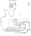
- FIGURE 1 is a cross-sectional, stylized view of a heart muscle 10, showing the use of a heated catheter 30 to continuously monitor cardiac output in accordance with the present invention.
- the heated catheter 30 is shown after it has been inserted intravascularly into a right atrium 12 and extending into a right ventricle 14.
- a balloon 18 is inflated to carry the distal end of the heated catheter into pulmonary artery 16.
- Disposed upon heated catheter 30 is a resistive heater 32, mounted so that it is set back from a distal end of heated catheter 30. As shown in the embodiment of FIGURE 1, the heater 32 is set back about 15 cm from the distal end of heated catheter 30.
- Resistive heater 32 preferably comprises a coiled wire of copper or other electrically conductive material, and is about 15 cm long in the preferred embodiment.
- Heated catheter 30 is connectable to a continuous cardiac output monitor 20 via a lead 15, which provides an electrical current to resistive heater 32.
- the heating current is usually made to vary between zero and some predetermined maximum value in a repetitive fashion.
- the conventional method of determining the volumetric flow rate of blood being pumped by heart muscle 10 is by monitoring the amount of power that is dissipated in resistive heater 32 and the corresponding temperature rise of the blood leaving the heart due to this added heat. The temperature rise varies inversely with flow rate.
- a distal temperature sensor 34 that is disposed at the distal end of heated catheter 30 determines the temperature rise of the blood in the pulmonary artery 16.
- Use of a repetitive or continuously varying heating power waveform rather than a fixed heating power allows the blood temperature rise due to heating to be discriminated from naturally occurring blood temperature fluctuations and drift.
- cardiac output monitor 20 can include a microprocessor (not shown) that is capable of computing cardiac output as a function of the temperature rise of the blood and the power dissipated in resistive heater 32.
- a microprocessor not shown
- the temperature of the resistive heater may become sufficiently high to damage red blood cells as blood within heart muscle 10 is heated, due to a low rate of flow of blood through the heart.
- the power dissipation of resistive heater 32 is set sufficiently low to avoid overheating blood cells during low rates of flow, the signal-to-noise ratio may be too low to accurately measure high rates of flow when the temperature signal becomes very small.
- the patient may be burned during the insertion procedure because the blood is not flowing past resistive heater 32 to cool it.
- the present invention controls the temperature of resistive heater 32 so as to prevent injury, while insuring an adequate signal is provided.
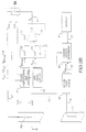
- FIGURES 2A and 2B are schematic block diagrams showing a first embodiment of means for sensing the temperature of resistive heater 32 on heated catheter 30.
- a temperature sensor 35 e.g., a thermistor
- temperature sensor 35 has a dash tag line to indicate that it is not required in several embodiments of this invention.
- Signal conditioning block 38 converts a signal from temperature sensor 35 to an output signal V Htemp , that is proportional to the temperature of resistive heater 32.
- a reference temperature block 43 provides a signal, V ref , that is proportional to a predetermined maximum temperature above which the temperature of resistive heater 32 should not rise.
- the signal V ref is preferably set to correspond to a reference temperature selected to avoid damage at the temperature and duration selected.
- Signal conditioning block 38 is connected to an inverting input terminal of a differential amplifier 40 via an input resistor 42, and reference temperature or set point block 43 is connected to a noninverting input terminal of differential amplifier 40 via an input resistor 44.
- a resistor 45a is connected between the noninverting input and ground, and a feedback resistor 45b is connected between the output and inverting input of differential amplifier 40.
- Current sensor 49 has a very low resistance so that a voltage drop across the heater (heater voltage), V htr , substantially equals V o .
- FIGURE 2B a second embodiment is illustrated that is the same as the first embodiment of FIGURE 2A, except that the voltage V o is applied through lead 47 to a constant current source 33.
- I o flows through current sensor 49 into heater 32 via lead 50.
- the heater voltage V htr in the embodiment of FIGURE 2A or current I o (in the embodiment of FIGURE 2B) falls causing less power to be dissipated in resistive heater 32, with a corresponding reduction in its temperature.
- the heater voltage V htr in the embodiment of FIGURE 2A or current I o (in the embodiment of FIGURE 2B) rises causing more power to be dissipated in resistive heater 31 with a corresponding increase in temperature.
- This feedback arrangement thus maintains the temperature of resistive heater 32 substantially at the predetermined temperature set by reference temperature block 43.
- current sensor 49 is connected to a power measurement block 52 and provides a signal over leads 55 and 57 proportional to the heater current I o .
- lead 57 also carries the heater voltage, V htr , as an input to the power measurement block.
- Power measurement block 52 determines the amount of power dissipated in resisitive heater 32 from the product of voltage drop across the heater, V htr , and the current through the heater, I o .
- a signal indicative of the power dissipated in resistive heater 32 is supplied from power measurement block 52 to a cardiac output determining block 54 via a lead 53.
- a lead 56 that extends through heated catheter 30 connects temperature sensor 34 to a distal temperature sensing block 59.
- Temperature sensing block 59 provides a signal indicative of the temperature rise of the blood downstream from resistive heater 32, due to heat from resistive heater 32, to cardiac output determination block 54 via a lead 58.
- cardiac output determination block 54 determines the volumetric rate of blood flow from heart muscle 10 for both the first and second embodiments.
- FIGURE 3A shows a third embodiment of the heated catheter system according to the present invention.
- a resistive heater 60 has a characteristic resistive temperature coefficient (RTC) that varies significantly in a well defined manner with temperature.
- Resistive heater 60 receives an electric current from a differential amplifier 70 via a lead 62.
- a current sensor 64 Connected in series between resistive heater 60 and the output of differential amplifier 70 is a current sensor 64, having a resistance, R s .
- a signal conditioning and processing block 66 determines the level of current flowing through the current sensor 64 and hence, through resistive heater 60.
- This heater current, I htr is determined from the ratio E s /R s .
- Signal conditioning and processing block 66 receives the voltage drop signal E s over leads 64a and 64b, and a signal indicative of the heater voltage, V htr , i.e., the voltage across resistive heater 60, via leads 64c and 64d, which are connected at opposite ends of resistive heater 60. Signal conditioning and processing block 66 then determines the temperature of resistive heater 60 as a function of its resistance, which is obtained from the ratio of V htr /I htr , as well as the power dissipated in the heater from the product, V htr x I htr .
- An output signal of signal conditioning and processing block 66, V Htemp is proportional to the temperature of resistive heater 60; this output signal is connected to an inverting input terminal of differential amplifier 70 via a resistor 72.
- a reference block 68 provides a signal, V ref , corresponding to a predetermined temperature at which resistive heater 60 is to be maintained.
- reference block 68 provides a signal, V ref , corresponding to a variable reference for controlling the power dissipated in resistive heater 60.
- reference block 68 is connected to a noninverting input terminal of differential amplifier 70 via a resistor 74.
- the output of differential amplifier 70 is connected to lead 62, which carries the electrical current that heats resistive heater 60.
- a feedback resistor 75 is connected between lead 62 and the inverting input of the differential amplifier.
- a resistor 77 connects the noninverting input of the differential amplifier to ground.
- the output signal of differential amplifier 70 is thus proportional to V ref -V Htemp .
- lead 81 connects the V Htemp signal from signal conditioning and processing block 66 to a power control block 80.
- Power control block automatically controls the signal V ref , as explained below.
- power control block 80 receives a signal on a lead 67 from signal conditioning and processing block 66 that is proportional to the power being dissipated by resistive heater 60.
- a generally constant power dissipation is maintained in resistive heater 60.
- power control block 80 compares the signal indicative of power dissipation in resistive heater 60 with a predefined setpoint power dissipation.
- Power control block 80 produces a control signal that is conveyed to reference block 68 over a lead 86 that adjusts the V ref signal so that the setpoint power dissipation is achieved and maintained.
- power control block 80 sends a control signal to reference block 68 over lead 86 that incrementally decreases the power dissipation being maintained in resistive heater 60, by adjusting the V ref signal. After a predefined time interval, e.g., 20 seconds, power control block 80 again adjusts the V ref signal to incrementally decrease the power dissipation in resistive heater 60 if its temperature still exceeds the predefined maximum value. Power control block 80 also incrementally increases the power dissipated in resistive heater 60 if its temperature drops below a predetermined minimum level. So long as the temperature of resistive heater 60 remains between the predetermined minimum and maximum levels, power control block 80 produces a control signal that maintains a constant power dissipation in the resistive heater.
- power control block 80 is not required (and is therefore omitted), and reference block 68 simply provides a V ref signal corresponding to the predetermined temperature at which resistive heater 60 is to be maintained. Differential amplifier 70 then produces an output current that varies so as to maintain the predetermined temperature.
- cardiac output determination block 82 is connected to receive the V Htemp signal over lead 67 and determines the cardiac output of the heart muscle based on the temperature of resistive heater 60, V Htemp , the power dissipated by it, and the temperature of the blood downstream, as described above.
- a display 84 is connected to cardiac determination block 82 by leads 83 to provide a visual indication of the cardiac output of the heart muscle.
- FIGURE 4 shows yet another embodiment of the present invention.
- a resistive heater 90 is chosen for its characteristic resistance that varies significantly with temperature.
- Resistive heater 90 comprises one arm of a bridge circuit 85 that also includes three fixed resistors 92, 94, and 96.
- Resistors 92 and 94 are connected in series at a node 93 to form the left side of the bridge circuit, while resistor 96 and resistive heater 90 are connected in a series at a node 95 to form the right side of the bridge circuit.
- Resistor 94 and resistive heater 90 are connected to ground at a node 98, while resistor 92 and resistor 96 are connected to a node 100 through which an electrical current is supplied to the bridge circuit.
- differential amplifier 110 Connected to the bridge circuit is a differential amplifier 110 having an inverting input terminal, which is connected to node 95 and a noninverting input terminal, which is connected to node 93.
- the output of differential amplifier 110 is connected to supply current to node 100 of the bridge circuit 85.
- resistive heater 90 When a resistive heater 90 with a positive temperature coefficient is used, if resistive heater 90 is initially cold and its resistance is relatively low; consequently, bridge circuit 85 is unbalanced, and the signal applied to the inverting input terminal of differential amplifier 110 is at a substantially different potential than the signal applied to its noninverting input terminal. Because the output signal of differential amplifier 110 is proportional to the difference between its inputs, the output signal causes an electrical current that is proportional to the differential input of differential amplifier 110 to flow through the bridge circuit. This electrical current causes resistive heater 90 to become warm.
- resistive heater 90 As the temperature of resistive heater 90 increases, its resistance rises until the voltage on bridge circuit output, node 95, which is applied to the inverting input of differential amplifier 110, rises to a level where it almost exactly matches the bridge output voltage applied to the noninverting input, at node 93, causing the differential amplifier output voltage to fall and reducing the heating current in resistive heater 90. If the voltage gain of differential amplifier 110 is high, the output voltage at node 100 settles to a value at which the heat dissipated in the resistive heater 90 just causes the bridge to balance with only a very small differential input to the differential amplifier 110. Any increased cooling of the resistive heater due to increased heat transfer to the blood causes the resistance of resistive heater 90 to decrease and changes the differential input voltage to differential amplifier 110.
- Power dissipation in resistive heater 90 is determined generally as explained above in respect to the embodiments of FIGURES 3A and 3B. Specifically, the voltage drop across resistor 96 is monitored between nodes 95 and 100, to determine the current, I htr , through resistive heater 90, and the voltage drop across the resistive heater, V htr , is determined between nodes 95 and 98 (ground). The power dissipated is thus simply the product of I htr and V htr .
Abstract
Description
- This invention generally pertains to a method and apparatus for controlling the temperature of a heated catheter, and more specifically, to controlling the temperature of a catheter used in determining cardiac output.
- Cardiac output, the volumetric rate at which blood is pumped through the heart, is most often determined clinically by injecting a bolus of chilled saline or glucose solution into the heart through a catheter. A thermistor inserted in the blood at a point downstream of the heart as the chilled injectate/blood mixture is pumped from the heart, is used to determine a temperature - time washout curve; the area under this curve provides an indication of cardiac output. Although this thermo-dilution method can give an indication of cardiac output at the time the procedure is performed, it cannot be used for continuously monitoring cardiac output. The frequency with which the procedure is performed is limited by its adverse effects on a patient, including the dilution of the patient's blood that occurs each time the chilled fluid is injected. In addition, the procedure poses an infection hazard to medical staff from blood contact, and to the patient from contaminated injectate fluid or syringes.
- An analogous method for measuring cardiac output involves the injection of a heated fluid into the heart; however, the same limitations on the frequency with which the measurement can be performed exist, whether the injectate is heated or chilled. Alternatively, blood in the heart can be chilled or heated by a heat transfer process using a temperature conditioned fluid that is circulated down one lumen within the catheter and returned back through another lumen. The principal advantages of using such a non-injectate heat transfer process to change the temperature of blood are that the blood is not diluted, and the temperature differential between the heat exchanger and the blood is reduced, compared to the differential temperature between an injectate fluid and blood in the typical thermal dilution method. U.S. Patent No. 4,819,655 discloses an injectateless method and apparatus for determining cardiac output in this fashion.
- Another technique for changing the temperature of blood circulating through the heart in order to determine cardiac output uses an electrical resistive heater that is disposed on the catheter and heated by an electrical current that is carded by conductors that run through one or more lumens in the catheter. A constant average power dissipation is typically maintained in the resistive heater, thereby enabling cardiac output to be determined as a simple function of the power dissipated and the temperature rise of blood measured downstream of the resistive heater. Several patents issued to H. Khalil, including U.S. Patent Nos. 3,359,974, 4,217,910, and 4,240,441, disclose various catheters and monitoring systems for carrying out this procedure.
- A disadvantage in maintaining a constant power dissipation in the resistive heater used in the preceding technique results from variations in the surface temperature of the heater as the rate of flow of blood past the heater changes. At relatively low rates of flow, the surface temperature of the catheter around the resistive heater can rise to a level at which damage to blood cells can occur. In addition, as the catheter is initially inserted into a patient's vascular system, care must be taken to turn off the electrical current used to heat the resistive hearer, since the absence of a cooling blood flow can cause the resistive heater to become hot enough to burn when it is outside the body. To avoid damaging the blood or burning the patient in this manner, the maximum power dissipated in the heating element is severely limited. The temperature increase in blood flowing past the resistive heater at higher rates of flow is thus minimal, and as a result, the temperature change of the blood measured downstream is relatively low. This condition produces a poor signal-to-noise ratio at high volumetric flow rates, since the signal indicating temperature rise of the blood downstream of the heating element varies as the reciprocal of blood flow rate.
- Previously Newbower (E. Trautman, R. Newbower, "The Development of Indicator Dilution Techniques", I.E.E.E. Trans. BME-31 No. 12 December 1984, pp. 800-807; R. Newbower et al., "Continuous Electronic Thermal Dilution Measurements," in Proc. 29th ACEMB, Boston, MA, 1976) concluded that within the safety constraints noted above, heated catheter based thermal dilution could not be used in most patients clinically, because of poor signal-to-noise ratio with the limited safe maximum power.
- Accordingly, it is an object of the present invention to provide a system for heating blood to determine cardiac output that avoids the limitations of prior art constant power dissipation systems, without creating a potential hazard of damaging blood cells by overheating or burning the patient. These and other objects and advantages of the present invention will be apparent by reference to the attached drawings and the Description of the Preferred Embodiments that follows.
- Apparatus comprising the present invention is used for heating blood flowing through a heart in order to determine cardiac output based upon a temperature rise of the blood. This apparatus includes a resistive heater that is connectable to a source of electrical current and is mounted on a catheter body that is adapted to be inserted intravascularly into the heart, the heater being mounted some distance from the catheter's distal end. Temperature sensing means are provided for sensing the temperature of the resisitive heater and for producing a signal indicative of that temperature. Control means are connected to receive the signal indicative of the temperature of the resistive heater and are operative to control the electrical current flowing from the source through the resistive heater so that the temperature of the resistive heater does not exceed a predetermined value.
- In one form of the invention, the temperature sensing means comprise a temperature sensor that is mounted in thermal communication with the resistive heater so as to sense its temperature. In another embodiment, a resistance of the resistive heater varies with its temperature, and the temperature sensing means include a plurality of resistors connected in a bridge circuit with the resistive heater. The control means operate to control the electrical current flowing through the resistive heater as a function of a potential developed across the bridge circuit.
- Alternatively, the temperature sensing means can comprise means for measuring the electrical current flowing through the resistive heater and a voltage drop across it. The signal indicative of the temperature of the resistive heater is then proportional to the ratio of the voltage drop and the electrical current flowing through the resistive heater (the resistive heater having a resistance that varies with temperature).
- In another form of the invention, the control means are operative to generally maintain a nominal, fixed power dissipation in the resistive heater, but reduce the electrical current flowing through the resistive heater to establish a different nominal fixed power dissipation if the temperature of the resistive heater otherwise exceeds the predetermined value. The control means can include means for producing a reference signal corresponding to the predetermined value and a comparator connected to compare the signal indicative of the temperature of the resistive heater to the reference signal to produce an output signal corresponding to their difference. The output signal of the control means is used to control the electrical current flowing through the resistive heater. In addition, the apparatus can include means for measuring the electrical power dissipated in the resistive heater as a function of the signal indicative of its temperature for use in determining the cardiac output.
- A method for protecting blood and tissue from damage due to overheating caused by heat transfer from a catheter used to monitor cardiac output comprises a further aspect of this invention. The method includes the steps of monitoring the temperature of a heated portion of the catheter and producing a signal indicative of that temperature. In response to the signal, the temperature of the heated portion is controlled to prevent it from exceeding a predetermined maximum safe level. The signal indicative of temperature is then used in determining power dissipated to heat the blood, which is used in determining cardiac output. The step of monitoring the temperature comprises the steps of measuring an electrical current flowing through a resistive heater and measuring a voltage drop across the resistive heater. The temperature of the heated potion of the catheter is then proportional to a ratio of the voltage drop and the electrical current. Alternatively, the step of monitoring the temperature comprises the step of monitoring a potential difference developed across the output from a bridge circuit in which the resistive heater is one part of the bridge circuit.
-
- FIGURE 1 is a cross-sectional stylized view of a heart muscle showing the use of a heated catheter to continuously monitor cardiac output in accordance with the present invention;
- FIGURE 2A is a schematic block diagram showing a first embodiment of means for sensing the temperature of a heated portion of the catheter and maintaining a constant temperature using a voltage source;
- FIGURE 2B is a schematic block diagram showing a second embodiment of the present invention, which is driven by a constant current source, but otherwise similar to the first embodiment of FIGURE 2A;
- FIGURE 3A is a schematic block diagram showing a third embodiment of means for sensing the temperature of the heated portion of the catheter:
- FIGURE 3B is a schematic block diagram showing a fourth embodiment, similar in many respects to the third embodiment of FIGURE 3A; and
- FIGURE 4 is a schematic block diagram showing a fifth embodiment of means for sensing the temperature of the heated portion of the catheter.
-
- FIGURE 1 is a cross-sectional, stylized view of a
heart muscle 10, showing the use of aheated catheter 30 to continuously monitor cardiac output in accordance with the present invention. Theheated catheter 30 is shown after it has been inserted intravascularly into aright atrium 12 and extending into aright ventricle 14. Aballoon 18 is inflated to carry the distal end of the heated catheter intopulmonary artery 16. Disposed upon heatedcatheter 30 is aresistive heater 32, mounted so that it is set back from a distal end of heatedcatheter 30. As shown in the embodiment of FIGURE 1, theheater 32 is set back about 15 cm from the distal end ofheated catheter 30.Resistive heater 32 preferably comprises a coiled wire of copper or other electrically conductive material, and is about 15 cm long in the preferred embodiment. Heatedcatheter 30 is connectable to a continuouscardiac output monitor 20 via alead 15, which provides an electrical current to resistiveheater 32. The heating current is usually made to vary between zero and some predetermined maximum value in a repetitive fashion. As blood flows intoright ventricle 14, its temperature is increased byresistive heater 32. Turbulence in the right ventricle ensures thorough mixing of the heated blood adjacent to the heated catheter, with the new blood entering the right ventricle before the heated blood is pumped out intopulmonary artery 16. The conventional method of determining the volumetric flow rate of blood being pumped byheart muscle 10 is by monitoring the amount of power that is dissipated inresistive heater 32 and the corresponding temperature rise of the blood leaving the heart due to this added heat. The temperature rise varies inversely with flow rate. Adistal temperature sensor 34 that is disposed at the distal end ofheated catheter 30 determines the temperature rise of the blood in thepulmonary artery 16. Use of a repetitive or continuously varying heating power waveform rather than a fixed heating power allows the blood temperature rise due to heating to be discriminated from naturally occurring blood temperature fluctuations and drift. - In the preferred embodiment, cardiac output monitor 20 can include a microprocessor (not shown) that is capable of computing cardiac output as a function of the temperature rise of the blood and the power dissipated in
resistive heater 32. As discussed above, when determining cardiac output using a heated catheter, the temperature of the resistive heater may become sufficiently high to damage red blood cells as blood withinheart muscle 10 is heated, due to a low rate of flow of blood through the heart. Conversely, if the power dissipation ofresistive heater 32 is set sufficiently low to avoid overheating blood cells during low rates of flow, the signal-to-noise ratio may be too low to accurately measure high rates of flow when the temperature signal becomes very small. Also, if electrical current is inadvertently applied toheated catheter 30 before it is inserted into the patient's vascular system, the patient may be burned during the insertion procedure because the blood is not flowing pastresistive heater 32 to cool it. The present invention controls the temperature ofresistive heater 32 so as to prevent injury, while insuring an adequate signal is provided. - FIGURES 2A and 2B are schematic block diagrams showing a first embodiment of means for sensing the temperature of
resistive heater 32 onheated catheter 30. A temperature sensor 35 (e.g., a thermistor) is disposed adjacentresistive heater 32 and is connected by a lead 36 to a temperature sensingsignal conditioning block 38. (In FIGURE 1,temperature sensor 35 has a dash tag line to indicate that it is not required in several embodiments of this invention.)Signal conditioning block 38 converts a signal fromtemperature sensor 35 to an output signal VHtemp, that is proportional to the temperature ofresistive heater 32. Areference temperature block 43 provides a signal, Vref, that is proportional to a predetermined maximum temperature above which the temperature ofresistive heater 32 should not rise. Blood is sensitive to elevated temperatures, and damage to red blood cells can occur even at relatively low temperatures if such temperature exposure is for a substantially long period of time. Accordingly, the signal Vref is preferably set to correspond to a reference temperature selected to avoid damage at the temperature and duration selected. -
Signal conditioning block 38 is connected to an inverting input terminal of adifferential amplifier 40 via aninput resistor 42, and reference temperature or setpoint block 43 is connected to a noninverting input terminal ofdifferential amplifier 40 via aninput resistor 44. Aresistor 45a is connected between the noninverting input and ground, and afeedback resistor 45b is connected between the output and inverting input ofdifferential amplifier 40.Differential amplifier 40 amplifies the difference between the signals VHtemp and Vref by a gain, K, to produce a voltage Vo, as follows:current sensor 49, and throughheater 32 via alead 50.Current sensor 49 has a very low resistance so that a voltage drop across the heater (heater voltage), Vhtr, substantially equals Vo. - In FIGURE 2B, a second embodiment is illustrated that is the same as the first embodiment of FIGURE 2A, except that the voltage Vo is applied through
lead 47 to a constantcurrent source 33. This voltage controls the constant current source so that it generates a constant current Io defined as follows:current sensor 49 intoheater 32 vialead 50. - If the heater temperature should rise above the level set by
reference temperature block 43, the heater voltage Vhtr (in the embodiment of FIGURE 2A) or current Io (in the embodiment of FIGURE 2B) falls causing less power to be dissipated inresistive heater 32, with a corresponding reduction in its temperature. Correspondingly, if the heater temperature should fall below the level set byreference temperature block 43, the heater voltage Vhtr (in the embodiment of FIGURE 2A) or current Io (in the embodiment of FIGURE 2B) rises causing more power to be dissipated in resistive heater 31 with a corresponding increase in temperature. This feedback arrangement thus maintains the temperature ofresistive heater 32 substantially at the predetermined temperature set byreference temperature block 43. - In both the first and the second embodiments,
current sensor 49 is connected to apower measurement block 52 and provides a signal over leads 55 and 57 proportional to the heater current Io. In addition, lead 57 also carries the heater voltage, Vhtr, as an input to the power measurement block.Power measurement block 52 determines the amount of power dissipated inresisitive heater 32 from the product of voltage drop across the heater, Vhtr, and the current through the heater, Io. A signal indicative of the power dissipated inresistive heater 32 is supplied frompower measurement block 52 to a cardiacoutput determining block 54 via alead 53. - A lead 56 that extends through
heated catheter 30 connectstemperature sensor 34 to a distaltemperature sensing block 59.Temperature sensing block 59 provides a signal indicative of the temperature rise of the blood downstream fromresistive heater 32, due to heat fromresistive heater 32, to cardiacoutput determination block 54 via alead 58. - Based an the signals indicative of the temperature rise of the blood provided via
lead 58 and the power dissipated inresistive heater 32 provided vialead 53, cardiacoutput determination block 54 determines the volumetric rate of blood flow fromheart muscle 10 for both the first and second embodiments. - FIGURE 3A shows a third embodiment of the heated catheter system according to the present invention. A
resistive heater 60 has a characteristic resistive temperature coefficient (RTC) that varies significantly in a well defined manner with temperature.Resistive heater 60 receives an electric current from adifferential amplifier 70 via alead 62. Connected in series betweenresistive heater 60 and the output ofdifferential amplifier 70 is acurrent sensor 64, having a resistance, Rs. By measuring a voltage drop, Es acrosscurrent sensor 64, a signal conditioning andprocessing block 66 determines the level of current flowing through thecurrent sensor 64 and hence, throughresistive heater 60. This heater current, Ihtr, is determined from the ratio Es/Rs. Signal conditioning andprocessing block 66 receives the voltage drop signal Es over leads 64a and 64b, and a signal indicative of the heater voltage, Vhtr, i.e., the voltage acrossresistive heater 60, vialeads 64c and 64d, which are connected at opposite ends ofresistive heater 60. Signal conditioning andprocessing block 66 then determines the temperature ofresistive heater 60 as a function of its resistance, which is obtained from the ratio of Vhtr/Ihtr, as well as the power dissipated in the heater from the product, Vhtr x Ihtr. - An output signal of signal conditioning and
processing block 66, VHtemp, is proportional to the temperature ofresistive heater 60; this output signal is connected to an inverting input terminal ofdifferential amplifier 70 via aresistor 72. Areference block 68 provides a signal, Vref, corresponding to a predetermined temperature at whichresistive heater 60 is to be maintained. In a fourth embodiment shown in FIGURE 3B,reference block 68 provides a signal, Vref, corresponding to a variable reference for controlling the power dissipated inresistive heater 60. In either case,reference block 68 is connected to a noninverting input terminal ofdifferential amplifier 70 via aresistor 74. The output ofdifferential amplifier 70 is connected to lead 62, which carries the electrical current that heatsresistive heater 60. Afeedback resistor 75 is connected betweenlead 62 and the inverting input of the differential amplifier. Aresistor 77 connects the noninverting input of the differential amplifier to ground. The output signal ofdifferential amplifier 70 is thus proportional to Vref-VHtemp. - Referring to the embodiment of FIGURE 3A, lead 81 connects the VHtemp signal from signal conditioning and
processing block 66 to apower control block 80. Power control block automatically controls the signal Vref, as explained below. - During use of the heated catheter,
power control block 80 receives a signal on a lead 67 from signal conditioning andprocessing block 66 that is proportional to the power being dissipated byresistive heater 60. In this embodiment of the invention (FIGURE 3A) a generally constant power dissipation is maintained inresistive heater 60. Accordingly,power control block 80 compares the signal indicative of power dissipation inresistive heater 60 with a predefined setpoint power dissipation.Power control block 80 produces a control signal that is conveyed toreference block 68 over a lead 86 that adjusts the Vref signal so that the setpoint power dissipation is achieved and maintained. However, should the temperature ofresistive heater 60 exceed a predefined maximum value,power control block 80 sends a control signal to referenceblock 68 overlead 86 that incrementally decreases the power dissipation being maintained inresistive heater 60, by adjusting the Vref signal. After a predefined time interval, e.g., 20 seconds,power control block 80 again adjusts the Vref signal to incrementally decrease the power dissipation inresistive heater 60 if its temperature still exceeds the predefined maximum value.Power control block 80 also incrementally increases the power dissipated inresistive heater 60 if its temperature drops below a predetermined minimum level. So long as the temperature ofresistive heater 60 remains between the predetermined minimum and maximum levels,power control block 80 produces a control signal that maintains a constant power dissipation in the resistive heater. - In the embodiment shown in FIGURE 3B,
power control block 80 is not required (and is therefore omitted), andreference block 68 simply provides a Vref signal corresponding to the predetermined temperature at whichresistive heater 60 is to be maintained.Differential amplifier 70 then produces an output current that varies so as to maintain the predetermined temperature. - For both of the embodiments of FIGURES 3A and 3B, cardiac
output determination block 82 is connected to receive the VHtemp signal overlead 67 and determines the cardiac output of the heart muscle based on the temperature ofresistive heater 60, VHtemp, the power dissipated by it, and the temperature of the blood downstream, as described above. Adisplay 84 is connected tocardiac determination block 82 byleads 83 to provide a visual indication of the cardiac output of the heart muscle. - FIGURE 4 shows yet another embodiment of the present invention. A
resistive heater 90 is chosen for its characteristic resistance that varies significantly with temperature.Resistive heater 90 comprises one arm of a bridge circuit 85 that also includes three fixedresistors Resistors node 93 to form the left side of the bridge circuit, whileresistor 96 andresistive heater 90 are connected in a series at anode 95 to form the right side of the bridge circuit.Resistor 94 andresistive heater 90 are connected to ground at a node 98, whileresistor 92 andresistor 96 are connected to anode 100 through which an electrical current is supplied to the bridge circuit. Connected to the bridge circuit is adifferential amplifier 110 having an inverting input terminal, which is connected tonode 95 and a noninverting input terminal, which is connected tonode 93. The output ofdifferential amplifier 110 is connected to supply current tonode 100 of the bridge circuit 85. - When a
resistive heater 90 with a positive temperature coefficient is used, ifresistive heater 90 is initially cold and its resistance is relatively low; consequently, bridge circuit 85 is unbalanced, and the signal applied to the inverting input terminal ofdifferential amplifier 110 is at a substantially different potential than the signal applied to its noninverting input terminal. Because the output signal ofdifferential amplifier 110 is proportional to the difference between its inputs, the output signal causes an electrical current that is proportional to the differential input ofdifferential amplifier 110 to flow through the bridge circuit. This electrical current causesresistive heater 90 to become warm. As the temperature ofresistive heater 90 increases, its resistance rises until the voltage on bridge circuit output,node 95, which is applied to the inverting input ofdifferential amplifier 110, rises to a level where it almost exactly matches the bridge output voltage applied to the noninverting input, atnode 93, causing the differential amplifier output voltage to fall and reducing the heating current inresistive heater 90. If the voltage gain ofdifferential amplifier 110 is high, the output voltage atnode 100 settles to a value at which the heat dissipated in theresistive heater 90 just causes the bridge to balance with only a very small differential input to thedifferential amplifier 110. Any increased cooling of the resistive heater due to increased heat transfer to the blood causes the resistance ofresistive heater 90 to decrease and changes the differential input voltage todifferential amplifier 110. This change in input voltage causes the differential amplifier output applied tonode 100 to rise, keeping the bridge balanced and the differential amplifier input low, by increasing power dissipation inresistive heater 90. Conversely, decreased cooling ofresistive heater 90 due to decreased heat transfer to the blood causes the heater resistance to fall and the amplifier output applied tonode 100 to fall, keeping the bridge balanced and the amplifier differential input low.Differential amplifier 110 and bridge circuit 85 thus cooperate to keepresistive heater 90 at the predetermined constant resistance and hence at a predetermined constant temperature determined by the resistance values selected forresistors resistive heater 90. - Power dissipation in
resistive heater 90 is determined generally as explained above in respect to the embodiments of FIGURES 3A and 3B. Specifically, the voltage drop acrossresistor 96 is monitored betweennodes resistive heater 90, and the voltage drop across the resistive heater, Vhtr, is determined betweennodes 95 and 98 (ground). The power dissipated is thus simply the product of Ihtr and Vhtr. - Although the preceding description has been directed to the preferred embodiments of the invention, those skilled in the art will realize that changes thereto can be made without departing from the spirit and scope of the invention as defined by the following claims. Therefore, the scope of the invention should be determined solely by reference to the claims.
Claims (5)
- A method for protecting blood and tissue from damage due to overheating caused by heat transfer from a catheter used to monitor cardiac output, comprising the steps of:providing a catheter (30) adapted for insertion into a heart;monitoring the temperature of a heated portion of the catheter (30) and producing a signal indicative thereof; andcontrolling the temperature of the heated portion of the catheter (30) in response to the signal indicative of the temperature of the heated portion of the catheter (30), to prevent the temperature of the heated portion of the catheter (30) from exceeding a level likely to damage the blood and tissue.
- The method of claim 1, wherein the step of monitoring the temperature comprises the steps of measuring an electrical current flowing through a resistive heater (32; 60; 90) used to provide heat, and measuring a voltage drop across the resistive heater (32; 60; 90), the temperature of the heated portion of the catheter (32) being proportional to a ratio of the voltage drop and the electrical current.
- The method of claim 1, wherein an electrical current flowing through a resistive heater (32; 60; 90) is used to provide the heat and wherein the step of monitoring the temperature comprises the step of monitoring a potential difference developed across a bridge circuit (90, 92, 94, 95) comprising the resistive heater (32; 60; 90).
- The method of claim 1 further comprising the steps:establishing a nominal fixed power dissipation for heating the blood;monitoring the temperature of the portion of the catheter (30) where heat is transferred to the blood and producing a signal indicative thereof; andin response to the signal, establishing a decreased nominal fixed power dissipation for heating the blood so that the temperature of the catheter (30) where heat is transferred to the blood is reduced to at least the level likely to avoid damage the blood and tissue.
- The method of claim 1 further comprising the step ofsensing the temperature of blood heated by the heated portion of the catheter (30) at a distance from the heated portion of the catheter (30) such that, when the heated portion of the catheter (30) is placed in the heart, the sensing step is performed in the pulmonary artery, the heated portion of the catheter (30) having a length sufficient to span over portions of the heart atrium and ventricle, anddetermining cardiac output based on the sensed heated blood temperature and on the power dissipated by the heated portion of the catheter (30).
Applications Claiming Priority (3)
| Application Number | Priority Date | Filing Date | Title |
|---|---|---|---|
| US07/717,549 US5277191A (en) | 1991-06-19 | 1991-06-19 | Heated catheter for monitoring cardiac output |
| US717549 | 1991-06-19 | ||
| EP92914564A EP0597881B2 (en) | 1991-06-19 | 1992-06-12 | Heated catheter for monitoring cardiac output |
Related Parent Applications (1)
| Application Number | Title | Priority Date | Filing Date |
|---|---|---|---|
| EP92914564A Division EP0597881B2 (en) | 1991-06-19 | 1992-06-12 | Heated catheter for monitoring cardiac output |
Publications (1)
| Publication Number | Publication Date |
|---|---|
| EP0962187A1 true EP0962187A1 (en) | 1999-12-08 |
Family
ID=24882473
Family Applications (2)
| Application Number | Title | Priority Date | Filing Date |
|---|---|---|---|
| EP92914564A Expired - Lifetime EP0597881B2 (en) | 1991-06-19 | 1992-06-12 | Heated catheter for monitoring cardiac output |
| EP99116854A Ceased EP0962187A1 (en) | 1991-06-19 | 1992-06-12 | Protecting blood and tissue from damage during monitoring of cardiac output |
Family Applications Before (1)
| Application Number | Title | Priority Date | Filing Date |
|---|---|---|---|
| EP92914564A Expired - Lifetime EP0597881B2 (en) | 1991-06-19 | 1992-06-12 | Heated catheter for monitoring cardiac output |
Country Status (11)
| Country | Link |
|---|---|
| US (2) | US5277191A (en) |
| EP (2) | EP0597881B2 (en) |
| JP (2) | JP3347728B2 (en) |
| AT (1) | ATE188362T1 (en) |
| AU (2) | AU668688B2 (en) |
| CA (1) | CA2110396C (en) |
| DE (1) | DE69230534T3 (en) |
| DK (1) | DK0597881T5 (en) |
| ES (1) | ES2143988T5 (en) |
| GR (1) | GR3032250T3 (en) |
| WO (1) | WO1992022240A1 (en) |
Families Citing this family (46)
| Publication number | Priority date | Publication date | Assignee | Title |
|---|---|---|---|---|
| US5720293A (en) * | 1991-01-29 | 1998-02-24 | Baxter International Inc. | Diagnostic catheter with memory |
| US6387052B1 (en) * | 1991-01-29 | 2002-05-14 | Edwards Lifesciences Corporation | Thermodilution catheter having a safe, flexible heating element |
| US5553622A (en) * | 1991-01-29 | 1996-09-10 | Mckown; Russell C. | System and method for controlling the temperature of a catheter-mounted heater |
| US5217019A (en) * | 1991-12-27 | 1993-06-08 | Abbott Laboratories | Apparatus and method for continuously monitoring cardiac output |
| US5435308A (en) * | 1992-07-16 | 1995-07-25 | Abbott Laboratories | Multi-purpose multi-parameter cardiac catheter |
| US6849083B2 (en) * | 1993-02-10 | 2005-02-01 | Radiant Medical, Inc. | Method and apparatus for controlling a patients's body temperature by in situ blood temperature modification |
| US6110168A (en) * | 1993-02-10 | 2000-08-29 | Radiant Medical, Inc. | Method and apparatus for controlling a patient's body temperature by in situ blood temperature modifications |
| US6620188B1 (en) * | 1998-08-24 | 2003-09-16 | Radiant Medical, Inc. | Methods and apparatus for regional and whole body temperature modification |
| US5837003A (en) * | 1993-02-10 | 1998-11-17 | Radiant Medical, Inc. | Method and apparatus for controlling a patient's body temperature by in situ blood temperature modification |
| US5346508A (en) * | 1993-04-29 | 1994-09-13 | Scimed Life Systems, Inc. | Apparatus and method for performing diagnostics and intravascular therapies |
| US5617870A (en) * | 1993-04-29 | 1997-04-08 | Scimed Life Systems, Inc. | Intravascular flow measurement system |
| US5636638A (en) * | 1994-06-29 | 1997-06-10 | Baxter International Inc. | Electrical power amplifier for continuous cardiac output monitoring |
| US5620002A (en) * | 1995-12-22 | 1997-04-15 | Abbott Critical Care Systems | Method for correcting thermal drift in cardiac output determination |
| AU768933B2 (en) * | 1996-01-08 | 2004-01-08 | Radiant Medical, Inc. | Method and apparatus for controlling body temperature |
| US6231516B1 (en) | 1997-10-14 | 2001-05-15 | Vacusense, Inc. | Endoluminal implant with therapeutic and diagnostic capability |
| US20030036746A1 (en) | 2001-08-16 | 2003-02-20 | Avi Penner | Devices for intrabody delivery of molecules and systems and methods utilizing same |
| US6986744B1 (en) * | 1999-02-02 | 2006-01-17 | Transonic Systems, Inc. | Method and apparatus for determining blood flow during a vascular corrective procedure |
| GB9920112D0 (en) * | 1999-08-26 | 1999-10-27 | Aortech Int Plc | Improvements relating to catheters (I) |
| US20030150464A1 (en) * | 1999-12-17 | 2003-08-14 | Casscells S. Ward | Inducing apoptosis of atrial myocytes to treat atrial fibrillation |
| US7024248B2 (en) * | 2000-10-16 | 2006-04-04 | Remon Medical Technologies Ltd | Systems and methods for communicating with implantable devices |
| AU2003234883A1 (en) * | 2002-04-05 | 2003-10-27 | H. Frederick Bowman | Thermal monitoring of tissue perfusion with recalibration. |
| US8271093B2 (en) | 2004-09-17 | 2012-09-18 | Cardiac Pacemakers, Inc. | Systems and methods for deriving relative physiologic measurements using a backend computing system |
| US7632235B1 (en) | 2004-11-22 | 2009-12-15 | Pacesetter, Inc. | System and method for measuring cardiac output via thermal dilution using an implantable medical device with an external ultrasound power delivery system |
| US7813808B1 (en) | 2004-11-24 | 2010-10-12 | Remon Medical Technologies Ltd | Implanted sensor system with optimized operational and sensing parameters |
| DE202006021213U1 (en) | 2005-07-21 | 2013-11-08 | Covidien Lp | Apparatus for treating a hollow anatomical structure |
| US7742815B2 (en) * | 2005-09-09 | 2010-06-22 | Cardiac Pacemakers, Inc. | Using implanted sensors for feedback control of implanted medical devices |
| US20070167866A1 (en) * | 2005-11-29 | 2007-07-19 | Lopez George A | Cardiac output measurement devices and methods |
| US7955268B2 (en) * | 2006-07-21 | 2011-06-07 | Cardiac Pacemakers, Inc. | Multiple sensor deployment |
| US20080077440A1 (en) * | 2006-09-26 | 2008-03-27 | Remon Medical Technologies, Ltd | Drug dispenser responsive to physiological parameters |
| WO2008129290A1 (en) * | 2007-04-23 | 2008-10-30 | Cambridge Mechatronics Limited | Control circuits for an sma actuator |
| US20080312553A1 (en) * | 2007-06-14 | 2008-12-18 | Timmons Michael J | Intracorporeal pressure measurement devices and methods |
| US8725260B2 (en) * | 2008-02-11 | 2014-05-13 | Cardiac Pacemakers, Inc | Methods of monitoring hemodynamic status for rhythm discrimination within the heart |
| US8369960B2 (en) * | 2008-02-12 | 2013-02-05 | Cardiac Pacemakers, Inc. | Systems and methods for controlling wireless signal transfers between ultrasound-enabled medical devices |
| JP5465252B2 (en) * | 2008-10-10 | 2014-04-09 | カーディアック ペースメイカーズ, インコーポレイテッド | System and method for determining cardiac output using pulmonary artery pressure measurements |
| WO2010059291A1 (en) | 2008-11-19 | 2010-05-27 | Cardiac Pacemakers, Inc. | Assessment of pulmonary vascular resistance via pulmonary artery pressure |
| US20100324378A1 (en) * | 2009-06-17 | 2010-12-23 | Tran Binh C | Physiologic signal monitoring using ultrasound signals from implanted devices |
| KR101853882B1 (en) * | 2011-01-10 | 2018-05-02 | 삼성전자주식회사 | Bio material test device and controlling method thereof |
| JP5845536B2 (en) * | 2011-08-26 | 2016-01-20 | 学校法人早稲田大学 | Puncture target organ temperature distribution estimation system, analysis device, and analysis device program |
| US9974477B2 (en) * | 2013-03-15 | 2018-05-22 | St. Jude Medical, Cardiology Division, Inc. | Quantification of renal denervation via alterations in renal blood flow pre/post ablation |
| AU2015242353B2 (en) | 2014-04-04 | 2020-01-23 | St. Jude Medical Systems Ab | Intravascular pressure and flow data diagnostic systems, devices, and methods |
| JP6674553B2 (en) * | 2015-10-19 | 2020-04-01 | アイシーユー・メディカル・インコーポレーテッド | Hemodynamic monitoring system with detachable display unit |
| WO2018226991A1 (en) | 2017-06-07 | 2018-12-13 | Shifamed Holdings, Llc | Intravascular fluid movement devices, systems, and methods of use |
| WO2019094963A1 (en) | 2017-11-13 | 2019-05-16 | Shifamed Holdings, Llc | Intravascular fluid movement devices, systems, and methods of use |
| EP3746149A4 (en) | 2018-02-01 | 2021-10-27 | Shifamed Holdings, LLC | Intravascular blood pumps and methods of use and manufacture |
| WO2021016372A1 (en) | 2019-07-22 | 2021-01-28 | Shifamed Holdings, Llc | Intravascular blood pumps with struts and methods of use and manufacture |
| WO2021062265A1 (en) | 2019-09-25 | 2021-04-01 | Shifamed Holdings, Llc | Intravascular blood pump systems and methods of use and control thereof |
Citations (8)
| Publication number | Priority date | Publication date | Assignee | Title |
|---|---|---|---|---|
| US3075515A (en) * | 1958-10-17 | 1963-01-29 | Albert M Richards | Blood flow meter |
| US3359974A (en) | 1963-10-07 | 1967-12-26 | Hassan H Khalil | Device for the thermal determination of cardiac volumetric performance |
| US4217910A (en) | 1978-10-10 | 1980-08-19 | The United States Of America As Represented By The Secretary Of The Navy | Internal jugular and left ventricular thermodilution catheter |
| US4236527A (en) * | 1978-10-20 | 1980-12-02 | Massachusetts General Hospital | Cardiac output detection by multiple frequency thermodilution |
| US4240441A (en) | 1978-10-10 | 1980-12-23 | The United States Of America As Represented By The Secretary Of The Navy | Carotid thermodilution catheter |
| EP0182363A2 (en) * | 1984-11-21 | 1986-05-28 | TERUMO KABUSHIKI KAISHA trading as TERUMO CORPORATION | Cardiac output measurement system |
| EP0235811A2 (en) * | 1986-03-07 | 1987-09-09 | TERUMO KABUSHIKI KAISHA trading as TERUMO CORPORATION | Catheters for measurement of cardiac output and blood flow velocity |
| US4819655A (en) | 1987-08-04 | 1989-04-11 | Webler William E | Injectateless thermal cardiac output determination method and apparatus |
Family Cites Families (20)
| Publication number | Priority date | Publication date | Assignee | Title |
|---|---|---|---|---|
| US3085431A (en) * | 1959-12-28 | 1963-04-16 | Gen Electric | Flow measuring apparatus |
| US3438253A (en) * | 1966-11-15 | 1969-04-15 | Frederick W Kuether | Thermal device for measuring direction and velocity of fluid flow |
| SU1108331A1 (en) * | 1981-02-13 | 1984-08-15 | Предприятие П/Я В-8495 | Thermal flowmeter |
| US4450719A (en) * | 1982-10-13 | 1984-05-29 | Hitachi, Ltd. | Air flow meter |
| US4537068A (en) * | 1983-03-10 | 1985-08-27 | Dwyer Instruments, Inc. | Thermal anemometer |
| US4672962A (en) * | 1983-09-28 | 1987-06-16 | Cordis Corporation | Plaque softening method |
| JPS60236025A (en) * | 1984-05-09 | 1985-11-22 | Nippon Soken Inc | Air flow rate sensor |
| US4679561A (en) * | 1985-05-20 | 1987-07-14 | The United States Of America As Represented By The United States Department Of Energy | Implantable apparatus for localized heating of tissue |
| US4869248A (en) * | 1987-04-17 | 1989-09-26 | Narula Onkar S | Method and apparatus for localized thermal ablation |
| JPS6446056U (en) * | 1987-09-17 | 1989-03-22 | ||
| US4860744A (en) * | 1987-11-02 | 1989-08-29 | Raj K. Anand | Thermoelectrically controlled heat medical catheter |
| US4907589A (en) * | 1988-04-29 | 1990-03-13 | Cosman Eric R | Automatic over-temperature control apparatus for a therapeutic heating device |
| US4955377A (en) * | 1988-10-28 | 1990-09-11 | Lennox Charles D | Device and method for heating tissue in a patient's body |
| US4966597A (en) * | 1988-11-04 | 1990-10-30 | Cosman Eric R | Thermometric cardiac tissue ablation electrode with ultra-sensitive temperature detection |
| US4979948A (en) * | 1989-04-13 | 1990-12-25 | Purdue Research Foundation | Method and apparatus for thermally destroying a layer of an organ |
| US5056526A (en) * | 1989-10-27 | 1991-10-15 | Khalil Hassan H | Device for global evaluation of the left ventricular ejection fraction by thermodilution |
| US5122137A (en) * | 1990-04-27 | 1992-06-16 | Boston Scientific Corporation | Temperature controlled rf coagulation |
| US5035514A (en) * | 1990-05-07 | 1991-07-30 | Thermal Technologies, Inc. | Thermal probe for measuring thermal properties of a flowing medium |
| GB9011259D0 (en) * | 1990-05-19 | 1990-07-11 | Nashef Samer A | Catheters |
| US5072612A (en) * | 1990-08-07 | 1991-12-17 | The Boeing Company | System for determining position of normal shock in supersonic flow |
-
1991
- 1991-06-19 US US07/717,549 patent/US5277191A/en not_active Expired - Fee Related
-
1992
- 1992-06-12 JP JP50107293A patent/JP3347728B2/en not_active Expired - Lifetime
- 1992-06-12 EP EP92914564A patent/EP0597881B2/en not_active Expired - Lifetime
- 1992-06-12 DK DK92914564T patent/DK0597881T5/en active
- 1992-06-12 WO PCT/US1992/005038 patent/WO1992022240A1/en active IP Right Grant
- 1992-06-12 AU AU22579/92A patent/AU668688B2/en not_active Expired
- 1992-06-12 EP EP99116854A patent/EP0962187A1/en not_active Ceased
- 1992-06-12 AT AT92914564T patent/ATE188362T1/en not_active IP Right Cessation
- 1992-06-12 ES ES92914564T patent/ES2143988T5/en not_active Expired - Lifetime
- 1992-06-12 DE DE69230534T patent/DE69230534T3/en not_active Expired - Lifetime
- 1992-06-12 CA CA002110396A patent/CA2110396C/en not_active Expired - Lifetime
-
1993
- 1993-10-08 US US08/134,182 patent/US5474080A/en not_active Expired - Fee Related
-
1996
- 1996-06-05 AU AU54767/96A patent/AU692095B2/en not_active Expired
-
1999
- 1999-10-18 JP JP29599599A patent/JP3234825B2/en not_active Expired - Lifetime
- 1999-12-22 GR GR990403338T patent/GR3032250T3/en unknown
Patent Citations (8)
| Publication number | Priority date | Publication date | Assignee | Title |
|---|---|---|---|---|
| US3075515A (en) * | 1958-10-17 | 1963-01-29 | Albert M Richards | Blood flow meter |
| US3359974A (en) | 1963-10-07 | 1967-12-26 | Hassan H Khalil | Device for the thermal determination of cardiac volumetric performance |
| US4217910A (en) | 1978-10-10 | 1980-08-19 | The United States Of America As Represented By The Secretary Of The Navy | Internal jugular and left ventricular thermodilution catheter |
| US4240441A (en) | 1978-10-10 | 1980-12-23 | The United States Of America As Represented By The Secretary Of The Navy | Carotid thermodilution catheter |
| US4236527A (en) * | 1978-10-20 | 1980-12-02 | Massachusetts General Hospital | Cardiac output detection by multiple frequency thermodilution |
| EP0182363A2 (en) * | 1984-11-21 | 1986-05-28 | TERUMO KABUSHIKI KAISHA trading as TERUMO CORPORATION | Cardiac output measurement system |
| EP0235811A2 (en) * | 1986-03-07 | 1987-09-09 | TERUMO KABUSHIKI KAISHA trading as TERUMO CORPORATION | Catheters for measurement of cardiac output and blood flow velocity |
| US4819655A (en) | 1987-08-04 | 1989-04-11 | Webler William E | Injectateless thermal cardiac output determination method and apparatus |
Also Published As
| Publication number | Publication date |
|---|---|
| DK0597881T5 (en) | 2003-04-14 |
| US5474080A (en) | 1995-12-12 |
| AU5476796A (en) | 1996-09-05 |
| DK0597881T3 (en) | 2000-04-17 |
| WO1992022240A1 (en) | 1992-12-23 |
| EP0597881B2 (en) | 2003-03-12 |
| EP0597881B1 (en) | 2000-01-05 |
| AU692095B2 (en) | 1998-05-28 |
| DE69230534T2 (en) | 2000-08-24 |
| AU668688B2 (en) | 1996-05-16 |
| JPH06511166A (en) | 1994-12-15 |
| AU2257992A (en) | 1993-01-12 |
| DE69230534D1 (en) | 2000-02-10 |
| JP2000083915A (en) | 2000-03-28 |
| US5277191A (en) | 1994-01-11 |
| CA2110396A1 (en) | 1992-12-23 |
| EP0597881A4 (en) | 1995-08-09 |
| ES2143988T3 (en) | 2000-06-01 |
| GR3032250T3 (en) | 2000-04-27 |
| CA2110396C (en) | 2004-03-02 |
| JP3347728B2 (en) | 2002-11-20 |
| JP3234825B2 (en) | 2001-12-04 |
| EP0597881A1 (en) | 1994-05-25 |
| ES2143988T5 (en) | 2003-11-16 |
| ATE188362T1 (en) | 2000-01-15 |
| DE69230534T3 (en) | 2003-10-02 |
Similar Documents
| Publication | Publication Date | Title |
|---|---|---|
| EP0597881B1 (en) | Heated catheter for monitoring cardiac output | |
| US5553622A (en) | System and method for controlling the temperature of a catheter-mounted heater | |
| US7753854B2 (en) | Blood flow monitor with arterial and venous sensors | |
| US6565516B2 (en) | Method and apparatus for measuring continuous blood flow at low power | |
| JP3131696B2 (en) | Apparatus and method for continuously monitoring cardiac output | |
| EP0368296B1 (en) | Cardiac output measurement method and system for the application of same | |
| US6355001B1 (en) | Thermodilution catheter method using a safe, flexible heating element | |
| US5509424A (en) | Continuous cardiac output monitoring system | |
| JPH0368690B2 (en) | ||
| EP0625884B1 (en) | System and method for controlling the temperature of a catheter-mounted heater | |
| JP2511153B2 (en) | Cardiac output measuring device | |
| CA2404534C (en) | System and method for controlling the temperature of a catheter-mounted heater | |
| JPH0761323B2 (en) | Cardiac output measuring device | |
| WO2004086976A1 (en) | Blood flow monitor with venous and arterial sensors |
Legal Events
| Date | Code | Title | Description |
|---|---|---|---|
| PUAI | Public reference made under article 153(3) epc to a published international application that has entered the european phase |
Free format text: ORIGINAL CODE: 0009012 |
|
| 17P | Request for examination filed |
Effective date: 19990903 |
|
| AC | Divisional application: reference to earlier application |
Ref document number: 597881 Country of ref document: EP |
|
| AK | Designated contracting states |
Kind code of ref document: A1 Designated state(s): AT BE CH DE DK ES FR GB GR IT LI LU NL SE |
|
| AKX | Designation fees paid |
Free format text: AT BE CH DE DK ES FR GB GR IT LI LU NL SE |
|
| 17Q | First examination report despatched |
Effective date: 20000929 |
|
| STAA | Information on the status of an ep patent application or granted ep patent |
Free format text: STATUS: THE APPLICATION HAS BEEN REFUSED |
|
| 18R | Application refused |
Effective date: 20011028 |