EP0963048A2 - Max-log-APP decoding and related turbo decoding - Google Patents
Max-log-APP decoding and related turbo decoding Download PDFInfo
- Publication number
- EP0963048A2 EP0963048A2 EP99304246A EP99304246A EP0963048A2 EP 0963048 A2 EP0963048 A2 EP 0963048A2 EP 99304246 A EP99304246 A EP 99304246A EP 99304246 A EP99304246 A EP 99304246A EP 0963048 A2 EP0963048 A2 EP 0963048A2
- Authority
- EP
- European Patent Office
- Prior art keywords
- decoding
- max
- sequence
- mlse
- log
- Prior art date
- Legal status (The legal status is an assumption and is not a legal conclusion. Google has not performed a legal analysis and makes no representation as to the accuracy of the status listed.)
- Withdrawn
Links
Images


Classifications
-
- H—ELECTRICITY
- H03—ELECTRONIC CIRCUITRY
- H03M—CODING; DECODING; CODE CONVERSION IN GENERAL
- H03M13/00—Coding, decoding or code conversion, for error detection or error correction; Coding theory basic assumptions; Coding bounds; Error probability evaluation methods; Channel models; Simulation or testing of codes
- H03M13/37—Decoding methods or techniques, not specific to the particular type of coding provided for in groups H03M13/03 - H03M13/35
- H03M13/39—Sequence estimation, i.e. using statistical methods for the reconstruction of the original codes
- H03M13/3905—Maximum a posteriori probability [MAP] decoding or approximations thereof based on trellis or lattice decoding, e.g. forward-backward algorithm, log-MAP decoding, max-log-MAP decoding
-
- H—ELECTRICITY
- H03—ELECTRONIC CIRCUITRY
- H03M—CODING; DECODING; CODE CONVERSION IN GENERAL
- H03M13/00—Coding, decoding or code conversion, for error detection or error correction; Coding theory basic assumptions; Coding bounds; Error probability evaluation methods; Channel models; Simulation or testing of codes
- H03M13/27—Coding, decoding or code conversion, for error detection or error correction; Coding theory basic assumptions; Coding bounds; Error probability evaluation methods; Channel models; Simulation or testing of codes using interleaving techniques
- H03M13/275—Interleaver wherein the permutation pattern is obtained using a congruential operation of the type y=ax+b modulo c
-
- H—ELECTRICITY
- H03—ELECTRONIC CIRCUITRY
- H03M—CODING; DECODING; CODE CONVERSION IN GENERAL
- H03M13/00—Coding, decoding or code conversion, for error detection or error correction; Coding theory basic assumptions; Coding bounds; Error probability evaluation methods; Channel models; Simulation or testing of codes
- H03M13/27—Coding, decoding or code conversion, for error detection or error correction; Coding theory basic assumptions; Coding bounds; Error probability evaluation methods; Channel models; Simulation or testing of codes using interleaving techniques
- H03M13/2771—Internal interleaver for turbo codes
-
- H—ELECTRICITY
- H03—ELECTRONIC CIRCUITRY
- H03M—CODING; DECODING; CODE CONVERSION IN GENERAL
- H03M13/00—Coding, decoding or code conversion, for error detection or error correction; Coding theory basic assumptions; Coding bounds; Error probability evaluation methods; Channel models; Simulation or testing of codes
- H03M13/29—Coding, decoding or code conversion, for error detection or error correction; Coding theory basic assumptions; Coding bounds; Error probability evaluation methods; Channel models; Simulation or testing of codes combining two or more codes or code structures, e.g. product codes, generalised product codes, concatenated codes, inner and outer codes
- H03M13/2957—Turbo codes and decoding
Definitions
- This invention relates to max-log-APP decoding and is particularly concerned with max-log-APP decoder systems and methods suited for Turbo and Turbo-like forward-error-correcting codes, by using iterative processing.
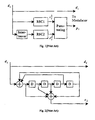
- the encoder consists of two rate 1/2 recursive systematic convolutional (RSC) encoders operating in parallel with the data binary digits (bits) interleaved between the two encoders as shown in Figure 1. Without puncturing, and with rate 1/2 constituent codes, the overall code rate is 1/3. This is because the systematic data bits only need to be sent once. Other code rates can be achieved as required by puncturing the purity bits c 1 i and c 2 i . In this configuration, the job of the interleaver is to spread reliability information that occurs in one code throughout the other code so that there is a higher probability of correcting unreliable informatin.
- FIG. 2 shows the RSC encoder, with polynomials (23,35) 8 , used in the prior art TURBO4 codec as discussed in B. Talibart and C. Berrou, "Notice Preliminaire du Circuit Turbo-C justify/Decodeur TURBO4", Version 0,0, June, 1995.
- This RSC encoder has four memory (delay) units.
- Soft-in/soft-out a posterior probability (APP) decoding of the systematic component codes is key to the decoding of Turbo-codes. This is also referred to as maximum a posteriori (MAP) decoding in the literature.
- MAP maximum a posteriori
- the so-called MAP algorithm was first derived by Bahl et al in their paper “Optimal Decoding of Linear Codes for Minimizing Symbol Error Rate", published in IEEE Trans. on Inform. Theory, Vol. IT-20, pp. 284-287, March 1974.
- the APP terminology is more correct in the context of soft-in/soft-out iterative processing, and this is the terminology used here.
- An APP decoder finds the probability of each data bit at each bit time given the entire received signal. Thus it also inherently provides the most likely bit value at each bit time given the entire received signal. This is in contrast to the well-known Viterbi algorithm, which performs maximum likelihood sequence estimation (MLSE) as discussed in A. Viterbi, "Error Bounds for Convolutional Codes and an Asymptotically optimum Decoding Algorithm", IEEE Trans. Inform. Theory, Vol. IT-13, pp. 260-269, April 1967; and G. Forney, "The Viterbi Algorithm”, Proc. IEEE, Vol. 61, No. 3, pp. 268-278, March 1973.
- MSE maximum likelihood sequence estimation
- the Viterbi algorithm finds the entire sequence that was most likely transmitted given the received signal. Both algorithms are optimum for their respective criteria, but the APP decoding approach more naturally provides the soft information required for iterative decoding. The relationship between these two decoding methods will be further explained below.
- the prior art APP decoding algorithm is now described.
- the data bit at time i is denoted as d i and is either 0 or 1.
- the state of the RSC encoder at time i is determined by the contents of the encoder's shift-register before d i enters the encoder.
- data bit d i causes the state of the encoder to change from S i to S i+l .
- the initial state S i is usually set to zero.
- S K +1 the final state
- S K +1 the last mem systematic bits are often reserved and specifically chosen to flush or terminate the encoder into the zero state, where mem is the memory of the RSC encoder.
- the usual approach with Turbo-codes is to terminate the first RSC code, interleave the data and flush bits, and then leave the second RSC code unterminated
- the outputs at time i are the systematic data bit d i and the coded parity bit c i . These outputs are typically modulated using an antipodal signaling scheme such as BPSK or QPSK and sent through an additive white Gaussian noise (AWGN) channel.
- AWGN additive white Gaussian noise
- R ), d 0, 1 is the a posteriori probability (APP) of the data bit d i .
- APP a posteriori probability
- the function f ( x ) can be easily implemented in a small single-parameter lookup table. It has been found that a table size of 16 or more, spanning an input range from 0 to 8, typically results in negligible degradation for Turbo decoding. By extension, the following operation is also defined:
- LLR's log likelihood ratios
- the order of operations for the log-APP algorithm is similar to that for the APP algorithm.
- the branch metrics are again given by (23) or (24).
- the factor of 1/2 could also be dropped in (30) if the max-log-APP decoding algorithm is only used once. When used iteratively in a Turbo decoder however, it is important that the output LLR's be scaled appropriately for reusing the parity channel samples, ⁇ y i ⁇ , which do not get improved or rescaled.
- a 's are calculated in the same way that a Viterbi algorithm calculates its state metrics, given all past channel samples.
- the B 's are also calculated using the metric portion of a Viterbi algorithm, but going backwards in time using all future samples.
- the max-log-APP algorithm finds the same MLSE sequence as the Viterbi algorithm (given sufficient history depth for all paths to merge). This has also already been noted in P. Robertson, P. Hoeher, and E. Villebrun, "Optimal and Sub-Optimal Maximum a Posteriori Algorithms Suitable for Turbo Decoding", IEEE Communications Theory, Vol. 8, No.
- the Viterbi algorithm does not need to keep track of state histories, but requires both forward and backward state metrics. That is, the max-log-APP algorithm does not require the history portion of a Viterbi algorithm. Another important difference is that the Viterbi algorithm does not output soft information about each decision. Although the max-log-APP algorithm does output soft information, it is still suboptimum compared to the information provided by the APP or log-APP algorithms.
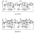
- Figure 3 shows a prior art approach to Turbo decoding based on the log-APP decoding algorithm.
- the Turbo decoder uses an iterative process where the de-interleaved output vector of the second log-APP decoder, L 2 , is fed back to the input of the first log-APP decoder after the first iteration.
- the first iteration uses the channel sample vector, X , corresponding to the Systematic bits. These samples must be scaled by the channel reliability factor, L c , if true log-APP decoding is to be performed.
- the channel sample vectors Y 1 and Y 2 corresponding to the parity bits from RSC encoders 1 and 2, are never updated and are used in every iteration. These channel samples must also be scaled by L c for true log-APP decoding.
- the extrinsic information vector, L ex associated with a particular log-APP decoder is defined as the output, L out , minus the input, L in .
- This extrinsic information is saved (delayed) and subtracted off the input to the same log-APP decoder on the next iteration. It is well known that this operation generally improves performance and speeds up the convergence of the Turbo decoder. On the first iteration there is no extrinsic information to be subtracted off, thus this operation can be avoided.
- the vector that is input to the second log-APP decoder must be interleaved using the same interleaver that was used in the Turbo-code-encoder. Likewise, the output from the second log-APP decoder must be de-interleaved before being fed back to the input of the first log-APP decoder. Decisions can be made either at the output of the first log-APP decoder or the de-interleaved output of the second log-APP decoder. It is convention that one Turbo decoding iteration be defined as two log-APP decoding operations as shown in Figure 3. To avoid confusion we will generally refer to the number of individual decoding operations, rather than the number of iterations.
- Figure 4 shows a modified Turbo decoder. This approach was briefly described in S. Crozier, A. Hunt, K. Gracie, and J. Lodge, "Performance and Complexity Comparison of Block Turbo-Codes, Hyper-Codes, and Tail-Biting Convolutional Codes", 19-th Biennial Symposium on Communications, Beverly, Ontario, Canada, pp.84-88, May 31-June 3, 1998 and is also described in a co-pending U.S. patent application 60/055,611 filed 14 August 1997. It is similar to the block diagram shown in Figure 3 for the standard approach to Turbo decoding. One important difference is the use of the lower-complexity max-log-APP decoder, instead of the log-APP decoder, as the component decoder.
- the max-log-APP decoder is insensitive to scale factors. Thus the systematic and parity channel sample vectors, X , Y 1 and Y 2 , no longer need to be scaled by the channel reliability factor, L c , and this factor no longer needs to be estimated. Another important difference is the correction of both the total output, L out , and the extrinsic information, L ex , generated by each max log-APP decoder.
- the best SF is a function of the signal-to-noise ratio (SNR), the block size, the puncture rate, and the Turbo decoder iteration number.
- SNR signal-to-noise ratio
- the degradation from true log-APP decoding is typically within 0.1 or 0.2 dB, depending on the operating point.
- the corrected extrinsic information is saved (delayed) and subtracted off the input to the same max-log-APP decoder on the next iteration.
- the input vector to the second max-log-APP decoder must be interleaved using the same interleaver used in the Turbo-code encoder.
- the corrected output from the second max-log-APP decoder must be de-interleaved before being fed back to the input of the first max-log-APP decoder.
- the first step is to define a state metric algorithm as a state metric portion of a Viterbi decoding method corresponding to said convolutional encoding methods
- the second step is to compute a set of N S forward state metrics, at each time i , using the state metric algorithm.
- the third step is to compute a set of N S backward state metrics, at each time i , using the state metric algorithm.
- the fourth step is to find a maximum metric M for an MLSE sequence corresponding to the received sequence.
- the fifth step is to define a combined metric for a bit value at time i as the sum of a forward state metric, a branch metric, and a backward state metric, corresponding to a branch of the encoding trellis for said bit value.
- the sixth step is to define max i (0) and max i (1) as the maximum of all combined metrics at time i for the data bit values of 0 and 1, respectively.
- the seventh, and last step is to compute at least one output LLR as L out ( i ) at time i , corresponding to the data bit at time i , as the difference between max i (0) and max i (1), using a method of metric combining where one of max i (0) and max i (1) is determined to have a value of M independent of the corresponding combined metrics.
- the first step is to define a state metric algorithm and a history algorithm as a state metric portion and a history portion respectively of a Viterbi decoding method corresponding to said convolutional encoding method.
- the second step is to compute a set of N S forward state metrics at each time i , using the state metric algorithm.
- the third step is to compute a set of N S backward state metrics at each time i , using the state metric algorithm.
- the fourth step is to find an MLSE sequence, corresponding to the received sequence of samples, using the history algorithm.
- the fifth step is to find a maximum metric M for the MLSE sequence.
- the sixth step is to define a combined metric for a bit value at time i as the sum of a forward state metric, a branch metric, and a backward state metric, corresponding to a branch of the encoding trellis for said bit value, at time i .
- the seventh step is to define max i (0) and max i (1) as the maximum of all combined metrics at time i for the data bit values of 0 and 1, respectively.
- the eighth step is to compute at least one output LLR as L out ( i ) at time i , corresponding to the data bit at time i , as the difference between max i (0) and max i (1), using a method of metric combining dependent on the i -th bit of the MLSE sequence, when one of max i (0) and max i (1) is determined to have a value of M independent of the corresponding combined metrics.
- a further embodiment of this invention provides a decoding method as above, wherein steps 2 and 3 are combined to implement a step of computing a set of forward state metrics and an MLSE sequence using said Viterbi decoding method with history.
- a further embodiment of this invention provides a decoding method as above, wherein steps 2 and 4 are combined to implement a step of computing a set of backward state metrics and an MLSE sequence using said Viterbi decoding with history.
- the first step is to define a state metric algorithm as a state metric portion of a Viterbi decoding method corresponding to said convolutional encoding method.
- the second step is to compute a set of N S forward state metrics, at each time i , using the state metric algorithm.
- the third step is to compute a set of N S backward state metrics, at each time i , using the state metric algorithm.
- the fourth step is to find an MLSE sequence, corresponding to the received sequence of samples, using one of the sets of forward and backward state metrics, and using a method of state metric retrace.
- the fifth step is to find a maximum metric M for the MLSE sequence.
- the sixth step is to define a combined metric for a bit value at time i as the sum of a forward state metric, a branch metric, and a backward state metric, corresponding to a branch of the encoding trellis for said bit value, at time i .
- the seventh step is to define max i (0) and max i (1) as the maximum of all combined metrics at time i for the data bit values of 0 and 1, respectively.
- the eighth step is to compute at least one output LLR as L out ( i ) , at some bit time i , corresponding to the data bit at time i , as the difference between max i (0) and max i (1), using a method of metric combining dependent on the i -th bit of the MLSE sequence, where one of max i (0) and max i (1) is determined to have a value of M independent of the corresponding combined metrics.
- Embodiments of the current invention allow all three prior aspects to be modified such that a decoding method as per the relevant aspect is described, wherein the convolutional encoding method uses systematic convolutional encoding.
- a further embodiment provides a method of decoding, wherein the convolutional encoding method uses recursive systematic convolutional (RSC) encoding.
- RSC recursive systematic convolutional
- a further embodiment provides a decoding method, wherein M is computed as the maximum of the last N S computed forward state metrics.
- a further embodiment is provides a decoding method wherein M is computed as the maximum of the last N S computed backward state metrics.
- a method of iterative decoding of a received sequence of samples representing a transmitted sequence of symbols obtained from encoding a data sequence of bits with a plurality of convolutional encoders comprising N dec decoding operations each corresponding to one of the convolutional encoders, where N dec is at least 2, wherein each of the first N dec -1 decoding operations uses a method of soft-in/soft-out decoding, to provide a soft input for the next decoding operation and the final N dec -th decoding operation uses a method of MLSE decoding to determine an MLSE sequence.
- Embodiments of the current invention provide an iterative decoding method as above, wherein at least one of the first N dec -1 decoding operations uses a method of either log-APP, or max-log-APP decoding.
- a further embodiment of the current invention is an iterative decoding method as above, wherein the final decoding operation uses a Viterbi decoding method with history to determine the MLSE sequence.
- a further embodiment of the current invention provides an iterative decoding method as above, wherein the final decoding operation uses a state metric portion of a Viterbi decoding method and a method of state metric retrace to determine the MLSE sequence.
- a further embodiment of the current invention provides an iterative decoding method as above, wherein the final decoding operation uses a method of max-log-APP decoding with an extrinsic information scale factor of one to determine the MLSE sequence.
- a method of iterative decoding of a received sequence of samples representing a transmitted sequence of symbols obtained from encoding a data sequence of bits with a plurality of convolutional encoders comprising N dec decoding operations each corresponding to one of the convolutional encoders, where N dec is at least 2, wherein each of the first N dec -1 decoding operations uses a method of soft-in/soft-out decoding, to provide a soft input for the next decoding operation, where at least one of the first N dec -1 decoding operations uses a method of max-log-APP decoding as in the first, second and third aspects of the current invention, and the final N dec -th decoding operation uses a method of MLSE decoding to determine an MLSE sequence.
- a method of iterative decoding of a received sequence of samples representing a transmitted sequence of symbols obtained from encoding a data sequence of bits with a plurality of systematic convolutional encoders said iterative decoding method including the following seven steps.
- the first step is to specify a maximum number D max of decoding operations, where D max is at least 2, and each decoding operation corresponds to one of the systematic convolutional encoders.
- the second step is to specify a minimum number D min of decoding operations, where D min is at least 1.
- the third step is to specify a preferred number D ag of consecutive agreements, between two consecutive MLSE sequences, where D ag is at least 1.
- the fourth step is to count the number of decoding operations performed as N dec .
- the fifth step is to test if N dec is equal to D max and stopping the iterative decoding method when true.
- the sixth step is to count the number of consecutive agreements, N ag , between two consecutive MLSE sequences.
- the seventh step is to test if N ag is equal to D ag and stopping the iterative decoder method when true.
- the second condition is that each decoding operation from D min -D ag to N dec -1 uses a first method of MLSE decoding to find an MLSE sequence.
- the third condition is that the final N dec -th decoding operation uses a second method of MLSE decoding to find a final MLSE Sequence.
- An embodiment of the current invention provides an iterative decoding method as above, wherein the soft-in/soft-out decoding method uses a method of log-APP decoding.
- a further embodiment of the current invention provides an iterative decoding method as above, wherein the soft-in/soft-out decoding method uses a method of max-log-APP decoding.
- a further embodiment of the current invention provides an iterative decoding method as above wherein the second method of MLSE decoding uses a Viterbi decoding method with history to determine the final MLSE sequence.
- a further embodiment of the current invention provides an iterative decoding method as above, wherein the second method of MLSE decoding uses a state metric portion of a Viterbi decoding method and a method of state mobic retrace to determine the final MLSE sequence.
- a further embodiment of the current invention provides an iterative decoding method as in claim 32 wherein the second method of MLSE decoding uses a method of max-log-APP decoding with an extrinsic information scale factor of one to determine the final MLSE sequence.
- a further embodiment of the current invention provides a method of repeated iterative decoding of a received sequence of samples representing a transmitted sequence of symbols obtained from encoding a data sequence of bits with a plurality of systematic convolutional encoders, by adding four steps to the process above.
- the first additional step is to perform a repetition of an iterative decoding method as above.
- the second additional step is to specify a maximum number of iterative decoding repetitions, I max , where I max is at least 1.
- the third additional step is to count the number of iterative decoding repetitions performed as N it .
- the fourth additional step is to perform a test if N dec is equal to D max and if N ag is less than D ag and if N it is less than I max , such that if the test is true, then a further repetition is performed wherein a sequence of decoding operations is different from a corresponding sequence of decoding operations used in all previous repetitions of iterative decoding.
- a method of iterative decoding of a received sequence of samples representing a transmitted sequence of symbols obtained from encoding a data sequence of bits with a plurality of convolutional encoders comprising N dec decoding operations each corresponding to one of the convolutional encoders, when N dec is at least 2, if the following conditions are fulfilled.
- the first condition is that N dec equals N 1 + N 2 , where N 1 a number of first decoding operations and is at least 1, and N 2 is a number of second decoding operations and is at lead 1.
- the second condition is that each of the N 1 first decoding operations uses a method of log-APP decoding.
- the third condition is that each of the N 2 second decoding operations uses a method of max-log-APP decoding.
- a method of iterative decoding of a received sequence of samples representing a transmitted sequence of symbols obtained from encoding a data sequence of bits with a plurality of convolutional encoders comprising N dec decoding operations each corresponding to one of the convolutional encoders, where N dec is at least 2, if the following conditions are fulfilled.
- the first condition is that N dec equals N 1 + N 2 +1, where N 1 a number of first decoding operations and is at least 1, N 2 is a number of second decoding operations and is at least 0, and there is a single third decoding operation.
- the second condition is that each of the N 1 first decoding operations uses a method of log-APP decoding.
- the third condition is that each of the N 2 second decoding operations uses a method of max-log-APP decoding.
- the fourth condition is that the single third decoding operation uses a method of MLSE decoding.
- Embodiments of the previous two aspects provide an iterative decoding method as in the above mentioned aspects, including a method of early stopping based on comparing consecutive MLSE sequences where each MLSE sequence corresponds to one of the decoding operations.
- Equation (33) defines L i , which is the LLR for the systematic bit at time i .
- Equation (34) defines max i (0), which is the maximum combined metric for all branches corresponding to a systematic bit value of 0 at time i .
- max i (0) is the metric associated with the MLSE sequence having a 0 at time i
- max i (1) is the metric associated with the MLSE sequence having a 1 at time i
- One of these two maximum combined metrics must be the metric associated with the actual unconstrained MLSE sequence, which is unique (assuming no ties).
- the other maximum combined metric must always be smaller.
- the max-log-APP algorithm always finds the same MLSE sequence, and corresponding metric, as the Viterbi algorithm (given sufficient history depth for all paths to merge, and apart from any constant metric offset due to metric normalization). This result is used in various embodiments of the present invention to reduce the number of computations required in (34) and (35), as described below.
- M the metric for the MLSE sequence.
- M is the maximum of the final N S forward state metrics computed at the end of the K input LLR's.
- the state metric for the known ending state is used.
- the approach described is further improved as follows.
- the algorithm can predict which bit value was more likely to be on the overall MLSE path at time i , and that the algorithm performs the combined metric processing for the opposite bit value first, then half the combined metric processing is eliminated every time this prediction is correct. This prediction is simply made by checking the sign of the input LLR corresponding to the systematic bit at each time i .
- the probability of an incorrect prediction is the probability of a raw channel bit error, which is typically less than 20% for most operating points of interest.
- Figures 5, 6, and 7 show how these two methods of combined metric processing are incorporated into a max-log-APP decoder, such as the max-log-APP decoders of Fig. 4 in accordance with this invention.
- Figure 5 illustrates, in a flow diagram, the common steps for these two methods of performing max-log-APP decoding.
- the inputs are the systematic channel sample vector X corresponding to the systematic bits and the parity channel sample vector Y corresponding to the parity bits of one or more convolutional encoders.
- the systematic vector could be a set of updated LLR's, L in , if the decoder is used as part of an iterative decoding process.
- the first step 10 is to compute the forward state metrics using the state metric portion of a Viterbi algorithm as in (27).
- the second step 12 is to find the maximum metric M for the MLSE sequence as in (36).
- the third step 14 is to compute the backward state metrics using the state metric portion of a Viterbi algorithm as in (28).
- the fourth step 16 is to compute the output LLR's, L o ut , one for each time i , L out ( i ), using one of the two methods of metric combining described next.
- Figure 6 shows the steps required in an embodiment for performing low-complexity metric combining shown in Fig. 5 based on guessing the bits of an MLSE sequence.
- the method shown inherently assumes that the MLSE bit at time i is always a 1-bit. This is arbitrary and a similar method applies if the MLSE bit is assumed to be a 0-bit.
- the first step 20 in to compute max i (0) as in (34).
- the second step 21 is to test if max i (0) is less than M . If yes, then step 24 is performed by computing the appropriate LLR value L out ( i ) as max i (0)- M .
- step 22 computes max i (1) as in (35) and step 23 computes the appropriate output LLR value L out ( i ) as M -max i (1). Finally step 25 is performed to simply output the correct LLR value.
- Figure 7 shows the steps required in another embodiment for performing low-complexity metric combining shown in Fig. 5 based on predicting the bits of an MLSE sequence.
- An input at time i is the i -th input LLR, L in ( i ). This value is used to predict the MLSE bit at time i .
- the first step 3 0 is to test if L in ( i ) is less than 0. If yes, then a 1-bit is most likely and the steps on the right side of Figure 7 are used. These steps, 20 through 24 , and their order are identical to those shown in Figure 6. If no, then the 0-bit is most likely and the steps 22 , 31 , 20 , 24 and 23 on the left side of Figure 7 are used.
- Step 31 is to test if max i (1) is less than M , and the remaining steps are as described above. These steps are symmetrical to the other steps 20-24 shown on the right side of Figure 7.
- step 35 is performed to simply output the correct LLR value.
- the metric combining embodiment of Fig. 6 as described above guesses the bits of the MLSE sequence.
- the other embodiment of Fig. 7 as described above predicts the bits of the MLSE sequence from the input LLR's with more reliability, but still uses guessing. In either embodiment, it is not necessary to separately generate the actual MLSE sequence to perform metric combining.
- the MLSE sequence can be determined, however, from the signs of the output LLR's, L out , after the combined metric processing is completed.
- a full Viterbi algorithm including the usual steps of history updating and decision making, is used when calculating the forward (or backward) state metrics.
- This provides the MLSE sequence directly before any backward state metrics, combined metrics, and output LLR'S are calculated.
- This embodiment ensures to eliminate half the combined metric processing because the MLSE bit value at each time i will always be known before the combined metrics are calculated.
- the processing for this embodiment is more deterministic because it is not dependent on guessing the correct MLSE bit value.
- This embodiment is particularly suited to those processors and/or algorithms where the history handling can be performed with relatively little overhead.
- iterative Turbo decoders can take advantage of the feature in that the MLSE sequence is determined prior to calculating the backward state metrics, combined metrics output LLR's.
- FIG 8 illustrates, in a flow diagram, this Viterbi history method of performing low-complexity max-log-APP decoding.
- the inputs are the same as in Figure 5.
- the first step 10 is to compute the forward state metrics using the state metric portion of a Viterbi algorithm as in (27).
- the second step 40 is to find the MLSE sequence using the history portion of a Viterbi algorithm. Step 10 and 40 are preferably executed together as a full Viterbi algorithm.
- the third step 12 is to find maximum metric M for the MLSE sequence as in (36).
- the fourth step 14 is to compute the backward state metrics using the state metric portion of a Viterbi algorithm as in (28).
- the fifth step 42 is to compute the output LLR's, L out , one for each time i , L out ( i ) , using the method of metric combining described below and shown in Figure 9.
- Figure 9 illustrates, in a flow diagram, an embodiment performing low-complexity metric combining based on knowing the bits of an MLSE sequence.
- An input at time i is the i -th bit of the MLSE sequence, referred to as the i -th MLSE bit, bit i .
- the first step 50 is to test if bit i equals 1. If yes then steps 20 and 24 are used, as described before and shown on the right of Fig. 9. If no then steps 22 and 23 are used, as shown on the left, and as described before. Finally, step 55 is to simply output the correct LLR value.
- the MLSE sequence can be determined in another way, without the history processing usually associated with a full Viterbi decoder.
- Conventional Viterbi decoders typically only store anew set of N S state metrics and an old set of N S state metrics. The new set is updated from the old set and then the new set becomes the old set for the next bit time. This saves memory. This is also why history processing is required for each state.
- a max-log-APP decoder as used in this embodiment is required to store the entire set of forward (or backward) state metrics for the entire data block (or subblock if overlapped sub-block processing is used).
- the MLSE sequence is easily determined by finding the most likely ending state, with state metric M , and retracing through the trellis from the most likely endling state using the stored state metrics and branch metrics.
- the winning previous state is the one that gives the winning current state metric when the previous state metric and associated branch metric are combined. This is expressed more rigorously as follows.
- bit i and b( bit i ,m ) are the winning bit and state values, respectively, at time i .
- This state metric retrace approach of determining the MLSE sequence is very efficient because the processing is not a function of the number of states. Only a single winning state needs to be considered at each step of the retrace process.
- the MLSE sequence can be determined prior to calculating the backward state metrics, combined metrics, and output LLR's, thereby saving approximately 50% of the combined metric processing.
- the MLSE sequence is determined at the same time as the backward state metrics, combined metrics, and LLR's are calculated, on a bit-by-bit basis, in order to save reading the forward state metrics and branch metrics from memory multiple times, and reuse some intermediate calculations.
- this approach is not as well suited to the iterative Turbo decoding embodiments described further below.
- Figure 10 illustrates, in a flow diagram, this embodiment performing low-complexity max-log-APP decoding using the state metric retrace method.
- the inputs are the same as in Figure 5.
- the first step 10 is to compute the forward state metrics using the state metric portion of a Viterbi algorithm as in (27),
- the second step 60 is to find maximum metric M for the MLSE sequence as in (36), and to find the corresponding most likely ending state. Of course, if the ending state is known then this state and its metre are used
- the third step 62 is to find the MLSE sequence using a state metric retrace approach, using the forward metrics, as indicated in (37).
- the fourth step 14 is to compute the backward state metrics using the state metric portion of a Viterbi algorithm as in (28).
- the fifth step 42 is to compute the output LLR's, L out , one for each time i , L out ( i ) , using the method of metric combining shown in Figure 9, as described previously,
- MLSE sequence in the context of iterative decoding does not necessarily mean a true maximum likelihood sequence, but it is rather loosely used to refer to a sequence generated by a decoder derived from maximum likelihood sequence estimation (MLSE) principles.
- MLSE maximum likelihood sequence estimation
- the modified Turbo decoder uses iterative max-log-APP processing with scaled extrinsic information, as indicated in (31) and (32).
- the best scale factor is usually less than 1.
- a scale factor of 1 is best for the final step of max-log-APP processing, especially when trying to minimize packet error rate.
- a max-log-APP decoder when used with an extrinsic information scale factor of 1, provides the same final decisions as an MLSE decoder.
- the final step of log-APP or max-log-APP decoding can be replaced with a simpler step of MLSE decoding.
- the last two approaches to reduced-complexity max-log-MP decoding shown in Figures 8 and 10 respectively, compute an MLSE sequence as an intermediate step.
- the last decoding step can stop after the MLSE sequence is determined. This eliminates all the processing associated with computing the backward state metrics, the combined metrics, and the LLR's, for the last decoding step.
- a simple early stopping technique that we found to work well, especially in combination with the other methods described above, is to compare the MLSE sequences associated with each log-APP or max-log-APP decoding operation to see if the MLSE sequences are changing with time.
- the robustness of this approach is specified by setting a desired number of consecutive agreements between two consecutive MLSE sequences, D ag . It has been found experimentally that very little degradation (typically only a few hundredths of a dB, and only at high SNRs) occur by requiring only one agreement between two consecutive MLSE sequences before stopping.
- This early stopping technique is not only effective but it requires little additional processing when used with the last two methods of max-log-APP decoding described above. The reason is because these methods of max-log-APP decoding compute an MLSE sequence as an intermediate step, to save processing, and thus each MLSE sequence is essentially available for free (except for storage). Further, the remaining processing of calculating the backward state metrics, the combined metrics, and the output LLR's can also be avoided for the last decoding operation, when the early stopping criterion is satisfied.
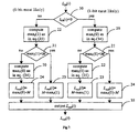
- Figure 11 illustrates, in a flow diagram, a Turbo decoding embodiment including a method of early stopping based on comparing consecutive MLSE sequences as discussed above.
- the first step 70 is to initialize the number of consecutive agreements, N ag , between two consecutive MLSE sequences, and to initialize the number of decoding operations perfonned, N dec .
- the inputs to the current decoding process are the appropriate LLR's ( X or L n ) and parity channel sample vector Y n , where n distinguishes the different RSC encodings performed in the Turbo-code encoder.
- One pass through Figure 11 represents one decoding operation, corresponding to one of the RSC encodings performed in the Turbo-code encoder.
- the second step 72 is to subtract the old extrinsic information stored for this decoding operation from the input LLR's. This step can be skipped if the old extrinsic information is all zeros, as for the first few decoding operations.
- the third step 10 is to compute the forward state metrics using the state metric portion of a Viterbi algorithm as in (27).
- the fourth step 60 is to find maximum metric M for the current MLSE Sequence as in (36), and to find the corresponding most likely ending state.
- the fifth step 62 is to find the current MLSE sequence using a state metric retrace approach, using the forward metrics, as indicated in (37).
- the sixth step 74 is to increment the number of decoding operations performed.
- the seventh step 82 is to test if the number of decoding operations performed equals the maximum number of decoding operations allowed, D max . If yes, then the final step 86 outputs the final MLSE sequence, de-interleaving if appropriate. If no, then an eighth step 84 is performed, which first tests to see if the minimum number of decoding operations. D min , has been performed. If yes, then the current and previous MLSE sequences are compared. If they agree, then the number of agreements, N ag , is incremented. If they do not agree, then N ag is reset to 0. The ninth step 80 is then to test if the number of agreements equals the desired number of agreements, D ag .
- the final step 86 outputs the final MLSE sequence, de-interleaving if appropriate. If no, then a tenth step 14 is performed, which computes the backward state metrics using the state metric portion of a Viterbi algorithm as in (28). The eleventh step 42 is then to compute the output LLR's, L out , one for each time i , L out ( i ), using the method of metric combining shown in Figure 9, as described previously. The twelfth step 76 is to compute the corrected output LLR's and corrected extrinsic information using an extrinsic information scale factor as in (31) and (32). The last step 78 , before returning to the second step 72 , is to interleave or de-interleave the corrected output LLR's, as appropriate, for the next decoding operation.
- a key to the success of the MLSE-based early stopping technique is the fact that MLSE sequences are being compared. It is also important that the final decision sequence be the last MLSE sequence obtained, or one of the last D ag +1 MLSE sequence, since they are the same when the early stopping test is satisfied.
- Several other simple early stopping techniques have been tried and they do not work as well. For example, it has been found that comparing the signs of consecutive LLR sequences does not work well, especially at high SNRs. This is true for both log-APP decoding, and max-jog-APP decoding with an extrinsic information scale factor less than one.
- the early stopping technique is used to improve performance in another way, wherein, the early stopping technique is used to detect a situation where the Turbo decoder fails to converge to a stable solution. This is achieved by noting when the maximum number of log-APP or max-log-APP decoding operations, D max , has been reached without the stopping criterion being satisfied.
- the Turbo decoder is given a second chance by perturbing the inputs or changing the startup conditions.
- the Turbo decoding process is started again using the second set of parity first. Even though the amount of processing is significantly increased for those cases where a second Turbo decoding is performed, with the early stopping technique the average amount of processing is only increased slightly at most operating points of interest.
- the log-APP decoding algorithm can be implemented using the same max operations as the max-log-APP decoding algorithm, but with an additional correction term that can be looked up in a table. Even through the table lookup approach sounds simple, the required processing is typically about 3 times that of the max-log-APP approaches described above, when implemented on a general purpose DSP. Although the improvement in performance is typically only 0.1 to 0.2 dB, it is still worthwhile for some applications.
- An effective hybrid embodiment for performing Turbo decoding is to use a log-APP decoding algorithm for the first few decoding operations followed by a max-log-APP decoding algorithm, with scaled extrinsic information, for the remaining decoding operations.
- the early stopping technique is turned on when switching to the max-log-APP decoding algorithm.
- performance and complexity There is an obvious tradeoff between performance and complexity. However, most of the gains in performance are obtained with only a few log-APP decoding operations.
- the systematic and parity channel sample vectors, X , Y 1 and Y 2 need to be scaled by the channel reliability factor, L c , and this factor needs to be estimated, in order to use the log-APP decoding algorithm for the first few decoding operations.
- a number of embodiments for Turbo-code encoders and associated iterative Turbo decoders have been implemented on several general purpose DSP platforms.
- the associated Turbo-code encoder uses two 16-state, memory-4, RSC component encoders operating in parallel, as shown in Figure 2.
- the following decoder throughput rates, in data kilobits per second (kbps), have been achieved with the modified Turbo decoder using 8 fixed max-log-APP decoding operations.
- the throughput for an Analog Devices 16-bit fixed-point ADSP-2181 processor running at 40 MIPS is about 17 kbps.
- a 40 MIPS Analog Devices SHARC processor has achieved a throughput of about 48 kbps.
- a 400 MHz Pentium-U processor with MMX has achieved over 400 kbps. With the early stopping technique the average throughput for the Pentium II easily exceeds 600 kbps, for most operating points of interest, while achieving the same performance as using 32 fixed max-log-APP decoding operations.
Abstract
Description
- This invention relates to max-log-APP decoding and is particularly concerned with max-log-APP decoder systems and methods suited for Turbo and Turbo-like forward-error-correcting codes, by using iterative processing.
- Claude Berrou obtained US patent 4,446,747 entitled: "Error-correction coding method with at least two systematic convolutional codings in parallel, corresponding iterative decoding method, decoding module and decoder", This patent describes essentially the same Turbo-code presented by Berrou et al in their paper "Near Shannon Limit Error-Correcting Coding and Decoding: Turbo-Codes", published in the Proceedings of ICC'93, Geneva, Switzerland, pp. 1064-1070, May, 1993. The Turbo-code presented, is a
rate 1/2 binary code that provided performance within 0.5 dB of the BPSK capacity limit at a BER of 10-5, when using an interleaver block size of 65,536. This result is also only 0.7 dB from the more general Shannon capacity limit. The encoder consists of tworate 1/2 recursive systematic convolutional (RSC) encoders operating in parallel with the data binary digits (bits) interleaved between the two encoders as shown in Figure 1. Without puncturing, and withrate 1/2 constituent codes, the overall code rate is 1/3. This is because the systematic data bits only need to be sent once. Other code rates can be achieved as required by puncturing the purity bits c 1 i and c 2 i . In this configuration, the job of the interleaver is to spread reliability information that occurs in one code throughout the other code so that there is a higher probability of correcting unreliable informatin. Figure 2 shows the RSC encoder, with polynomials (23,35)8, used in the prior art TURBO4 codec as discussed in B. Talibart and C. Berrou, "Notice Preliminaire du Circuit Turbo-Codeur/Decodeur TURBO4",Version - More recently Berrou, and Glavieux provided more discussion of the coding and decoding of Turbo-codes in their paper "Near Optimum Error Correcting Coding and Decoding: Turbo-Codes", published in the IEEE Trans. on Comm., Vol. 44, No. 10, October 1996.
- Soft-in/soft-out a posterior probability (APP) decoding of the systematic component codes is key to the decoding of Turbo-codes. This is also referred to as maximum a posteriori (MAP) decoding in the literature. The so-called MAP algorithm was first derived by Bahl et al in their paper "Optimal Decoding of Linear Codes for Minimizing Symbol Error Rate", published in IEEE Trans. on Inform. Theory, Vol. IT-20, pp. 284-287, March 1974. The APP terminology is more correct in the context of soft-in/soft-out iterative processing, and this is the terminology used here.
- An APP decoder finds the probability of each data bit at each bit time given the entire received signal. Thus it also inherently provides the most likely bit value at each bit time given the entire received signal. This is in contrast to the well-known Viterbi algorithm, which performs maximum likelihood sequence estimation (MLSE) as discussed in A. Viterbi, "Error Bounds for Convolutional Codes and an Asymptotically optimum Decoding Algorithm", IEEE Trans. Inform. Theory, Vol. IT-13, pp. 260-269, April 1967; and G. Forney, "The Viterbi Algorithm", Proc. IEEE, Vol. 61, No. 3, pp. 268-278, March 1973. That is, the Viterbi algorithm finds the entire sequence that was most likely transmitted given the received signal. Both algorithms are optimum for their respective criteria, but the APP decoding approach more naturally provides the soft information required for iterative decoding. The relationship between these two decoding methods will be further explained below.
- The following is a brief summary of the relevant background material required for understanding the invention, the APP, log-APP, and max-log-APP decoding algorithms are described. A more detailed description of these prior art algorithms is provided in, for example, L. Bald, J. Cocke, F. Jelinek, and J. Raviv, "Optimal Decoding of Linear Codes for Minimizing Symbol Error Rate", IEEE Trans. on Inform Theory, Vol. IT-20, pp. 284-287, March 1974; P. Robertson, E. Villebrun, and P. Hoeher, "A Comparison of Optimal and Sub-Optimal MAP Decoding Algorithms Operating in the Log Domain", Proceedings of ICC'95, Seattle, pp. 1009-1013, June 1995; P. Robertson, P. Hoeher, and E, Villebrun "Optimal and Sub-Optimal Maximum a Posteriori Algorithms Suitable for Turbo Decoding", IEEE Communications Therory, Vol. 8, No. 2, pp. 119-125, March-April 1997. S. Pietrobon, "Implementation and Performance of a Turbo/MAP Decoder", submitted to the International Journal of Satellite Communications, February 21 1997; J. Hatgenauer, E. Offer, and L. Papke, "Iterative Decoding of Binary Block and Convolutional Codes", IEEE Trans. on Inform Theory, Vol. 42, No. 2, pp. 429-445, March 1996; J. Erfanian, S. Pasupathy, G. Gulak, "Reduced Complexity Symbol Detectors with Parallel Structures for ISI Channels", IEEE Trans. on Communications, Vol. 42, No. 2/3/4, pp.1661-1671. February/March/April 1994.
- The decoding algorithms are presented in the context of systematic binary convolutional codes and an additive white Gaussian noise (AWGN) channel model. Of course this does not prevent their use in other systems with more complicated signaling constellations and channels. In the case of Turbo-codes, recursive systematic convolutional (RSC) codes are conventionally employed.
- The prior art APP decoding algorithm is now described. The data bit at time i is denoted as di and is either 0 or 1. The state of the RSC encoder at time i is determined by the contents of the encoder's shift-register before di enters the encoder. Thus, data bit di causes the state of the encoder to change from Si to Si+l. The initial state Si is usually set to zero. Here it is assumed that after K systematic bits the final state, S K +1, is also zero. In the case of RSC codes the last mem systematic bits are often reserved and specifically chosen to flush or terminate the encoder into the zero state, where mem is the memory of the RSC encoder. The number of states is NS =2 mem . The usual approach with Turbo-codes is to terminate the first RSC code, interleave the data and flush bits, and then leave the second RSC code unterminated
- Assuming a
rate 1/2 RSC encoder, as shown in Figure 2 for example, the outputs at time i are the systematic data bit di and the coded parity bit ci . These outputs are typically modulated using an antipodal signaling scheme such as BPSK or QPSK and sent through an additive white Gaussian noise (AWGN) channel. The received sequence is defined asy where Pr(di =d|R), d=0, 1 is the a posteriori probability (APP) of the data bit di . Once λ i is evaluated, decisions can be made as follows The efficient method of calculating λ i can be summarized as follows :
 where m is the state number and the summations are over all NS states. The α's and β's are the forward and backward state metrics, respectively, and the δ's are the branch metrics. The notation f(d,m) refers to the next forward state given input data bit d and current state m. Similarly, the notation h(d,m) refers to the next backward state given input d. The forward state metrics are updated recursively using
 The backward state metrics are updated recursively using

- Given the assumed signal and channel model, and assuming no a priori information about the bits (a priori information can easily be incorporated if desired), the branch metrics are given byor,
 where Ki and K'i are constants independent of the data and coded bits, Lc=2/σ 2 =4ES/N 0 is called the reliability value of the channel, and cd,m is the coded bit given input bit d with the encoder in state m. Recall that d' and c' are the corresponding ±1 transmission symbols as defined in (2) and (3). Constants Ki and K'i can be ignored or used to normalize the state metrics since they cancel in (6).
- Substituting (9) or (10) into (6) givesis the extrinsic information factor, used to correct the original systematic information to minimize the probability of decoding error.

- The APP decoding algorithm is implemented by first calculating the α's in the forward direction and storing the results. The β's are then calculated in the reverse direction. The λ's can be calculated at the same time as the β's to reduce the memory requirement, for the β's and to reduce the number of operations required for the λ's by reusing intermediate β calculations. It is clear from (6) and (8) what products can be reused. If the encoder starts in the zero state then we initialize
α 0 / 1 = 1 and α m / 1 = 0 for m≠0. If the encoder ends in the zero state then we initializeβ 0 / K+1 = 1 and β m / K+1 = 0 for m≠0. If the encoder ends in an unknown state then it is appropriate to initialize all β's to 1, or some other non-zero value. - The log-APP decoding algorithm is now described. Converting to the log domain we define
- The following operation can also be defined, using the well-known Jacobi's logarithm function, as described in P. Robertson, E. Villebrun, and P. Hoeher, "A Comparison of Optimal and Sub-Optimal MAP Decoding Algorithms Operating in the Log Domain", Proceedings of ICC'95, Seattle, pp. 1009-1013, June 1995; P. Robertson, P. Hoeher, and E. Villebrum, "Optimal and Sub-Optimal Maximum a Posteriori Algorithms Suitable for Turbo Decoding", IEEE Communications Theory, Vol. 8, No. 2, pp. 119-125, March-April 1997; S. Pietrobon, "Implementation and Performance of a Turbo/MAP Decoder", submitted to the International Journal of Satellite Communications, February 21 1997; J. Hagenauer, E. Offer, and L. Papke, "Iterative Decoding of Binary Block and Convolutional Codes", IEEE Trans. on Inform Theory, Vol. 42, No. 2, pp. 429-445, March 1996; J. Erfanian, S. Pasupathy, G. Gulak, "Reduced Complexity Symbol Detectors with Parallel Structures for ISI Channels", IEEE Trans. on Communications, Vol. 42, No. 2/3/4, pp.1661-1671, February/March/April 1994.where

- The function f(x) can be easily implemented in a small single-parameter lookup table. It has been found that a table size of 16 or more, spanning an input range from 0 to 8, typically results in negligible degradation for Turbo decoding. By extension, the following operation is also defined:

- With these definitions and tools, the APP algorithm becomes:

 where the branch metrics are now given by
- Again, the constantsand
 can be ignored or used to normalize the state metrics since they cancel in (20).
- Similar to (11), the log likelihood ratios (LLR's) can now be expressed as
- The order of operations for the log-APP algorithm is similar to that for the APP algorithm. The initialization is modified as follows. If the encoder starts in the zero state then initialize A 0 / l = 0 and A m / l = -big for m≠0, where big is a number large enough to guarantee that
state 0 wins. If the encoder ends in the zero state then initializeB 0 / K+1 = 0 andIf the encoder ends in an unknown state then it is appropriate to initialize all β's to 0, or some other single value.
- The max-log-APP decoding algorithm is now described. The max-log-APP algorithm is obtained by letting f(x)=0 in (18). With this simplification, equations (20) to (22) become

D D D D - The branch metrics are again given by (23) or (24).
- A number of important observations can be made about the max-log-APP algorithm. First, it is independent of the noise variance, and thus any scale factors, when computing the branch metrics. Thus, letting Lc =1 in (23) and (24), and dropping the normalization constants which are to be understood, the branch metrics can be reduced to simply
- Another useful observation is that the A's are calculated in the same way that a Viterbi algorithm calculates its state metrics, given all past channel samples. The B's are also calculated using the metric portion of a Viterbi algorithm, but going backwards in time using all future samples. When these forward and backward state metrics are combined in (26), along with the branch metrics for the current bit, it is apparent that the max-log-APP algorithm finds the same MLSE sequence as the Viterbi algorithm (given sufficient history depth for all paths to merge). This has also already been noted in P. Robertson, P. Hoeher, and E. Villebrun, "Optimal and Sub-Optimal Maximum a Posteriori Algorithms Suitable for Turbo Decoding", IEEE Communications Theory, Vol. 8, No. 2, pp. 119-125, March-April 1997 and S. Pietrobon, "Implementation and Performance of a Turbo/MAP Decoder", submitted to the International Journal of Satellite Communications, February 21 1997. One of the differences between the Viterbi algorithm and the max-log APP algorithm is that the max-log-APP algorithm does not need to keep track of state histories, but requires both forward and backward state metrics. That is, the max-log-APP algorithm does not require the history portion of a Viterbi algorithm. Another important difference is that the Viterbi algorithm does not output soft information about each decision. Although the max-log-APP algorithm does output soft information, it is still suboptimum compared to the information provided by the APP or log-APP algorithms.
- Figure 3 shows a prior art approach to Turbo decoding based on the log-APP decoding algorithm. The Turbo decoder uses an iterative process where the de-interleaved output vector of the second log-APP decoder, L 2, is fed back to the input of the first log-APP decoder after the first iteration. The first iteration uses the channel sample vector, X, corresponding to the Systematic bits. These samples must be scaled by the channel reliability factor, Lc , if true log-APP decoding is to be performed. The channel sample vectors Y 1 and Y 2, corresponding to the parity bits from
RSC encoders 1 and 2, are never updated and are used in every iteration. These channel samples must also be scaled by Lc for true log-APP decoding. - The extrinsic information vector, L ex , associated with a particular log-APP decoder is defined as the output, L out , minus the input, L in . This extrinsic information is saved (delayed) and subtracted off the input to the same log-APP decoder on the next iteration. It is well known that this operation generally improves performance and speeds up the convergence of the Turbo decoder. On the first iteration there is no extrinsic information to be subtracted off, thus this operation can be avoided.
- The vector that is input to the second log-APP decoder must be interleaved using the same interleaver that was used in the Turbo-code-encoder. Likewise, the output from the second log-APP decoder must be de-interleaved before being fed back to the input of the first log-APP decoder. Decisions can be made either at the output of the first log-APP decoder or the de-interleaved output of the second log-APP decoder. It is convention that one Turbo decoding iteration be defined as two log-APP decoding operations as shown in Figure 3. To avoid confusion we will generally refer to the number of individual decoding operations, rather than the number of iterations.
- Figure 4 shows a modified Turbo decoder. This approach was briefly described in S. Crozier, A. Hunt, K. Gracie, and J. Lodge, "Performance and Complexity Comparison of Block Turbo-Codes, Hyper-Codes, and Tail-Biting Convolutional Codes", 19-th Biennial Symposium on Communications, Kingston, Ontario, Canada, pp.84-88, May 31-June 3, 1998 and is also described in a co-pending
U.S. patent application 60/055,611 filed 14 August 1997. It is similar to the block diagram shown in Figure 3 for the standard approach to Turbo decoding. One important difference is the use of the lower-complexity max-log-APP decoder, instead of the log-APP decoder, as the component decoder. The max-log-APP decoder is insensitive to scale factors. Thus the systematic and parity channel sample vectors, X, Y 1 and Y 2, no longer need to be scaled by the channel reliability factor, Lc , and this factor no longer needs to be estimated. Another important difference is the correction of both the total output, L out, and the extrinsic information, L ex , generated by each max log-APP decoder. - It has been observed that the extrinsic information generated by the max-log-APP decoder is too optimistic. That is, the magnitude of the extrinsic information generated by the max-log-APP decoder is larger, on average, than that generated by the log-APP decoder. This average magnitude bias is easily corrected using a simple scale factor (SF). The corrected output and corrected extrinsic information vectors are calculated as follows:
- The corrected extrinsic information, as calculated in (31), is saved (delayed) and subtracted off the input to the same max-log-APP decoder on the next iteration. As for the original Turbo decoder, the input vector to the second max-log-APP decoder must be interleaved using the same interleaver used in the Turbo-code encoder. Likewise, the corrected output from the second max-log-APP decoder must be de-interleaved before being fed back to the input of the first max-log-APP decoder.
- It is an object of this invention to provide a reduced-complexity method for max-log-APP processing for use in Turbo and Turbo-like decoders.
- It is another object of this invention to provide methods of Turbo decoding with lower processing required for decoding systematic convolutional codes by eliminating a portion of the calculations conventionally associated with max-log-APP processing, without substantially reducing the overall decoder performance.
- It is yet another object of the invention to provide an early stopping method that uses the reduced complexity max-log-APP decoder to reduce the average number of decoding operations required by an iterative Turbo decoder.
- In accordance with the first aspect of the current invention, there is provided a method of max-log-APP decoding of a received sequence of samples, representing a transmitted sequence of symbols, obtained from encoding a data sequence of bits, each having a bit time i, with binary convolutional encoding method having NS states and an encoding trellis, said decoding method including following the seven steps. The first step is to define a state metric algorithm as a state metric portion of a Viterbi decoding method corresponding to said convolutional encoding methods The second step is to compute a set of NS forward state metrics, at each time i, using the state metric algorithm. The third step is to compute a set of NS backward state metrics, at each time i, using the state metric algorithm. The fourth step is to find a maximum metric M for an MLSE sequence corresponding to the received sequence. The fifth step is to define a combined metric for a bit value at time i as the sum of a forward state metric, a branch metric, and a backward state metric, corresponding to a branch of the encoding trellis for said bit value. The sixth step is to define max i (0) and max i (1) as the maximum of all combined metrics at time i for the data bit values of 0 and 1, respectively. The seventh, and last step, is to compute at least one output LLR as Lout (i) at time i, corresponding to the data bit at time i, as the difference between max i (0) and max i (1), using a method of metric combining where one of max i (0) and max i (1) is determined to have a value of M independent of the corresponding combined metrics. In an embodiment of the invention a decoding method is performed as per the method described above, wherein the seventh step is performed such that if max i (0)<M then Lout (i)=max i (0)-M, otherwise Lout (i)=M-maxi (1). In a further embodiment, the decoding method is performed as per the method described above, wherein the seventh step is performed such that if max i (1)<M then Lout (i)=M-max i (1), otherwise Lout (i)=max i (0)-M. A further embodiment of the invention is based upon the decoding method described above, wherein the convolutional encoding method uses recursive systematic convolutional encoding, and further uses as an input, a set of systematic input LLR's, L in , with an i-th element defined by Lin (i), corresponding to the i-th data bit, wherein step seven is performed such that: if Lin (i)<0, then if max i (0)<M then Lout (i)=maxi (0)-M, otherwise Lout (i)=M-max i (1), and if L in (i)≥0, then if max i (1)<M then Lout (i))=M-max i (1), otherwise Lout(i)=max i (0)-M.
- In accordance with a second aspect of the current invention, there is provided a method of max-log-APP decoding of a received sequence of samples, representing a transmitted sequence of symbols, obtained from encoding a data sequence of bits, each having a bit time i, with a binary convolutional encoding method having NS states and an encoding trellis, said decoding method including the following eight steps. The first step is to define a state metric algorithm and a history algorithm as a state metric portion and a history portion respectively of a Viterbi decoding method corresponding to said convolutional encoding method. The second step is to compute a set of NS forward state metrics at each time i, using the state metric algorithm. The third step is to compute a set of NS backward state metrics at each time i, using the state metric algorithm. The fourth step is to find an MLSE sequence, corresponding to the received sequence of samples, using the history algorithm. The fifth step is to find a maximum metric M for the MLSE sequence. The sixth step is to define a combined metric for a bit value at time i as the sum of a forward state metric, a branch metric, and a backward state metric, corresponding to a branch of the encoding trellis for said bit value, at time i. The seventh step is to define max i (0) and max i (1) as the maximum of all combined metrics at time i for the data bit values of 0 and 1, respectively. The eighth step is to compute at least one output LLR as Lout (i) at time i, corresponding to the data bit at time i, as the difference between max i (0) and max i (1), using a method of metric combining dependent on the i-th bit of the MLSE sequence, when one of max i (0) and max i (1) is determined to have a value of M independent of the corresponding combined metrics. An embodiment of this aspect of the current invention provides a decoding method as above, wherein step seven is performed such that if the i-th bit of the MLSE sequence has a value of 1 then Lout (i)=max i (0)-M, otherwise Lout (i)=M-max i (1). A further embodiment of this invention provides a decoding method as above, wherein steps 2 and 3 are combined to implement a step of computing a set of forward state metrics and an MLSE sequence using said Viterbi decoding method with history. A further embodiment of this invention provides a decoding method as above, wherein steps 2 and 4 are combined to implement a step of computing a set of backward state metrics and an MLSE sequence using said Viterbi decoding with history.
- In accordance with a third aspect of the current invention, there is provided a method of max-log-APP decoding of a received sequence of samples, representing a transmitted sequence of symbols, obtained from encoding a data sequence of bits, each having a bit time i, with, binary convolutional encoding method having NS states and an encoding trellis, said decoding method including the following eight steps. The first step is to define a state metric algorithm as a state metric portion of a Viterbi decoding method corresponding to said convolutional encoding method. The second step is to compute a set of NS forward state metrics, at each time i, using the state metric algorithm. The third step is to compute a set of NS backward state metrics, at each time i, using the state metric algorithm. The fourth step is to find an MLSE sequence, corresponding to the received sequence of samples, using one of the sets of forward and backward state metrics, and using a method of state metric retrace. The fifth step is to find a maximum metric M for the MLSE sequence. The sixth step is to define a combined metric for a bit value at time i as the sum of a forward state metric, a branch metric, and a backward state metric, corresponding to a branch of the encoding trellis for said bit value, at time i. The seventh step is to define max i (0) and max i (1) as the maximum of all combined metrics at time i for the data bit values of 0 and 1, respectively. The eighth step is to compute at least one output LLR as Lout (i), at some bit time i, corresponding to the data bit at time i, as the difference between max i (0) and max i (1), using a method of metric combining dependent on the i-th bit of the MLSE sequence, where one of max i (0) and max i (1) is determined to have a value of M independent of the corresponding combined metrics. An embodiment of the current invention provides a decoding method as above, wherein t step seven is performed such that if the i-th bit of the MLSE sequence has a value of 1 then Lout (i)=max i (0)-M, otherwise Lout (i)=M-max i (1);
- Embodiments of the current invention allow all three prior aspects to be modified such that a decoding method as per the relevant aspect is described, wherein the convolutional encoding method uses systematic convolutional encoding. A further embodiment provides a method of decoding, wherein the convolutional encoding method uses recursive systematic convolutional (RSC) encoding. A further embodiment provides a decoding method, wherein M is computed as the maximum of the last NS computed forward state metrics. A further embodiment is provides a decoding method wherein M is computed as the maximum of the last NS computed backward state metrics.
- In accordance with a fourth aspect of the current invention there is provided a method of iterative decoding of a received sequence of samples representing a transmitted sequence of symbols obtained from encoding a data sequence of bits with a plurality of convolutional encoders, comprising Ndec decoding operations each corresponding to one of the convolutional encoders, where Ndec is at least 2, wherein each of the first Ndec -1 decoding operations uses a method of soft-in/soft-out decoding, to provide a soft input for the next decoding operation and the final Ndec -th decoding operation uses a method of MLSE decoding to determine an MLSE sequence. Embodiments of the current invention provide an iterative decoding method as above, wherein at least one of the first Ndec -1 decoding operations uses a method of either log-APP, or max-log-APP decoding. A further embodiment of the current invention is an iterative decoding method as above, wherein the final decoding operation uses a Viterbi decoding method with history to determine the MLSE sequence. A further embodiment of the current invention provides an iterative decoding method as above, wherein the final decoding operation uses a state metric portion of a Viterbi decoding method and a method of state metric retrace to determine the MLSE sequence. A further embodiment of the current invention provides an iterative decoding method as above, wherein the final decoding operation uses a method of max-log-APP decoding with an extrinsic information scale factor of one to determine the MLSE sequence.
- In accordance with a fifth aspect of the current invention there is provided a method of iterative decoding of a received sequence of samples representing a transmitted sequence of symbols obtained from encoding a data sequence of bits with a plurality of convolutional encoders, comprising Ndec decoding operations each corresponding to one of the convolutional encoders, where Ndec is at least 2, wherein each of the first Ndec -1 decoding operations uses a method of soft-in/soft-out decoding, to provide a soft input for the next decoding operation, where at least one of the first Ndec -1 decoding operations uses a method of max-log-APP decoding as in the first, second and third aspects of the current invention, and the final Ndec -th decoding operation uses a method of MLSE decoding to determine an MLSE sequence.
- In accordance with the sixth aspect of the current invention there is provided a method of iterative decoding of a received sequence of samples representing a transmitted sequence of symbols obtained from encoding a data sequence of bits with a plurality of systematic convolutional encoders, said iterative decoding method including the following seven steps. The first step is to specify a maximum number Dmax of decoding operations, where Dmax is at least 2, and each decoding operation corresponds to one of the systematic convolutional encoders. The second step is to specify a minimum number Dmin of decoding operations, where Dmin is at least 1. The third step is to specify a preferred number Dag of consecutive agreements, between two consecutive MLSE sequences, where Dag is at least 1. The fourth step is to count the number of decoding operations performed as Ndec . The fifth step is to test if Ndec is equal to Dmax and stopping the iterative decoding method when true. The sixth step is to count the number of consecutive agreements, Nag, between two consecutive MLSE sequences. The seventh step is to test if Nag is equal to Dag and stopping the iterative decoder method when true. These steps are followed if the following four conditions are met. The first condition is that each of the first Ndec -1 decoding operations uses a method of soft-in/soft-out decoding. The second condition is that each decoding operation from Dmin-Dag to Ndec -1 uses a first method of MLSE decoding to find an MLSE sequence. The third condition is that the final Ndec -th decoding operation uses a second method of MLSE decoding to find a final MLSE Sequence. The fourth, and final, condition is that if Dmin-Dag=0 then the 0-th MLSE sequence is determined from a systematic portion of the received sequence of samples independent of any decoding operations. An embodiment of the current invention provides an iterative decoding method as above, wherein the soft-in/soft-out decoding method uses a method of log-APP decoding. A further embodiment of the current invention provides an iterative decoding method as above, wherein the soft-in/soft-out decoding method uses a method of max-log-APP decoding. A further embodiment of the current invention provides an iterative decoding method as above wherein the second method of MLSE decoding uses a Viterbi decoding method with history to determine the final MLSE sequence. A further embodiment of the current invention provides an iterative decoding method as above, wherein the second method of MLSE decoding uses a state metric portion of a Viterbi decoding method and a method of state mobic retrace to determine the final MLSE sequence. A further embodiment of the current invention provides an iterative decoding method as in claim 32 wherein the second method of MLSE decoding uses a method of max-log-APP decoding with an extrinsic information scale factor of one to determine the final MLSE sequence. A further embodiment of the current invention provides a method of repeated iterative decoding of a received sequence of samples representing a transmitted sequence of symbols obtained from encoding a data sequence of bits with a plurality of systematic convolutional encoders, by adding four steps to the process above. The first additional step is to perform a repetition of an iterative decoding method as above. The second additional step is to specify a maximum number of iterative decoding repetitions, Imax, where Imax is at least 1. The third additional step is to count the number of iterative decoding repetitions performed as Nit. The fourth additional step is to perform a test if Ndec is equal to Dmax and if Nag is less than Dag and if Nit is less than Imax, such that if the test is true, then a further repetition is performed wherein a sequence of decoding operations is different from a corresponding sequence of decoding operations used in all previous repetitions of iterative decoding.
- In accordance with a seventh aspect of the current invention there is provided a method of iterative decoding of a received sequence of samples representing a transmitted sequence of symbols obtained from encoding a data sequence of bits with a plurality of convolutional encoders, comprising Ndec decoding operations each corresponding to one of the convolutional encoders, when Ndec is at least 2, if the following conditions are fulfilled. The first condition is that Ndec equals N 1+N 2, where N 1 a number of first decoding operations and is at least 1, and N 2 is a number of second decoding operations and is at
lead 1. The second condition is that each of the N 1 first decoding operations uses a method of log-APP decoding. The third condition is that each of the N 2 second decoding operations uses a method of max-log-APP decoding. - In accordance with an eighth aspect of the current invention there is provided a method of iterative decoding of a received sequence of samples representing a transmitted sequence of symbols obtained from encoding a data sequence of bits with a plurality of convolutional encoders, comprising Ndec decoding operations each corresponding to one of the convolutional encoders, where Ndec is at least 2, if the following conditions are fulfilled. The first condition is that Ndec equals N 1+N 2+1, where N 1 a number of first decoding operations and is at least 1, N2 is a number of second decoding operations and is at least 0, and there is a single third decoding operation. The second condition is that each of the N 1 first decoding operations uses a method of log-APP decoding. The third condition is that each of the N 2 second decoding operations uses a method of max-log-APP decoding. The fourth condition is that the single third decoding operation uses a method of MLSE decoding.
- Embodiments of the previous two aspects (aspects seven and eight) of the invention provide an iterative decoding method as in the above mentioned aspects, including a method of early stopping based on comparing consecutive MLSE sequences where each MLSE sequence corresponds to one of the decoding operations.
- Exemplary embodiments of the invention will now be further described with references to the drawings in which same reference numerals designate similar parts throughout the figures thereof, and wherein:
- Figure 1 illustrates, in a block diagram, a Turbo-code encoder using two recursive systematic convolutional (RSC) encoders with puncturing according to prior art;
- Figure 2 illustrates, in a block diagram, an RSC encoder, with example polynomials (23,35) in base 8, according to prior art;
- Figure 3 illustrates, in a block diagram, a Turbo decoder using two log-APP component decoders according to prior art;
- Figure 4 illustrates, in a block diagram, a modified Turbo decoder using two
max-log-MAP component decoders, according to prior art, and corrected output LLR's
and corrected extrinsic information according to co-pending
U.S. patent application 60/055,611; - Figure 5 illustrates, in a flow diagram, a method of performing low-complexity max-log-APP decoding in accordance with one aspect of this invention;
- Figure 6 illustrates, in a flow diagram an embodiment for performing the metric combining step shown in Fig. 5 based on guessing the bits of an MLSE sequence;
- Figure 7 illustrates, in a flow diagram, another embodiment for performing the metric combining step shown in Fig. 5 based on predicting the bits of an MLSE sequence;
- Figure 8 illustrates, in a flow diagram, a method of performing low-complexity max-log-APP decoding in accordance with another aspect of this invention when the history portion of a Viterbi algorithm is used to determine an MLSE sequence;
- Figure 9 illustrates, in a flow diagram, an embodiment for performing the metric combining step shown in Fig. 8 based on knowing the bits of an MLSE sequence;
- Figure 10 illustrates, in a flow diagram, another method of performing low-complexity max-log-APP decoding in accordance with yet another aspect of this invention, where a state metric retrace method is used to determine an MLSE sequence and the combined metric processing is performed according to Figure 9;
- Figure 11 illustrates, in flow diagram, a Turbo decoding embodiment including a method of early stopping based on comparing consecutive MLSE sequences, and the method of max-log-APP decoding is performed according to Figure 10.
-
- The invention will now be described while making reference to relevant equations known in the art.
- As discussed in the background, the forward and backward state metric calculations for the max-log-APP algorithm, as defined in (27) and (28) respectively, are identical to the state metric calculations required by a Viterbi algorithm going forwards and backwards in time, respectively. Thus, much of what has been learned about implementing efficient Viterbi algorithms can be taken advantage of directly. Attention is now given to the operations defined in (26), which are not part of a conventional Viterbi algorithm. Also, it is recognized that the problem is symmetric in that it doesn't matter whether the forward or backward state metrics are computed first. In describing the invention, we will generally assume that the forward state metrics are computed first, to be consistent with the background discussion, but this is arbitrary.
- For better clarity, equation (26) is subdivided as follows:


- Equation (33) defines Li , which is the LLR for the systematic bit at time i. Equation (34) defines max i (0), which is the maximum combined metric for all branches corresponding to a systematic bit value of 0 at time i. Equation (35) defines max i (1), which is the maximum combined metric for all branches corresponding to a systematic bit value of 1 at time i. It is understood that each max[.] operation is over all NS states, that is m=-0...NS -1 in (34) and (35). It follows from the properties of maximum likelihood sequence estimation (MLSE) and the Viterbi algorithm that max i (0) is the metric associated with the MLSE sequence having a 0 at time i, and that max i (1) is the metric associated with the MLSE sequence having a 1 at time i. One of these two maximum combined metrics must be the metric associated with the actual unconstrained MLSE sequence, which is unique (assuming no ties). The other maximum combined metric must always be smaller. Thus, the max-log-APP algorithm always finds the same MLSE sequence, and corresponding metric, as the Viterbi algorithm (given sufficient history depth for all paths to merge, and apart from any constant metric offset due to metric normalization). This result is used in various embodiments of the present invention to reduce the number of computations required in (34) and (35), as described below.
- Let the metric for the MLSE sequence be M, then in accordance to one embodiment, M is simply found as follows:

- That is, M is the maximum of the final NS forward state metrics computed at the end of the K input LLR's. Of course, if the ending state is known then the state metric for the known ending state is used. Thus, the maximum combined metric at every time i is always M. It is unknown whether the maximum combined metric corresponds to a 0-bit branch or a 1-bit branch of the trellis at time i. Assume that the 0-bit branches are searched first (arbitrary). If searching all the 0-bit branches for the maximum combined metric finds combined metric max i (0)<M, then it is known that the maximum combined metric for the 1-bit branches is max i (1)=M, and no further work is required. This saves all the processing in (35) for this case. If searching all the 0-bit branches finds combined metric M then all the 1-bit branches must still be searched to find combined metric max i (1)<M. No processing is saved in this case. Given random data, each case will occur half the time and 25% of the combined metric processing will be saved on average. From (33), the output LLR at time i is given by Li=max i (0)-M for the first case, and Li =M-max i (1) for the second case. It is clear that this technique is trivial to implement and provides a substantial reduction in combined metric processing.
- In accordance with another embodiment, the approach described is further improved as follows. In the case that the algorithm can predict which bit value was more likely to be on the overall MLSE path at time i, and that the algorithm performs the combined metric processing for the opposite bit value first, then half the combined metric processing is eliminated every time this prediction is correct. This prediction is simply made by checking the sign of the input LLR corresponding to the systematic bit at each time i. For the very first max-log-APP decoding operation, the probability of an incorrect prediction is the probability of a raw channel bit error, which is typically less than 20% for most operating points of interest. With iterative processing, such as in the modified Turbo decoder of Figure 4, this prediction will improve with every max-log-APP decoding operation, just as the Turbo decoder's error rate improves with every iteration. Thus, the combined metric processing is typically reduced by 40% or more, up to a maximum of 50%. This technique is also trivial to implement and offers a significant further reduction in combined metric processing.
- Figures 5, 6, and 7 show how these two methods of combined metric processing are incorporated into a max-log-APP decoder, such as the max-log-APP decoders of Fig. 4 in accordance with this invention. Figure 5 illustrates, in a flow diagram, the common steps for these two methods of performing max-log-APP decoding. The inputs are the systematic channel sample vector X corresponding to the systematic bits and the parity channel sample vector Y corresponding to the parity bits of one or more convolutional encoders. Or, the systematic vector could be a set of updated LLR's, L in , if the decoder is used as part of an iterative decoding process. (X is really a special case of L in , thus the L in terminology will be used in what follows.) In Fig. 5, the
first step 10 is to compute the forward state metrics using the state metric portion of a Viterbi algorithm as in (27). Thesecond step 12 is to find the maximum metric M for the MLSE sequence as in (36). Thethird step 14 is to compute the backward state metrics using the state metric portion of a Viterbi algorithm as in (28). Thefourth step 16 is to compute the output LLR's, L o ut , one for each time i, Lout (i), using one of the two methods of metric combining described next. - Figure 6 shows the steps required in an embodiment for performing low-complexity metric combining shown in Fig. 5 based on guessing the bits of an MLSE sequence. The method shown inherently assumes that the MLSE bit at time i is always a 1-bit. This is arbitrary and a similar method applies if the MLSE bit is assumed to be a 0-bit. The
first step 20 in to compute max i (0) as in (34). Thesecond step 21 is to test if max i (0) is less than M. If yes, then step 24 is performed by computing the appropriate LLR value Lout (i) as max i (0)-M. If no, then steps 22 and 23 are performed wherestep 22 computes max i (1) as in (35) andstep 23 computes the appropriate output LLR value Lout (i) as M-max i (1). Finally step 25 is performed to simply output the correct LLR value. - Figure 7 shows the steps required in another embodiment for performing low-complexity metric combining shown in Fig. 5 based on predicting the bits of an MLSE sequence. An input at time i is the i-th input LLR, Lin (i). This value is used to predict the MLSE bit at time i. The
first step 30 is to test if Lin (i) is less than 0. If yes, then a 1-bit is most likely and the steps on the right side of Figure 7 are used. These steps, 20 through 24, and their order are identical to those shown in Figure 6. If no, then the 0-bit is most likely and thesteps Step 31 is to test if max i (1) is less than M, and the remaining steps are as described above. These steps are symmetrical to the other steps 20-24 shown on the right side of Figure 7. Finally, step 35 is performed to simply output the correct LLR value. - The metric combining embodiment of Fig. 6 as described above guesses the bits of the MLSE sequence. The other embodiment of Fig. 7 as described above predicts the bits of the MLSE sequence from the input LLR's with more reliability, but still uses guessing. In either embodiment, it is not necessary to separately generate the actual MLSE sequence to perform metric combining. The MLSE sequence can be determined, however, from the signs of the output LLR's, L out , after the combined metric processing is completed.
- In the following, two alternative embodiments are described which determine the MLSE sequence directly, as an intermediate step.
- In one such embodiment, a full Viterbi algorithm, including the usual steps of history updating and decision making, is used when calculating the forward (or backward) state metrics. This provides the MLSE sequence directly before any backward state metrics, combined metrics, and output LLR'S are calculated. This embodiment ensures to eliminate half the combined metric processing because the MLSE bit value at each time i will always be known before the combined metrics are calculated. The processing for this embodiment is more deterministic because it is not dependent on guessing the correct MLSE bit value. This embodiment is particularly suited to those processors and/or algorithms where the history handling can be performed with relatively little overhead. As described further below, iterative Turbo decoders can take advantage of the feature in that the MLSE sequence is determined prior to calculating the backward state metrics, combined metrics output LLR's.
- Figure 8 illustrates, in a flow diagram, this Viterbi history method of performing low-complexity max-log-APP decoding. The inputs are the same as in Figure 5. The
first step 10 is to compute the forward state metrics using the state metric portion of a Viterbi algorithm as in (27). Thesecond step 40 is to find the MLSE sequence using the history portion of a Viterbi algorithm.Step third step 12 is to find maximum metric M for the MLSE sequence as in (36). Thefourth step 14 is to compute the backward state metrics using the state metric portion of a Viterbi algorithm as in (28). Thefifth step 42 is to compute the output LLR's, L out , one for each time i, Lout (i), using the method of metric combining described below and shown in Figure 9. - Figure 9 illustrates, in a flow diagram, an embodiment performing low-complexity metric combining based on knowing the bits of an MLSE sequence. An input at time i is the i-th bit of the MLSE sequence, referred to as the i-th MLSE bit, biti . The
first step 50 is to test if biti equals 1. If yes then steps 20 and 24 are used, as described before and shown on the right of Fig. 9. If no then steps 22 and 23 are used, as shown on the left, and as described before. Finally, step 55 is to simply output the correct LLR value. - The MLSE sequence can be determined in another way, without the history processing usually associated with a full Viterbi decoder. Conventional Viterbi decoders typically only store anew set of NS state metrics and an old set of NS state metrics. The new set is updated from the old set and then the new set becomes the old set for the next bit time. This saves memory. This is also why history processing is required for each state. In contrast a max-log-APP decoder as used in this embodiment, is required to store the entire set of forward (or backward) state metrics for the entire data block (or subblock if overlapped sub-block processing is used). Thus, the MLSE sequence is easily determined by finding the most likely ending state, with state metric M, and retracing through the trellis from the most likely endling state using the stored state metrics and branch metrics. The winning previous state is the one that gives the winning current state metric when the previous state metric and associated branch metric are combined. This is expressed more rigorously as follows. Given the winning state m at time i+1, and corresponding forward state metric A m / i+1, the winning preceding state at time i must satisfy
- For some processors, it is preferable that the MLSE sequence is determined at the same time as the backward state metrics, combined metrics, and LLR's are calculated, on a bit-by-bit basis, in order to save reading the forward state metrics and branch metrics from memory multiple times, and reuse some intermediate calculations. However, this approach is not as well suited to the iterative Turbo decoding embodiments described further below.
- Figure 10 illustrates, in a flow diagram, this embodiment performing low-complexity max-log-APP decoding using the state metric retrace method. The inputs are the same as in Figure 5. The
first step 10 is to compute the forward state metrics using the state metric portion of a Viterbi algorithm as in (27), Thesecond step 60 is to find maximum metric M for the MLSE sequence as in (36), and to find the corresponding most likely ending state. Of course, if the ending state is known then this state and its metre are used Thethird step 62 is to find the MLSE sequence using a state metric retrace approach, using the forward metrics, as indicated in (37). Thefourth step 14 is to compute the backward state metrics using the state metric portion of a Viterbi algorithm as in (28). Thefifth step 42 is to compute the output LLR's, L out, one for each time i, Lout (i), using the method of metric combining shown in Figure 9, as described previously, - It should be pointed out that the term MLSE sequence in the context of iterative decoding does not necessarily mean a true maximum likelihood sequence, but it is rather loosely used to refer to a sequence generated by a decoder derived from maximum likelihood sequence estimation (MLSE) principles. For examples the assumptions required for true MLSE detection might be valid for a first decoding step of an iterative decoder, but the assumptions will be less valid for subsequent decoding steps, due to dependencies caused by the iterative processing. This point is also relevant to sequences generated by log-APP and max-log-APP decoders.
- We now describe a number of embodiments that improve upon the Turbo and modified Turbo decoders discussed in the background section, and shown in Figures 3 and 4. The modified Turbo decoder uses iterative max-log-APP processing with scaled extrinsic information, as indicated in (31) and (32). The best scale factor is usually less than 1. We have found, however, that a scale factor of 1 is best for the final step of max-log-APP processing, especially when trying to minimize packet error rate. As pointed out earlier, a max-log-APP decoder, when used with an extrinsic information scale factor of 1, provides the same final decisions as an MLSE decoder. Thus, the final step of log-APP or max-log-APP decoding can be replaced with a simpler step of MLSE decoding. It is to be noted that the last two approaches to reduced-complexity max-log-MP decoding, shown in Figures 8 and 10 respectively, compute an MLSE sequence as an intermediate step. Thus, if one of these approaches to max-log-APP decoding is used, not only 50% of the combined metric processing is saved for each max-log-APP decoding operation, but the last decoding step can stop after the MLSE sequence is determined. This eliminates all the processing associated with computing the backward state metrics, the combined metrics, and the LLR's, for the last decoding step.
- Early stopping techniques can significantly reduce the average amount of processing required by an iterative decoder, without significantly degrading error rate performance. Obviously the processing associated with an early stopping technique must also be small compared to the core processing to be worth implementing. The Turbo and modified Turbo decoders described above are now extended to include a simple and highly effective early stopping technique.
- A simple early stopping technique that we found to work well, especially in combination with the other methods described above, is to compare the MLSE sequences associated with each log-APP or max-log-APP decoding operation to see if the MLSE sequences are changing with time. The robustness of this approach is specified by setting a desired number of consecutive agreements between two consecutive MLSE sequences, Dag. It has been found experimentally that very little degradation (typically only a few hundredths of a dB, and only at high SNRs) occur by requiring only one agreement between two consecutive MLSE sequences before stopping.
- This early stopping technique is not only effective but it requires little additional processing when used with the last two methods of max-log-APP decoding described above. The reason is because these methods of max-log-APP decoding compute an MLSE sequence as an intermediate step, to save processing, and thus each MLSE sequence is essentially available for free (except for storage). Further, the remaining processing of calculating the backward state metrics, the combined metrics, and the output LLR's can also be avoided for the last decoding operation, when the early stopping criterion is satisfied.
- Noting that the corresponding bits of consecutive MLSE sequences only need to be compared until a single disagreement occurs can reduce the processing associated with the early stopping technique even further. For the first few log-APP or max-log-APP decoding operations a disagreement is almost certain to occur early on in the comparison. Even when only one bit differs between the two MLSE sequences, only half of the bits will need to be compared, on average. A complete comparison is only necessary for the last few decoding operations, when the MLSE sequences agree. A small amount of processing can also be saved by not invoking the early stopping test until a minimum number of decoding operations, Dmin , are performed A maximum number of decoding operations, Dmax, is also required to stop the iterative decoder when the early stopping technique fails to indicate any convergence.
- Figure 11 illustrates, in a flow diagram, a Turbo decoding embodiment including a method of early stopping based on comparing consecutive MLSE sequences as discussed above. The
first step 70 is to initialize the number of consecutive agreements, Nag, between two consecutive MLSE sequences, and to initialize the number of decoding operations perfonned, Ndec . The inputs to the current decoding process are the appropriate LLR's (X or L n ) and parity channel sample vector Y n , where n distinguishes the different RSC encodings performed in the Turbo-code encoder. One pass through Figure 11 represents one decoding operation, corresponding to one of the RSC encodings performed in the Turbo-code encoder. This figure is general in that it is not restricted to Turbo-codes with just 2 parallel RSC encodings. Thesecond step 72 is to subtract the old extrinsic information stored for this decoding operation from the input LLR's. This step can be skipped if the old extrinsic information is all zeros, as for the first few decoding operations. Thethird step 10 is to compute the forward state metrics using the state metric portion of a Viterbi algorithm as in (27). Thefourth step 60 is to find maximum metric M for the current MLSE Sequence as in (36), and to find the corresponding most likely ending state. Thefifth step 62 is to find the current MLSE sequence using a state metric retrace approach, using the forward metrics, as indicated in (37). Thesixth step 74 is to increment the number of decoding operations performed. Theseventh step 82 is to test if the number of decoding operations performed equals the maximum number of decoding operations allowed, Dmax. If yes, then thefinal step 86 outputs the final MLSE sequence, de-interleaving if appropriate. If no, then aneighth step 84 is performed, which first tests to see if the minimum number of decoding operations. Dmin , has been performed. If yes, then the current and previous MLSE sequences are compared. If they agree, then the number of agreements, Nag, is incremented. If they do not agree, then Nag is reset to 0. Theninth step 80 is then to test if the number of agreements equals the desired number of agreements, Dag . If yes, then thefinal step 86 outputs the final MLSE sequence, de-interleaving if appropriate. If no, then atenth step 14 is performed, which computes the backward state metrics using the state metric portion of a Viterbi algorithm as in (28). Theeleventh step 42 is then to compute the output LLR's, L out, one for each time i, Lout (i), using the method of metric combining shown in Figure 9, as described previously. Thetwelfth step 76 is to compute the corrected output LLR's and corrected extrinsic information using an extrinsic information scale factor as in (31) and (32). Thelast step 78, before returning to thesecond step 72, is to interleave or de-interleave the corrected output LLR's, as appropriate, for the next decoding operation. - A key to the success of the MLSE-based early stopping technique is the fact that MLSE sequences are being compared. It is also important that the final decision sequence be the last MLSE sequence obtained, or one of the last Dag +1 MLSE sequence, since they are the same when the early stopping test is satisfied. Several other simple early stopping techniques have been tried and they do not work as well. For example, it has been found that comparing the signs of consecutive LLR sequences does not work well, especially at high SNRs. This is true for both log-APP decoding, and max-jog-APP decoding with an extrinsic information scale factor less than one.
- In an alternate embodiment, the early stopping technique is used to improve performance in another way, wherein, the early stopping technique is used to detect a situation where the Turbo decoder fails to converge to a stable solution. This is achieved by noting when the maximum number of log-APP or max-log-APP decoding operations, Dmax , has been reached without the stopping criterion being satisfied. Here, the Turbo decoder is given a second chance by perturbing the inputs or changing the startup conditions. Preferably, the Turbo decoding process is started again using the second set of parity first. Even though the amount of processing is significantly increased for those cases where a second Turbo decoding is performed, with the early stopping technique the average amount of processing is only increased slightly at most operating points of interest.
- A number of hybrid log-APP/max-log-APP embodiments for performing Turbo decoding are also possible. As indicated in the background section, the log-APP decoding algorithm can be implemented using the same max operations as the max-log-APP decoding algorithm, but with an additional correction term that can be looked up in a table. Even through the table lookup approach sounds simple, the required processing is typically about 3 times that of the max-log-APP approaches described above, when implemented on a general purpose DSP. Although the improvement in performance is typically only 0.1 to 0.2 dB, it is still worthwhile for some applications.
- An effective hybrid embodiment for performing Turbo decoding, that does not require changing the core algorithms themselves, is to use a log-APP decoding algorithm for the first few decoding operations followed by a max-log-APP decoding algorithm, with scaled extrinsic information, for the remaining decoding operations. The early stopping technique is turned on when switching to the max-log-APP decoding algorithm. There is an obvious tradeoff between performance and complexity. However, most of the gains in performance are obtained with only a few log-APP decoding operations. It should be noted that the systematic and parity channel sample vectors, X,Y 1 and Y 2, need to be scaled by the channel reliability factor, Lc , and this factor needs to be estimated, in order to use the log-APP decoding algorithm for the first few decoding operations.
- A number of embodiments for Turbo-code encoders and associated iterative Turbo decoders have been implemented on several general purpose DSP platforms. The associated Turbo-code encoder uses two 16-state, memory-4, RSC component encoders operating in parallel, as shown in Figure 2. The following decoder throughput rates, in data kilobits per second (kbps), have been achieved with the modified Turbo decoder using 8 fixed max-log-APP decoding operations. The throughput for an Analog Devices 16-bit fixed-point ADSP-2181 processor running at 40 MIPS is about 17 kbps. A 40 MIPS Analog Devices SHARC processor has achieved a throughput of about 48 kbps. A 400 MHz Pentium-U processor with MMX has achieved over 400 kbps. With the early stopping technique the average throughput for the Pentium II easily exceeds 600 kbps, for most operating points of interest, while achieving the same performance as using 32 fixed max-log-APP decoding operations.
- Of course, numerous variations and adaptations may be made to the particular embodiments of the invention described above, without departing from the spirit and scope of the invention, which is defined in the claims.
Claims (42)
- A method of max-log-APP decoding comprising the steps of:(a) receiving a sequence of samples representing a transmitted sequence of symbols obtained from encoding a data sequence or bits, each having a bit time i, with a binary convolutional encoding method having NS states and an encoding trellis;(b) defining a state metric algorithm as a state metric portion of a Viterbi decoding method corresponding to said convolutional encoding method;(c) computing a set of NS forward state metrics, at each time i, using the state metric algorithm;(d) computing a set of NS backward state metrics, at each time i, using the state metric algorithm;(e) finding a maximum metric M for an MLSE sequence corresponding to the received sequence of samples;(f) defining a combined metric for a bit value at time i as the sum of a forward state metric, a branch metric, and a backward state metric, corresponding to a branch of the encoding trellis for said bit value at time i;(g) defining max i (0) and max i (1) as the maximum of all combined metrics at time i for the data bit values of 0 and 1, respectively;(h) computing at least one output LLR as Lout (i) at time i, corresponding to the data bit at time i, as the difference between max i (0) and max i (1), using a method of metric combining where one of max i (0) and max i (1) is determined to have a value of M independent of the corresponding combined metrics.
- A decoding method as in claim 1, wherein the convolutional encoding method uses systematic convolutional encoding.
- A decoding method as in claim 1, wherein the convolutional encoding method uses recursive systematic convolutional (RSC) encoding.
- A decoding method as in claim 1, wherein M is computed as the maximum of the last computed NS forward state metrics.
- A decoding method as in claim 1, wherein M is computed as the maximum of the last computed NS backward state metrics.
- A decoding method as in claim 1, wherein step (h) is performed such that: if max i (0)<M then Lout (i)=maw i (0)-M, otherwise Lout (i)=M-max i (1).
- A decoding method as in claim 1, wherein step (h) is performed such that: if max i (1)<M then Lout(i)=M-max i (1), otherwise Lout (i)=max i (0)-M.
- A decoding method as in claim 2 further using as an input a set of systematic input LLR's, L in , with an i-th element defined by L in (i), corresponding to the i-th data bit, wherein step (h) is performed such that:i) if Lin (i)<0 then
if max i (0)<M then Lout (i)=max i (0)-M, otherwise Lout (i)=M-max i (1); andii) if Lin (i)≥0 then
if max i (1)<M then L out (i)=M-max i (1), otherwise L out(i)=max i (0)-M - A method of max-log-APP decoding comprising the steps of:(a) receiving a sequence of samples representing a transmitted sequence of symbols obtained from encoding a data sequence of bits, each having a bit time i, with a binary convolutional encoding method having NS states and an encoding trellis;(b) defining a state metric algorithm and a history algorithm as a state metric portion and a history portion respectively of a Viterbi decoding method corresponding to said convolutional encoding method;(c) computing a set of NS forward state metrics at each time i, using the state metric algorithm;(d) computing a set of NS backward state metrics at each time i, using the state metric algorithm;(e) finding an MLSE sequence, corresponding to the received sequence of samples, using the history algorithm;(f) finding a maximum metric M for the MLSE sequence;(g) defining a combined metric for a bit value at time i as the sum of a forward state metric, a branch metric, and a backward state metric, corresponding to a branch of the encoding trellis for said bit value at time i;(h) defining max i (0) and maxi(1) as the maximum of all combined metrics at time i for the data bit values of 0 and 1, respectively;(i) computing at least one output LLR as Lout (i) at time i, corresponding to the data bit at time i, as the difference between max i (0) and max i (1), using a method of metric combining dependent on the i-th bit of the MLSE sequence, where one of max i (0) and max i (1) is determined to have a value of M independent of the corresponding combined metrics.
- A decoding method as in claim 9, wherein the convolutional encoding method uses systematic convolutional encoding.
- A decoding method as in claim 9, wherein the convolutional encoding method uses recursive systematic convolutional (RSC) encoding.
- A decoding method as in claim 9, wherein M is computed as the maximum of the last computed NS forward state metrics.
- A decoding method as in claim 9, wherein M is computed as the maximum of the last computed NS backward state metrics.
- A decoding method as in claim 9, wherein step (i) is performed such that: if the i-th bit of the MLSE sequence has a value of 1 then Lout (i)=max i (0)-M, otherwise Lout (i)=M-max i (1).
- A decoding method as in claim 9, wherein steps (c) and (e) are combined to implement a step of computing a set of forward state metrics and an MLSE sequence using said Viterbi decoding method with history.
- A decoding method as in claim 9, wherein steps (d) and (e) are combined to implement a step of computing a set of backward state metrics and an MLSE sequence using said Viterbi decoding method with history.
- A method of max-log-APP decoding comprising the steps of:(a) receiving a sequence of samples representing a transmitted sequence of symbols obtained from encoding a data sequence of bits, each having a bit time i, with a binary convolutional encoding method having NS states and an encoding trellis;(b) defining a state metric algorithm as a state metric portion of a Viterbi decoding method corresponding to said convolutional encoding method;(c) computing a set of NS forward state metrics, at each time i, using the state metric algorithm;(d) computing a set of NS backward state metrics, at each time i, using the state metric algorithm;(e) finding an MLSE sequence, corresponding to the received sequence of samples, using one of the sets of forward and backward state metrics, and using a method of state metric retrace;(f) finding a maximum metric M for the MLSE sequence;(g) defining a combined metric for a bit value at time i as the sum of a forward state metric, a branch metric, and a backward state metric, corresponding to a branch of the encoding trellis for said bit value at time i;(h) defining max i (0) and max i (1) as the maximum of all combined metrics at time i for the data bit values of 0 and 1, respectively;(i) computing at least one output LLR as Lout (i), at time i, corresponding to the data bit at time i, as the difference between max i (0) and max i (1), using a method of metric combining dependent on the i-th bit of the MLSE sequence, where one of max i (0) and maxi(1) is determined to have a value of M independent of the corresponding combined metrics.
- A decoding method as in claim 17, wherein the convolutional encoding method uses systematic convolutional encoding.
- A decoding method as in claim 17, wherein the convolutional encoding method uses recursive systematic convolutional (RSC) encoding.
- A decoding method as in claim 17, wherein M is computed as the maximum of the last computed NS forward state metrics.
- A decoding method as in claim 17, wherein M is computed as the maximum of the last computed NS backward state metrics.
- A decoding method as in claim 17, Wherein step (i) is performed such that: if the i-th bit of the MLSE sequence has a value of 1 then Lout (i)=max i (0)-M otherwise Lout (i)=M-max i (1);
- A method of iterative decoding comprising the steps of:(a) receiving a sequence of samples representing a transmitted sequence of symbols obtained from encoding a data sequence of bits with a plurality of convolutional encoders; and(b) performing Ndec decoding operations each corresponding to one of the convolutional encoders, where Ndec is at least 2, wherein:i) each of the first Ndec -1 decoding operations uses a method of soft-in/soft-out decoding, to provide a soft input for the next decoding operation; andii) the final Ndex -th decoding operation uses a method of MLSE decoding to determine an MLSE sequence.
- An iterative decoding method as in claim 23, wherein at least one of the first Ndec -1 decoding operations uses a method of log-APP decoding.
- An iterative decoding method as in claim 23, wherein at least one of the first Ndec -1 decoding operation uses a method of max-log-APP decoding.
- An iterative decoding method as in claim 23, wherein the final decoding operation uses a Viterbi decoding method with history to determine the MLSE sequence.
- An iterative decoding method as in claim 23, wherein the final decoding operation uses a state metric portion of a Viterbi decoding method and a method of state metric retrace to determine the MLSE sequence.
- An iterative decoding method as in claim 23, wherein the final decoding operation uses a method of max-log-APP decoding with an extrinsic information scale factor of one to determine the MLSE sequence.
- A method of iterative decoding comprising the steps of:(a) receiving a sequence of samples representing a transmitted sequence of symbols obtained from encoding a data sequence of bits with a plurality of convolutional encoders; and(b) performing Ndec decoding operations each corresponding to one of the convolutional encoders, where Ndec is at least 2, wherein :i) each of the first Ndec -1 decoding operations uses a method of soft-in/soft-out decoding, to provide a soft input for the next decoding operation, where at least one of the first Ndec -1 decoding operations uses a method of max-log-APP decoding as in claim 1; andii) the final Ndec -th decoding operation uses a method of MLSE decoding to determine an MLSE sequence.
- A method of iterative decoding comprising the steps of:(a) receiving a sequence of samples representing a transmitted sequence of symbols obtained from encoding a data sequence of bits with a plurality of convolutional encoders; and(b) performing Ndec decoding operations each corresponding to one of the convolutional encoders, where Ndec is at least 2, wherein :i) each of the first Ndec -1 decoding operations uses a method of soft-in/soft-out decoding, to provide a soft input for the next decoding operation, where at least one of the first Ndec -1 decoding operations uses a method of max-log-APP decoding as in claim 9; andii) the final Ndec -th decoding operation uses a method of MLSE decoding to determine an MLSE sequence.
- A method of iterative decoding comprising the steps of:(a) receiving a sequence of samples representing a transmitted sequence of symbols obtained from encoding a data sequence of bits with a plurality of convolutional encoders; and(b) performing Ndec decoding operations each corresponding to one of the convolutional encoders, where Ndec is at least 2, wherein:i) each of the first Ndec -1 decoding operations uses a method of soft-in/soft-out decoding, to provide a soft input for the next decoding operation, where at least one of the first Ndec -1 decoding operations uses a method of max-log-APP decoding as in claim 17; andii) the final Ndec -th decoding operation uses a method of MLSE decoding to determine an MLSE sequence.
- A method of iterative decoding comprising the steps of:(a) receiving a sequence of samples representing a transmitted sequence of symbols obtained from encoding a data sequence of bits with a plurality of systematic convolutional encoders;(b) specifying a maximum number Dmax of decoding operations, where Dmax is at least 2, and each decoding operation corresponds to one of the systematic convolutional encoders;(c) specifying a minimum number Dmin of decoding operations, where Dmin is at least 1;(d) specifying a preferred number Dag of consecutive agreements, between two consecutive MLSE sequences, when Dag is at least 1;(e) counting the number of decoding operations performed as Ndec ;(f) testing if Ndec is equal to Dmax and stopping the iterative decoding method when true;(g) counting the number of consecutive agreements, Nag , between two consecutive MLSE sequences; and(h) testing if Nag is equal to Dag and stopping the iterative decoder method when true; wherein:i) each of the first Ndec-1 decoding operations uses a method of soft-in/soft-out decoding;ii) each decoding operation from Dmin-Dag to Ndec -1 uses a first method of MLSE decoding to find an MLSE sequence;iii) the final Ndec -th decoding operation uses a second method of MLSE decoding to find a final MLSE sequence; andiv) if Dmin -Dag =0 then the 0-th MLSE sequence is determined from a systematic portion of the received sequence of samples independent of any decoding operations.
- An iterative decoding method as in claim 32, wherein the soft-in/soft-out decoding method uses a method of log-APP decoding.
- An iterative decoding method as in claim 32, wherein the soft-in/soft-out decoding method uses a method of max-log-APP decoding.
- An iterative decoding method as in claim 32 wherein the second method of MLSE decoding uses a Viterbi decoding method with history to determine the final MLSE sequence.
- An iterative decoding method as in claim 32, wherein the second method of MLSE decoding uses a state metric portion of Viterbi decoding method and a method of state metric retrace to determine the final MLSE sequence.
- An iterative decoding method as in claim 32 wherein the second method of MLSE decoding uses a method of max-log-APP decoding with an extrinsic information scale factor of one to determine the final MLSE sequence.
- A method of repeated iterative decoding comprising the steps of:(i) receiving a sequence of samples representing a transmitted sequence of symbols obtained from encoding a data sequence of bits with a plurality of systematic convolutional encoders;(j) performing a repetition of an iterative decoding method as in claim 32;(k) specifying a maximun number of iterative decoding repetitions, Imax , where Imax is at least 1;(l) counting the number of iterative decoding repetitions performed as Nit ; and(m) performing a test if Ndec is equal to Dmax and if Nag is less than Dag and if Nit is less than Imax ; such that if the test is true, then a further repetition is performed wherein a sequence of decoding operations is different from a corresponding sequence of decoding operations used in all previous repetitions of iterative decoding.
- A method of iterative decoding comprising the steps of:(a) receiving a sequence of samples representing a transmitted sequence of symbols obtained from encoding a data sequence of bits with a plurality of convolutional encoders; and(b) perform Ndec decoding operations each corresponding to one of the convolutional encoders, where Ndec is at least 2, wherein:i) Ndec equals N 1+N 2, where N 1 is a number of first decoding operations and is at least 1, and N 2 is a number of second decoding operations and is at least 1;ii) each of the N 1 first decoding operations uses a method of log-APP decoding; andiii) each of the N 2 second decoding operations uses a method of max-log-APP decoding;
- A method of iterative decoding comprising the steps of:(a) receiving a sequence of samples representing a transmitted sequence of symbols obtained from encoding a data sequence of bits with a plurality of convolutional encoders; and(b) performing Ndec decoding operations each corresponding to one of the convolutional encoders, where Ndec is at least 2, wherein:i) Ndec equals N 1+N 2+1, where N 1 is a number of first decoding operations and is at least 1, N 2 is a number of second decoding operations and is at least 0, and there is a single third decoding operation;ii) each of the N 1 first decoding operations uses a method of log-APP decoding;iii) each of the N 2 second decoding operations uses a method of max-log-APP decoding; andiv) the single third decoding operation uses a method of MLSE decoding.
- An iterative decoding method as in claim 39, including a method of early stopping based on comparing consecutive MLSE sequences where each MLSE sequence corresponds to one of the decoding operations.
- An iterative decoding method as in claim 40, further including a method of early stopping based on comparing consecutive MLSE sequences where each MLSE sequence corresponds to one of the decoding operations.
Applications Claiming Priority (2)
| Application Number | Priority Date | Filing Date | Title |
|---|---|---|---|
| US8759198P | 1998-06-01 | 1998-06-01 | |
| US87591P | 1998-06-01 |
Publications (2)
| Publication Number | Publication Date |
|---|---|
| EP0963048A2 true EP0963048A2 (en) | 1999-12-08 |
| EP0963048A3 EP0963048A3 (en) | 2001-02-07 |
Family
ID=22206104
Family Applications (2)
| Application Number | Title | Priority Date | Filing Date |
|---|---|---|---|
| EP99304227A Expired - Lifetime EP0963049B1 (en) | 1998-06-01 | 1999-06-01 | Interleaving with golden section increments |
| EP99304246A Withdrawn EP0963048A3 (en) | 1998-06-01 | 1999-06-01 | Max-log-APP decoding and related turbo decoding |
Family Applications Before (1)
| Application Number | Title | Priority Date | Filing Date |
|---|---|---|---|
| EP99304227A Expired - Lifetime EP0963049B1 (en) | 1998-06-01 | 1999-06-01 | Interleaving with golden section increments |
Country Status (4)
| Country | Link |
|---|---|
| US (3) | US6530059B1 (en) |
| EP (2) | EP0963049B1 (en) |
| CA (3) | CA2273592C (en) |
| DE (1) | DE69936683T2 (en) |
Cited By (15)
| Publication number | Priority date | Publication date | Assignee | Title |
|---|---|---|---|---|
| GB2352943A (en) * | 1999-07-21 | 2001-02-07 | Mitsubishi Electric Corp | Turbo-code decoder having reduced complexity |
| WO2001054286A1 (en) * | 2000-01-18 | 2001-07-26 | Infineon Technologies Ag | Method for decoding a data signal |
| GB2361856A (en) * | 1999-07-21 | 2001-10-31 | Mitsubishi Electric Corp | Methods of decoding turbo-codes |
| WO2001086822A1 (en) * | 2000-05-05 | 2001-11-15 | Nokia Corporation | Scaled-feedback turbo decoder |
| FR2814300A1 (en) * | 2000-09-18 | 2002-03-22 | Canon Kk | Method and device for decoding symbol strings for application relates to telecommunications networks, base and mobile communications stations, with reduced hardware requirement |
| FR2814299A1 (en) * | 2000-09-18 | 2002-03-22 | Canon Kk | Coding or decoding symbol strings using a Log-Map (maximum a posteriori) algorithm, with the method able to determine the optimum algorithm to use in decoding the symbol string, for use in telecommunications applications |
| EP1204211A1 (en) * | 2000-09-18 | 2002-05-08 | Lucent Technologies Inc. | Butterfly processor for telecommunications |
| EP1204210A1 (en) * | 2000-09-18 | 2002-05-08 | Lucent Technologies Inc. | Architecture for a communications device |
| EP1311070A1 (en) * | 2000-08-18 | 2003-05-14 | Sony Corporation | Decoder and decoding method |
| US6877125B2 (en) | 2000-09-18 | 2005-04-05 | Canon Kabushiki Kaisha | Devices and methods for estimating a series of symbols |
| GB2406760A (en) * | 2003-10-03 | 2005-04-06 | Toshiba Res Europ Ltd | Max-log MAP decoder used with maximum likelihood decoders and determining bit likelihoods |
| US6999531B2 (en) | 2000-03-01 | 2006-02-14 | 1021 Technologies Kk | Soft-decision decoding of convolutionally encoded codeword |
| US7213194B2 (en) | 2000-06-30 | 2007-05-01 | Nokia Corporation | Method and arrangement for decoding a convolutionally encoded codeword |
| EP3002900A1 (en) * | 2001-02-01 | 2016-04-06 | Qualcomm Incorporated | Decoding scheme for a wireless communication system |
| US9979580B2 (en) | 2001-02-01 | 2018-05-22 | Qualcomm Incorporated | Coding scheme for a wireless communication system |
Families Citing this family (82)
| Publication number | Priority date | Publication date | Assignee | Title |
|---|---|---|---|---|
| US6430722B1 (en) * | 1998-01-23 | 2002-08-06 | Hughes Electronics Corporation | Forward error correction scheme for data channels using universal turbo codes |
| US7536624B2 (en) * | 2002-01-03 | 2009-05-19 | The Directv Group, Inc. | Sets of rate-compatible universal turbo codes nearly optimized over various rates and interleaver sizes |
| JP3453122B2 (en) | 1998-08-17 | 2003-10-06 | ヒューズ・エレクトロニクス・コーポレーション | Turbo code interleaver close to optimum performance |
| WO2000013323A1 (en) | 1998-08-27 | 2000-03-09 | Hughes Electronics Corporation | Method for a general turbo code trellis termination |
| US6665357B1 (en) * | 1999-01-22 | 2003-12-16 | Sharp Laboratories Of America, Inc. | Soft-output turbo code decoder and optimized decoding method |
| PT1367726E (en) * | 1999-05-19 | 2013-05-10 | Samsung Electronics Co Ltd | Turbo interleaving apparatus and method |
| AU4710501A (en) * | 1999-12-03 | 2001-06-18 | Broadcom Corporation | Interspersed training for turbo coded modulation |
| US6829305B2 (en) * | 1999-12-08 | 2004-12-07 | Lg Electronics Inc. | Concatenated convolutional encoder and decoder of mobile communication system |
| US6758435B2 (en) * | 1999-12-09 | 2004-07-06 | Rheinmetall W & M Gmbh | Guide assembly for a missile |
| US6879648B2 (en) * | 2000-01-31 | 2005-04-12 | Texas Instruments Incorporated | Turbo decoder stopping based on mean and variance of extrinsics |
| US6898254B2 (en) * | 2000-01-31 | 2005-05-24 | Texas Instruments Incorporated | Turbo decoder stopping criterion improvement |
| US7080307B2 (en) * | 2000-03-02 | 2006-07-18 | Kawasaki Steel Corporation | Error correction decoder with correction of lowest soft decisions |
| FR2807895B1 (en) * | 2000-04-18 | 2002-06-07 | Canon Kk | ENCODING AND DECODING METHODS AND DEVICES AND SYSTEMS USING THE SAME |
| US6757859B1 (en) * | 2000-05-01 | 2004-06-29 | Zarlink Semiconductor Inc. | Parallel turbo trellis-coded modulation |
| US6718508B2 (en) | 2000-05-26 | 2004-04-06 | Her Majesty The Queen In Right Of Canada, As Represented By The Minister Of Industry Through The Communication Research Centre | High-performance error-correcting codes with skew mapping |
| US6591395B1 (en) * | 2000-06-18 | 2003-07-08 | Silicon Integrated Systems Corporation | Memory reduction techniques in a viterbi decoder |
| FR2811169B1 (en) * | 2000-06-28 | 2002-09-06 | Canon Kk | DECODING METHOD AND DEVICE, AND SYSTEMS USING THE SAME |
| US6944803B2 (en) * | 2000-07-06 | 2005-09-13 | Her Majesty The Queen In Right Of Canada, As Represented By The Minister Of Industry Through The Communications Research Centre Canada | Code structure, encoder, encoding method, and associated decoder and decoding method and iteratively decodable code structure, encoder, encoding method, and associated iterative decoder and iterative decoding method |
| US7340664B2 (en) * | 2000-09-20 | 2008-03-04 | Lsi Logic Corporation | Single engine turbo decoder with single frame size buffer for interleaving/deinterleaving |
| US6604220B1 (en) * | 2000-09-28 | 2003-08-05 | Western Digital Technologies, Inc. | Disk drive comprising a multiple-input sequence detector selectively biased by bits of a decoded ECC codedword |
| JP2002111512A (en) * | 2000-09-29 | 2002-04-12 | Sony Corp | Decoding device and method, data-receiving device and method |
| US6865711B2 (en) * | 2000-12-15 | 2005-03-08 | Conexant Systems, Inc. | System of and method for decoding trellis codes |
| US7027531B2 (en) * | 2000-12-29 | 2006-04-11 | Motorola, Inc. | Method and system for initializing a training period in a turbo decoding device |
| US6952457B2 (en) * | 2000-12-29 | 2005-10-04 | Motorola, Inc. | Method and system for adapting a training period in a turbo decoding device |
| US6799295B2 (en) * | 2001-01-02 | 2004-09-28 | Icomm Technologies, Inc. | High speed turbo codes decoder for 3G using pipelined SISO log-map decoders architecture |
| US7076000B2 (en) * | 2001-01-18 | 2006-07-11 | Motorola, Inc. | Soft-decision metric generation for higher order modulation |
| FI20010147A (en) * | 2001-01-24 | 2002-07-25 | Nokia Corp | A method and arrangement for decoding a convolutionally coded codeword |
| US7003045B2 (en) * | 2001-01-31 | 2006-02-21 | Motorola, Inc. | Method and apparatus for error correction |
| JP3540224B2 (en) * | 2001-03-06 | 2004-07-07 | シャープ株式会社 | Turbo decoder, turbo decoding method, and storage medium storing the method |
| KR100464360B1 (en) * | 2001-03-30 | 2005-01-03 | 삼성전자주식회사 | Apparatus and method for efficiently energy distributing over packet data channel in mobile communication system for high rate packet transmission |
| JP3730885B2 (en) * | 2001-07-06 | 2006-01-05 | 株式会社日立製作所 | Error correction turbo code decoder |
| US20030115061A1 (en) * | 2001-09-11 | 2003-06-19 | Broadcom Corporation | MPSK equalizer |
| US6760883B2 (en) * | 2001-09-13 | 2004-07-06 | Agere Systems Inc. | Generating log-likelihood values in a maximum a posteriori processor |
| US20030131306A1 (en) * | 2001-12-27 | 2003-07-10 | Yeun-Renn Ting | Method for turbo-code block message tailing and turbo-code encoder employing the same |
| US7092464B2 (en) * | 2002-01-23 | 2006-08-15 | Bae Systems Information And Electronic Systems Integration Inc. | Multiuser detection with targeted error correction coding |
| US6831574B1 (en) | 2003-10-03 | 2004-12-14 | Bae Systems Information And Electronic Systems Integration Inc | Multi-turbo multi-user detector |
| US6704376B2 (en) * | 2002-01-23 | 2004-03-09 | Bae Systems Information And Electronic Systems Integration Inc. | Power and confidence ordered low complexity soft turbomud with voting system |
| US6967598B2 (en) * | 2004-02-20 | 2005-11-22 | Bae Systems Information And Electronic Systems Integration Inc | Reduced complexity multi-turbo multi-user detector |
| WO2003088503A1 (en) * | 2002-04-05 | 2003-10-23 | Linkair Communications, Inc. | A method and device for space-time-frequency turbo encoding |
| US7107512B2 (en) * | 2002-05-31 | 2006-09-12 | Broadcom Corporation | TTCM decoder design |
| US7003703B2 (en) * | 2002-06-21 | 2006-02-21 | Sandbridge Technologies, Inc. | Method of interleaving/deinterleaving in a communication system |
| US7073114B2 (en) * | 2002-06-24 | 2006-07-04 | Massey Peter C | Method of decoding utilizing a recursive table-lookup decoding method |
| AU2003256588A1 (en) * | 2002-07-03 | 2004-01-23 | Hughes Electronics Corporation | Bit-interleaved coded modulation using low density parity check (ldpc) codes |
| US7577207B2 (en) * | 2002-07-03 | 2009-08-18 | Dtvg Licensing, Inc. | Bit labeling for amplitude phase shift constellation used with low density parity check (LDPC) codes |
| US7020829B2 (en) * | 2002-07-03 | 2006-03-28 | Hughes Electronics Corporation | Method and system for decoding low density parity check (LDPC) codes |
| US7209527B2 (en) * | 2002-07-08 | 2007-04-24 | Agere Systems Inc. | Turbo decoder employing max and max* map decoding |
| US20040019845A1 (en) * | 2002-07-26 | 2004-01-29 | Hughes Electronics | Method and system for generating low density parity check codes |
| US7864869B2 (en) * | 2002-07-26 | 2011-01-04 | Dtvg Licensing, Inc. | Satellite communication system utilizing low density parity check codes |
| JP2004080508A (en) * | 2002-08-20 | 2004-03-11 | Nec Electronics Corp | Decoding method for error correction code, its program, and its device |
| US7154965B2 (en) | 2002-10-08 | 2006-12-26 | President And Fellows Of Harvard College | Soft detection of data symbols in the presence of intersymbol interference and timing error |
| US20040092228A1 (en) * | 2002-11-07 | 2004-05-13 | Force Charles T. | Apparatus and method for enabling use of low power satellites, such as C-band, to broadcast to mobile and non-directional receivers, and signal design therefor |
| US7463703B2 (en) * | 2003-04-14 | 2008-12-09 | Bae Systems Information And Electronic Systems Integration Inc | Joint symbol, amplitude, and rate estimator |
| US7246295B2 (en) * | 2003-04-14 | 2007-07-17 | Agere Systems Inc. | Turbo decoder employing simplified log-map decoding |
| US20110064214A1 (en) * | 2003-09-09 | 2011-03-17 | Ternarylogic Llc | Methods and Apparatus in Alternate Finite Field Based Coders and Decoders |
| US7877670B2 (en) * | 2005-12-06 | 2011-01-25 | Ternarylogic Llc | Error correcting decoding for convolutional and recursive systematic convolutional encoded sequences |
| US8577026B2 (en) | 2010-12-29 | 2013-11-05 | Ternarylogic Llc | Methods and apparatus in alternate finite field based coders and decoders |
| US20050193320A1 (en) * | 2004-02-09 | 2005-09-01 | President And Fellows Of Harvard College | Methods and apparatus for improving performance of information coding schemes |
| KR100606023B1 (en) * | 2004-05-24 | 2006-07-26 | 삼성전자주식회사 | The Apparatus of High-Speed Turbo Decoder |
| KR100549870B1 (en) * | 2004-07-09 | 2006-02-06 | 삼성전자주식회사 | Method for finding a last state in tail-biting and turbo encoder using the same |
| JP4321394B2 (en) * | 2004-07-21 | 2009-08-26 | 富士通株式会社 | Encoding device, decoding device |
| CN101341659B (en) * | 2004-08-13 | 2012-12-12 | Dtvg许可公司 | Code design and implementation improvements for low density parity check codes for multiple-input multiple-output channels |
| US7565594B2 (en) * | 2004-08-26 | 2009-07-21 | Alcatel-Lucent Usa Inc. | Method and apparatus for detecting a packet error in a wireless communications system with minimum overhead using embedded error detection capability of turbo code |
| US7971131B1 (en) * | 2005-05-06 | 2011-06-28 | Hewlett-Packard Development Company, L.P. | System and method for iterative denoising and error correction decoding |
| US8006161B2 (en) * | 2005-10-26 | 2011-08-23 | Samsung Electronics Co., Ltd | Apparatus and method for receiving signal in a communication system using a low density parity check code |
| JP4436315B2 (en) * | 2005-12-26 | 2010-03-24 | 京セラ株式会社 | Convolutional encoder, communication apparatus, and convolutional encoding method |
| US20080063105A1 (en) * | 2006-09-13 | 2008-03-13 | Via Telecom, Inc. | System and method for implementing preamble channel in wireless communication system |
| US20080092018A1 (en) | 2006-09-28 | 2008-04-17 | Broadcom Corporation, A California Corporation | Tail-biting turbo code for arbitrary number of information bits |
| US20080152044A1 (en) * | 2006-12-20 | 2008-06-26 | Media Tek Inc. | Veterbi decoding method for convolutionally encoded signal |
| US7992075B2 (en) * | 2007-03-19 | 2011-08-02 | Intel Corporation | Arrangements for encoding and decoding digital data |
| EP1973234A1 (en) | 2007-03-20 | 2008-09-24 | Nokia Siemens Networks Gmbh & Co. Kg | Optimised code block segmentation for turbo encoding |
| US8006172B2 (en) * | 2007-07-10 | 2011-08-23 | Oracle America, Inc. | Auxiliary path iterative decoding |
| US8375280B2 (en) * | 2007-11-02 | 2013-02-12 | Telefonaktiebolaget L M Ericsson (Publ) | Optimum distance spectrum feedforward tail-biting convolutional codes |
| US8127216B2 (en) * | 2007-11-19 | 2012-02-28 | Seagate Technology Llc | Reduced state soft output processing |
| US8250448B1 (en) * | 2008-03-26 | 2012-08-21 | Xilinx, Inc. | Method of and apparatus for implementing a decoder |
| US8630364B2 (en) * | 2008-07-25 | 2014-01-14 | Nokia Siemens Networks Oy | Termination techniques for multi-index continuous phase encoders for wireless networks |
| JP5088304B2 (en) * | 2008-11-27 | 2012-12-05 | 富士通株式会社 | Communications system |
| US20100299579A1 (en) * | 2009-05-21 | 2010-11-25 | Ternarylogic Llc | Methods and Systems for Error-Correction in Convolutional and Systematic Convolutional Decoders in Galois Configuration |
| US8683555B2 (en) * | 2010-02-10 | 2014-03-25 | Raytheon Company | Systems and methods to prevent denial of service attacks |
| EP2438511B1 (en) | 2010-03-22 | 2019-07-03 | LRDC Systems, LLC | A method of identifying and protecting the integrity of a set of source data |
| US9065485B1 (en) * | 2011-01-05 | 2015-06-23 | Altera Corporation | Method and apparatus for interleaving using stored initial value |
| CN103701475B (en) * | 2013-12-24 | 2017-01-25 | 北京邮电大学 | Decoding method for Turbo codes with word length of eight bits in mobile communication system |
| US11395353B2 (en) | 2020-01-23 | 2022-07-19 | Rockwell Collins, Inc. | System and method for 4G automatic link establishment protocol enhancement |
Family Cites Families (30)
| Publication number | Priority date | Publication date | Assignee | Title |
|---|---|---|---|---|
| GB2013002B (en) * | 1978-01-05 | 1982-03-17 | Plessey Co Ltd | Error correction devices |
| US4583078A (en) * | 1984-11-13 | 1986-04-15 | Communications Satellite Corporation | Serial Viterbi decoder |
| JPS62233933A (en) * | 1986-04-03 | 1987-10-14 | Toshiba Corp | Viterbi decoding method |
| FR2639781B1 (en) | 1988-11-25 | 1991-01-04 | Alcatel Thomson Faisceaux | INTERLEAVING METHOD FOR DIGITAL TRANSMISSION DEVICE |
| FR2675971B1 (en) | 1991-04-23 | 1993-08-06 | France Telecom | CORRECTIVE ERROR CODING METHOD WITH AT LEAST TWO SYSTEMIC CONVOLUTIVE CODES IN PARALLEL, ITERATIVE DECODING METHOD, CORRESPONDING DECODING MODULE AND DECODER. |
| US5349589A (en) * | 1991-07-01 | 1994-09-20 | Ericsson Ge Mobile Communications Inc. | Generalized viterbi algorithm with tail-biting |
| US5416787A (en) * | 1991-07-30 | 1995-05-16 | Kabushiki Kaisha Toshiba | Method and apparatus for encoding and decoding convolutional codes |
| US5369671A (en) | 1992-05-20 | 1994-11-29 | Hughes Aircraft Company | System and method for decoding tail-biting code especially applicable to digital cellular base stations and mobile units |
| US5390198A (en) * | 1993-05-26 | 1995-02-14 | The Boeing Company | Soft decision viterbi decoder for M-ary convolutional codes |
| US5465275A (en) * | 1993-11-16 | 1995-11-07 | At&T Ipm Corp. | Efficient utilization of present state/next state registers |
| FR2724273B1 (en) * | 1994-09-05 | 1997-01-03 | Sgs Thomson Microelectronics | SIGNAL PROCESSING CIRCUIT FOR IMPLEMENTING A VITERBI ALGORITHM |
| DE4437984A1 (en) | 1994-10-25 | 1996-08-14 | Philips Patentverwaltung | Transmission system with soft output decoding |
| DE59509663D1 (en) * | 1995-10-21 | 2001-11-08 | Micronas Gmbh | Logical block for a Viterbi decoder |
| US6028899A (en) * | 1995-10-24 | 2000-02-22 | U.S. Philips Corporation | Soft-output decoding transmission system with reduced memory requirement |
| US5742621A (en) | 1995-11-02 | 1998-04-21 | Motorola Inc. | Method for implementing an add-compare-select butterfly operation in a data processing system and instruction therefor |
| JP3233847B2 (en) * | 1996-02-23 | 2001-12-04 | 沖電気工業株式会社 | Viterbi decoding method and Viterbi decoding circuit |
| US5764649A (en) | 1996-03-29 | 1998-06-09 | Amati Communications Corporation | Efficient address generation for convolutional interleaving using a minimal amount of memory |
| US6023783A (en) * | 1996-05-15 | 2000-02-08 | California Institute Of Technology | Hybrid concatenated codes and iterative decoding |
| US5719875A (en) | 1996-06-11 | 1998-02-17 | Lucent Technologies Inc. | Systematic convolution interleavers and deinterleavers |
| US5734962A (en) * | 1996-07-17 | 1998-03-31 | General Electric Company | Satellite communications system utilizing parallel concatenated coding |
| GB2317789A (en) * | 1996-09-26 | 1998-04-01 | Lin Mao Chao | Decoding trellis code using Viterbi algorithm |
| US5933462A (en) | 1996-11-06 | 1999-08-03 | Qualcomm Incorporated | Soft decision output decoder for decoding convolutionally encoded codewords |
| KR19990012821A (en) * | 1997-07-31 | 1999-02-25 | 홍성용 | Electromagnetic wave absorber composition and its manufacturing method, electromagnetic wave absorbing coating composition, its manufacturing method and its coating method |
| EP0897224A3 (en) * | 1997-08-14 | 2002-12-11 | Her Majesty The Queen In Right Of Canada as represented by the Minister of Industry | Method of enhanced max-log-a posteriori probability processing |
| JP4033245B2 (en) * | 1997-09-02 | 2008-01-16 | ソニー株式会社 | Turbo coding apparatus and turbo coding method |
| US6275538B1 (en) * | 1998-03-11 | 2001-08-14 | Ericsson Inc. | Technique for finding a starting state for a convolutional feedback encoder |
| US6192501B1 (en) * | 1998-08-20 | 2001-02-20 | General Electric Company | High data rate maximum a posteriori decoder for segmented trellis code words |
| US6014411A (en) * | 1998-10-29 | 2000-01-11 | The Aerospace Corporation | Repetitive turbo coding communication method |
| US6044116A (en) * | 1998-10-29 | 2000-03-28 | The Aerospace Corporation | Error-floor mitigated and repetitive turbo coding communication system |
| US6266795B1 (en) * | 1999-05-28 | 2001-07-24 | Lucent Technologies Inc. | Turbo code termination |
-
1999
- 1999-06-01 DE DE69936683T patent/DE69936683T2/en not_active Expired - Fee Related
- 1999-06-01 EP EP99304227A patent/EP0963049B1/en not_active Expired - Lifetime
- 1999-06-01 US US09/324,812 patent/US6530059B1/en not_active Expired - Fee Related
- 1999-06-01 CA CA002273592A patent/CA2273592C/en not_active Expired - Fee Related
- 1999-06-01 US US09/324,429 patent/US6510536B1/en not_active Expired - Fee Related
- 1999-06-01 US US09/324,428 patent/US6460161B1/en not_active Expired - Lifetime
- 1999-06-01 CA CA002273608A patent/CA2273608C/en not_active Expired - Fee Related
- 1999-06-01 CA CA002273418A patent/CA2273418C/en not_active Expired - Fee Related
- 1999-06-01 EP EP99304246A patent/EP0963048A3/en not_active Withdrawn
Non-Patent Citations (1)
| Title |
|---|
| None |
Cited By (25)
| Publication number | Priority date | Publication date | Assignee | Title |
|---|---|---|---|---|
| US6757865B1 (en) | 1999-07-21 | 2004-06-29 | Mitsubishi Denki Kabushiki Kaisha | Turbo-code error correcting decoder, turbo-code error correction decoding method, turbo-code decoding apparatus, and turbo-code decoding system |
| GB2352943A (en) * | 1999-07-21 | 2001-02-07 | Mitsubishi Electric Corp | Turbo-code decoder having reduced complexity |
| GB2352943B (en) * | 1999-07-21 | 2002-04-24 | Mitsubishi Electric Corp | Turbo-Code Error Correcting Decoder and Turbo-Code Error Correction Decoding Method |
| GB2361856B (en) * | 1999-07-21 | 2002-04-24 | Mitsubishi Electric Corp | Turbo-code Error Correction Decoding Method |
| GB2361856A (en) * | 1999-07-21 | 2001-10-31 | Mitsubishi Electric Corp | Methods of decoding turbo-codes |
| WO2001054286A1 (en) * | 2000-01-18 | 2001-07-26 | Infineon Technologies Ag | Method for decoding a data signal |
| US6980607B2 (en) | 2000-01-18 | 2005-12-27 | Infineon Technologies Ag | Method for decoding a data signal |
| US6999531B2 (en) | 2000-03-01 | 2006-02-14 | 1021 Technologies Kk | Soft-decision decoding of convolutionally encoded codeword |
| WO2001086822A1 (en) * | 2000-05-05 | 2001-11-15 | Nokia Corporation | Scaled-feedback turbo decoder |
| US6732327B1 (en) | 2000-05-05 | 2004-05-04 | Nokia Networks Oy | Scaled-feedback turbo decoder |
| US7213194B2 (en) | 2000-06-30 | 2007-05-01 | Nokia Corporation | Method and arrangement for decoding a convolutionally encoded codeword |
| EP1311070A4 (en) * | 2000-08-18 | 2007-02-07 | Sony Corp | Decoder and decoding method |
| EP1311070A1 (en) * | 2000-08-18 | 2003-05-14 | Sony Corporation | Decoder and decoding method |
| FR2814300A1 (en) * | 2000-09-18 | 2002-03-22 | Canon Kk | Method and device for decoding symbol strings for application relates to telecommunications networks, base and mobile communications stations, with reduced hardware requirement |
| EP1204210A1 (en) * | 2000-09-18 | 2002-05-08 | Lucent Technologies Inc. | Architecture for a communications device |
| EP1204211A1 (en) * | 2000-09-18 | 2002-05-08 | Lucent Technologies Inc. | Butterfly processor for telecommunications |
| US6877125B2 (en) | 2000-09-18 | 2005-04-05 | Canon Kabushiki Kaisha | Devices and methods for estimating a series of symbols |
| US7127664B2 (en) | 2000-09-18 | 2006-10-24 | Lucent Technologies Inc. | Reconfigurable architecture for decoding telecommunications signals |
| FR2814299A1 (en) * | 2000-09-18 | 2002-03-22 | Canon Kk | Coding or decoding symbol strings using a Log-Map (maximum a posteriori) algorithm, with the method able to determine the optimum algorithm to use in decoding the symbol string, for use in telecommunications applications |
| US6865710B2 (en) | 2000-09-18 | 2005-03-08 | Lucent Technologies Inc. | Butterfly processor for telecommunications |
| EP3002900A1 (en) * | 2001-02-01 | 2016-04-06 | Qualcomm Incorporated | Decoding scheme for a wireless communication system |
| US9647733B2 (en) | 2001-02-01 | 2017-05-09 | Qualcomm Incorporated | Coding scheme for a wireless communication system |
| US9979580B2 (en) | 2001-02-01 | 2018-05-22 | Qualcomm Incorporated | Coding scheme for a wireless communication system |
| GB2406760A (en) * | 2003-10-03 | 2005-04-06 | Toshiba Res Europ Ltd | Max-log MAP decoder used with maximum likelihood decoders and determining bit likelihoods |
| GB2406760B (en) * | 2003-10-03 | 2006-04-12 | Toshiba Res Europ Ltd | Signal decoding methods and apparatus |
Also Published As
| Publication number | Publication date |
|---|---|
| CA2273608C (en) | 2007-08-07 |
| EP0963048A3 (en) | 2001-02-07 |
| DE69936683D1 (en) | 2007-09-13 |
| EP0963049A2 (en) | 1999-12-08 |
| US6510536B1 (en) | 2003-01-21 |
| CA2273418C (en) | 2008-03-25 |
| CA2273592A1 (en) | 1999-12-01 |
| CA2273418A1 (en) | 1999-12-01 |
| US6530059B1 (en) | 2003-03-04 |
| DE69936683T2 (en) | 2008-04-30 |
| EP0963049B1 (en) | 2007-08-01 |
| CA2273592C (en) | 2006-08-22 |
| EP0963049A3 (en) | 2001-03-28 |
| US6460161B1 (en) | 2002-10-01 |
| CA2273608A1 (en) | 1999-12-01 |
Similar Documents
| Publication | Publication Date | Title |
|---|---|---|
| US6510536B1 (en) | Reduced-complexity max-log-APP decoders and related turbo decoders | |
| US8352840B2 (en) | Event cleanup processing for improving the performance of sequence-based decoders | |
| US7209527B2 (en) | Turbo decoder employing max and max* map decoding | |
| EP1314254B1 (en) | Iteration terminating for turbo decoder | |
| EP2332260B1 (en) | Channel adaptive iterative turbo decoder system and method | |
| Robertson | Improving decoder and code structure of parallel concatenated recursive systematic (turbo) codes | |
| US20040044946A1 (en) | Higher radix Log MAP processor | |
| US6487694B1 (en) | Method and apparatus for turbo-code decoding a convolution encoded data frame using symbol-by-symbol traceback and HR-SOVA | |
| US6807239B2 (en) | Soft-in soft-out decoder used for an iterative error correction decoder | |
| EP1414158A1 (en) | Method of decoding an incident turbo-code encoded signal in a receiver, and corresponding receiver, in particular for mobile radio systems | |
| US7552379B2 (en) | Method for iterative decoding employing a look-up table | |
| Papaharalabos et al. | SISO algorithms based on Max-Log-MAP and Log-MAP turbo decoding | |
| US20060184839A1 (en) | Erasure determination procedure for fec decoding | |
| EP1189355B1 (en) | Linearly approximated log map algorithm for turbo decoding | |
| Gracie et al. | Performance of a low-complexity turbo decoder and its implementation on a low-cost, 16-bit fixed-point DSP | |
| Raouafi et al. | Saving memory in turbo-decoders using the max-log-MAP algorithm | |
| US7096410B2 (en) | Turbo-code decoding using variably set learning interval and sliding window | |
| EP1094612A1 (en) | SOVA Turbo decoder with decreased normalisation complexity | |
| Sah | Iterative decoding of turbo codes | |
| Morales-Cortés et al. | Finite precision analysis of the 3GPP standard turbo decoder for fixed-point implementation in FPGA devices | |
| US20070157063A1 (en) | Method for iterative decoding in a digital system and apparatus implementing the method | |
| Shrivastava et al. | Performance of Turbo Code for UMTS in AWGN channel | |
| EP1178613A1 (en) | Apparatus and method for determining an abort criterion in an iterative detection process | |
| Bai et al. | Novel algorithm for continuous decoding of turbo codes | |
| Wang et al. | High-performance SOVA decoding for Turbo Codes over cdma2000 mobile radio |
Legal Events
| Date | Code | Title | Description |
|---|---|---|---|
| PUAI | Public reference made under article 153(3) epc to a published international application that has entered the european phase |
Free format text: ORIGINAL CODE: 0009012 |
|
| AK | Designated contracting states |
Kind code of ref document: A2 Designated state(s): DE FR GB |
|
| AX | Request for extension of the european patent |
Free format text: AL;LT;LV;MK;RO;SI |
|
| PUAL | Search report despatched |
Free format text: ORIGINAL CODE: 0009013 |
|
| AK | Designated contracting states |
Kind code of ref document: A3 Designated state(s): AT BE CH CY DE DK ES FI FR GB GR IE IT LI LU MC NL PT SE |
|
| AX | Request for extension of the european patent |
Free format text: AL;LT;LV;MK;RO;SI |
|
| RIC1 | Information provided on ipc code assigned before grant |
Free format text: 7H 03M 13/00 A, 7H 03M 13/41 B |
|
| 17P | Request for examination filed |
Effective date: 20010806 |
|
| AKX | Designation fees paid |
Free format text: DE FR GB |
|
| 17Q | First examination report despatched |
Effective date: 20070808 |
|
| RAP1 | Party data changed (applicant data changed or rights of an application transferred) |
Owner name: E.B. WELLS ELECTRONICS II, L.L.C. |
|
| STAA | Information on the status of an ep patent application or granted ep patent |
Free format text: STATUS: THE APPLICATION HAS BEEN WITHDRAWN |
|
| 18W | Application withdrawn |
Effective date: 20120913 |