EP0963191B1 - Catheter for providing a fluid connection with the small intestine - Google Patents
Catheter for providing a fluid connection with the small intestine Download PDFInfo
- Publication number
- EP0963191B1 EP0963191B1 EP98902344A EP98902344A EP0963191B1 EP 0963191 B1 EP0963191 B1 EP 0963191B1 EP 98902344 A EP98902344 A EP 98902344A EP 98902344 A EP98902344 A EP 98902344A EP 0963191 B1 EP0963191 B1 EP 0963191B1
- Authority
- EP
- European Patent Office
- Prior art keywords
- catheter
- tube
- fin
- predetermined length
- length
- Prior art date
- Legal status (The legal status is an assumption and is not a legal conclusion. Google has not performed a legal analysis and makes no representation as to the accuracy of the status listed.)
- Expired - Lifetime
Links
- 210000000813 small intestine Anatomy 0.000 title claims abstract description 16
- 239000012530 fluid Substances 0.000 title claims abstract description 4
- 210000002784 stomach Anatomy 0.000 claims abstract description 18
- 238000003780 insertion Methods 0.000 claims abstract description 8
- 230000037431 insertion Effects 0.000 claims abstract description 8
- 239000000523 sample Substances 0.000 claims abstract 2
- 210000000936 intestine Anatomy 0.000 claims description 12
- 238000000034 method Methods 0.000 claims description 2
- 210000001630 jejunum Anatomy 0.000 description 5
- 210000003238 esophagus Anatomy 0.000 description 3
- 230000002572 peristaltic effect Effects 0.000 description 3
- ULGZDMOVFRHVEP-RWJQBGPGSA-N Erythromycin Chemical compound O([C@@H]1[C@@H](C)C(=O)O[C@@H]([C@@]([C@H](O)[C@@H](C)C(=O)[C@H](C)C[C@@](C)(O)[C@H](O[C@H]2[C@@H]([C@H](C[C@@H](C)O2)N(C)C)O)[C@H]1C)(C)O)CC)[C@H]1C[C@@](C)(OC)[C@@H](O)[C@H](C)O1 ULGZDMOVFRHVEP-RWJQBGPGSA-N 0.000 description 2
- 239000003795 chemical substances by application Substances 0.000 description 2
- 239000002872 contrast media Substances 0.000 description 2
- 229920001971 elastomer Polymers 0.000 description 2
- 230000005686 electrostatic field Effects 0.000 description 2
- 239000003292 glue Substances 0.000 description 2
- 238000004519 manufacturing process Methods 0.000 description 2
- 239000000463 material Substances 0.000 description 2
- 210000000214 mouth Anatomy 0.000 description 2
- 210000000056 organ Anatomy 0.000 description 2
- 239000004033 plastic Substances 0.000 description 2
- 229920003023 plastic Polymers 0.000 description 2
- 229920001296 polysiloxane Polymers 0.000 description 2
- 206010010904 Convulsion Diseases 0.000 description 1
- 229910000831 Steel Inorganic materials 0.000 description 1
- 239000000853 adhesive Substances 0.000 description 1
- 230000001070 adhesive effect Effects 0.000 description 1
- 230000036461 convulsion Effects 0.000 description 1
- 238000006073 displacement reaction Methods 0.000 description 1
- 239000003814 drug Substances 0.000 description 1
- 230000000694 effects Effects 0.000 description 1
- 229960003276 erythromycin Drugs 0.000 description 1
- 238000001125 extrusion Methods 0.000 description 1
- 230000006870 function Effects 0.000 description 1
- 210000004209 hair Anatomy 0.000 description 1
- 238000010438 heat treatment Methods 0.000 description 1
- 238000002347 injection Methods 0.000 description 1
- 239000007924 injection Substances 0.000 description 1
- 238000001990 intravenous administration Methods 0.000 description 1
- 239000007788 liquid Substances 0.000 description 1
- 230000006386 memory function Effects 0.000 description 1
- TTWJBBZEZQICBI-UHFFFAOYSA-N metoclopramide Chemical compound CCN(CC)CCNC(=O)C1=CC(Cl)=C(N)C=C1OC TTWJBBZEZQICBI-UHFFFAOYSA-N 0.000 description 1
- 229960004503 metoclopramide Drugs 0.000 description 1
- 210000004400 mucous membrane Anatomy 0.000 description 1
- 239000004814 polyurethane Substances 0.000 description 1
- 229920003225 polyurethane elastomer Polymers 0.000 description 1
- 230000002980 postoperative effect Effects 0.000 description 1
- 230000001737 promoting effect Effects 0.000 description 1
- 238000005070 sampling Methods 0.000 description 1
- 229920002379 silicone rubber Polymers 0.000 description 1
- 239000004945 silicone rubber Substances 0.000 description 1
- 239000000243 solution Substances 0.000 description 1
- 239000010959 steel Substances 0.000 description 1
- 238000005728 strengthening Methods 0.000 description 1
- 210000001835 viscera Anatomy 0.000 description 1
- 238000004804 winding Methods 0.000 description 1
Images
Classifications
-
- A—HUMAN NECESSITIES
- A61—MEDICAL OR VETERINARY SCIENCE; HYGIENE
- A61J—CONTAINERS SPECIALLY ADAPTED FOR MEDICAL OR PHARMACEUTICAL PURPOSES; DEVICES OR METHODS SPECIALLY ADAPTED FOR BRINGING PHARMACEUTICAL PRODUCTS INTO PARTICULAR PHYSICAL OR ADMINISTERING FORMS; DEVICES FOR ADMINISTERING FOOD OR MEDICINES ORALLY; BABY COMFORTERS; DEVICES FOR RECEIVING SPITTLE
- A61J15/00—Feeding-tubes for therapeutic purposes
- A61J15/0026—Parts, details or accessories for feeding-tubes
- A61J15/003—Means for fixing the tube inside the body, e.g. balloons, retaining means
-
- A—HUMAN NECESSITIES
- A61—MEDICAL OR VETERINARY SCIENCE; HYGIENE
- A61J—CONTAINERS SPECIALLY ADAPTED FOR MEDICAL OR PHARMACEUTICAL PURPOSES; DEVICES OR METHODS SPECIALLY ADAPTED FOR BRINGING PHARMACEUTICAL PRODUCTS INTO PARTICULAR PHYSICAL OR ADMINISTERING FORMS; DEVICES FOR ADMINISTERING FOOD OR MEDICINES ORALLY; BABY COMFORTERS; DEVICES FOR RECEIVING SPITTLE
- A61J15/00—Feeding-tubes for therapeutic purposes
- A61J15/0026—Parts, details or accessories for feeding-tubes
- A61J15/0069—Tubes feeding directly to the intestines, e.g. to the jejunum
-
- A—HUMAN NECESSITIES
- A61—MEDICAL OR VETERINARY SCIENCE; HYGIENE
- A61J—CONTAINERS SPECIALLY ADAPTED FOR MEDICAL OR PHARMACEUTICAL PURPOSES; DEVICES OR METHODS SPECIALLY ADAPTED FOR BRINGING PHARMACEUTICAL PRODUCTS INTO PARTICULAR PHYSICAL OR ADMINISTERING FORMS; DEVICES FOR ADMINISTERING FOOD OR MEDICINES ORALLY; BABY COMFORTERS; DEVICES FOR RECEIVING SPITTLE
- A61J15/00—Feeding-tubes for therapeutic purposes
- A61J15/0003—Nasal or oral feeding-tubes, e.g. tube entering body through nose or mouth
- A61J15/0007—Nasal or oral feeding-tubes, e.g. tube entering body through nose or mouth inserted by using a guide-wire
-
- A—HUMAN NECESSITIES
- A61—MEDICAL OR VETERINARY SCIENCE; HYGIENE
- A61M—DEVICES FOR INTRODUCING MEDIA INTO, OR ONTO, THE BODY; DEVICES FOR TRANSDUCING BODY MEDIA OR FOR TAKING MEDIA FROM THE BODY; DEVICES FOR PRODUCING OR ENDING SLEEP OR STUPOR
- A61M25/00—Catheters; Hollow probes
- A61M25/0021—Catheters; Hollow probes characterised by the form of the tubing
- A61M25/0041—Catheters; Hollow probes characterised by the form of the tubing pre-formed, e.g. specially adapted to fit with the anatomy of body channels
-
- A—HUMAN NECESSITIES
- A61—MEDICAL OR VETERINARY SCIENCE; HYGIENE
- A61M—DEVICES FOR INTRODUCING MEDIA INTO, OR ONTO, THE BODY; DEVICES FOR TRANSDUCING BODY MEDIA OR FOR TAKING MEDIA FROM THE BODY; DEVICES FOR PRODUCING OR ENDING SLEEP OR STUPOR
- A61M25/00—Catheters; Hollow probes
- A61M25/0043—Catheters; Hollow probes characterised by structural features
Definitions
- the invention relates to a catheter for providing a fluid connection with the small intestine, preferably for liquid supply, for example nutriment supply, to said intestine but also for diagnostics (injection of contrast agent for taking an X-ray of an intestine or taking samples of the testine contents or the mucous membrane), comprising a tube to be inserted into the small intestine via the stomach, having proximal and distal open ends and having inherent tendency of coiling over a predetermined length at the distal end thereof, and a guide displaceable in the tube from the proximal end thereof for straightening said predetermined length in order that said length is straightened during the actual insertion into the stomach.
- a catheter of this type is used for post-operative nutriment supply via the intestine in order to replace intravenous nutriment supply which is more difficult to administrate but above all costs 5 to 10 times more and also is associated with substantial complications.
- the catheter is positioned at the distal end thereof in the small intestine, preferably in the upper part of jejunum, in the manner described in EP-C-0 278 97.
- the catheter having said normally coiled predetermined length thereof straightened by the guide being pushed into said length is inserted at the distal end thereof into the stomach through the nose or the oral cavity via the gullet and the esophagus, or also percutaneously.
- the catheter is advanced from the stomach into the small intestine by the movements of the stomach and the peristaltic movements of the intestine because the coiled length of the catheter will be processed by the stomach and the small intestine in the same manner as the surrounding nutriment.
- the catheter is self-feeding.
- the coiled length of the catheter should be located in the upper part of jejunum, and when this position has been reached the catheter is fixed such that it cannot be further advanced into the small intestine. Once located the distal end of the catheter will be held anchored in jejunum by the coiled length engaging the inside corrugated surface of the intestine. The purpose is thus to provide the greatest possible friction between the catheter and the intestine wall.
- JP-A-08098889 relates to a catheter to be inserted into the internal organs of the body and is of the prior art type having a weight at the distal end thereof in order that the catheter can more easily be inserted and located in the correct position in the organs.
- the catheter according to said publication in a distal end portion thereof forming a guide has a row of a number of polyhedral bodies having a specific weight of 1 or more and enclosed by an elastic film so that the catheter at the outside thereof forms unevenness in order to be advanced by peristaltic convulsions of the organs.
- the advantage of this embodiment of the catheter is said to be that the insertion of the catheter and change of the direction thereof will be facilitated the pain felt by the patient at the same time being reduced.
- the catheter described in EP-C-0 278 937 has been found to well satisfy the purpose thereof in practice.
- the catheter does not differ essentially from conventional nasoenteric silicone tubes and, therefore, the costs for manufacturing such a catheter will not be much higher than those for manufacturing silicone tubes.
- the catheter has advanced into the small intestine in 4 to 6 hours after the insertion. After the insertion it will be kept in the position thereof in the upper part of jejunum until it is to be removed usually after seven days or so.
- the risk of the catheter being returned to the stomach prematurely is small because said length of the catheter having a tendency to coil effectively prevents dislocation by engaging the inside surface of the small intestine. In about 95 % of the cases in which the catheter has been used it has attained the intended position in the small intestine and has maintained that position.
- the advancement of the catheter can be stimulated by the supply of Metoclopramide or Erythromycin but not all patients can stand these agents due to side effects connected therewith.
- the purpose of the present invention is to further improve the catheter according to EP-C-0 278 937 regarding self-advancement without supply of said agents while maintaining a safe and even improved retainment of the catheter in the predetermined position, and for this purpose the catheter according to the invention has obtained the characterizing features of claim 1.
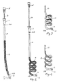
- the catheter according to the invention shown in FIGS. 1 and 2 comprises a resiliently flexible tube 10 preferably of plastic or rubber of medical quality such as polyurethane or silicone rubber, having a proximal end 10A and a distal end 10B.
- the catheter has an outside diameter of 3.6 mm and an inside diameter of 1.5 mm but it can also have other dimensions.
- the tube is provided with a guide socket 11 which communicates with the lumen of the tube, while the tube at the distal end 10B thereof is provided with a cap 12 which communicates with the lumen of the tube at one end and is closed at the other end and which has between the ends thereof radial side apertures 13.
- Socket 11 serves as a finger grip in order that the catheter can be more easily handled at the use thereof and can also be used for mounting the proximal end of the tube in a holder.
- a flexible but unelastic and relatively rigid guide 14 of steel wire rope having substantially the same length as tube 10 is displaceably received in the tube and is provided at the proximal end thereof with a finger grip 15 at which the guide can be held at displacement thereof in the tube.
- the tube Adjacent the distal end the tube has a predetermined length with inherent (programmed) tendency of coiling to substantially the shape of a screw winding (memory function) as shown in FIG. 2.
- This property can be imparted to said predetermined length of the tube by a suitable choice of the material and by heating and curing while the tube length is coiled on a core.
- the coiled portion of the tube can comprise 1 to 5 turns and can have an outside diameter of about 40 mm. When the guide is pushed into said predetermined length of the tube this length is, however, substantially straightened as shown in FIG. 1, which implies that the guide has such a stiffness that there is required in order to bend the same a force which is greater than the coiling force of the tube.
- At least the predetermined length of the tube at the distal end thereof having a tendency of coiling according to the invention is provided at the outside surface thereof with fimbriae-like short hairs as indicated at 16 in FIGS. 1 and 2 in order to stimulate the advancement of the catheter and more safely prevent dislocation thereof when it is in the predetermined position in the intestine by increased friction against the outside surface of the tube.
- this can also be achieved in another way, for example by providing on the tube a frosted, rough, or ribbed surface structure.
- Prior art electrostatic technique is well suited for providing an hairy surface on the outside of the tube.
- Said surface is made temporarily adhesive by applying some kind of glue, and short fibres of unitary length are applied on the surface in an electrostatic field, the fibres under the influence of the electrostatic field being held in a position in which they are directed radially outwards from the tube. This position will be maintained when the glue has set.
- the catheter When the catheter is being used it is inserted into the stomach through the nose or through the oral cavity via the gullet and the esophagus, or percutaneously, with the catheter straightened by the guide 14 being pushed into the predetermined length with tendency of coiling, i.e. in the condition according to FIG. 1.
- the coiled portion being dimensioned as mentioned above the tube of FIG. 1 has an effective length which is 30 mm larger than the length in the condition according to FIG. 2.
- the guide After insertion of the catheter into the stomach the guide is withdrawn a distance corresponding to said difference in effective length, i.e. about 30 mm, so that the tube will be free to coil in the stomach the tube then being advanced a corresponding distance in the stomach i.e.
- the catheter When the distal end of the catheter is located in the upper portion of jejunum the catheter will be fixed against further advancement for example by being taped against the body.
- the position of the distal end in the intestine can be controlled by X-ray, and for this purpose there can be embedded in the distal end for example in the cap a suitable contrast agent.
- the coiled length of the catheter maintains the catheter in the predetermined position in the intestine and thus functions as a dislocation lock. Due to said length being made hairy, frosted, rough or ribbed the "engagement" between the surrounding food and the catheter as well as the "engagement" between the inside surface of the intestine and the catheter will be increased without sliding of the catheter at the insertion being impeded as a consequence thereof. It is therefore expected that the catheter will be 100 % safe with regard to the self-advancement as well as the retainment in the predetermined position by arranging the catheter in the manner proposed according to the invention.
- Supply of a nutriment solution or medicaments or, alternatively, sampling takes place through the tube after the catheter being located in the predetermined position thereof.
- the tube is provided at the outside surface thereof with an axially extending radially projecting fin 17 which in the coiled length is located at the inside thereof, i.e. inside the screw shaped coil.
- a fin 18 is provided but in this case the fin is located at the outside of the coiled length.
- the fin should be thin and extendible and should be extremely soft and flexible and can consist of plastic or rubber. It may be made of the same material as the tube but this is not necessary.
- the fin may be formed at extrusion of the tube to extend not only over the predetermined length with tendency of coiling but over the total length of the tube.
- the fin can be combined with a hairy, frosted, rough or ribbed surface 16 on the tube, and on one and the same tube there may be provided two diametrically opposite fins so that the predetermined length with tendency of coiling in the coiled condition has a fin at the inside as well as the outside.
- On the inside the fin may be up to 10 mm wide while the fin at the outside should be no more than 1 á 2 mm.
- the fin extends helically around the tube.
- the fin or fins provide a further strengthened "engagement" between the catheter and the food in the stomach, and if the fin is at the outside, FIG. 4, between the catheter and the inside surface of the intestine for promoting self-advancement and strengthening of the fixation of the catheter in the predetermined position, respectively.
Abstract
Description
Claims (8)
- Catheter for providing a fluid connection with the small intestine, preferably for nutriment supply to said intestine, comprising a tube (10) to be inserted into the small intestine via the stomach having proximal and distal open ends (10A, 10B) and having inherent tendency of coiling over a predetermined length at the distal end thereof, and a guide (14) displaceable in the tube from the proximal end thereof for straightening said length in order that it will be straightened during the actual insertion in the stomach, characterized in that the tube (10) at least in said predetermined portion has a hairy, frosted, rough, ribbed or finned outside surface (16).
- Catheter as in claim 1, characterized in that an axially extending radially projecting fin (17, 18) is provided on the outside surface of the tube (10) at least along said predetermined length with tendency of coiling.
- Catheter as in claim 2, characterized in that the fin (17) in the coiled portion formed by said predetermined length is located at the inside of said portion.
- Catheter as in claim 2, characterized in that the fin (18) in the coiled portion formed by said predetermined length is located at the outside of this portion.
- Catheter as in claim 2, characterized in that the fin (17, 18) extends helically around the tube (10).
- Catheter as in any of claims 2 to 5, characterized in that the fin (17, 18) is thin and extendible as well as soft and flexible.
- Catheter as in any of claims 1 to 6, characterized in that the coiled portion formed by said predetermined length comprises 1 to 5 turns and has an outside diameter up to 40 mm.
- Probe as in any of claims 1 to 7, characterized in that a hairy surface on the tube is provided by electrostatic technique and comprises short fibres projecting radially from the surface.
Applications Claiming Priority (3)
| Application Number | Priority Date | Filing Date | Title |
|---|---|---|---|
| SE9700373A SE9700373L (en) | 1997-02-04 | 1997-02-04 | Probe for providing fluid communication with the small intestine |
| SE9700373 | 1997-02-04 | ||
| PCT/SE1998/000145 WO1998033469A1 (en) | 1997-02-04 | 1998-02-02 | Catheter for providing a fluid connection with the small intestine |
Publications (2)
| Publication Number | Publication Date |
|---|---|
| EP0963191A1 EP0963191A1 (en) | 1999-12-15 |
| EP0963191B1 true EP0963191B1 (en) | 2003-08-20 |
Family
ID=20405661
Family Applications (1)
| Application Number | Title | Priority Date | Filing Date |
|---|---|---|---|
| EP98902344A Expired - Lifetime EP0963191B1 (en) | 1997-02-04 | 1998-02-02 | Catheter for providing a fluid connection with the small intestine |
Country Status (16)
| Country | Link |
|---|---|
| US (1) | US7201738B1 (en) |
| EP (1) | EP0963191B1 (en) |
| JP (1) | JP2001509710A (en) |
| CN (1) | CN1142759C (en) |
| AT (1) | ATE247450T1 (en) |
| AU (1) | AU733326B2 (en) |
| BR (1) | BR9807552A (en) |
| CA (1) | CA2285042C (en) |
| DE (1) | DE69817330T2 (en) |
| DK (1) | DK0963191T3 (en) |
| ES (1) | ES2206884T3 (en) |
| PL (1) | PL189382B1 (en) |
| PT (1) | PT963191E (en) |
| RU (1) | RU2179461C2 (en) |
| SE (1) | SE9700373L (en) |
| WO (1) | WO1998033469A1 (en) |
Cited By (6)
| Publication number | Priority date | Publication date | Assignee | Title |
|---|---|---|---|---|
| US8834464B2 (en) | 1999-04-05 | 2014-09-16 | Mark T. Stewart | Ablation catheters and associated systems and methods |
| US8888773B2 (en) | 2012-05-11 | 2014-11-18 | Medtronic Ardian Luxembourg S.A.R.L. | Multi-electrode catheter assemblies for renal neuromodulation and associated systems and methods |
| US8934978B2 (en) | 2002-04-08 | 2015-01-13 | Medtronic Ardian Luxembourg S.A.R.L. | Methods and apparatus for renal neuromodulation |
| US8956352B2 (en) | 2010-10-25 | 2015-02-17 | Medtronic Ardian Luxembourg S.A.R.L. | Catheter apparatuses having multi-electrode arrays for renal neuromodulation and associated systems and methods |
| US9095321B2 (en) | 2012-11-21 | 2015-08-04 | Medtronic Ardian Luxembourg S.A.R.L. | Cryotherapeutic devices having integral multi-helical balloons and methods of making the same |
| US9179974B2 (en) | 2013-03-15 | 2015-11-10 | Medtronic Ardian Luxembourg S.A.R.L. | Helical push wire electrode |
Families Citing this family (34)
| Publication number | Priority date | Publication date | Assignee | Title |
|---|---|---|---|---|
| US6589213B2 (en) * | 1997-12-12 | 2003-07-08 | Wilson-Cook Medical Incorporated | Body canal intrusion instrumentation having bi-directional coefficient of surface friction with body tissue |
| US6767339B2 (en) | 1997-12-12 | 2004-07-27 | Wilson-Cook Medical, Inc. | Body canal intrusion instrumentation having bidirectional coefficient of surface friction with body tissue |
| NL1011474C2 (en) | 1999-03-05 | 2000-09-06 | Sven Ploem | Self-positioning catheter. |
| US20140018880A1 (en) | 2002-04-08 | 2014-01-16 | Medtronic Ardian Luxembourg S.A.R.L. | Methods for monopolar renal neuromodulation |
| US8774913B2 (en) | 2002-04-08 | 2014-07-08 | Medtronic Ardian Luxembourg S.A.R.L. | Methods and apparatus for intravasculary-induced neuromodulation |
| US7122048B2 (en) * | 2002-05-03 | 2006-10-17 | Scimed Life Systems, Inc. | Hypotube endoluminal device |
| US7780650B2 (en) * | 2005-05-04 | 2010-08-24 | Spirus Medical, Inc. | Rotate-to-advance catheterization system |
| US8235942B2 (en) | 2005-05-04 | 2012-08-07 | Olympus Endo Technology America Inc. | Rotate-to-advance catheterization system |
| US8343040B2 (en) * | 2005-05-04 | 2013-01-01 | Olympus Endo Technology America Inc. | Rotate-to-advance catheterization system |
| US8414477B2 (en) * | 2005-05-04 | 2013-04-09 | Olympus Endo Technology America Inc. | Rotate-to-advance catheterization system |
| DE102006008315B4 (en) * | 2006-02-18 | 2007-12-06 | Hahn-Meitner-Institut Berlin Gmbh | Miniaturized shape memory polymer transport systems and methods of manufacture |
| US8574220B2 (en) | 2006-02-28 | 2013-11-05 | Olympus Endo Technology America Inc. | Rotate-to-advance catheterization system |
| US8435229B2 (en) | 2006-02-28 | 2013-05-07 | Olympus Endo Technology America Inc. | Rotate-to-advance catheterization system |
| CA2645671A1 (en) * | 2006-03-03 | 2007-09-13 | Wilson-Cook Medical, Inc. | Endoscopic apparatus having an improved catheter |
| WO2007128064A1 (en) | 2006-05-08 | 2007-11-15 | Cathrx Ltd | Shape imparting mechanism insertion |
| WO2008121311A1 (en) * | 2007-03-29 | 2008-10-09 | Boston Scientific Scimed, Inc. | Catheter assembly including coiled internal bolster |
| US8870755B2 (en) | 2007-05-18 | 2014-10-28 | Olympus Endo Technology America Inc. | Rotate-to-advance catheterization system |
| WO2008144033A2 (en) * | 2007-05-18 | 2008-11-27 | Spirus Medical, Inc. | Rotate-to-advance catheterizaton system |
| DE202008015225U1 (en) | 2008-11-17 | 2010-04-01 | Medi-Globe Gmbh | Catheter for the treatment of obesity and obesity in a human |
| DE102009057045A1 (en) | 2009-12-04 | 2011-06-09 | Medi-Globe Gmbh | Catheter for treating overweight and obesity of patient, has hose positioned in small intestine of human being during placement of funnel-shaped inlet part at region of stomach outlet of human being |
| US8689439B2 (en) | 2010-08-06 | 2014-04-08 | Abbott Laboratories | Method for forming a tube for use with a pump delivery system |
| US9211234B2 (en) * | 2010-09-27 | 2015-12-15 | Avent, Inc. | Configurable percutaneous endoscopic gastrostomy tube |
| US8377001B2 (en) | 2010-10-01 | 2013-02-19 | Abbott Laboratories | Feeding set for a peristaltic pump system |
| US8377000B2 (en) | 2010-10-01 | 2013-02-19 | Abbott Laboratories | Enteral feeding apparatus having a feeding set |
| US10130789B2 (en) * | 2011-06-30 | 2018-11-20 | Covidien Lp | Distal access aspiration guide catheter |
| CN102614086A (en) * | 2011-08-10 | 2012-08-01 | 山东峰源医用材料有限公司 | Gastrointestinal nutrition drainage tube |
| US8574221B2 (en) | 2011-09-09 | 2013-11-05 | Cook Medical Technologies Llc | Tubular medical device |
| US20150073515A1 (en) | 2013-09-09 | 2015-03-12 | Medtronic Ardian Luxembourg S.a.r.I. | Neuromodulation Catheter Devices and Systems Having Energy Delivering Thermocouple Assemblies and Associated Methods |
| US9993250B2 (en) * | 2013-12-19 | 2018-06-12 | Kyungpook National University Industry-Academic Cooperation Foundation | Device for protecting the rectal anastomosis |
| MD795Z (en) * | 2014-01-16 | 2015-02-28 | Валерий ТИМИРГАЗ | Controlled catheter |
| JP2017513600A (en) | 2014-04-24 | 2017-06-01 | メドトロニック アーディアン ルクセンブルク ソシエテ ア レスポンサビリテ リミテ | Nerve adjustment catheter with braided shaft and related systems and methods |
| CN105126227A (en) * | 2015-09-01 | 2015-12-09 | 王兆华 | Small intestine double-contrast angiographic catheter and using method thereof |
| JP6718664B2 (en) * | 2015-09-08 | 2020-07-08 | 雄造 馬塲 | Medical tube and medical tube set |
| EP4048133A4 (en) * | 2019-10-21 | 2023-12-06 | Fractyl Health, Inc. | Systems, devices and methods for performing medical procedures in the intestine |
Family Cites Families (12)
| Publication number | Priority date | Publication date | Assignee | Title |
|---|---|---|---|---|
| US3399668A (en) * | 1966-02-28 | 1968-09-03 | Edward S. Lundgren | Disposable cholangiography catheter |
| SE459473B (en) | 1987-02-13 | 1989-07-10 | Stig Bengmark | HOSE DEVICE, SPECIFICALLY BEFORE ADMINISTRATION OF FOODS DIRECTLY IN THE GAS |
| US4834724A (en) * | 1987-04-06 | 1989-05-30 | Geiss Alan C | Device for aspirating fluids from a body cavity or hollow organ |
| US5059169A (en) * | 1989-07-07 | 1991-10-22 | C. R. Bard, Inc. | High-friction prostatic stent |
| US5256146A (en) * | 1991-10-11 | 1993-10-26 | W. D. Ensminger | Vascular catheterization system with catheter anchoring feature |
| US6743198B1 (en) * | 1995-03-20 | 2004-06-01 | Conticare Medical, Inc. | Self-cleansing bladder drainage device |
| US5601537A (en) * | 1995-06-05 | 1997-02-11 | Frassica; James J. | Catheter system |
| US5902285A (en) | 1997-01-27 | 1999-05-11 | Novartis Nutrition Ag | Jejunal feeding tube |
| JP3527378B2 (en) * | 1997-01-31 | 2004-05-17 | テルモ株式会社 | Contrast catheter |
| US5984896A (en) * | 1997-10-28 | 1999-11-16 | Ojp #73, Inc. | Fixated catheter |
| US6344038B1 (en) * | 1998-12-02 | 2002-02-05 | Paul J. Weber | Surgical anti-friction device |
| US20050245846A1 (en) * | 2004-05-03 | 2005-11-03 | Casey Don E | Vibrating, magnetically guidable catheter with magnetic powder commingled with resin, extruded as an integral part the catheter |
-
1997
- 1997-02-04 SE SE9700373A patent/SE9700373L/en not_active IP Right Cessation
-
1998
- 1998-02-02 DE DE69817330T patent/DE69817330T2/en not_active Expired - Lifetime
- 1998-02-02 AT AT98902344T patent/ATE247450T1/en not_active IP Right Cessation
- 1998-02-02 PT PT98902344T patent/PT963191E/en unknown
- 1998-02-02 PL PL98334861A patent/PL189382B1/en not_active IP Right Cessation
- 1998-02-02 JP JP53279198A patent/JP2001509710A/en not_active Ceased
- 1998-02-02 AU AU58898/98A patent/AU733326B2/en not_active Ceased
- 1998-02-02 US US09/355,665 patent/US7201738B1/en not_active Expired - Fee Related
- 1998-02-02 CA CA002285042A patent/CA2285042C/en not_active Expired - Fee Related
- 1998-02-02 BR BR9807552-7A patent/BR9807552A/en not_active Application Discontinuation
- 1998-02-02 ES ES98902344T patent/ES2206884T3/en not_active Expired - Lifetime
- 1998-02-02 CN CNB988035871A patent/CN1142759C/en not_active Expired - Fee Related
- 1998-02-02 RU RU99119231/14A patent/RU2179461C2/en not_active IP Right Cessation
- 1998-02-02 WO PCT/SE1998/000145 patent/WO1998033469A1/en active IP Right Grant
- 1998-02-02 DK DK98902344T patent/DK0963191T3/en active
- 1998-02-02 EP EP98902344A patent/EP0963191B1/en not_active Expired - Lifetime
Cited By (11)
| Publication number | Priority date | Publication date | Assignee | Title |
|---|---|---|---|---|
| US8834464B2 (en) | 1999-04-05 | 2014-09-16 | Mark T. Stewart | Ablation catheters and associated systems and methods |
| US9554848B2 (en) | 1999-04-05 | 2017-01-31 | Medtronic, Inc. | Ablation catheters and associated systems and methods |
| US8934978B2 (en) | 2002-04-08 | 2015-01-13 | Medtronic Ardian Luxembourg S.A.R.L. | Methods and apparatus for renal neuromodulation |
| US9289255B2 (en) | 2002-04-08 | 2016-03-22 | Medtronic Ardian Luxembourg S.A.R.L. | Methods and apparatus for renal neuromodulation |
| US8956352B2 (en) | 2010-10-25 | 2015-02-17 | Medtronic Ardian Luxembourg S.A.R.L. | Catheter apparatuses having multi-electrode arrays for renal neuromodulation and associated systems and methods |
| US8998894B2 (en) | 2010-10-25 | 2015-04-07 | Medtronic Ardian Luxembourg S.A.R.L. | Catheter apparatuses having multi-electrode arrays for renal neuromodulation and associated systems and methods |
| US8888773B2 (en) | 2012-05-11 | 2014-11-18 | Medtronic Ardian Luxembourg S.A.R.L. | Multi-electrode catheter assemblies for renal neuromodulation and associated systems and methods |
| US9138292B2 (en) | 2012-05-11 | 2015-09-22 | Medtronic Ardian Luxembourg S.A.R.L. | Multi-electrode catheter assemblies for renal neuromodulation and associated systems and methods |
| US9452017B2 (en) | 2012-05-11 | 2016-09-27 | Medtronic Ardian Luxembourg S.A.R.L. | Multi-electrode catheter assemblies for renal neuromodulation and associated systems and methods |
| US9095321B2 (en) | 2012-11-21 | 2015-08-04 | Medtronic Ardian Luxembourg S.A.R.L. | Cryotherapeutic devices having integral multi-helical balloons and methods of making the same |
| US9179974B2 (en) | 2013-03-15 | 2015-11-10 | Medtronic Ardian Luxembourg S.A.R.L. | Helical push wire electrode |
Also Published As
| Publication number | Publication date |
|---|---|
| CA2285042A1 (en) | 1998-08-06 |
| DE69817330T2 (en) | 2004-07-01 |
| ES2206884T3 (en) | 2004-05-16 |
| WO1998033469A1 (en) | 1998-08-06 |
| AU5889898A (en) | 1998-08-25 |
| SE507786C2 (en) | 1998-07-13 |
| DE69817330D1 (en) | 2003-09-25 |
| AU733326B2 (en) | 2001-05-10 |
| ATE247450T1 (en) | 2003-09-15 |
| SE9700373L (en) | 1998-07-13 |
| PT963191E (en) | 2003-12-31 |
| PL189382B1 (en) | 2005-07-29 |
| CN1251032A (en) | 2000-04-19 |
| US7201738B1 (en) | 2007-04-10 |
| BR9807552A (en) | 2000-02-01 |
| JP2001509710A (en) | 2001-07-24 |
| CN1142759C (en) | 2004-03-24 |
| CA2285042C (en) | 2006-10-17 |
| PL334861A1 (en) | 2000-03-27 |
| EP0963191A1 (en) | 1999-12-15 |
| SE9700373D0 (en) | 1997-02-04 |
| DK0963191T3 (en) | 2003-12-08 |
| RU2179461C2 (en) | 2002-02-20 |
Similar Documents
| Publication | Publication Date | Title |
|---|---|---|
| EP0963191B1 (en) | Catheter for providing a fluid connection with the small intestine | |
| US8192419B2 (en) | Catheter assembly including internal bolster | |
| US4755171A (en) | Tubular surgical device | |
| US3737579A (en) | Body tissue electrode and device for screwing the electrode into body tissue | |
| EP0278937B1 (en) | Method for positioning a tube in the small intestine | |
| US4435174A (en) | Catheter guide | |
| US5727555A (en) | Indwelling catheter | |
| ES2391004T3 (en) | Occlusion resistant catheters | |
| US4671795A (en) | Permanent/retrievable ureteral catheter | |
| US5358517A (en) | Electrical medical lead with textured stylet guide | |
| US6546280B2 (en) | Indwelling catheter | |
| US8016815B2 (en) | Catheter assembly including foldable internal bolster | |
| US6223070B1 (en) | Indwelling catheter | |
| CN113521503A (en) | Self-anchoring catheter and method of use | |
| US5571160A (en) | Permanently curved sleeve for shaping an electrode cable, and method for implanting the cable with the sleeve | |
| US5084024A (en) | Catheter and method for relieving catheter stress | |
| JP3549264B2 (en) | Catheter tube | |
| US5107836A (en) | Body implantable electrical signal generator with redundant lead retainer and surgical procedure | |
| US20030120216A1 (en) | Device for externally retaining a gastrostomy feeding tube against a patient and method of using said device | |
| JP2007167082A (en) | Guide instrument of in-vivo insertion tube via gastric fistula and instrument kit for changing percutaneous gastrostoma-tube to jejunum tube via gastric fistula | |
| JPH07106223B2 (en) | Medical tube | |
| AU2022320689A1 (en) | Bridle delivery system having retrieval probe with flexible distal tip | |
| AU2022318994A1 (en) | Bridle delivery system having reduced-contact bridle | |
| JPH0558153U (en) | Catheter |
Legal Events
| Date | Code | Title | Description |
|---|---|---|---|
| PUAI | Public reference made under article 153(3) epc to a published international application that has entered the european phase |
Free format text: ORIGINAL CODE: 0009012 |
|
| 17P | Request for examination filed |
Effective date: 19990816 |
|
| AK | Designated contracting states |
Kind code of ref document: A1 Designated state(s): AT BE CH DE DK ES FI FR GB GR IE IT LI LU MC NL PT SE |
|
| RAP1 | Party data changed (applicant data changed or rights of an application transferred) |
Owner name: BENGMARK, STIG |
|
| RIN1 | Information on inventor provided before grant (corrected) |
Inventor name: BENGMARK, STIG |
|
| RAP1 | Party data changed (applicant data changed or rights of an application transferred) |
Owner name: BENGMARK, STIG |
|
| RIN1 | Information on inventor provided before grant (corrected) |
Inventor name: BENGMARK, STIG |
|
| GRAH | Despatch of communication of intention to grant a patent |
Free format text: ORIGINAL CODE: EPIDOS IGRA |
|
| GRAH | Despatch of communication of intention to grant a patent |
Free format text: ORIGINAL CODE: EPIDOS IGRA |
|
| GRAA | (expected) grant |
Free format text: ORIGINAL CODE: 0009210 |
|
| AK | Designated contracting states |
Designated state(s): AT BE CH DE DK ES FI FR GB GR IE IT LI LU MC NL PT SE |
|
| REG | Reference to a national code |
Ref country code: GB Ref legal event code: FG4D |
|
| REG | Reference to a national code |
Ref country code: CH Ref legal event code: EP |
|
| REG | Reference to a national code |
Ref country code: IE Ref legal event code: FG4D |
|
| REF | Corresponds to: |
Ref document number: 69817330 Country of ref document: DE Date of ref document: 20030925 Kind code of ref document: P |
|
| REG | Reference to a national code |
Ref country code: SE Ref legal event code: TRGR |
|
| REG | Reference to a national code |
Ref country code: DK Ref legal event code: T3 |
|
| REG | Reference to a national code |
Ref country code: GR Ref legal event code: EP Ref document number: 20030404752 Country of ref document: GR |
|
| REG | Reference to a national code |
Ref country code: CH Ref legal event code: NV Representative=s name: NOVAGRAAF INTERNATIONAL SA |
|
| REG | Reference to a national code |
Ref country code: ES Ref legal event code: FG2A Ref document number: 2206884 Country of ref document: ES Kind code of ref document: T3 |
|
| ET | Fr: translation filed | ||
| PLBE | No opposition filed within time limit |
Free format text: ORIGINAL CODE: 0009261 |
|
| STAA | Information on the status of an ep patent application or granted ep patent |
Free format text: STATUS: NO OPPOSITION FILED WITHIN TIME LIMIT |
|
| 26N | No opposition filed |
Effective date: 20040524 |
|
| PGFP | Annual fee paid to national office [announced via postgrant information from national office to epo] |
Ref country code: MC Payment date: 20060203 Year of fee payment: 9 |
|
| PGFP | Annual fee paid to national office [announced via postgrant information from national office to epo] |
Ref country code: LU Payment date: 20060209 Year of fee payment: 9 |
|
| PGFP | Annual fee paid to national office [announced via postgrant information from national office to epo] |
Ref country code: GR Payment date: 20060210 Year of fee payment: 9 |
|
| REG | Reference to a national code |
Ref country code: CH Ref legal event code: PUE Owner name: N.V. NUTRICIA Free format text: BENGMARK, STIG#KUSTVAEGEN 3#263 32 HOEGANAES (SE) -TRANSFER TO- N.V. NUTRICIA#EERSTE STATIONSSTRAAT 186#2712 HM ZOETERMEER (NL) |
|
| REG | Reference to a national code |
Ref country code: GB Ref legal event code: 732E |
|
| NLS | Nl: assignments of ep-patents |
Owner name: N.V. NUTRICIA Effective date: 20060125 |
|
| REG | Reference to a national code |
Ref country code: FR Ref legal event code: TP |
|
| REG | Reference to a national code |
Ref country code: ES Ref legal event code: PC2A |
|
| PG25 | Lapsed in a contracting state [announced via postgrant information from national office to epo] |
Ref country code: MC Free format text: LAPSE BECAUSE OF NON-PAYMENT OF DUE FEES Effective date: 20070228 |
|
| PGFP | Annual fee paid to national office [announced via postgrant information from national office to epo] |
Ref country code: ES Payment date: 20080229 Year of fee payment: 11 Ref country code: DK Payment date: 20080228 Year of fee payment: 11 Ref country code: CH Payment date: 20080303 Year of fee payment: 11 |
|
| PGFP | Annual fee paid to national office [announced via postgrant information from national office to epo] |
Ref country code: SE Payment date: 20080227 Year of fee payment: 11 Ref country code: PT Payment date: 20080208 Year of fee payment: 11 Ref country code: NL Payment date: 20080228 Year of fee payment: 11 Ref country code: IT Payment date: 20080227 Year of fee payment: 11 Ref country code: IE Payment date: 20080229 Year of fee payment: 11 Ref country code: FI Payment date: 20080229 Year of fee payment: 11 |
|
| PGFP | Annual fee paid to national office [announced via postgrant information from national office to epo] |
Ref country code: AT Payment date: 20080228 Year of fee payment: 11 |
|
| PGFP | Annual fee paid to national office [announced via postgrant information from national office to epo] |
Ref country code: BE Payment date: 20080303 Year of fee payment: 11 |
|
| PG25 | Lapsed in a contracting state [announced via postgrant information from national office to epo] |
Ref country code: GR Free format text: LAPSE BECAUSE OF NON-PAYMENT OF DUE FEES Effective date: 20070904 |
|
| REG | Reference to a national code |
Ref country code: CH Ref legal event code: PCAR Free format text: NOVAGRAAF INTERNATIONAL SA;25, AVENUE DU PAILLY;1220 LES AVANCHETS (CH) |
|
| REG | Reference to a national code |
Ref country code: PT Ref legal event code: MM4A Free format text: LAPSE DUE TO NON-PAYMENT OF FEES Effective date: 20090803 |
|
| BERE | Be: lapsed |
Owner name: *NUTRICIA N.V. Effective date: 20090228 |
|
| PG25 | Lapsed in a contracting state [announced via postgrant information from national office to epo] |
Ref country code: LU Free format text: LAPSE BECAUSE OF NON-PAYMENT OF DUE FEES Effective date: 20070202 |
|
| REG | Reference to a national code |
Ref country code: CH Ref legal event code: PL |
|
| EUG | Se: european patent has lapsed | ||
| REG | Reference to a national code |
Ref country code: DK Ref legal event code: EBP |
|
| PG25 | Lapsed in a contracting state [announced via postgrant information from national office to epo] |
Ref country code: PT Free format text: LAPSE BECAUSE OF NON-PAYMENT OF DUE FEES Effective date: 20090803 Ref country code: LI Free format text: LAPSE BECAUSE OF NON-PAYMENT OF DUE FEES Effective date: 20090228 Ref country code: FI Free format text: LAPSE BECAUSE OF NON-PAYMENT OF DUE FEES Effective date: 20090202 Ref country code: CH Free format text: LAPSE BECAUSE OF NON-PAYMENT OF DUE FEES Effective date: 20090228 Ref country code: AT Free format text: LAPSE BECAUSE OF NON-PAYMENT OF DUE FEES Effective date: 20090202 |
|
| NLV4 | Nl: lapsed or anulled due to non-payment of the annual fee |
Effective date: 20090901 |
|
| REG | Reference to a national code |
Ref country code: IE Ref legal event code: MM4A |
|
| PG25 | Lapsed in a contracting state [announced via postgrant information from national office to epo] |
Ref country code: NL Free format text: LAPSE BECAUSE OF NON-PAYMENT OF DUE FEES Effective date: 20090901 |
|
| PG25 | Lapsed in a contracting state [announced via postgrant information from national office to epo] |
Ref country code: IE Free format text: LAPSE BECAUSE OF NON-PAYMENT OF DUE FEES Effective date: 20090202 |
|
| PG25 | Lapsed in a contracting state [announced via postgrant information from national office to epo] |
Ref country code: BE Free format text: LAPSE BECAUSE OF NON-PAYMENT OF DUE FEES Effective date: 20090228 |
|
| REG | Reference to a national code |
Ref country code: ES Ref legal event code: FD2A Effective date: 20090203 |
|
| PG25 | Lapsed in a contracting state [announced via postgrant information from national office to epo] |
Ref country code: ES Free format text: LAPSE BECAUSE OF NON-PAYMENT OF DUE FEES Effective date: 20090203 Ref country code: DK Free format text: LAPSE BECAUSE OF NON-PAYMENT OF DUE FEES Effective date: 20090831 |
|
| PG25 | Lapsed in a contracting state [announced via postgrant information from national office to epo] |
Ref country code: IT Free format text: LAPSE BECAUSE OF NON-PAYMENT OF DUE FEES Effective date: 20090202 |
|
| PG25 | Lapsed in a contracting state [announced via postgrant information from national office to epo] |
Ref country code: SE Free format text: LAPSE BECAUSE OF NON-PAYMENT OF DUE FEES Effective date: 20090203 |
|
| REG | Reference to a national code |
Ref country code: FR Ref legal event code: PLFP Year of fee payment: 19 |
|
| PGFP | Annual fee paid to national office [announced via postgrant information from national office to epo] |
Ref country code: DE Payment date: 20160216 Year of fee payment: 19 |
|
| PGFP | Annual fee paid to national office [announced via postgrant information from national office to epo] |
Ref country code: FR Payment date: 20160218 Year of fee payment: 19 Ref country code: GB Payment date: 20160217 Year of fee payment: 19 |
|
| REG | Reference to a national code |
Ref country code: DE Ref legal event code: R119 Ref document number: 69817330 Country of ref document: DE |
|
| GBPC | Gb: european patent ceased through non-payment of renewal fee |
Effective date: 20170202 |
|
| REG | Reference to a national code |
Ref country code: FR Ref legal event code: ST Effective date: 20171031 |
|
| PG25 | Lapsed in a contracting state [announced via postgrant information from national office to epo] |
Ref country code: FR Free format text: LAPSE BECAUSE OF NON-PAYMENT OF DUE FEES Effective date: 20170228 Ref country code: DE Free format text: LAPSE BECAUSE OF NON-PAYMENT OF DUE FEES Effective date: 20170901 |
|
| PG25 | Lapsed in a contracting state [announced via postgrant information from national office to epo] |
Ref country code: GB Free format text: LAPSE BECAUSE OF NON-PAYMENT OF DUE FEES Effective date: 20170202 |