EP0963790A2 - Microtitration plate - Google Patents
Microtitration plate Download PDFInfo
- Publication number
- EP0963790A2 EP0963790A2 EP99111216A EP99111216A EP0963790A2 EP 0963790 A2 EP0963790 A2 EP 0963790A2 EP 99111216 A EP99111216 A EP 99111216A EP 99111216 A EP99111216 A EP 99111216A EP 0963790 A2 EP0963790 A2 EP 0963790A2
- Authority
- EP
- European Patent Office
- Prior art keywords
- chambers
- chamber
- light
- lens
- optical lens
- Prior art date
- Legal status (The legal status is an assumption and is not a legal conclusion. Google has not performed a legal analysis and makes no representation as to the accuracy of the status listed.)
- Withdrawn
Links
Images
Classifications
-
- B—PERFORMING OPERATIONS; TRANSPORTING
- B01—PHYSICAL OR CHEMICAL PROCESSES OR APPARATUS IN GENERAL
- B01L—CHEMICAL OR PHYSICAL LABORATORY APPARATUS FOR GENERAL USE
- B01L3/00—Containers or dishes for laboratory use, e.g. laboratory glassware; Droppers
- B01L3/50—Containers for the purpose of retaining a material to be analysed, e.g. test tubes
- B01L3/508—Containers for the purpose of retaining a material to be analysed, e.g. test tubes rigid containers not provided for above
- B01L3/5085—Containers for the purpose of retaining a material to be analysed, e.g. test tubes rigid containers not provided for above for multiple samples, e.g. microtitration plates
-
- G—PHYSICS
- G01—MEASURING; TESTING
- G01N—INVESTIGATING OR ANALYSING MATERIALS BY DETERMINING THEIR CHEMICAL OR PHYSICAL PROPERTIES
- G01N21/00—Investigating or analysing materials by the use of optical means, i.e. using sub-millimetre waves, infrared, visible or ultraviolet light
- G01N21/62—Systems in which the material investigated is excited whereby it emits light or causes a change in wavelength of the incident light
- G01N21/63—Systems in which the material investigated is excited whereby it emits light or causes a change in wavelength of the incident light optically excited
- G01N21/64—Fluorescence; Phosphorescence
- G01N21/645—Specially adapted constructive features of fluorimeters
- G01N21/6452—Individual samples arranged in a regular 2D-array, e.g. multiwell plates
Definitions
- the invention relates to a plate with a plurality of chambers for use especially in microbiology, where at least the bottom of the chambers is translucent is.
- Such plates are called microtiter plates or Micro Well® plates. She are used in numerous areas (biochemistry, molecular biology, clinical chemistry, analytics), i.a. in antibody screening, serological testing, storage and screening of Components and DNA libraries used.
- the plates are usually made transparent material, e.g. Polystyrene, manufactured and thus enable optical measurements, e.g. Luminance measurements, with diodes arranged under the chambers.
- the object of the invention is therefore to provide a plate according to the preamble, in which the Light scatter is significantly reduced and a more precise measurement is possible.
- This object is achieved in that one in the area of the bottom Chamber an optical lens or light reflecting means are provided.
- the light scattering can be effective through this lens or the light-reflecting means can be reduced so that a more precise optical measurement is possible.
- optical lens is a convex lens.
- the convex lens bundles the light onto one under the Chamber arranged measuring diode passed.
- optical lens is a concave lens is.
- a concave lens can also be advantageous.
- the bottom of the chamber is designed as an optical lens is.
- the light-reflecting means in the bottom of the chamber are arranged.
- optical lens encompasses the wall of the chamber.
- the light reflecting means comprise the wall of the chamber.
- Another embodiment of the invention is that below the bottom of the chamber an optical lens or light reflecting means is arranged.
- the light scatter is reduced to a lesser extent than during training the bottom of the chamber as an optical lens or as a light reflecting means, nevertheless results a reduction in the scatter compared to the prior art.
- This training the Invention can be implemented relatively easily by placing on the underside of the base plate an optical lens or light-reflecting means is arranged below each chamber become.
- the light-reflecting means as Prism are formed.
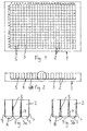
- a (microtiter) plate 1 As shown in FIG. 1, a (microtiter) plate 1 according to the invention consists of an approx. 1 cm high polystyrene rectangle, in which in rows (here 16 rows) chambers 2 (here 24 Chambers per row) are arranged.
- the chambers 2 have one in the example shown square cross-section, but also plates 1 with other, e.g. round, Chamber cross section are possible.
- the bottom 3 of the chambers 2 is covered by a bottom plate 4 formed, which extends over the entire area of the plate 1 provided with chambers 2.
- the chambers 2 in the example shown also have common, continuous walls 5, results from optical measuring methods, e.g. luminometric method, due to the Light conduction in the floor 3 and the walls 5, a strong scattering of the measuring light over the Chambers 2 away. This leads to a falsification of the measurement results.
- the bottom 3 of the chambers 2 as optical Lens 6 is formed, preferably as a convex lens.
- the bottom 3 of the chambers 2 can also be used as a light-reflecting means 8, e.g. as a prism, so that the light reflects towards the opening of the chambers 3 becomes. This is advantageous if the measurement is made from above.
- the shape of the bottom 3 (e.g. flat, sloping towards the center) of the chambers 2 is determined by the in or optical lens 6 arranged under the floor or the light-reflecting means 8 unaffected.
Abstract
Description
Die Erfindung betrifft eine Platte mit einer Vielzahl von Kammern zur Verwendung insbesondere in der Mikrobiologie, wobei zumindest der Boden der Kammern lichtdurchlässig ist.The invention relates to a plate with a plurality of chambers for use especially in microbiology, where at least the bottom of the chambers is translucent is.
Derartige Platten werden als Mikrotiterplatten oder als Micro Well®-Platten bezeichnet. Sie werden in zahlreichen Bereichen (Biochemie, Molekularbiologie, Klinische Chemie, Analytik), u.a. bei Antikörper-Screenings, serologischen Tests, Lagerung und Screening von Komponenten und DNA-Bibliotheken verwendet. Die Platten sind in der Regel aus transparentem Material, z.B. Polystyrol, gefertigt und ermöglichen so optische Messungen, z.B. Luminiszenzmessungen, mit unter den Kammern angeordneten Dioden. Typischerweise sind auf einer Platte derzeit 6 Kammern, 96 Kammern (8 Reihen à 12 Kammern) oder auch 384 Kammern (16 Reihen à 24 Kammern) in parallelen Reihen angeordnet, die je nach Anwendungsgebiet einen runden, flachen, konischen oder C-förmigen Boden aufweisen.Such plates are called microtiter plates or Micro Well® plates. she are used in numerous areas (biochemistry, molecular biology, clinical chemistry, analytics), i.a. in antibody screening, serological testing, storage and screening of Components and DNA libraries used. The plates are usually made transparent material, e.g. Polystyrene, manufactured and thus enable optical measurements, e.g. Luminance measurements, with diodes arranged under the chambers. Typically are currently 6 compartments, 96 compartments (8 rows of 12 compartments) or also on one plate 384 chambers (16 rows of 24 chambers each) arranged in parallel rows depending on the Application area have a round, flat, conical or C-shaped bottom.
Da die Böden der Kammern in der Regel in einer durchgehenden Platte angeordnet sind, ergibt sich bei den optischen Messungen eine Streuung des Lichtes, die sowohl bei Messungen von der Öffnungsseite der Kammer als auch bei Messungen von der Kammerunterseite zu einer Beeinträchtigung der Meßergebnisse führen kann. Des weiteren kann sich eine Streuung des Lichtes über die Wände der Kammern ergeben.Since the floors of the chambers are usually arranged in a continuous plate, results there is a scattering of the light in the optical measurements, which occurs both in measurements of the opening side of the chamber as well as for measurements from the underside of the chamber to one Can impair the measurement results. Furthermore, a spread of the Illuminate the walls of the chambers.
Aufgabe der Erfindung ist es somit, eine Platte gemäß dem Oberbegriff zu schaffen, bei der die Lichtstreuung deutlich reduziert und somit eine genauere Messung möglich ist.The object of the invention is therefore to provide a plate according to the preamble, in which the Light scatter is significantly reduced and a more precise measurement is possible.
Diese Aufgabe wird erfindungsgemäß dadurch gelöst, daß im Bereich des Bodens einer Kammer eine optische Linse oder lichtreflektierende Mittel vorgesehen sind.This object is achieved in that one in the area of the bottom Chamber an optical lens or light reflecting means are provided.
Durch diese Linse bzw. die lichtreflektierenden Mittel kann die Lichtstreuung wirksam vermindert werden, so daß eine präzisere optische Messung möglich ist.The light scattering can be effective through this lens or the light-reflecting means can be reduced so that a more precise optical measurement is possible.
Eine Weiterbildung der Erfindung besteht darin, daß die optische Linse eine Konvexlinse ist.A further development of the invention is that the optical lens is a convex lens.
In vorteilhafter Weise wird durch die Konvexlinse das Licht gebündelt auf eine unter der Kammer angeordnete Meßdiode geleitet. Advantageously, the convex lens bundles the light onto one under the Chamber arranged measuring diode passed.
Eine andere Ausbildung der Erfindung besteht darin, daß die optische Linse eine Konkavlinse ist.Another embodiment of the invention is that the optical lens is a concave lens is.
Je nach Anwendungsgebiet kann auch eine Konkavlinse von Vorteil sein.Depending on the area of application, a concave lens can also be advantageous.
Es liegt im Rahmen der Erfindung, daß der Boden der Kammer als optische Linse ausgebildet ist.It is within the scope of the invention that the bottom of the chamber is designed as an optical lens is.
Hierdurch wird die Streuung des Lichtes am wirksamsten vermindert, da im Bereich des Bodens der Kammer die Streuung hervorgerufen wird.As a result, the scattering of the light is most effectively reduced, since in the range of Bottom of the chamber the scattering is caused.
Ebenso ist es vorteilhaft, daß in dem Boden der Kammer die lichtreflektierenden Mittel angeordnet sind.It is also advantageous that the light-reflecting means in the bottom of the chamber are arranged.
Es ist vorteilhaft, daß die optische Linse die Wand der Kammer umfaßt.It is advantageous that the optical lens encompasses the wall of the chamber.
Ebenso ist es zweckmäßig, daß die lichtreflektierenden Mittel die Wand der Kammer umfassen.It is also appropriate that the light reflecting means comprise the wall of the chamber.
Eine andere Ausbildung der Erfindung besteht darin, daß unterhalb des Bodens der Kammer eine optische Linse oder lichtreflektierende Mittel angeordnet ist.Another embodiment of the invention is that below the bottom of the chamber an optical lens or light reflecting means is arranged.
Hierdurch wird zwar die Lichtstreuung in geringerem Maße reduziert als bei der Ausbildung des Bodens der Kammer als optische Linse bzw. als lichtreflektierende Mittel, dennoch ergibt sich gegenüber dem Stand der Technik eine Verminderung der Streuung. Diese Ausbildung der Erfindung kann relativ leicht realisiert werden, indem auf der Unterseite der Bodenplatte unterhalb einer jeden Kammer eine optische Linse bzw. lichreflektierende Mittel angeordnet werden.As a result, the light scatter is reduced to a lesser extent than during training the bottom of the chamber as an optical lens or as a light reflecting means, nevertheless results a reduction in the scatter compared to the prior art. This training the Invention can be implemented relatively easily by placing on the underside of the base plate an optical lens or light-reflecting means is arranged below each chamber become.
Es kann zweckmäßig sein, daß in der Mitte einer zwischen zwei Kammern angeordneten gemeinsamen Wand ein optisch reflektierende Fläche oder eine lichtundurchlässige Fläche vorgesehen ist.It may be appropriate that one arranged in the middle between two chambers common wall an optically reflective surface or an opaque surface is provided.
Dies führt zu einer weiteren Verminderung der Lichtstreuung, da die Wand der Kammer in ihrem unteren Bereich mit der die Streuung des Lichtes verursachenden Bodenplatte verbunden ist.This leads to a further reduction in light scattering, since the wall of the chamber is in its lower area with the base plate causing the scattering of the light connected is.
Schließlich ist im Rahmen der Erfindung vorgesehen, daß die lichtreflektierenden Mittel als Prisma ausgebildet sind. Finally, it is provided in the context of the invention that the light-reflecting means as Prism are formed.
Die Vorteile der Erfindung bestehen somit darin, daß die Lichtstreuung wirksam vermindert werden kann und somit eine höhere Meßgenauigkeit erzielbar ist.The advantages of the invention are thus that light scattering is effectively reduced can be and thus a higher measurement accuracy can be achieved.
Im folgenden wird ein Ausführungsbeispiel der Erfindung anhand von Zeichnungen dargestellt.An exemplary embodiment of the invention is illustrated below with the aid of drawings.
Es zeigen
- Fig. 1
- eine Draufsicht auf eine erfindungsgemäße Platte,
- Fig. 2
- eine Seitenansicht einer erfindungsgemäßen Platte,
- Fig. 3a und Fig 3b
- Detailansichten des Kreisinhaltes zu Fig. 2.
- Fig. 1
- a plan view of a plate according to the invention,
- Fig. 2
- a side view of a plate according to the invention,
- 3a and 3b
- Detailed views of the contents of the circle in FIG. 2.
Wie in Fig. 1 dargestellt, besteht eine erfindungsgemäße (Mikrotiter-)Platte 1 aus einem ca. 1
cm hohen Polystyrol-Rechteck, in dem in Reihen (hier 16 Reihen) Kammern 2 (hier 24
Kammern pro Reihe) angeordnet sind. Die Kammern 2 weisen im dargestellten Beispiel einen
quadratischen Querschnitt auf, wobei allerdings auch Platten 1 mit anderem, z.B. rundem,
Kammerquerschnitt möglich sind.As shown in FIG. 1, a (microtiter)
Wie aus Fig. 2 ersichtlich ist, wird der Boden 3 der Kammern 2 durch eine Bodenplatte 4
gebildet, die sich über die gesamte mit Kammern 2 versehene Fläche der Platte 1 erstreckt. Da
die Kammern 2 im gezeigten Beispiel zudem gemeinsame, durchgehende Wände 5 aufweisen,
ergibt sich bei optischen Meßverfahren, z.B. luminometrischen Verfahren, aufgrund der
Lichtleitung in dem Boden 3 und den Wänden 5, eine starke Streuung des Meßlichtes über die
Kammern 2 hinweg. Dies führt zu einer Verfälschung der Meßergebnisse.As can be seen from FIG. 2, the
Erfindungsgemäß ist daher vorgesehen (Fig. 3a), daß der Boden 3 der Kammern 2 als optische
Linse 6 ausgebildet ist, und zwar vorzugsweise als Konvexlinse. Besonders vorteilhaft ist die
Einbeziehung der Wände 5 der Kammer 2 in die optische Linse, was insbesondere bei
Kammern 2 mit rundem Querschnitt leicht zu realisieren ist, da dort die Wände 5 zweier
benachbarter Kammern 2 nur in einem kleinen Bereich zusammenstoßen.According to the invention it is therefore provided (Fig. 3a) that the
Alternativ (Fig. 3b) kann der Boden 3 der Kammern 2 auch als lichtreflektierendes Mittel 8,
z.B. als Prisma, ausgebildet sein, so daß das Licht zur Öffhung der Kammern 3 hin reflektiert
wird. Dies ist dann vorteilhaft, wenn die Messung von oben erfolgt. Alternatively (FIG. 3b), the
Die Form des Bodens 3 (z.B. flach, zur Mitte hin abfallend) der Kammern 2 wird durch die in
bzw. unter dem Boden angeordnete optische Linse 6 oder die lichtreflektierenden Mittel 8
nicht beeinflußt.The shape of the bottom 3 (e.g. flat, sloping towards the center) of the
In dem Bereich, in dem zwei Kammern 2 eine gemeinsame Wand 5 aufweisen, ist es
vorteilhaft, eine optisch reflektierende Fläche 7 oder eine lichtundurchlässige Fläche (z.B. eine
schwarze Fläche) vorzusehen, wodurch erreicht wird, daß die Kammern 2 jeweils getrennte
optische Systeme mit minimaler Lichtstreuung sind.It is in the area in which two
Claims (10)
Applications Claiming Priority (4)
| Application Number | Priority Date | Filing Date | Title |
|---|---|---|---|
| DE29810241U | 1998-06-09 | ||
| DE29810241 | 1998-06-09 | ||
| DE29810554U | 1998-06-16 | ||
| DE29810554U DE29810554U1 (en) | 1998-06-09 | 1998-06-16 | plate |
Publications (2)
| Publication Number | Publication Date |
|---|---|
| EP0963790A2 true EP0963790A2 (en) | 1999-12-15 |
| EP0963790A3 EP0963790A3 (en) | 2000-08-16 |
Family
ID=26061572
Family Applications (1)
| Application Number | Title | Priority Date | Filing Date |
|---|---|---|---|
| EP99111216A Withdrawn EP0963790A3 (en) | 1998-06-09 | 1999-06-09 | Microtitration plate |
Country Status (1)
| Country | Link |
|---|---|
| EP (1) | EP0963790A3 (en) |
Cited By (2)
| Publication number | Priority date | Publication date | Assignee | Title |
|---|---|---|---|---|
| WO2002073172A2 (en) * | 2001-03-09 | 2002-09-19 | Gnothis Holding Sa | Determination of analytes by means of fluorescence correlation spectroscopy |
| WO2014140181A1 (en) * | 2013-03-15 | 2014-09-18 | Unisense Fertilitech A/S | A tray, a system and a method for monitoring and culturing of a cell culture |
Citations (4)
| Publication number | Priority date | Publication date | Assignee | Title |
|---|---|---|---|---|
| US4956150A (en) * | 1985-11-27 | 1990-09-11 | Alerchek | Disposable microtiter stick |
| US5171995A (en) * | 1990-09-28 | 1992-12-15 | Bruker Analytische Mebtechnik Gmbh | Sample holder for optical spectrometer and method for taking a spectrum |
| EP0589691A2 (en) * | 1992-09-23 | 1994-03-30 | Wallac Oy | Preventing optical crosstalk between liquid scintillation samples in translucent sample plates |
| EP0816828A2 (en) * | 1996-06-27 | 1998-01-07 | Perkin-Elmer Limited | Reflectance sampler |
-
1999
- 1999-06-09 EP EP99111216A patent/EP0963790A3/en not_active Withdrawn
Patent Citations (4)
| Publication number | Priority date | Publication date | Assignee | Title |
|---|---|---|---|---|
| US4956150A (en) * | 1985-11-27 | 1990-09-11 | Alerchek | Disposable microtiter stick |
| US5171995A (en) * | 1990-09-28 | 1992-12-15 | Bruker Analytische Mebtechnik Gmbh | Sample holder for optical spectrometer and method for taking a spectrum |
| EP0589691A2 (en) * | 1992-09-23 | 1994-03-30 | Wallac Oy | Preventing optical crosstalk between liquid scintillation samples in translucent sample plates |
| EP0816828A2 (en) * | 1996-06-27 | 1998-01-07 | Perkin-Elmer Limited | Reflectance sampler |
Cited By (6)
| Publication number | Priority date | Publication date | Assignee | Title |
|---|---|---|---|---|
| WO2002073172A2 (en) * | 2001-03-09 | 2002-09-19 | Gnothis Holding Sa | Determination of analytes by means of fluorescence correlation spectroscopy |
| WO2002073172A3 (en) * | 2001-03-09 | 2003-10-30 | Gnothis Holding Sa | Determination of analytes by means of fluorescence correlation spectroscopy |
| JP2004527742A (en) * | 2001-03-09 | 2004-09-09 | グノーティス ホールディング ソシエテ アノニム | Analyte determination by fluorescence-correlation spectroscopy |
| WO2014140181A1 (en) * | 2013-03-15 | 2014-09-18 | Unisense Fertilitech A/S | A tray, a system and a method for monitoring and culturing of a cell culture |
| US10047331B2 (en) | 2013-03-15 | 2018-08-14 | Unisense Fertilitech A/S | Tray, a system and a method for monitoring and culturing of a cell culture |
| EP2781591A1 (en) * | 2013-03-19 | 2014-09-24 | Unisense Fertilitech A/S | A tray, a system and a method for monitoring and culturing of a cell culture |
Also Published As
| Publication number | Publication date |
|---|---|
| EP0963790A3 (en) | 2000-08-16 |
Similar Documents
| Publication | Publication Date | Title |
|---|---|---|
| DE3005508C2 (en) | ||
| DE3118349C2 (en) | ||
| DE19507234B4 (en) | Vehicle signal light with several LEDs | |
| DE19914279C1 (en) | Sensor for optical examination of stimulated sample pixels on e.g. nano-titration screening plates or bio-chips for gene analysis, employs e.g. a liquid crystal matrix shutter and fiber optics with photomultiplier detection | |
| DE4013588C2 (en) | Device for the detection of immunological agglutination | |
| DE19711564C2 (en) | Optical switching element and switching arrangement | |
| EP0019871B1 (en) | Cuvette for the optical examination of fluids | |
| DE19830120B4 (en) | Optoelectronic sensor device | |
| DE19844316A1 (en) | Illuminated display scale device | |
| EP2962088A1 (en) | Inspection device with optical channel made of channel elements | |
| EP2386357A1 (en) | Micro-cuvette assembly and its application | |
| DE19644918C2 (en) | Micromechanical optical switching unit | |
| EP0113118A2 (en) | Cuvette for carrying out a photometric measurement | |
| EP3655289A1 (en) | Component for a vehicle | |
| DE2548728A1 (en) | DEVICE AND METHOD FOR THE ANALYTICAL DETERMINATION OF SUBSTANCES IN SOLUTION | |
| EP0963790A2 (en) | Microtitration plate | |
| DE60125844T2 (en) | Fluidically improved in vitro diagnostic test chamber | |
| EP1397201B2 (en) | Reaction vessel for producing samples | |
| DE60221979T2 (en) | ENERGY RADIATION FOR AN ELECTROPHORES SYSTEM | |
| DE19500214A1 (en) | Switching between optical signal lines | |
| AT510898B1 (en) | MENISKUS EQUILIBRATION SYSTEM FOR A MICROTITER PLATE | |
| DE10042999A1 (en) | Positioning device, used for glass microtiter plates for analyzing chemical and biological samples, comprises a holding frame, a support surface partially surrounded by lateral protrusions | |
| EP3184989B1 (en) | Cuvette | |
| AT400638B (en) | Cuvette (cell) | |
| DE102010001714A1 (en) | Apparatus and method for the optical parallel analysis of a sample arrangement and corresponding production method |
Legal Events
| Date | Code | Title | Description |
|---|---|---|---|
| PUAI | Public reference made under article 153(3) epc to a published international application that has entered the european phase |
Free format text: ORIGINAL CODE: 0009012 |
|
| AK | Designated contracting states |
Kind code of ref document: A2 Designated state(s): AT BE CH CY DE DK ES FI FR GB GR IE IT LI LU MC NL PT SE |
|
| AX | Request for extension of the european patent |
Free format text: AL;LT;LV;MK;RO;SI |
|
| PUAL | Search report despatched |
Free format text: ORIGINAL CODE: 0009013 |
|
| AK | Designated contracting states |
Kind code of ref document: A3 Designated state(s): AT BE CH CY DE DK ES FI FR GB GR IE IT LI LU MC NL PT SE |
|
| AX | Request for extension of the european patent |
Free format text: AL;LT;LV;MK;RO;SI |
|
| AKX | Designation fees paid | ||
| STAA | Information on the status of an ep patent application or granted ep patent |
Free format text: STATUS: THE APPLICATION IS DEEMED TO BE WITHDRAWN |
|
| 18D | Application deemed to be withdrawn |
Effective date: 20010217 |
|
| REG | Reference to a national code |
Ref country code: DE Ref legal event code: 8566 |