BACKGROUND OF THE INVENTION
This invention relates to resource management in a computing environment
where a resource manager is required to control allocation of a resource to competing
computing processes.
The invention finds particular, but not exclusive application, to
telecommunications apparatus where a plurality of competing processes require access
to a telephony resource, such as a modem device.
Classical solutions to resource management in such an environment involve a
resource manager model where a single entity provides an "acquire resource" and
"release resource" primitives, whereby would-be users of this resource ask the entity for
access to the resource. Access may be granted or refused as appropriate.
If access to the resource is granted, the requesting process becomes the owner of
the resource until such time as it chooses to relinquish it by performing a "release
resource" operation. During its period of ownership, the owner of the resource has
exclusive use of it, whereby the aim of the resource management scheme is achieved.
Many specific examples of this type of arrangement are known.
However, this type of arrangement, although widely used, has a major weakness.
If the current resource owner (frequently a separate unit of execution such as a thread)
falls, and exits, due to software or another error, then the resource may end up in a
permanently unavailable state because the current owner has failed to perform a "release
resource" operation before terminating.
Conventional software design either ignores this problem or tries to avoid it by
having the resource requester attempt to clean up (release the resource) before exiting.
This, however, cannot always be achieved in a reliable manner. Indeed, with such an
arrangement, the resource manager must rely on all of the resource requesters behaving
in a reliable and deterministic manner in order to provide overall reliable system
operation.
This reliance on the individual requesting processes is a significant weakness in
many systems, particularly where those processes may be provided by third party
vendors, and the quality of the processes may not always be guaranteed.
Accordingly, an aim of the present invention is to provide more reliable resource
management.
SUMMARY OF THE INVENTION
Particular and preferred aspects of the invention are set out in the accompanying
independent and dependent claims. Combinations of features from the dependent
claims may be combined with features of the independent claims as appropriate and not
merely as explicitly set out in the claims.
In accordance with one aspect of the invention, there is provided a resource
manager operable to control allocation of a resource to competing computing processes,
the resource manager being responsive to identification of a thread for a first process
requesting allocation of the resource, when the resource is already allocated to a thread
for a second process, to establish a joining function to the thread for the second process.
The joining function is operable to notify the resource manager on termination of the
thread for the second process. The resource manager can thereby be operable in
response to termination of the thread for the second process to allocate the resource to
the first process.
An embodiment of the invention is able to provide reliable resource
management through the use of a joining function which enables the resource manager
simply to join to the thread which is the current resource owner. Such a joining function
is a standard language component of, for example, the Java™ language. Accordingly, a
resource manager in accordance with an embodiment of the invention, can be provided
with a single method "acquireDevice()" which may be called by any process, or
application, wishing to use a resource (e.g., a telephony device such as a modem).
Standard language primitives ensure that only one application may execute this method
at one time, thereby guaranteeing exclusive access. The would-be owning application
can identify its operating thread to the resource manager. By effecting the join on the
thread which is the current resource owner, the resource manager is able simply to wait
until the owning application thread terminates, at which time the join language function
notifies the resource manager that the previously owning application has terminated.
This notification is provided by the language constructs irrespective of the manner in
which the previous owning application terminated. The resource manager is then able
to allocate the resource to the requesting application.
Accordingly, an embodiment of the invention avoids the problem associated
with a "release resource" primitive. An embodiment of the present invention provides
the advantages of being simple to implement, and more robust than a conventional
"release resource" approach. It also removes the reliance upon the applications
replicitly releasing the resource, whereby extremely reliable operation can be achieved
without making high demands on the competing processes.
In one embodiment of the invention, resource manager comprises object-oriented
computer software operable in an object oriented environment and the
processes are software applications operable in the object oriented environment.
In one embodiment, the software applications comprise one or more bean
objects registrable with the resource manager and the resource manager comprises one
or more objects of the Java language. The resource manager provides an
acquire Device() method which can be called by an application requesting control of the
resource. Through the use of the join function of the Java language, a language event
passively releases a resource on termination of a thread identified by the join function.
In an embodiment the resource manager controls access by a plurality of
telecommunications applications to a telephony device in a telecommunications
apparatus. The resource manager can also provide a dispatch mechanism for controlling
dispatching of a call received by the telephony device to the telecommunications
applications.
The resource manager can be provided as a computer software product on a
carrier medium, such as a data storage or a data transmission medium. Alternatively, or
in addition, at least part of the management mechanism may be embedded, or
hardwired, in a device such as an ASIC.
In accordance with another aspect of the invention, there is provided a
telecommunications apparatus including at least one telephony resource for connection
to a telecommunications network and a resource manager as defined above. The
telephony resource can be an interface to the telecommunications network, such as a
modem, whereby the resource manager controls access via the telephony resource to an
external telecommunications network by, for example, call processing applications.
The call processing applications, may, for example, be selected from a call
answering application, a voicemail application, a facsimile application and a data
application.
In accordance with a further aspect of the invention, there is provided a
computer-implemented method of managing allocation of a resource to competing
processes, the method including:
BRIEF DESCRIPTION OF THE DRAWINGS
Exemplary embodiments of the present invention will be described hereinafter,
by way of example only, with reference to the accompanying drawings in which like
reference signs relate to like elements and in which:
DESCRIPTION OF THE PREFERRED EMBODIMENTS
Figure 1 is a schematic overview of telecommunications apparatus for
implementing an embodiment consistent with the present invention.
As shown in Figure 1, a telecommunications device 10 comprises a
microprocessor 12 with associated read only memory 14, (which may be implemented
as electrically erasable programmable read only memory (EEPROM)), and random
access memory (RAM) 16. The microprocessor is connected to a communications
controller 18 (in the present example implemented as an ASIC) via a PCI bus 13. In
other embodiments other bus protocols could be used. A clock generator 20 provides
clock signals for controlling the operation of the device 10. RJ11 ports 22 and 24 are
provided for connection to telephone lines 23 and 25 at a user's premises. It will be
appreciated that RJ11 connectors may be replaced by alternative connectors as used by a
local telecommunications system.
Modems 30 and 32 are connected to the RJ11 connectors 22 and 24 for
connecting the communications controller 18 to the telephone lines 23 and 25 at the
user's premises. Although modem devices 30 and 32 are provided and the example of
the device shown in Figure 1 is intended for use with analogue telephone lines, it will be
appreciated that alternative interfaces can be provided for direct connection to digital
telephone lines (for example ISDN). Similarly, suitable connections for cable, wireless,
satellite and other telecommunication services can be provided.
Also connected to the communications controller 18 is a hub controller 34 which
itself is connected to RJ45 connectors 36, 38, 40 and 42 for the connection of personal
computers, or workstations or other computing devices to the telecommunications
device 10. In the present instance four RJ45 connectors are provided, although other
numbers of RJ45 connectors could be provided in other examples of the device 10 as
shown in Figure 1. As well as parallel RJ45 type connectors for connections to
computer equipment, other digital interfaces (not shown) could be provided in the form
of, by way of examples, a serial port, a USB port, a firewire connector, etc. Persistent
storage in the form of a disc drive 50 is connected to the communications controller
which, in the present instance, also provides the functions of a disc controller.
Alternatively, a separate disc controller could be provided externally to the
communications controller 18. Other forms of persistent storage, for example solid state
storage, could be provided in addition to or instead of the disc drive 50. A key
button/LED interface 52 allows the connection of LED indicators 56 and key buttons
54 for the display of information and for the input of information. Other forms of input
and/or output devices, such as a keyboard, a display, a pointing device, etc., could be
provided in addition to or instead of the LED indicators and key buttons.
A coder-decoder (CODEC 58) is provided for the connection of loudspeakers 60
and a microphone 62 for the output and input of audio information. An infra-red unit 64
can be provided to enable infra-red control of the device 10 and/or for infra-red porting
of information between the device 10 and another device, such as for example a
computer.
Figure 2 is a schematic overview of the software/hardware interface in the
device 10. As shown in Figure 2, an operating system 72 resides on the hardware 70 of
the telecommunications device 10. All services and applications in the particular
embodiment of the device are based on the Java™ Development Kit 74. A web server
78 provides complete internet web and proxy server functions with support for
pluggable servlets. The web server 78 and the servlets may be compatible with the Java
programming environment. It includes a built-in configurable cache and enables web
page updates to be batch loaded and preloaded. An object-oriented database 76 is
provided for persistent data storage, the database 76 being held on the disc drive 50 in
the present example of the device 10.
A text to speech system (TTS) 82 converts text into audible speech, which can
be played back on the speakers 60 or on a telephone connected to the
telecommunications device 10. A telephony platform 80 completes the main software
platform on which applications reside.
A post office and address pool service 86 provides unified messaging through
the integration of voicemail, e-mail, facsimile and paging services. Messages can be
accessed by phone and personal computer locally, or remotely. Users can also access
messages via any Point of Presence (POP) e-mail client or HyperText Markup Language
(HTML) web browser.
A voicemail application 88 provides voicemail and answering machine services.
It functions as an answering machine configurable for voicemail. The buttons 54 can
be used to provide play and delete functions, and the answering machine functions are
also accessible through the telephone and voicemail. Various telephony functions such
as smart ring detection, caller identity (ID) and automatic announcements based on
preselected parameters, such as caller ID, ring type, time of day, date and so on, can be
provided.
An e-mail application 90 provides e-mail functionality which is accessible
locally and remotely. A fax application 92 provides fax services, and a paging
application 94 provides paging services. Other services 96 may be provided by other
applications such as, for example, an address book function.
Accordingly, the telecommunications device 10 provides a unified interface for
incoming and outgoing communication. It allows users to compose e-mail messages, as
well as to forward and receive faxes and voicemails as e-mails. Access to all of the
functionality of the device can be achieved by means of a web browser via, for example,
a HTML, or Java front end.
Figure 3 is a schematic overview representing the use of the telecommunications
device 10 at a subscriber location with, connected thereto, a personal computer or
workstation 100. First and second telephone lines 106 and 108 connect the
telecommunications device to a public switched telephone network (PSTN) 110. The
connection to the PSTN can be by analogue or digital connection, either directly or
indirectly, via a cable, wireless, satellite or any other manner. Optionally, a telephone
102 and a facsimile (fax) machine 104 may also be connected to the lines 106 and 108.
Through the telecommunications device, communications may be made to another such
telecommunications device 101, a remote pager 112, a remote personal computer or
workstation 114, a remote telephone 116, a remote server station 118, and so on.
Figure 4 is a schematic representation of the relationship between various
applications, and elements of the telephony platform 80, the operating system 72 and the
modems 30, 32 shown in Figures 1 and 2.
The arrangement shown in Figure 4 enables allocation of the modem devices 30
and 32 to the individual applications.
Each of the modems 30 and 32 is functionally connected to corresponding
device drivers 122 and 142 respectively, which form part of the operating system 72.
Also, respective dispatchers 124 and 144 are provided in the telephony platform 80 for
managing the allocation of the first, and second, modems, respectively, to the various
applications 126, 128, 130 and 146, 148, 150, respectively.
As shown in Figure 4, first instances of a voice application 126, a fax application
128 and a data application 130 are associated with the dispatcher 124. The instances
126, 128 and 130 of the applications form functional modules for performing
appropriate functions. Second instances of a voice application 146, a fax application
148 and a data application 150 are associated with the dispatcher 144. The first and
second instances 126 and 146 of a voice application may relate to the same voice
application, or to different voice applications. Similarly, the first and second instances
128 and 146 of a fax application may relate to the same fax application or to different
fax applications. The same applies to the first and second instances 130, 150 of a data
application. Also, it should be noted that there may be 0, 1, or more of each type of
application associated with the respective dispatcher. Accordingly, there may, for
example, be two or more data applications associated with either of the dispatchers 124
and 144. Also, there may be other forms of applications associated with the dispatchers
124 and 144, such as, for example, a billing application. The dispatchers 122 and 142
each act as resource managers controlling the allocation of the modems 30 and 32,
respectively; which each form system resources, to the competing application.
In a one embodiment consistent with the present invention, the applications are
implemented as beans, more particularly JavaBeans™ components. A bean is a
reusable software component which can be manipulated visually in a builder tool (e.g.
an editor or graphical user interface builder (GUI builder)). Beans vary in functionality,
but they typically share certain common defining features including a set of properties, a
set of methods for performing actions, and support for events and for introspection. The
properties allow beans to be manipulated programmatically and support customisation
of the bean. The methods implement the properties. The support for events enables
beans to fire events and define the events which can be fired. The support for
introspection enables the properties, events and methods of the bean to be inspected
from externally.
Each application such as those shown in Figure 4 which requires to use a
telephony device such as the modems 30, 32 has to register itself with the dispatcher
entities 124, 144 responsible for those telephony devices. There is one dispatcher per
device as shown in Figure 4.
Figure 5 represents the registration process for registering applications such as a
voice application 126, a fax application 128 and first and second data applications 130.1
and 130.2 with the dispatcher 124. At an installation time, each application wishing to
use a telephony device has to register itself as a beans listener (in the particular
embodiment a JavaBeans-style listener) with the device dispatcher. The application
concerned makes a request 174 to the dispatcher 124 for registration. The device
dispatcher 124 is able to query each application to establish a defined set of
characteristics. These characteristics include a priority which is pre-allocated to the
application. By virtue of the priority, the dispatcher 124 is able to determine whether
the application is classed as a voice, a fax, or a data application. As will be described in
more detail below, the priority information is then used by the device dispatcher 124 to
prioritise the calling of applications to be notified of a new incoming call. It can also
define a typical duration for which the application will require access to the modem 30
to carry out a telephony function.
The dispatcher 124 then maintains a set of links 176 to the individual
applications registered with the dispatcher, the links being maintained in a register in
storage 178. The information relating to an application which can be stored in the
storage 178 includes the name of the application, the link to the application, the type of
the application, a priority allocated to the application, and a typical time required by the
application to carry out a telephony function using the modem 30 (or 32).
Figure 6 illustrates the various priorities allocated to, respectively, voice,
facsimile (fax) and data applications. Specifically, a voice application (e.g. 126) will be
given a priority P1 between A and B, a fax application (e.g. 128) will be given a priority
P2 between B and C and a data application (e.g. 130) will be given a priority between C
and D, where A > B > C > D. Each application will be allocated its own priority so that,
where there are multiple applications within a given priority range, the individual
applications can be given separate priorities. In a preferred embodiment of the
invention, D is the largest number available within a priority range, A is zero, and B and
C are integers equally spaced between the largest number available and zero. The
priorities are used to determine the order in which the various applications are invoked
in the event of an incoming call.
Figure 7 is a schematic overview of the passing of control between the
dispatcher 124 and various applications, such as applications 126, 128 and 130. The
dispatcher cycles between two basic states 190 and 194. In state 190 the dispatcher has
allocated the modem device 30 to one of the applications. In state 194 the dispatcher is
waiting for an incoming call to be received from the modem device 30, or alternatively
for a request from one of the applications 126, 128 and 130 to use the modem 30.
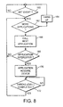
Figure 8 illustrates a sequence of events which will occur when a call is received
at the modem 30.
Step 160 in Figure 8 represents state 194 in Figure 7 at which the dispatcher
idles awaiting a call event from the modem device 30 or a request for use of the modem
from one of the applications 126, 128 and 130. When a call event from the modem
device 30 is detected, the dispatcher 124 refers to the stored characteristics of the
applications, including the allocated priority, to determine the application having the
highest priority. It then calls that application at step 166 to enquire from the application
whether it is interested in taking up the call concerned.
Figure 9 illustrates the basic steps involved in each application determining
whether or not it is interested in handling the call. Accordingly, with reference to Figure
9, on being notified of an incoming call, an application establishes at step 180 whether it
is able to handle the call. The test performed at step 180 will depend on the type of
application concerned. It can use the characteristics of the device which has been
allocated to it to determine whether it can take up the call. For example, if the device
concerned which has been allocated is not capable of voice-mode operation, then a voice
mail application would most likely decline to handle the call. However, in the case of
connection to the modem, the voicemail application would in principle be able to handle
the call.
Accordingly, if the application determines that it can attempt to handle a call, it
answers the call (if not already answered) and then must rapidly determine if the call is
for it or not. For example, if a voice application detects a fax calling tone, then it has
determined that the call is not for it. If an application decides that the call is not for it,
then it must exit as rapidly as possible and return control (188) to the dispatcher so that
the dispatcher can pass the call to another application for handling without handing up.
If, however, the application does decide to handle the call, it then requests that the
modem be allocated to it at step 182. If the modem is acquired, then the application
processes the call at step 184. On completion, the application hangs up at step 186 and
returns control at step 188 to the dispatcher 124. The applications 126, 128, 130, thus
form functional modules for handling different types of call.
Returning to Figure 8, step 168 corresponds to step 180 of Figure 9.
Accordingly, if an application is not interested in handling a call, control passes back to
the dispatcher to step 162 and the next application in the list of priorities is chosen. If,
however, the application does wish to handle the call, then the application makes a
request to acquire the device (step 182 of Figure 9), and, in this case it being assumed
that no other application has control of the device, the request will be granted. The
dispatcher then waits at step 190 (see Figure 7) for the application to terminate. In order
to ensure that termination of the application is captured, an embodiment of the invention
links the dispatcher to termination of the application by means of a Thread.join()
operation. The use of the Thread.join() operation will be described in more detail
below.
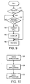
Through the use of the various priorities for the individual applications, the
dispatcher is able to guarantee that, as represented in Figure 10, a voice application 126
will be offered the chance to handle calls before a fax application 128, which in turn will
have a chance to handle calls before a data application 130. This enables an analog
telephony call discrimination mechanism to work effectively. In particular, in the case
of analog telephony, using modems, it is impossible to determine the type of an
incoming call without first answering the call and finding out what form the call is. It is,
moreover, desirable that a voice application is operable first as it would be disconcerting
to a voice caller to be presented by data tones instead of a voice service.
Accordingly, through the use of the priority method employed in an embodiment
of the present invention, a voice application first of all determines whether the incoming
call is a fax or a data call, this being determined by either the receipt of appropriate tones
supplied by the caller or by silence. The former is indicative of a fax call, and the latter
of a data call. If no tones are received but the call is not silent, then it is assumed to be a
voice call.
Where fax tones or silence is received, then the dispatcher gives a fax
application an opportunity to answer the call. A fax application is able to discriminate
between a fax and a data call, because a fax call will normally only generate the fax call
tone, whereas as a data call will be silent awaiting data tones from the receiver.
Accordingly, if a fax application determines that the incoming call is a fax call, it then
proceeds to handle that call.
If the incoming call is not a fax call, then control passes back to the dispatcher,
which then allocates the call to a data application for handling the call.
As mentioned above, there may be more than one voice application, more than
one fax application and more than one data application. In this case, the dispatcher
allocates a call in accordance with the individual priorities of the applications concerned.
The order is determined by controlling the priorities which are allocated to individual
applications so that the applications are then called in the appropriate sequence.
In the above, with reference to Figures 8, 9 and 10, a description has been given
of the processing of a call received via the modem device 30. It will be appreciated that
the process would be the same if received via the modem 32, with the exception that the
dispatcher 144 would be responsible for dispatching the tasks to the corresponding
instances of voice, fax and data applications 146, 148, 150.
Figure 11 is a description of the processing of a request from an application such
as one of the voice, fax and data applications 126, 128 and 130 to the dispatcher 124 to
use the modem device 30. It will be appreciated that a similar process is also involved
where one of the applications 146, 148 and 150 makes a request to the dispatcher 144
for use of the modem device 32.
Accordingly, with reference to Figure 11, an application requests the use of the
device at step 200. At step 202, the dispatcher checks whether the device is in use or
not. If the device is already in use, (i.e. the dispatcher is at state 190 illustrated in Figure
7) then the dispatcher 124 reports this back to the requesting application. Optionally a
hint indication may be provided at step 204 as to the time the device will remain in use,
thereby enabling the application to decide at step 206 whether to re-try the request at a
predetermined time in the future, or to abandon the request.
In an embodiment to the invention, the application requests the use of the device
by the dispatcher by calling an acquireDevice() primitive. The acquireDevice()
primitive indicates success or failure to the caller depending on whether the device is
currently free or not. In order to be able to return the hint, the acquireDevice() primitive
is arranged to return extra information about how long it believes the device will be
occupied for, so that the calling application can use this hint to implement an effective
retry policy.
There are a number of possible ways in which the dispatcher can determine how
long the device will be occupied.
In a simple form, this can be provided by heuristics based on an application type.
The dispatcher knows the basic type of each telephony application by virtue of the
priority number which is registered in the register storage 178 identified in Figure 5.
Accordingly, on the basis of the type of application currently owning the device, the
dispatcher is able to guess typical values of a call duration. For example, a typical
duration of a voice application (e.g. voicemail) is less than two minutes. A typical
duration of a fax application (transmission/reception) is of the order of one to five
minutes. A typical duration of a data application under a Point-to-Point Protocol (PPP)
is greater than ten minutes. It should be noted that these values are only given as
examples, and in any particular implementation, other values may be chosen. However,
the dispatcher is arranged to record the start time of an application and the type of
application so that when the acquireDevice primitive is called, the dispatcher can deduce
an estimated remaining time as the difference between the expected duration and the
time elapsed since the start time and can provide an indication of this with the
acquireDevice response to the calling application. The calling application can then use
this in step 206 to decide when to try again to obtain the device.
Alternatively, as represented in Figure 12, the dispatcher may provide an
additional step 203 of interrogating the current user application. This interrogation
could be by means of a re-entrant call, or could alternatively be by means of inspecting
attributes of the current user application is provided with suitable methods for giving an
indication of any further time it expects to continue to require the use of the device
allocated to it. It would, for example, often be the case that a fax application would be
able to give a relatively detailed estimate of the remaining time required in order to
finish the current job. This could be deduced from a transfer rate and a volume of fax
data still to be transmitted, for example.
It would also be possible for a combination of the heuristic and query
approaches described above. Accordingly, where a query is made to an application, and
the application is unable or does not provide any indication of the possible remaining
time it requires use of the device, then the hint could be based on the heuristic approach
described above.
As a result of providing hint information, it is possible for an application either
to choose to re-try at a later time, determined on the basis of the hint provided, or even
to abandon an attempt to re-try a request for use of the device.
Returning to Figure 11, if the device is currently not in use, then the dispatcher
will be idling in state 194 shown in Figure 7. Accordingly, in step 208, the dispatcher
marks the requesting application as the current user, and makes a "cancelGetEvent()"
call in step 210 in order to unblock the dispatcher in step 212. Control then passes (as
represented by loop 196 in Figure 7) to state 190 in Figure 7. In step 214, the dispatcher
detects the thread allocated to the user application and then waits for that thread to
terminate, by means of a join operation, for example a java.lang.Thread.join() operation
in a Java language environment. The dispatcher idles in step 216 until Thread.join()
completes at which point the dispatcher hangs up the call made by the application (if
this has not already been done by the application itself). A device.GetEvent() call is
made in step 220, whereby the dispatcher returns via edge 192 to the state 194
represented in Figure 7.
As mentioned above, with reference to Figures 8 and 11, a preferred
embodiment of the invention uses a Thread.join() method in order to detect the
termination of a thread. The Thread.join() method is a standard feature of the Java
programming environment. Other equivalent join functions may be provided in other
operating environments. This provides an effective and fully reliable solution to the
determination of when a thread terminates, and consequently an effective solution to the
management of a shared resource.
Classical solutions to resource management where a single entity provides
"acquire resource" and "release resource" primitives, involve would be users of the
resource asking the entity for access to the resource. In the situation where access to the
resource is granted, the request becomes the owner of the resource until such time as it
chooses to relinquish it by performing a "release resource" operation. During the period
of ownership, the owner of the resource has exclusive use of it. This scheme, although
widely used, has a major disadvantage in that, if a current resource owner fails and
exists due to a software or other error, then the resource may end up in a permanently
unavailable state because the current owner failed to perform a "release resource"
operation before finishing. The use of the join method avoids this problem in that the
resource management is provided by the Java language itself. Although specific
reference is made to a Java language, it will be appreciate that this technique is not
limited to the Java language, and can be provided in other language environments.
In essence, this resource management technique can be summarised as follows,
with reference to Figure 13. The resource manager (in the present case the dispatcher
124) provides the method "acquireDevice" which may be called by any application
wishing to use the resource in question (in the present case the telephony device (i.e. the
modem 30). Fundamental synchronisation primitives are then used to make sure that
only one caller can execute this method at a time, thereby guaranteeing exclusive access.
The would be owner calls the acquireDevice() primitive and identifies itself 231 to the
resource manager (here the dispatcher 124). In a Java programming environment it can
identify itself as an instance of Java.lang.Thread. It thus uses the unit of execution (i.e.
the thread) as the means of indicating ownership for the resource.
The resource manager (the dispatcher 124) then simply waits for the only
application thread 233 to finish execution before reclaiming control of the device. This
is achieved using language constructs in an entirely reliable way by the use of the join
method on the thread 233 which is currently the owner of the resource. If the owning
thread 233 exit normally or abnormally for whatever reason, fundamental language
synchronisation mechanisms allow the resource manager to determine that ownership
has been relinquished at step 234, enabling control to be passed 235 to the would be
owner to proceed as a new owning thread 236.
This arrangement effectively replaces a "release resource" primitive by a
language event that provides a fail safe solution to resource management. Such an
implication is simple to implement and is more robust than the use of a "release
resource" primitive. In particular, it is more robust as telephony applications requesting
use of a telephony resource (such as a modem device 30) are relatively complex and
potentially prone to failure. Also, such applications may be provided by third party
vendors whereby limited control over the quality of those applications is possible.
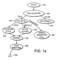
Figure 14 is a schematic illustration of part of one instance of a voicemail
application which could form an example of a voice application 126. The voicemail
application is implemented as a directed graph where each of the nodes in the graph
corresponds to a telephony component that performs a low level function of the
voicemail system. Such a low level component may be performing the functions of a
ring counter, detecting a caller ID, performing call filtering, answering a telephone call,
playing an audio prompt, reading DTMF signalling information, reading out a user's
messages, changing a voice prompt style, etc. Arcs, or links, between the nodes are
used to traverse from a given node to the next node in the graph depending on the results
of the operation in the given node.
The nodes are implemented by modules, preferably by objects, for performing
the operation at that node.
For example, in the illustrative example of Figure 14, a root node 240 provides
access to a ring counter module 242. The ring counter module determines whether a
predetermined number of rings are received (say 2, 3 or 4). If the result returned by the
module 242 is "false" (for example the caller hung up after the first ring) the false arc is
followed to a disconnect module 244 which performs the operations necessary to
disconnect the telephone call. If, however, the ring counter module returned a true value
(for example at least two rings were received), a "true" arc leads to a caller ID module
246 which looks to identify caller ID information supplied from the public switch
telephone network. If the caller ID identifies that the call is local (for example
corresponding to the country code in which the telecommunications device 10 is
located) control passes via the local arc to a standard style module 248 which sets up a
standard style for voicemail messages. For example, if the telecommunications device
10 is being used in France, the receipt of a French caller ID would cause a French
language style to be selected for answerphone functions. Alternatively, if the caller ID
was an international ID outside France, a default arc would be followed to a style setter
module 250 which could, for example, set up an English language style for the
answerphone functions. From either of the module 248 or the module 250, a respective
arc could be followed to an answer module 252 which then answers the telephone call.
Once the call is accepted (answered) control can pass via the following arc to a play
greeting module 254 which can play the greeting in the chosen style (French or English)
to the caller. The process can continue as represented at 256 to various more complex
voicemail functions (not shown).
Figure 14 also shows a further arc from the caller ID module 246. This arc
could be in response to identification of a call from one of a set of numbers (e.g. for
telesales companies) which causes a specific message to be played or the call to be
terminated, as represented schematically by the module "handle unwanted call" 258.
The caller ID module can maintain, or reference, a table of such unwanted numbers.
The caller ID module is thus able to provide call filtering with calls from selected
numbers being discarded or processed in a particular way. For example, the call can be
hung up even before ringing the user's telephone sounder.
It should be noted that in Figure 14, a directed graph structure is shown in that
control can pass from various modules to a common module, and indeed control can
pass back in a re-entrant manner to a previous or equivalent module (not shown).
In the present example, the modules are implemented as objects, in particular
language objects using the Java programming language. Such an object is represented
schematically in Figure 15. The object or module 260 implements an action 262 by
means of a method of that object. The result returned by the method is in the form of a
string 264 which identifies the link or arc to a successor object. Thus, in the example
shown in Figure 15, if the results returned are ABC, DEF, or GHI, these correspond to
labels respectively for an arc labelled ABC, DEF, or GHI, respectively. If the result is
other than one of the identified labels, then this is interpreted as leading to a default arc
labelled as such in Figure 15. It should be noted that although three letter
representations of the labels have been used in Figure 15, this does not indicate that the
string should be three letters, this being merely used for illustrative purposes.
The use of an object based structure of this type, enables a very flexible
definition of a call handling application such as a voicemail application. As telephony
services become more complex, individual users make more and more widely differing
demands on their voicemail systems. Some require complex voicemail systems with
specific welcoming messages to be sent out at specific times, and other users require
specific messages to be sent out depending on the identity or origin of the caller. Also,
the use of multiple mail boxes for different members of a family, or of a business, and
more complex functions can often be demanded by users. The use of a structure as
described above enables an extremely flexible definition of a voicemail system.
The directed graph object is defined as a serialised object which is accessible by
the operating system class loader (in the present instance a class loader found in the Java
environment). Serialisation is a feature of, for example, the Java language. A bean
object persists by having its properties, fields, and state information saved and restored
to and from storage. The mechanism that makes persistence possible is called
serialisation. When a bean instance is serialised, it is converted into a data stream and
written to storage. Any applet, application, or tool that uses that bean can then
"reconstitute" it by deserialisation. Seen in another way, object serialisation supports
the encoding of objects, and the objects reachable from them, into a stream of bytes; and
it supports the complementary reconstruction of the object graph from the stream. By
defining the graph object as a serialised object, it can be created externally or internally
to the telecommunications device and can be stored within the telecommunications
device, and called by the class loader when required.
Figure 16 illustrates an example where a plurality of different telephony controls
defining voicemail systems 270, 272, 274 are stored at a remote web server 118 and can
be displayed to the user of the telecommunications device 10 using a conventional web
browser. Using conventional techniques details and demonstrations of the individual
telephony controls can be supplied to the user by appropriate user actions.
Figure 16 illustrates a situation where the user has selected one of the telephony
controls having a desired voicemail functionality and a copy the serialised object 276
which is identified by a root node and defines the voicemail functionality is download
from a remote server 118 via the telecommunications network 110 (for example in
response to a simple drag and drop operation by the user) and stored on the hard disk
drive 50 within the telecommunications device 10. As the run-time behaviour of the
serialised object formed from a directed graph identified by a root node is not fixed by a
program, and because a class loader is used, the voicemail application is highly dynamic
and may come from anywhere, in particular, from the web over the telecommunications
network 110. This provides extreme flexibility to meet the varying customer
requirements as described above.
The flexibility provided facilitates the development and operation of call
answering functions within the telecommunications device to provide remote access to
messages, e-mails and faxes received and retained by the telecommunications device.
The call handling mechanism and/or the various applications and functional
modules may be provided in the form of a computer program product, that is computer
software, on a carrier medium. The carrier medium can be a magnetic or optical storage
device, or any other form of storage medium, or an wire, optical, wireless or satellite
telecommunications transmission medium, or any other suitable carrier medium..
Alternatively, or in addition, at least part of it may be embedded or hardwired in a
device such as an ASIC.
It will be appreciated that although particular embodiments of the invention have
been described, many modifications/additions and/or substitutions may be made within
the scope of the present invention.