TECHNICAL FIELD
The present invention relates to optical
transmission equipment, an optical repeater and optical
cross-connect equipment, and particularly to optical
transmission equipment, an optical repeater and optical
cross-connect equipment each having an optical amplifier
constructed by an optical fiber doped with Erbium, etc.
BACKGROUND ART
In a network constructed of a plurality of pieces of
node equipment electrically connected to one another
through optical fibers, optical transmission equipment each
having an optical amplifier constructed by an optical fiber
(hereinafter called "doped fiber") doped with Erbium, etc.
and a pumping light source are normally used inside the
respective node equipment. The optical transmission
equipment has the function of receiving a data optical
signal and a supervisory optical signal supplied from the
upstream side thereof, which are different in wavelength
from each other, amplifying the data optical signal and
outputting it to the downstream side thereof, or taking it
in the its own node equipment. Further, the optical
transmission equipment has the function of receiving the
supervisory optical signal and outputting a new supervisory
optical signal to the downstream side thereof, and
outputting a data optical signal on which data from within
its own node equipment is carried, to the downstream side
thereof. In order to achieve the functions described above,
the optical transmission equipment according to the related
art is constructed so as to have two light sources, i.e., a
pumping light source for pumping the doped fiber and a
light source for the supervisory optical signal.
The optical transmission equipment according to the
related art referred to above must be provided with two
types of light sources. Therefore, the optical
transmission equipment has a problem in that the number of
devices constituting the entire optical transmission
equipment increases and its configuration becomes complex.
DISCLOSURE OF INVENTION
An object of the present invention is to provide
optical transmission equipment, an optical repeater,
optical cross-connect equipment, node equipment and an
optical network capable of solving the problem of the
related art and which can be simplified in their device
configurations and constructed at low cost.
According to the present invention, the above-described
object is achieved by optical transmission
equipment comprising one or a plurality of doped fibers for
amplifying an input optical signal by a pumping light, and
an optical multiplexing device for multiplexing a
supervisory optical signal different in wavelength from the
data optical signal together with data optical signals
outputted from one or plural doped fibers referred to above
and outputting the multiplexed signal therefrom, and
wherein a pumping and supervisory light source shared for
the pumping light source and the light source of the
supervisory optical signal with respect to one or plural
doped fibers is provided.
Further, the above-described object is achieved by
providing an optical coupler for distributing light
outputted from the pumping and supervisory light source to
one or plural doped fibers and the optical multiplexing
device referred to above and thereby controlling the
pumping and supervisory light source so as to output light
modulated by supervisory information, or providing a
modulator for modulating light according to the supervisory
information between the optical coupler and the optical
multiplexing device and thereby controlling the pumping and
supervisory light source so as to output light indicative
of a constant output according to a direct current signal.
Moreover, the above-described object is achieved by
further providing an optical multiplexing device for
separating an input optical signal into a supervisory
optical signal and a data optical signal and a receiver for
the supervisory optical signal.
According to the present invention, the above-described
object is achieved by optical cross-connect
equipment comprising optical switches each having a
plurality of input terminals and output terminals for an
optical signal, and a controller for controlling the
optical switches and wherein the above-described optical
transmission equipment connected to the plurality of input
terminals of the optical switches and the plurality of
output terminals thereof respectively is provided, or a
plurality of data transmitters and a plurality of data
receivers connected to the plurality of input terminals of
the optical switches respectively are provided, thereby
controlling the optical switches, the data transmitters,
the data receivers and the plurality of pieces of optical
transmission equipment by the controller, or a pumping and
supervisory light source used for the doped fiber, which is
necessary for the optical transmission equipment is
provided in common to the plurality of pieces of optical
transmission equipment.
Further, the above-described object is achieved by
optical cross-connect equipment comprising an optical
circuit including a plurality of input terminals and output
terminals for optical signals, and a controller for
controlling the optical circuit and wherein the optical
circuit includes a wavelength multiplexing device, a
wavelength demultiplexing device, an optical amplifier, or
a regenerator other than the optical switches.
Moreover, the above-described object is achieved by
an optical network constructed by connecting a plurality of
pieces of node equipment through transmission lines using
optical fibers therebetween, wherein each of the plurality
of pieces of node equipment is constructed so as to have
the above-described optical cross-connect equipment and an
optical repeater including the above-mentioned optical
transmission equipment is provided midway of a transmission
line using optical fibers connecting between the respective
node equipment.
BRIEF DESCRIPTION OF DRAWINGS
Fig. 1 is a block diagram showing an example of a
basic configuration of optical transmission equipment
according to the present invention;
Fig. 2 is a block diagram illustrating another
example of a basic configuration of optical transmission
equipment according to the present invention;
Fig. 3 is a block diagram depicting a further
example of a basic configuration of optical transmission
equipment according to the present invention;
Fig. 4 is a block diagram showing a still further
example of a basic configuration of optical transmission
equipment according to the present invention;
Fig. 5 is a block diagram illustrating an example of
a configuration of optical transmission equipment according
to the present invention;
Fig. 6 is a block diagram depicting another example
of a configuration of optical transmission equipment
according to the present invention;
Fig. 7 is a block diagram showing a further example
of a configuration of optical transmission equipment
according to the present invention;
Fig. 8 is a block diagram illustrating a still
further example of a configuration of optical transmission
equipment according to the present invention;
Fig. 9 is a block diagram depicting an example of a
configuration of an optical repeater according to the
present invention;
Fig. 10 is a block diagram showing another example
of a configuration of an optical repeater according to the
present invention;
Fig. 11 is a diagram for describing an example of a
transmission system constructed by an optical repeater
according to the present invention;
Fig. 12 is a diagram for describing an example of
optical cross-connect equipment according to the present
invention;
Fig. 13 is a diagram for describing another example
of optical cross-connect equipment according to the present
invention;
Fig. 14 is a diagram for describing an example of a
configuration of an optical circuit of optical cross-connect
equipment according to the present invention;
Fig. 15 is a diagram for describing another example
of a configuration of an optical circuit of optical cross-connect
equipment according to the present invention;
Fig. 16 is a diagram for describing a further
example of a configuration of an optical circuit of optical
cross-connect equipment according to the present invention;
Fig. 17 is a diagram for describing a still further
example of a configuration of an optical circuit of optical
cross-connect equipment according to the present invention;
Fig. 18 is a diagram for describing a still further
example of a configuration of an optical circuit of optical
cross-connect equipment according to the present invention;
Fig. 19 is a diagram for describing a further
example of optical cross-connect equipment according to the
present invention;
Fig. 20 is a diagram for describing an example of a
configuration of a supervisory signal transmitter and
receiver of optical cross-connect equipment according to
the present invention;
Fig. 21 is a diagram for describing another example
of a configuration of a supervisory signal transmitter and
receiver of optical cross-connect equipment according to
the present invention;
Fig. 22 is a diagram for describing a further
example of a configuration of a supervisory signal
transmitter and receiver of optical cross-connect equipment
according to the present invention;
Fig. 23 is a diagram for describing a still further
example of a configuration of a supervisory signal
transmitter and receiver of optical cross-connect equipment
according to the present invention;
Fig. 24 is a diagram for describing a still further
example of a configuration of an optical circuit of optical
cross-connect equipment according to the present invention;
Fig. 25 is a diagram for describing a still further
example of optical cross-connect equipment according to the
present invention; and
Fig. 26 is a diagram showing an example of an
optical network constructed by pieces of node equipment
each of which is comprised of optical cross-connect
equipment according to the present invention.
BEST MODE FOR CARRYING OUT THE INVENTION
Preferred embodiments of optical transmission
equipment according to the present invention, an optical
repeater including the optical transmission equipment, and
an optical network using the optical repeater will
hereinafter be described in detail with reference to the
accompanying drawings.
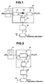
Fig. 1 is a block diagram showing a basic
configuration of a piece of optical transmission equipment
according to an embodiment of the present invention, and
Fig. 2 is a block diagram illustrating another example of a
basic configuration of a piece of optical transmission
equipment according to an embodiment of the present
invention, respectively. In Figs. 1 and 2, reference
numeral 11 indicates a doped fiber doped with Erbium, etc.,
reference numerals 12 and 14 indicate wavelength
multiplexing devices, reference numeral 13 indicates an
isolator, reference numeral 15 indicates an optical coupler,
reference numeral 16 indicates a light source for pumping
and supervision, reference numeral 17 indicates a driver,
and reference numeral 18 indicates a bi-directional
wavelength multiplexing device, respectively. Incidentally,
the optical transmission equipment according to the
embodiment of the present invention, which are shown in
Figs. 1 and 2, provide or exhibit only functions of
amplification and transmission of a data optical signal
inputted thereto and of transmission of a supervisory
optical signal. Further, the optical transmission
equipment can be utilized as a transmission-side apparatus
having data to be transmitted therefrom. While a
supervisory signal capturing or extracting function is
omitted herein, the present function can be added thereto
as the known component of apparatus.
The optical transmission equipment shown in Fig. 1
comprises the doped fiber 11 which amplifies a data optical
signal having a wavelength λd inputted from an optical
fiber on the upstream side in response to pumping light
inputted to the doped fiber 11, the wavelength multiplexing
device 12 which inputs the pumping light to the doped fiber
11, the optical isolator 13 which transmits the amplified
data optical signal sent from the wavelength multiplexing
device 12 in a predetermined direction, i.e., only in the
right direction in the case of the illustrated example, the
wavelength multiplexing device 14 which multiplexes the
amplified data optical signal and a supervisory optical
signal having a wavelength λp and outputs it to an optical
fiber on the downstream side, the light source 16 for
pumping and supervision, which emits a light of wavelength
λp for pumping and supervision, the optical coupler 15
which distributes the pumping and supervisory light emitted
from the light source 16 to the wavelength multiplexing
devices at a constant ratio of N : 1, and the driver 17
which is supplied with supervisory information and a direct
current signal so as to control the light source 16. While
the optical isolator 13 is placed between the wavelength
multiplexing devices 12 and 14 in the aforementioned
example of construction, it may be placed so as to differ
in position. Alternatively, the optical isolator 13 may be
omitted. Further, the wavelength multiplexing device 12,
the wavelength multiplexing device 14 and the optical
coupler 15 can be integrally formed as an optical circuit.
A feature of the optical transmission equipment
shown in Fig. 1 according to the embodiment of the present
invention resides in that only the pumping and supervisory
light source 16 provides the light source for pumping the
doped fiber 11 and the light source for the supervisory
information. Namely, the pumping and supervisory light
source 16 outputs a light of wavelength λp usable for the
light source for pumping the doped fiber 11 and the light
source for supervisory information. This light is divided
at the constant ratio N : 1 predetermined by the optical
coupler 15 in power thereof. The light divided at "N" of
the ratio is applied to the doped fiber 11 through the
wavelength multiplexing device 12 so as to pump up the
doped fiber 11. The light divided at "1" of the ratio is
inputted to the wavelength multiplexing device 14 as the
supervisory optical signal together with the amplified data
optical signal inputted through the isolator 13, followed
by multiplexing. Thereafter, the multiplexed signal is
outputted to the optical fiber on the downstream side.
Here, the "N" is a value determined by the ratio of the
power of pumping light necessary for the doped fiber and
that necessary for the supervisory optical signal. It may
generally range from 10 to several hundreds. As a matter
of course, the power of the light outputted from the
pumping and supervisory light source 16 needs more than the
sum of the power of the pumping light necessary for the
doped fiber and that necessary for the supervisory optical
signal.
Since the pumping and supervisory light source 16 is
controlled by the driver 17 which receives the direct
current signal DC and the supervisory information, the
light outputted therefrom results in one modulated by the
supervisory information and the power thereof results in
one controlled by the direct current signal DC. As
described above, part of the output light is inputted to
the wavelength multiplexing device 14 as the supervisory
optical signal together with the amplified data optical
signal inputted through the isolator 13, where they are
subjected to multiplexing, followed by output to the
optical fiber on the downstream side. Further, the
modulated part of light output is supplied to the doped
fiber 11 so as to pump the doped fiber. Since, however,
the supervisory information is low in bit rate, the doped
fiber 11 is pumped without being affected by the modulated
pumping light.
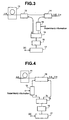
The optical transmission equipment shown in Fig. 2
according to the embodiment of the present invention is one
wherein a bi-directional wavelength multiplexing device 18
is provided as an alternative to the wavelength
multiplexing devices 12 and 14 and optical isolator 13
employed in the optical transmission equipment described
with reference to Fig. 1. Other portions are constructed
in a manner similar to those shown in Fig. 1. In the
optical transmission equipment according to the present
embodiment, the bi-directional wavelength multiplexing
device 18 supplies the output light produced from the
pumping and supervisory light source 16, which is divided
by the optical coupler 15, to the doped fiber 11 as the
pumping light. Further, the bi-directional wavelength
multiplexing device 18 outputs the amplified data optical
signal and the supervisory optical signal produced from the
pumping and supervisory light source 16, which is divided
by the optical coupler 15, to the optical fiber on the
downstream side.
According to the embodiments of the present
invention, which are shown in Figs. 1 and 2, the single
pumping and supervisory light source 16 can be shared for
the light source for pumping the doped fiber 11 and the
light source for the supervisory information, thereby
making it possible to simplify the construction of the
optical transmission equipment. While the data optical
signal is described as a signal of a single wavelength in
the configurations shown in Figs. 1 and 2, it may be a
signal of wavelength multiplexed.
Fig. 3 is a block diagram showing a basic
configuration of optical transmission equipment according
to a further embodiment of the present invention, and Fig.
4 is a block diagram showing another example of a basic
configuration of optical transmission equipment according
to an embodiment of the present invention, respectively.
In Figs. 3 and 4, reference numeral 19 indicates a
modulator, and other reference numerals are the same as
those shown in Figs. 1 and 2. Although the optical
transmission equipment described in Figs. 1 and 2 are
constructed so that the supervisory information is inputted
to the driver 17 for controlling the pumping and
supervisory light source 16 to modulate the output light
from the pumping and supervisory light source 16 according
to the supervisory information, the optical transmission
equipment according to the embodiments of the present
invention, which are shown in Figs. 3 and 4, are provided
with the modulator for the supervisory information
separately and operate in a manner similar to the optical
transmission equipment explained in Figs. 1 and 2.
The optical transmission equipment shown in Fig. 3
according to the embodiment of the present invention is
basically identical to the optical transmission equipment
shown in Fig. 1. However, the optical transmission
equipment shown in Fig. 3 is different from that shown in
Fig. 1 in that the modulator 19 for modulating the input
light according to the supervisory information is inserted
between the wavelength multiplexing device 14 for
multiplexing the amplified data optical signal (whose
wavelength is λd) and the supervisory optical signal and
outputting the multiplexed signal to the optical fiber on
the downstream side, and the optical coupler 15 for
distributing the output light produced from the light
source 16 at the constant ratio N : 1 for the purposes of
pumping and supervision. Thus, the driver 17 employed in
the present embodiment may simply control the power of the
output light of the pumping and supervisory light source 16,
based on the direct current signal DC. Although, however,
the optical isolator is not shown in Fig. 3, it can be also
provided in the same manner as in Fig. 1.
The optical transmission equipment shown in Fig. 4
according to the embodiment of the present invention is
basically identical to that shown in Fig. 2. However, the
optical transmission equipment shown in Fig. 4 is different
from that shown in Fig. 2 in that the modulator 19 for
modulating the input light according to the supervisory
information is inserted between the input terminal for the
supervisory optical signal of the bi-directional wavelength
multiplexing device 18 and the optical coupler 15 for
distributing the output light produced from the light
source 16 at the constant ratio N : 1 for the purposes of
pumping and supervision. Thus, even in the case of the
present embodiment, the driver 17 may simply control the
power of output light of the pumping and supervisory light
source 16, based on the direct current signal DC.
According to the embodiments of the present
invention, which are shown in Figs. 3 and 4, since the
pumping output light produced from the pumping and
supervisory light source 16 is not modulated, the pumping
and supervisory light source 16 can pump up the doped fiber
11 with pure pumping light. Further, even when the bit
rate of the supervisory information increases, the pumping
and supervisory light source 16 can pump up the doped fiber
11 with certainty. Although the data optical signal is
described as a signal of a single wavelength in the
configurations shown in Figs. 3 and 4, the data optical
signal may be a wavelength multiplexed signal.
Fig. 5 is a block diagram showing a configuration of
optical transmission equipment according to an embodiment
of the present invention. In Fig. 5, reference numerals
11a through 11n indicate doped fibers, reference numerals
12a through 12n indicate wavelength multiplexing devices,
and reference numeral 20 indicates a star coupler,
respectively. Other reference numerals are the same as
those shown in Fig. 3. The embodiment of the present
invention shows an application of the embodiment shown in
Fig. 3 and is one in which the present invention is applied
to a piece of wavelength multiplexed type optical
transmission equipment.
The optical transmission equipment shown in Fig. 5
comprises the plurality of doped fibers 11a through 11n for
respectively amplifying a plurality of data optical signals
having wavelengths λd1 through λdn, the wavelength
multiplexing devices 12a through 12n provided so as to
correspond to the respective doped fibers 11a through 11n,
for respectively supplying pumping light to these doped
fibers 11a through 11n and transmitting the amplified data
optical signals, a wavelength multiplexing device 14 for
multiplexing the amplified data optical signals and a
supervisory optical signal of wavelength λp and outputting
the multiplexed signal to an optical fiber on the
downstream side, a modulator 19 for modulating input light
according to supervisory information and transmitting it to
the wavelength multiplexing device 14, a star coupler 20
for distributing light outputted from a pumping and
supervisory light source 16 to the wavelength multiplexing
devices 12a through 12n and the modulator 19, the pumping
and supervisory light source 16 for emitting the light of
wavelength λp for pumping and supervision, and a driver 17
supplied with a direct current signal DC so as to control
the power of the output light of the light source 16.
Although each of the data optical signals λd1
through λdn is explained as a signal of a single wavelength
in the configuration shown in Fig. 5, they may be
wavelength multiplexed signals respectively.
In the aforementioned embodiments shown in Figs. 1
through 5, when the doped fibers 11a through 11n are of
Erbium-doped fibers doped with Erbium, wavelengths of
light signals lying in a 1.48 µm-band or wavelengths of
light signals lying in a 0.98 µm-band are used as the
wavelengths λp of the pumping and supervisory optical
signals. In this case, wavelengths of light signals lying
within a 1.5 µm-band are used as the wavelengths of the
data optical signals λd1 through λdn.
In addition to the effects obtained by the
embodiment shown in Fig. 3, the embodiment shown in Fig. 5
according the present invention can obtain effects in that
the plurality of doped fibers can be pumped up by providing
one pumping and supervisory light source 16 alone, and the
light source can be shared for the supervisory information.
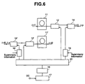
Fig. 6 is a block diagram showing another
configuration of the optical transmission equipment
according to the embodiment of the present invention. In
Fig. 6, reference numeral 11' indicates a doped fiber, and
reference numerals 12' and 14' indicate wavelength
multiplexing devices. Other reference numerals are the
same as those shown in Figs. 3 and 5. The embodiment of
the present invention shows an application of the
embodiment shown in Fig. 3 and is one in which the present
invention is applied to bi-directional optical transmission
equipment.
The optical transmission equipment shown in Fig. 6
is optical transmission equipment wherein data optical
signals of wavelengths λd1 and λd2 are respectively
transmitted in reverse directions through each independent
optical fiber. A portion for amplifying the data optical
signal of wavelength λd1 and relaying it, which is
comprised of the doped fiber 11, wavelength multiplexing
devices 12 and 14, and modulator 19, is completely the same
as that shown in Fig. 3 in configuration. The present
optical transmission equipment is different from that shown
in Fig. 3 in that there are provided the doped fiber 11',
wavelength multiplexing devices 12' and 14' and modulator
19' for amplifying the data optical signal of wavelength λ
d2 and relaying it in the opposite direction. The
embodiment of the present invention shown in Fig. 6 is
constructed so as to have a star coupler 20 for
distributing light outputted from a pumping and supervisory
light source 16 to the wavelength multiplexing devices 12
and 12' and modulators 19 and 19' in common with respect to
these, the pumping and supervisory light source 16 for
emitting light having wavelength λp for pumping and
supervision, and a driver 17 for controlling the power of
output light of the light source 16 according to the
application of a direct current signal DC.
In addition to the effects obtained by the
embodiment shown in Fig. 3, the embodiment shown in Fig. 6
according to the embodiment of the present invention can
obtain effects in that the two doped fibers for amplifying
the data optical signals to be transmitted in the
directions opposite to each other can be pumped up by
providing one pumping and supervisory light source 16 alone,
and the light source can be also shared for the supervisory
information.
Incidentally, the light signals of λd1 and λd2 may
be bi-directionally transmitted by a single optical fiber.
In such a case, it is necessary to add, on the left and
right side, i.e., both sides of the optical transmission
equipment shown in Fig. 6, devices which perform the
multiplexing and demultiplexing of the light signals of λd1
and λd2. While the data optical signal is described as a
signal having a single wavelength in the configuration
shown in Fig. 6, it may be a wavelength multiplexed signal.
The present embodiment can be applied even to the
optical transmission equipment of the wavelength
multiplexed type shown in Fig. 5. As a result, it can
construct a piece of bi-directional optical transmission
equipment of wavelength multiplexed type.
Fig. 7 is a block diagram showing a further
configuration of the optical transmission equipment
according to the embodiment of the present invention.
Reference numerals in the drawing are identical to those
shown in Fig. 3.
In the respective embodiments according to the
present invention, which have been described so far, the
data optical signal and the supervisory optical signal are
identical to each other in the direction of transmission.
However, the present embodiment according to the present
invention shows an example wherein the transmission
direction of the supervisory optical signal is set opposite
to that of the data optical signal.
The optical transmission equipment shown in Fig. 7
according to the embodiment of the present invention is
different from that shown in Fig. 3 in that a doped fiber
is provided on the output side of the data optical signal
and a modulator 19 for supervisory information is provided
between a wavelength multiplexing device 14 provided on the
input side and a coupler 15. The present optical
transmission equipment is constructed in the same as that
shown in Fig. 3 in other respects. Owing to such a
construction, the optical transmission equipment shown in
Fig. 7 can transmit the supervisory optical signal
modulated by the modulator 19 based on the supervisory
information in the direction opposite to that of
transmission of the data optical signal through the
wavelength multiplexing device 14.
Although the data optical signal is described as a
signal of a single wavelength in the configuration shown in
Fig. 7, it may be a wavelength multiplexed signal.
Fig. 8 is a block diagram illustrating a still
further configuration of the optical transmission equipment
according to the embodiment of the present invention.
Reference numerals in the drawing are identical to those
shown in Fig. 6. The present embodiment of this invention
makes it possible to pump up a doped fiber from both
directions thereof.
The optical transmission equipment shown in Fig. 8
according to the embodiment of the present invention is
completely the same as that shown in Fig. 3 in that a
portion for amplifying the data optical signal of
wavelength λd and relaying it, which is comprised of the
doped fiber 11, wavelength multiplexing devices 12 and 14,
and modulator 19, while it is different from that shown in
Fig. 3 in configuration, in that another wavelength
multiplexing device 12' is provided at a front stage of the
doped fiber 11, and an input data optical signal and
pumping light are inputted to the wavelength multiplexing
device 12'. The embodiment of the present invention shown
in Fig. 8 comprises a star coupler 20 for distributing
light outputted from a pumping and supervisory light source
16 to the wavelength multiplexing devices 12 and 12' and
modulator 19 in common with respect to these, the pumping
and supervisory light source 16 for emitting light having
wavelength λp for pumping and supervision, and a driver 17
for controlling the power of the output light of the light
source 16 according to the application of a direct current
signal DC.
According to such a construction, the doped fiber 11
is pumped up from both directions by the wavelength
multiplexing devices 12 and 12', so that a large optical
amplification factor or gain can be obtained. In the
present construction as well, the two doped fibers 11 can
be provided in series at positions shown in the drawing.
In this case, a further large optical amplification factor
or gain can be obtained.
According to the embodiment of the present invention
shown in Fig. 8, the provision of one pumping and
supervisory light source 16 alone allows the amplification
of the data optical signal with the large amplification
gain. It is also possible to obtain an effect that the
light source can be shared even for the supervisory
information.
Though the data optical signal is explained as a
signal of a single wavelength in the configuration shown in
Fig. 8, it may be a wavelength multiplexed signal.
The respective embodiments of the present invention
described so far have been explained as the optical
transmission equipment having only the function of
amplifying and transmitting the input data optical signal
and the function of transmitting the supervisory optical
signal. A description will next be made of embodiments of
optical repeaters each provided with the function of taking
in or extracting supervisory information from the
corresponding optical transmission equipment on the
upstream side with respect to the aforementioned optical
transmission equipment according to the respective
embodiments of the present invention.
Fig. 9 is a block diagram showing an example of a
configuration of an optical repeater according to another
embodiment of the present invention, and Fig. 10 is a block
diagram showing another configuration of the optical
repeater according to the embodiment of the present
invention, respectively. In Figs. 9 and 10, reference
numeral 11'' indicates a doped fiber, reference numeral 12''
indicates a wavelength multiplexing device, reference
numeral 91 indicates the optical transmission equipment
heretofore described by the embodiments, reference numeral
92 indicates a wavelength demultiplexing device, reference
numeral 93 indicates a supervisory information receiver,
reference numeral 94 indicates a controller, and reference
numeral 95 indicates a pumping light source, respectively.
The optical repeater shown in Fig. 9 according to
the embodiment of the present invention comprises, on the
input side of the optical transmission equipment 91 having
the configuration according to each of the embodiments of
the present invention explained by reference to Figs. 1
through 4 and Fig. 8, the doped fiber 11'', the wavelength
multiplexing device 12'' for inputting a data optical signal
and pumping light produced from the pumping light source 95
to the doped fiber, the wavelength demultiplexing device 92
for extracting a data optical signal of wavelength λd and
a supervisory optical signal of wavelength λp from an input
light signal, the supervisory information receiver 93 for
receiving the supervisory optical signal and converting it
into an electrical signal, followed by delivery to the
controller, and the controller 94 for controlling the
overall optical repeater. In the embodiment of the present
invention shown in Fig. 9, optical signals including a data
optical signal and a supervisory optical signal sent from
another unillustrated optical repeater which is connected
to the front stage, are divided into the data optical
signal and the supervisory optical signal by the wavelength
demultiplexing device 92. The supervisory optical signal
of wavelength λp is converted to the electrical signal by
the supervisory information receiver, which in turn is
inputted to the controller 94. Together with the pumping
light produced from the pumping light source 95 emitting
the light of wavelength λp, the data optical signal of
wavelength λd is supplied via the wavelength multiplexing
device 11 to the doped fiber 11, where it is amplified and
inputted to the optical transmission equipment 91. The
controller 94 for controlling the overall optical repeater
produces electrical supervisory information to be
transmitted to a back stage thereof on the basis of the
supervisory information outputted from the supervisory
information receiver 93 and transmits it to the optical
transmission equipment 91. As described above, the optical
transmission equipment 91 produces a supervisory optical
signal, based on the supervisory information sent from the
controller 94 and transmits it to the downstream side
together with the input data optical signal.
Although the pumping light source 95 for pumping the
doped fiber 11'' is provided in the example shown in Fig. 9,
it can be used in common with a pumping and supervisory
light source provided within the optical transmission
equipment 91. If the wiring is made as indicated by a
dotted line in Fig. 9, then the pumping light source 95 can
be omitted.
The optical repeater shown in Fig. 10 according to
the embodiment of the present invention is one in which the
doped fiber 11'', wavelength multiplexing device 12'' and
pumping light source 95 employed in the optical repeater
shown in Fig. 9 are deleted to thereby omit the
amplification function of the data optical signal therefrom.
This example is suitable for use in the case in which the
optical transmission equipment 91 is provided with the
doped fiber having sufficient gain. This can perform the
same function with a simple structure as compared with the
doped fiber shown in Fig. 9. According to the embodiments
shown in Figs. 9 and 10, a complete optical repeater having
the function of extracting the supervisory signal can be
simplified in configuration. Further, the data optical
signal may be a signal of a single wavelength or a
wavelength multiplexed signal in which a plurality of
wavelengths are multiplexed.
Although the optical transmission equipment having
the construction described by the embodiment of the present
invention shown in each of Figs. 1 through 4 and Fig. 8 is
used as the optical transmission equipment 91 in the
embodiments of the present invention shown in Figs. 9 and
10, the present invention can utilize the optical
transmission equipment according to the embodiments of the
present invention shown in Figs. 5 through 7 as the optical
transmission equipment 91 so as to construct the optical
transmission equipment of wavelength multiplexed type, the
optical transmission equipment of bi-directional type, and
the optical transmission equipment for transmitting the
supervisory optical signal in the direction opposite to
that of the data optical signal.
Fig. 11 is a diagram for describing an example of a
transmission system constructed by the optical repeaters
according to the embodiments of the present invention which
haven heretofore been described. In Fig. 11, reference
numeral 111 indicates optical transmission equipment of the
transmitting side, reference numeral 112 indicates a
controller, reference numerals 113 through 115 indicate
optical repeaters, and reference numeral 116 indicates
optical transmission equipment of the receiving side,
respectively.
In Fig. 11, the optical transmission equipment 111
of the transmitting side is provided at a data transmitting
end and supplied with a data optical signal from an
unillustrated data transmitter. Further, supervisory
information represented in the form of an electrical signal
is inputted to the optical transmission equipment 111 from
the controller 112. One of the pieces of optical
transmission equipment according to the embodiments of the
present invention, which are described with reference to
Figs. 1 through 4 and Fig. 8, for example, may be used as
the present optical transmission equipment 111 of the
transmitting side. The optical repeater 111 transmits an
optical signal obtained by amplifying the inputted data
optical signal and a supervisory optical signal modulated
according to the supervisory information from the
controller 112 to the optical transmission equipment 116 of
the receiving side through a transmission line composed of
optical fibers respectively having the optical repeaters
113 through 115. One of the optical repeaters according to
the embodiments of the present invention described in Figs.
9 and 10 may be used as the optical repeaters 113 through
115. Further, the equipment 116 of the receiving side
takes a construction excluding the optical transmission
equipment 91 of the optical repeater described in Fig. 9.
Light outputted from a doped fiber 11'' is connected to an
unillustrated data receiver. The equipment 116 of the
receiving side may take a configuration excluding the
optical transmission equipment 91 of the optical repeater
described in Fig. 10. While the data optical signal is
described as the signal of single wavelength in the
construction shown in Fig. 11, it may be a wavelength
multiplexed signal.
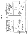
Fig. 12 is a diagram for describing an example of
optical cross-connect equipment constructed by the optical
repeaters according to the embodiments of the present
invention mentioned above. In Fig. 12, reference numerals
121-1 through 121-n and 122-1 through 122-n indicate
optical repeaters, reference numeral 123 indicates an
optical switch, and reference numeral 124 indicates a
controller, respectively.
The example of the optical cross-connect equipment
shown in Fig. 12 illustrates the optical cross-connect
equipment which incorporates therein the optical repeaters
according to the respective embodiments of the present
invention described above. The present optical cross-connect
equipment comprises the optical switch 123 having a
large number of optical switching elements and the function
of switching between optical signals so that each optical
signal is transmitted from any input terminal to any output
terminal, a plurality of the optical repeaters 121-1
through 121-n electrically connected to their corresponding
plural input terminals, a plurality of the optical
repeaters 122-1 through 122-n electrically connected to
their corresponding plural output terminals, and the
controller 124 for controlling the entirety of these.
Since it is constructed so as to have the large
number of optical switching elements thereinside, the
optical switch 123 causes an insertion loss of light.
Therefore, the plurality of optical repeaters 121-1 through
121-n electrically connected to their corresponding input
terminals of the optical switch 123 may preferably be
provided with an optical amplifying function respectively.
In the example shown in Fig. 12, the optical switch 123
takes a structure wherein the optical transmission
equipment 91 is omitted from the optical repeater described
with reference to Fig. 9. Further, lights outputted from
doped fibers 11'' are connected to the optical switch 123.
In the above-described construction, only one of pumping
light sources 59 contained in the plurality of optical
repeaters 121-1 through 121-n may be provided over all of
the optical repeaters 121-1 through 121-n and may be shared
between the optical repeaters 121-1 through 121-n. When
the data optical signals inputted to the optical repeaters
121-1 through 121-n are large in level, the optical
repeaters 121-1 through 121-n need not have the amplifying
function. In this case, as the optical repeaters 121-1
through 121-n may be used those each having a construction
excluding the optical transmission equipment 91 of the
optical repeater described with reference to Fig. 10.
In the example illustrated in Fig. 12, each of the
plurality of optical repeaters 122-1 through 122-n
connected to their corresponding output terminals of the
optical switch 123 makes use of the optical repeater
described with reference to Fig. 1. Further, the optical
transmission equipment described with reference to Figs. 2
through 4 and Fig. 8 can be used as these optical repeaters
122-1 through 122-n.
In the optical cross-connect equipment constructed
as described above, the controller 124 receives supervisory
information each divided from the optical signal inputted
to each optical repeater and converted into an electrical
signal, from the respective optical repeaters 121-1 through
121-n, and controls the optical switch 123 based on the
supervisory information or other control information
thereby to output the data optical signals outputted from
the optical repeaters 121-1 through 121-n to their
corresponding optical repeaters 122-1 through 122-n on the
output side. Further, the controller 124 effects necessary
processing on the received supervisory intonation and
distributes the respective supervisory information to the
optical repeaters 122-1, 122-n to transmit the supervisory
information, thereby controlling the corresponding pumping
and supervisory light sources 16 provided within the
respective optical repeaters.
When the respective optical transmission equipment
described with reference to Figs. 3, 4 and 8 are used as
the optical repeaters 122-1 through 122-n, the controller
124 may control the modulator 19 according to the
supervisory information. In this case, only one of the
pumping and supervisory light sources 16 provided in the
optical transmission equipment described with reference to
Figs. 3, 4 and 8 may be provided over all of the optical
repeaters 122-1 through 122-n and may be shared between the
optical repeaters 122-1 through 122-n. Further, the single
pumping and supervisory light source may be used in common
as the pumping light sources for the optical repeaters 121-1
through 121-n.
In the optical cross-connect equipment constructed
as described above, the optical switches and the large
number of optical repeaters contained thereinside can be
controlled by the single controller. Further, the single
light source can be shared for the pumping light source and
the light source for supervisory information although it
depends on the output power of the light source. Moreover,
the present light source can be shared between the large
number of optical repeaters. Thus, the equipment can be
constructed in small size and at low cost.
Although the data optical signal is explained as a
signal of a single wavelength in the construction shown in
Fig. 12, it may be a wavelength multiplexed signal.
When the data optical signal is given as the
wavelength multiplexed signal in Fig. 12, a wavelength
demultiplexer may be provided between the optical repeater
121 and the optical switch 123 and a wavelength multiplexer
may be provided between the optical switch 123 and the
optical repeater 122. Thus, the optical switch 123 can
realize switching in light units. Since, in this case, the
number of optical signals to be changed over increases, it
is necessary to construct the optical switch 123 on a large
scale.
Other optical cross-connect equipment according to
the present invention will next be described with reference
to Figs. 13 through 18. Fig. 13 is a diagram for
describing another example of the optical cross-connect
equipment constructed by using the optical repeaters
according to the embodiments of the present invention
explained so far. In Fig. 13, reference numerals 121-1'
through 121-n' and 122-1' through 122-n' indicate optical
repeaters, reference numerals 16' indicate supervisory
light sources, and reference numeral 125 indicates an
optical circuit including optical switches. Other
reference numerals are identical to those shown in Fig. 12.
Embodiments each illustrative of the optical circuit are
shown in Figs. 14 through 18.
In the optical cross-connect equipment described by
reference to Fig. 12, when the level of the data optical
signal inputted/outputted to and from each optical repeater
121 is large and the insertion loss of the optical switch
123 is small, the optical repeaters 122 need not have the
function of amplification. The optical cross-connect
equipment shown in Fig. 13 illustrates an example
constructed so that no amplifying function is provided in
the optical repeaters. Namely, the optical cross-connect
equipment shown in Fig. 13 comprises the optical repeaters
121-1' through 121-n' and 122-1' through 122-n' which have
no amplifying function. Each of the optical repeaters 121-1'
through 121-n' has the function of dividing or
demultiplexing and receiving the supervisory optical signal,
whereas each of the optical repeaters 122-1' through 122-n'
has the function of multiplexing and sending the
supervisory optical signal and the data optical signal.
Therefore, the light sources 16' included in the optical
repeaters 122-1' through 122-n' are respectively used only
as the supervisory light sources. Therefore, the
wavelength λs of the light source may be a wavelength
lying in a 1.3 µm band or 1.5 µm band (for example, at
1.51 µm) which shows less loss in the transmission line,
outside the band of the Erbium doped fiber. Alternatively,
the wavelength thereof may be a wavelength of 1.48 µm
which is the same as that of the pumping light source.
The supervisory optical signal sent from the
upstream side includes a control signal of the optical
circuit 125. Thus, the optical switches, optical
amplifiers, regenerators, etc. included in the optical
circuit can be controlled by the control signal. Similarly,
a control signal for cross-connect equipment on the
downstream side may be included in a supervisory optical
signal to be transmitted to the downstream side thereof.
Examples of the optical circuits applicable to the
optical cross-connect equipment shown in Fig. 13 are shown
in Figs. 14 through 18. The optical circuit 125-1 shown in
Fig. 14 is an optical matrix switch having a (mw + mr) × n
configuration. The optical circuit 125-1 switches WDM
signals collectively. For example, when mw pieces of
working fibers and mr pieces of restoration fibers are
connected to their corresponding input terminals of the
optical circuit 125-1, the optical circuit 125-1 changes
over transmission lines from the working fibers where
failures occur, to the normal restoration fibers under the
control of the controller 124 upon optical fiber cut or
optical cable cut, thereby making it possible to realize
the restoration from the failures.
Here, the optical switch used in the optical circuit
may be a blocking type or non-blocking type. Further, the
number of the inputs of the optical circuit and the number
of the outputs thereof may be identical to each other or
different from each other. Furthermore, while the WDM
signal is described as a uni-directional one in the above-described
example, it may be a uni-wavelength signal or a
bi-directional signal.
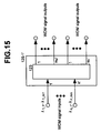
The optical circuit 125-1' shown in Fig. 15 is an
optical matrix switch having a n' × (nw' + mr')
configuration. The optical circuit 125-1' switches WDM
signals collectively. For example, when mw' pieces of
working fibers and mr' pieces of restoration fibers are
connected to their corresponding output terminals of the
optical circuit 125-1', the optical circuit 125-1' changes
over transmission lines from the working fibers where
failures occur, to the normal restoration fibers under the
control of the controller 124 upon optical fiber cut or
optical cable cut, thereby making it possible to realize
the restoration from the failures.
Here, the optical switch used in the optical circuit
may be a blocking type or non-blocking type. Further, the
number of the inputs of the optical circuit and the number
of the outputs thereof may be identical to each other or
different from each other. Furthermore, while the WDM
signal is described as a uni-directional one in the above-described
example, it may be a uni-wavelength signal or a
bi-directional signal.
The optical circuit 125-2-1 shown in Fig. 16
comprises a wavelength demultiplexing circuit 201, an
optical switch 123 having a (m1 + ... + mn) × (m1' + mn')
configuration, and a wavelength multiplexing circuit 202.
The optical circuit 125-2-1 wavelength-demultiplexes the
input WDM signals and performs switching every individual
wavelengths. Further, the optical circuit 125-2-1 performs
wavelength multiplexing so as to produce each output. This
has the function of performing routing for each wavelength.
While the wavelength demultiplexing of the WDM signals is
shared by a plurality of the wavelength multiplexing
circuits 201 and 202, it may be shared by one wavelength
demultiplexing circuit 201 and one wavelength multiplexing
circuit 202. Here, the optical switch 123 is controlled by
the controller 124 shown in Fig. 13.
The optical switch employed in the optical circuit
may be a blocking type or non-blocking type. Further, the
number of the inputs of the optical circuit and the number
of the outputs thereof may be identical to each other or
different from each other. Furthermore, while the WDM
signal is described as a uni-directional one in the above-described
example, it may be a uni-wavelength signal or a
bi-directional signal.
The optical circuit 125-2-2 shown in Fig. 17 is one
in which the optical circuit 125-2-1 shown in Fig. 16 is
improved and it is applicable to long-distance optical
fiber transmission. Therefore, regenerators 205 or optical
amplifiers 204 for each individual wavelengths are inserted
between the wavelength demultiplexing circuit 201 and the
optical switch 123 having the (m1 + ... + mn) × (m1' + mn')
configuration or between the optical switch 123 and the
wavelength multiplexing circuit 202. Further, an optical
amplifier 203 for each WDM signal is inserted at the front
stage of the wavelength demultiplexing circuit 201 or at
the back stage of the wavelength multiplexing circuit 202.
A wavelength outputted from each regenerator 205 may
be either of being variable or fixed. Further, it may be
the same as that of the input wavelength or different
therefrom. The optical fibers 203 and 204 are controlled
in output power according to a change in the bit rate of
the optical signal. Here, the optical switch 123,
regenerators 205, and optical amplifiers 203 and 204 are
controllable by the controller 124 shown in Fig. 13.
The optical switch employed in the optical circuit
may be a blocking type or non-blocking type. Further, the
number of the inputs of the optical circuit and the number
of the outputs thereof may be identical to each other or
different from each other. Furthermore, while the WDM
signal is described as a uni-directional one in the above-described
example, it may be a uni-wavelength signal or a
bi-directional signal.
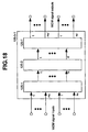
Fig. 18 shows the other embodiment of the optical
circuit. The optical circuit 125-3-1 comprises a
combination of an optical circuit 125-1, an optical circuit
125-2 (-1 or -2) and an optical circuit 125-1'. With its
construction, the switching in units of WDM signals by the
optical circuit 125-1 is performed on the WDM signal inputs.
Next, the switching in units of individual wavelengths is
effected by the optical circuit 125-2-1 or 125-2-2.
Finally, the change-over in units of the WDM signals is
performed by the optical circuit 125-1', followed by
execution of the transmission of each output.
According to the optical circuit 125-3-1, the
functions of the optical circuit 125-1, the optical circuit
125-2 and the optical circuit 125-1' can be implemented
simultaneously. Namely, the restoration from failures such
as optical fiber cut or optical cable cut, etc., and the
routing in wavelength units can be realized.
The operation of the optical circuit 125-3-1 is
controllable by the controller shown in Fig. 13.
Other embodiments of the cross-connect equipment of
the present invention will be described with reference to
Figs. 19 through 24. Fig. 19 is a diagram for describing
the other example of the bi-directional cross-connect
equipment constructed by each optical repeater according to
the embodiment of the present invention described
heretofore. In Fig. 19, respective supervisory optical
signal transmitters/receivers 126-1 through 126-n and 126-1'
through 126-n' extract, by the wavelength demultiplexing,
the wavelengths of supervisory optical signals from optical
signals inputted from optical fibers, respectively and
insert the supervisory optical signals into the optical
signals to be transmitted to the corresponding optical
fibers by the wavelength multiplexing.
Figs. 20 and 21 are respectively diagrams showing
the configurations of the respective supervisory optical
signal transmitter/receiver 126 and 126'. A signal sent
from the corresponding optical fiber passes through a
wavelength multiplexer/demultiplexer 127 and a supervisory
optical signal is separated or demultiplexed from the
signal by the corresponding optical repeater 121. The
supervisory optical signal is converted to a supervisory
electrical signal, followed by transmission to the
controller 124. Conversely, a signal from the
corresponding optical switch passes through the wavelength
multiplexer/demultiplexer 127. Thereafter, the optical
repeater 122 multiplexes a supervisory optical signal
converted into a supervisory electrical signal sent from
the controller 124 and sends it out to the corresponding
optical fiber. Incidentally, as shown in Figs. 22 and 23,
such constructions as to omit the respective wavelength
multiplexer/demultiplexer 127 from Figs. 20 and 21 are also
possible. In this case, it is apparent from Fig. 22 and 23
that the sequence of the optical repeaters 121-1', 122-1',
and 121-2', 122-2' may be set in reverse.
Wavelengths λs and λs' of light sources included in
the optical repeaters 122 may be wavelengths lying in a 1.3
µm band or 1.5 µm band (for example, at 1.51 µm) which
shows less loss in the transmission line, outside the band
of an Erbium doped fiber. Alternatively, each wavelength
thereof may be a wavelength lying within the band of the
Erbium doped fiber. Further, each wavelength may be a
wavelength of 1.48 µm which is the same as that of the
pumping light source.
In Fig. 19, reference numeral 125 indicates an
optical circuit including optical switches. Other
reference numerals are identical to those shown in Fig. 13.
The supervisory optical signal sent from the
upstream side includes a control signal of the optical
circuit 125. The optical switch, optical amplifier,
regenerator, etc. included in the optical circuit can be
controlled by the control signal. Similarly, the control
signal for the optical cross-connect equipment on the
downstream side may be included in the supervisory optical
signal to be transmitted to the downstream side thereof.
It is apparent from the reversibility of light that
the example of the optical circuit applicable to the
optical cross-connect equipment shown in Fig. 19 may be any
one of the optical circuits shown in Figs. 14 through 16.
One example thereof is shown in Fig. 24 illustrative of an
example of an optical circuit in which the uni-directional
optical circuit shown in Fig. 18 is bi-directionally used.
In Fig. 24, the optical circuit 125-3-2 comprises a
combination of an optical circuit 125-1, an optical circuit
125-2 (-1 or -2) and an optical circuit 125-1'. With its
construction, the switching in units of WDM signals by the
optical circuit 125-1 is performed on WDM signal inputs.
Next, the switching in units of individual wavelengths is
effected by the optical circuit 125-2-1 or 125-2-2.
Finally, the change-over in units of the WDM signals is
performed by the optical circuit 125-1', followed by
execution of the transmission of each output.
According to the optical circuit 125-3-2, the
functions of the optical circuit 125-1, the optical circuit
125-2 and the optical circuit 125-1' can be implemented
simultaneously. Namely, the restoration from failures such
as optical fiber cut or optical cable cut, etc., and the
routing in wavelength units can be realized.
The operation of the optical circuit 125-3-2 is
controllable by the controller shown in Fig. 19. The
optical switch employed in each optical circuit may be a
blocking type or non-blocking type. Further, the number of
the inputs of each optical circuit and the number of the
outputs thereof may be identical to each other or different
from each other.
Although the reference numeral 125-3-2 is affixed to
the optical circuit for its description, the optical
circuit 125-3-2 is basically identical to the optical
circuit 125-3-1 shown in Fig. 18. On the contrary, this
means that the optical circuits shown in Figs. 14 through
16 can be used bi-directionally.
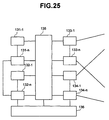
Fig. 25 is a diagram for describing a further
example of the optical cross-connect equipment constructed
by using the respective optical transmission equipment
according to the embodiments of the present invention which
have been described so far. In Fig. 25, reference numerals
131-1 through 131-n indicate data transmitters, reference
numerals 132-1 through 132-n indicate data receivers,
reference numerals 133-1 through 133-n and reference
numerals 134-1 through 134-n indicate optical transmission
equipment, reference numeral 135 indicates an optical
switch, and reference numeral 136 indicates a controller,
respectively.
The example of the optical cross-connect equipment
shown in Fig. 25 shows a piece of optical cross-connect
equipment in which the optical transmission equipment
according to the respective embodiments of the present
invention described above, the data transmitters and the
data receivers are incorporated therein. The optical
cross-connect equipment comprises the optical switch 135
having functions similar to those described by reference to
Fig. 12, a plurality of the data transmitters 131-1 through
131-n electrically connected to their corresponding plural
input terminals of the optical switch 135, the data
receivers 132-1 through 132-n electrically connected
thereto, a plurality of pieces of the optical transmission
equipment 133-1 through 133-n and 134-1 through 134-n
electrically connected to their corresponding plural output
terminals, and the controller 136 for controlling these
over their entirety.
The plurality of pieces of optical transmission
equipment 133-1 through 133-n electrically connected to the
output terminals of the optical switch 135 are used as
those for transmitting data optical signals and supervisory
optical signals. Further, one of the pieces of optical
transmission equipment explained by reference to Figs. 1
through 4 and Fig. 8 is used for them. Moreover, the
plurality of pieces of optical transmission equipment 134-1
through 134-n electrically connected to the output
terminals of the optical switch 135 are used as those for
receiving the data optical signals and the supervisory
optical signals. Those constructed except for the optical
transmission equipment 91 of the optical repeaters
described with reference to Figs. 9 and 10 are used for
them. Incidentally, the data transmitters 131-1 through
131-n and the data receivers 132-1 through 132-n may be
directly coupled so as to be used as the repeater in the
above description. An example in which the data
transmitter 131-n and the data receiver 132-n are directly
connected to each other, is illustrated in Fig. 25 by a
broken line. Further, the respective optical transmission
equipment 133-1 through 133-n may be replaced by the
respective optical transmission equipment 122-1' through
122-n' shown in Fig. 13 respectively. Similarly, the
respective optical transmission equipment 134-1 through
134-n may be replaced by the optical transmission equipment
121-1' through 121-n' shown in Fig. 13, respectively.
Furthermore, the data transmitter and the data
receiver may be different in transmission bit rate,
respectively. The controller 136 is capable of controlling
the output power level and gain of each optical
transmission equipment according to the transmission bit
rate.
In the optical cross-connect equipment constructed
as described above, the optical switches, the large number
of optical transmission equipment, the data transmitters
and the data receivers included thereinside can be
controlled by one controller, one light source can be
shared as for the pumping light source and the supervisory
information light source which are necessary for the
optical transmission equipment, and the large number of
optical transmission equipment can share the use of this
light source. Therefore, the equipment can be constructed
in a small size and at low cost.
Although the data optical signal is described as a
signal of a single wavelength in the construction shown in
Fig. 25, it may be a wavelength multiplexed signal.
The respective optical cross-connect equipment shown
in Figs. 12, 13, 19 and 25 are extremely suitable for use
in the construction of the node equipment of the optical
network constructed by connecting the plurality of pieces
of node equipment to one another through the optical fibers.
Incidentally, various ones have been already known as
specific configurations of the node equipment which makes
use of the optical cross-connect equipment.
Fig. 26 is a diagram showing an example of an
optical network constructed by means of the optical
repeaters according to the embodiments of the present
invention described heretofore, and the respective node
equipment which are constructed using the optical cross-connect
equipment constructed by using the optical
repeaters. In Fig. 26, N1 through N5 indicate the node
equipment respectively. The optical network shown in Fig.
26 is constructed so that a plurality of pieces of the node
equipment N1 through N5 are connected to one another in a
net-like manner by a plurality of optical fibers for bi-directionally
transmitting signals. In general, the signal
can be transmitted over a distance of about 70 km through
the optical fiber without providing an optical relay
amplifier midway of the optical fiber. It is however
necessary to provide the optical relay amplifier when the
distance between the respective node equipment reaches
greater than the above distance. In the example shown in
Fig. 26, the optical relay amplifiers indicated by marks Δ
are suitably provided midway of the optical fibers.
Each of the respective node equipment N1 through N5
placed within the network comprises each of the optical
cross-connect equipment described with reference to Figs.
12, 13, 19 and 25. Further, one of the respective optical
transmission equipment explained with reference to Figs. 1
through 4 and Figs. 8 through 10 can be used as the optical
relay amplifiers provided midway of the optical fibers used
as the transmission line. As the optical relay amplifiers
can be also used those each having a construction excluding
the optical transmission equipment 91 of the optical
repeaters described with reference to Figs. 9 and 10. As
the optical relay amplifiers midway of the optical fibers
used as the transmission line, can be also used an optical
relay amplifier described in U.S. Patent No. 5,500,756.
Further, the optical transmission equipment explained with
reference to Fig. 6 can be also used as the optical relay
amplifier with one-by-one optical fibers for transmitting a
signal in the opposite directions as a set.
The above-described network can be constructed at
low cost over its entirety by using the respective optical
transmission equipment according to the respective
embodiments of the present invention, the optical repeaters
including the optical transmission equipment, and the
optical cross-connect equipment using these optical
repeaters.
In the same manner as mentioned in the descriptions
of Figs. 1 through 13 and Fig. 25, each data optical signal
may be a signal of a single wavelength or a wavelength
multiplexed signal in the construction shown in Fig. 26.
According to the present invention, as has been
described above, one pumping and supervisory light source
can be shared for the light source for pumping the doped
fibers in each optical transmission equipment and the light
source for supervisory information, thereby making it
possible to simplify the construction of the optical
repeater including the optical transmission equipment.
According to the present invention, when the plurality of
pieces of optical transmission equipment are used or the
plurality of doped fibers are provided within one optical
transmission equipment, an effect can be obtained that the
plurality of doped fibers can be pumped up by providing
only one pumping and supervisory light source, and this
light source can be also used for the supervisory
information.
The construction of the optical cross-connect
equipment by the use of optical transmission equipment
according to the present invention makes it possible to
control the optical switches and the large number of
optical transmission equipment included thereinside by one
controller. Further, since one light source can be used in
common as the pumping light source and the supervisory
information light source and the large number of optical
transmission equipment can share the use of this light
source, the equipment can be constructed in a small size
and at low cost.
Further, the respective optical transmission
equipment according to the present invention and the node
equipment provided with the optical cross-connect equipment
using the pieces of optical transmission equipment
according to the present invention are used so as to
configure the optical network, whereby the entire optical
network can be constructed at low cost.