EP0965444A1 - A system and method for offset lithographic printing utilizing a reusable plate - Google Patents
A system and method for offset lithographic printing utilizing a reusable plate Download PDFInfo
- Publication number
- EP0965444A1 EP0965444A1 EP99303932A EP99303932A EP0965444A1 EP 0965444 A1 EP0965444 A1 EP 0965444A1 EP 99303932 A EP99303932 A EP 99303932A EP 99303932 A EP99303932 A EP 99303932A EP 0965444 A1 EP0965444 A1 EP 0965444A1
- Authority
- EP
- European Patent Office
- Prior art keywords
- printing
- image
- plate
- medium
- fluid
- Prior art date
- Legal status (The legal status is an assumption and is not a legal conclusion. Google has not performed a legal analysis and makes no representation as to the accuracy of the status listed.)
- Withdrawn
Links
Images


Classifications
-
- C—CHEMISTRY; METALLURGY
- C09—DYES; PAINTS; POLISHES; NATURAL RESINS; ADHESIVES; COMPOSITIONS NOT OTHERWISE PROVIDED FOR; APPLICATIONS OF MATERIALS NOT OTHERWISE PROVIDED FOR
- C09D—COATING COMPOSITIONS, e.g. PAINTS, VARNISHES OR LACQUERS; FILLING PASTES; CHEMICAL PAINT OR INK REMOVERS; INKS; CORRECTING FLUIDS; WOODSTAINS; PASTES OR SOLIDS FOR COLOURING OR PRINTING; USE OF MATERIALS THEREFOR
- C09D11/00—Inks
- C09D11/30—Inkjet printing inks
- C09D11/36—Inkjet printing inks based on non-aqueous solvents
-
- B—PERFORMING OPERATIONS; TRANSPORTING
- B41—PRINTING; LINING MACHINES; TYPEWRITERS; STAMPS
- B41M—PRINTING, DUPLICATING, MARKING, OR COPYING PROCESSES; COLOUR PRINTING
- B41M1/00—Inking and printing with a printer's forme
- B41M1/06—Lithographic printing
-
- B—PERFORMING OPERATIONS; TRANSPORTING
- B41—PRINTING; LINING MACHINES; TYPEWRITERS; STAMPS
- B41N—PRINTING PLATES OR FOILS; MATERIALS FOR SURFACES USED IN PRINTING MACHINES FOR PRINTING, INKING, DAMPING, OR THE LIKE; PREPARING SUCH SURFACES FOR USE AND CONSERVING THEM
- B41N3/00—Preparing for use and conserving printing surfaces
- B41N3/006—Cleaning, washing, rinsing or reclaiming of printing formes other than intaglio formes
-
- C—CHEMISTRY; METALLURGY
- C09—DYES; PAINTS; POLISHES; NATURAL RESINS; ADHESIVES; COMPOSITIONS NOT OTHERWISE PROVIDED FOR; APPLICATIONS OF MATERIALS NOT OTHERWISE PROVIDED FOR
- C09D—COATING COMPOSITIONS, e.g. PAINTS, VARNISHES OR LACQUERS; FILLING PASTES; CHEMICAL PAINT OR INK REMOVERS; INKS; CORRECTING FLUIDS; WOODSTAINS; PASTES OR SOLIDS FOR COLOURING OR PRINTING; USE OF MATERIALS THEREFOR
- C09D10/00—Correcting fluids, e.g. fluid media for correction of typographical errors by coating
-
- B—PERFORMING OPERATIONS; TRANSPORTING
- B41—PRINTING; LINING MACHINES; TYPEWRITERS; STAMPS
- B41C—PROCESSES FOR THE MANUFACTURE OR REPRODUCTION OF PRINTING SURFACES
- B41C1/00—Forme preparation
- B41C1/14—Forme preparation for stencil-printing or silk-screen printing
- B41C1/147—Forme preparation for stencil-printing or silk-screen printing by imagewise deposition of a liquid, e.g. from an ink jet; Chemical perforation by the hardening or solubilizing of the ink impervious coating or sheet
Definitions
- the present invention relates to offset lithographic printing utilizing a reusable plate.
- the plate contains one or more coating layers applied to a metal or plastic substrate layer.
- the cost of producing a plate is relatively expensive and is generally only economical when utilized for printing large numbers of copies. For short printing runs, the cost of using a printing plate and mounting it on the press adds substantially to the cost per printed copy.
- image once print many utilizes a master plate which is imaged on the press, then used to generate
- US Patent No. 4,833,486 to Zerillo describes lithographic apparatus for which utilizes an ink-jet image to the transfer an image on to a plate.
- US Patent No. 5,738,013 to Kellett describes another method of using ink-jet to produce a permanent printing plate.
- each plate that is prepared needs to be separately fitted on to the machine.
- each of the four plates (one for each color) needs to be skillfully fitted in turn on to the offset printing cylinders. Consequently, the preparation of a four-color printing job takes four times as long.
- a further disadvantage of existing systems is that any correction or change to a prepared plate requires manual correction by a skilled operator in order to avoid scratching or otherwise damaging the plate.
- An object of the present invention is to provide an improved imaging system for use in lithographic offset printing which overcome the disadvantages of prior methods.
- a further object of the present invention is to provide a system and method for erasing an imaged plate allowing it to be reused for a subsequent offset printing run.
- an offset lithographic printing system which includes an image bearing medium, forming part of the printing cylinder, liquid ejection means for forming an printing image in a pre-determined pattern directly on to an image bearing medium, means for printing the formed image onto a substrate in a conventional offset printing process, and a liquid ejection means connected to a source of erasing fluid.
- the liquid ejection means eject droplets of the erasing fluid on to the image bearing medium to release the pre-determined pattern, thereby allowing a subsequent image to be formed on to the image bearing medium.
- the system further includes a cleaning system to remove the released pattern.
- the image bearing substrate is aluminum with a grained anodized surface.
- the liquid ejection means includes an ink-jet print head connected to an fluid supply.
- the fluid supply consists of a solvent, an organic binder, a sensitive diazo compound and a dye colorant.
- the solvent is 1-methoxy-2-propanol,
- the correcting fluid consists of a solvent, gamma butyrolactone, a mixture of polyacrylic and phosphoric acid and a surface active agent.
- a method for erasing a previously imaged and inked plate and preparing the plate for re-imaging includes the steps of:
- the step of releasing includes spraying droplets of a correcting fluid on to the imaged plate.
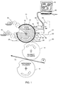
- Fig. 1 is a schematic illustration of the printing system, generally designated 10, constructed and operative in accordance with a preferred embodiment of the present invention.
- Fig. 2 is an illustration of the printing and erasing heads, 52 and 62, respectively, used in printing system 10.
- the printing system 10 comprises a plate cylinder 12 onto which is fitted a plate 22, a blanket cylinder 14, an impression cylinder 16, inking rollers 18, dampening rollers 20, a heater 26 and vacuum suction unit 28, all of which are conventionally used in lithographic printing systems.
- printing system 10 further comprises an cleaning unit, generally designated 30 and a computer unit, generally designated 40 coupled to an imaging system, generally designated 50.
- the printing system 10 further comprises an erasing system, generally designated 60, which is coupled to computer unit 40.
- Erasing system 60 erases the existing image on the plate 22 and in combination with cleaning unit 30 ensures that the plate can be reused for subsequent re-imaging.
- the erasing system 60 can be utilized for making changes or corrections to the plate 22 without the necessity of an operator directly coming into contact with the plate 22.
- the computer unit 40 comprises conventional processing units (not shown) allowing for an image to be created and displayed on a screen 42.
- the imaging data is transferred to the imaging system 50 and erasing system 60 by known in the art communications technology.
- the commands to erase the image or correct the image are passed by computer 40 to the erasing system 60 for erasing and correcting the image, respectively.
- the plate 22 may be in the form of an independent sheet that is attached to the plate cylinder 12 either by means of a clamping system or bonded to the surface of cylinder 12. It can be integral to the cylinder 12 or it may also be in the form of a sleeve that fits onto the cylinder 12.
- the material of the plate 22 is preferably aluminum with a grained anodized surface. Such surfaces are well known in the art as they are used in the manufacture of conventional pre-sensitized offset lithographic plates. The surfaces are designed to have excellent hydrophilic properties and to be hard wearing. Although such anodized aluminum is available to the industry, in order to illustrate this invention, a pre-sensitized plate was processed to provide the plate described as 22.
- the plate used by way of example was the "Electra” plate manufactured by Horsell, U.K.
- the plate was passed through an offset lithographic plate processor containing the processing solution supplied and recommended by Horsell as suitable for processing the "Electra” plate.
- the solution removed the entire blue pre-sensitized coating from the plate, leaving a clean grained anodized aluminum surface for use in the invention, as described.
- Imaging system 50 may be any suitable imaging system including, for example, an ink-jet system, such as described in EP Patent No. 94305347 to Karlinski, assigned to the present Applicants and incorporated herein by reference.
- the imaging system 50 utilizes an ink-jet imaging print head 52 connected to an "ink” supply 54, for imparting the image by ejecting "ink” droplets 53 onto the plate.
- the "ink” material 53 is a liquid suitable for application by ink-jet print heads.
- Such materials are available and sold as “Addition” fluids for correcting flaws in standard offset plates.
- An example of such a material is the material used in the "Addition pen” for offset plates” sold by Plurimetal s.r.l of Verona, Italy.
- This material comprises a solvent, such as 1-methoxy-2-propanol, an organic binder, a sensitive diazo compound and a dye colorant. Viscosity of such a fluid can be finely adjusted to suit the ink-jet head by further addition of the 1-methoxy-2-propanol solvent.
- the "addition" fluid when applied, renders the plate 22 oleophillic.
- the erasing system 60 which is described in further detail below with reference to Fig. 3, comprises a "correcting" (or “wipe out") print head 62 connected to a container of "correcting" fluid 64.
- the "correcting" print head 62 is any suitable device for controlled ejection of fluid, such as the device used for the imaging print head 52.
- the "correcting" liquid which is the negative of the "addition” material used for imaging, is specifically intended for correction of offset printing plates, such as plate 22.
- the “correcting” liquid is used by printers for correcting scratches or other defects on imaged and chemically processed plates in a conventional offset print process, and is available in liquid form or as a "pen”.
- the "correcting" liquid is commercially available from PluriMetal srl of Verona, Italy and identified by its commercial name of "Posigamma 12".
- This correcting material consists of a solvent, gamma butyrolactone, a mixture of polyacrylic and phosphoric acid and a surface active agent.
- the "correction" fluid when applied, renders the imaged part of plate 22 hydrophilic.
- the image may be applied to the full width of the plate 22 by any suitable means such as by moving the imaging print head 52 backwards and forwards along cylinder 12 in a shuttle mode or by using an array print head, these systems being known in the art.
- the inking rollers 18, dampening rollers 20 and cleaning unit 30 are distanced from plate 22, so as to not to interfere with the imaging process.
- the command of distancing these elements is controlled by the computer 40.
- the plate 22 is placed on the drum, cleaned and dried.
- the image to be printed is prepared by computer 40 and transferred to the plate 22 by utilizing the ink-jet technology.
- the "ink” material 53 stored in supply 54 is ejected by imaging print head 52 to apply the "ink” 53 to plate 22, as controlled by computer 40
- the plate 22 is ready for printing which is carried out by conventional offset methods, which may be described briefly, as follows:
- the "addition" material 53 which was imaged on the plate 22 by print head 52 is oleophillic and therefore, attracts the printing ink delivered by inking rollers 18.
- the dampening rollers 20 apply water to wet the hydrophilic areas of the plate 22, helping to confine the printing ink to the oleophilic areas.
- Oil-based printing ink is delivered by inking rollers 18 onto the imaged oleophillic areas of the plate 22.
- the inked image is transferred to blanket cylinder 14 and from there transferred to a substrate 24 such as, for example, paper, which passes between blanket cylinder 14 and the impression cylinder 16. After the printing run has been completed, the image on the plate can be erased for re-imaging. Fig.
- Erasing system 60 comprises a "correcting" (or “wipe out”) print head 62 connected to a container 64 of "correcting" fluid75.
- Cleaning unit 30 comprises rollers 32 and 34, a squeegee 36 and a collector tray 38.
- the "correcting" print head 62 is any suitable device for controlled ejection of fluid 75, such as the device used for the imaging print head 52.
- the “correcting" liquid is the negative of the "addition" material used for imaging.
- the erasing fluid 75 is any suitable material which may be used as "correcting" liquid, such as the commercially available "Posigamma 12", described hereinabove, from PluriMetal srl of Verona, Italy.
- "correcting" print head 62 deposits droplets of liquid supplied from container 64, applying the fluid 75 onto the plate 22 to release the "addition" material from the plate.
- Rollers 32 and 34 are actuated to move from a non-contact position (indicated by dotted lines 35) to contact with the plate 22.
- Rollers 32 and 34 rotate in an counter-clockwise direction (arrow 37) to remove the released material which is then wiped by squeegee 36, rotating in a clockwise direction (arrow 39) and collected by collector tray 38.
- My surplus material is removed by vacuum unit 28.
- a conventional offset printing press using plates prepared in the conventional way of UV exposing an imaged film, can be converted to operate according to the present invention, by adding a "sleeve", having a permanent hydrophobic surface, acting as plate 22, to the printing cylinder.
- the present invention allows for the re-using the plate 22 a number of times, with consequent time and cost savings. Furthermore, corrections can be efficiently made to an imaged plate automatically without danger of scratching the plate or other damage caused by the operator.
Abstract
An offset lithographic printing system which includes an image bearing
medium, forming part of the printing cylinder, liquid ejection means for forming an
printing image in a pre-determined pattern directly on to an image bearing medium,
means for printing the formed image onto a substrate in a conventional offset
printing process, and a liquid ejection means connected to a source of erasing fluid.
The liquid ejection means eject droplets of the erasing fluid on to the image bearing
medium to release the pre-determined pattern, thereby allowing a subsequent
image to be formed on to the image bearing medium.
Description
- The present invention relates to offset lithographic printing utilizing a reusable plate.
- There are numerous methods known in the art for producing a master printing plate, on which an image is written and which is then used as a printing plate for the reproduction of multiple copies. Examples of such methods are described in "Chemistry and Technology of Printing and Imaging Systems", edited by P. Gregory and published by Blackie Academic & Professional in 1996. Typically, the plate contains one or more coating layers applied to a metal or plastic substrate layer.
- The cost of producing a plate is relatively expensive and is generally only economical when utilized for printing large numbers of copies. For short printing runs, the cost of using a printing plate and mounting it on the press adds substantially to the cost per printed copy.
- Recent developments in offset lithography uses have led to the use of digitally imaged printing plates whereby information is transferred directly from a computer to the printing plate. Though, the printing plates are relatively easily prepared and quickly imaged and processed, they still contribute a significant cost to the printing process and are uneconomical for the printing of only a few copies.
- Another new imaging process, which may be termed "image once print many" utilizes a master plate which is imaged on the press, then used to generate
- multiple prints. Various processes, known in the art, have been introduced for printing which do not require the use of a printing plate. For example, a printing process which may be termed "image one - print one" regenerates an image for each print. Chapter 5 of "Chemistry and Technology of Printing and Imaging Systems", edited by P. Gregory and published by Blackie Academic & Professional in 1996, describes ink-jet printing, whereby a jet of ink directly sprays the image onto the plate where the information is digitally applied from a computer, which is an example of an "image one - print one" process. Unfortunately, this process is not competitive with high quality color process printing using a printing plate such as offset lithography, because it is relatively slow and has severe substrate limitations.
- Numerous attempts have been made to produce a re-usable imaging surface for a printing process, examples of which are described in US Patent Nos. 4,718,340 and 5,333,548. Generally, the above-mentioned systems generate a "master" which is then used for conventional wet offset printing.
- US Patent No. 4,833,486 to Zerillo describes lithographic apparatus for which utilizes an ink-jet image to the transfer an image on to a plate. US Patent No. 5,738,013 to Kellett describes another method of using ink-jet to produce a permanent printing plate.
- US Patent No. 5,555,809 to Hirt et al. describes an erasable printing form for offset printing which uses a masking material which is applied to the printing form according to the imaged areas and the non-imaged areas are rendered hydrophilic.
- One of the disadvantages of existing offset lithographic printing systems is that each plate that is prepared needs to be separately fitted on to the machine. Thus, for four-color printing, each of the four plates (one for each color) needs to be skillfully fitted in turn on to the offset printing cylinders. Consequently, the preparation of a four-color printing job takes four times as long.
- A further disadvantage of existing systems is that any correction or change to a prepared plate requires manual correction by a skilled operator in order to avoid scratching or otherwise damaging the plate.
- An object of the present invention is to provide an improved imaging system for use in lithographic offset printing which overcome the disadvantages of prior methods.
- A further object of the present invention is to provide a system and method for erasing an imaged plate allowing it to be reused for a subsequent offset printing run.
- There is thus provided, in accordance with a preferred embodiment of the present invention, an offset lithographic printing system which includes an image bearing medium, forming part of the printing cylinder, liquid ejection means for forming an printing image in a pre-determined pattern directly on to an image bearing medium, means for printing the formed image onto a substrate in a conventional offset printing process, and a liquid ejection means connected to a source of erasing fluid. The liquid ejection means eject droplets of the erasing fluid on to the image bearing medium to release the pre-determined pattern, thereby allowing a subsequent image to be formed on to the image bearing medium.
- Additionally, in accordance with a preferred embodiment of the present invention, the system further includes a cleaning system to remove the released pattern.
- Furthermore, in accordance with a preferred embodiment of the present invention, the image bearing substrate is aluminum with a grained anodized surface.
- Furthermore, in accordance with a preferred embodiment of the present invention, the liquid ejection means includes an ink-jet print head connected to an fluid supply. The fluid supply consists of a solvent, an organic binder, a sensitive diazo compound and a dye colorant. The solvent is 1-methoxy-2-propanol,
- Furthermore, in accordance with a preferred embodiment of the present invention, the correcting fluid consists of a solvent, gamma butyrolactone, a mixture of polyacrylic and phosphoric acid and a surface active agent.
- Additionally, there is also provided, in accordance with a preferred embodiment of the present invention, a method for erasing a previously imaged and inked plate and preparing the plate for re-imaging. The method includes the steps of:
- forming an image in a pre-determined pattern directly on to the previously imaged medium;
- releasing the pattern from the previously imaged and inked medium; and
- cleaning off the released pattern material from the medium thereby readying the medium for re-imaging.
-
- Furthermore, in accordance with a preferred embodiment of the present invention, the step of releasing includes spraying droplets of a correcting fluid on to the imaged plate.
- The present invention will be understood and appreciated more fully from the following detailed description taken in conjunction with the appended drawings in which:
- Fig. 1 is a schematic illustration of a printing system, constructed and operative in accordance with a preferred embodiment of the present invention;
- Fig. 2 is an illustration of the erasing method of an imaged plate in the printing system of Fig.1; and
- Fig. 3 is a detailed schematic illustration of the erasing and cleaning units utilized with the printing system of Fig. 1.
-
- Reference is now made to Figs. 1 and 2. Fig. 1 is a schematic illustration of the printing system, generally designated 10, constructed and operative in accordance with a preferred embodiment of the present invention. Fig. 2 is an illustration of the printing and erasing heads, 52 and 62, respectively, used in
printing system 10. - The
printing system 10 comprises aplate cylinder 12 onto which is fitted aplate 22, ablanket cylinder 14, animpression cylinder 16,inking rollers 18,dampening rollers 20, aheater 26 andvacuum suction unit 28, all of which are conventionally used in lithographic printing systems. - In addition,
printing system 10 further comprises an cleaning unit, generally designated 30 and a computer unit, generally designated 40 coupled to an imaging system, generally designated 50. - It is a feature of the present invention that the
printing system 10 further comprises an erasing system, generally designated 60, which is coupled tocomputer unit 40.Erasing system 60 erases the existing image on theplate 22 and in combination withcleaning unit 30 ensures that the plate can be reused for subsequent re-imaging. Alternatively, theerasing system 60 can be utilized for making changes or corrections to theplate 22 without the necessity of an operator directly coming into contact with theplate 22. - The
computer unit 40 comprises conventional processing units (not shown) allowing for an image to be created and displayed on ascreen 42. The imaging data is transferred to theimaging system 50 anderasing system 60 by known in the art communications technology. Similarly, the commands to erase the image or correct the image are passed bycomputer 40 to theerasing system 60 for erasing and correcting the image, respectively. - The
plate 22 may be in the form of an independent sheet that is attached to theplate cylinder 12 either by means of a clamping system or bonded to the surface ofcylinder 12. It can be integral to thecylinder 12 or it may also be in the form of a sleeve that fits onto thecylinder 12. The material of theplate 22 is preferably aluminum with a grained anodized surface. Such surfaces are well known in the art as they are used in the manufacture of conventional pre-sensitized offset lithographic plates. The surfaces are designed to have excellent hydrophilic properties and to be hard wearing. Although such anodized aluminum is available to the industry, in order to illustrate this invention, a pre-sensitized plate was processed to provide the plate described as 22. The plate used by way of example was the "Electra" plate manufactured by Horsell, U.K. The plate was passed through an offset lithographic plate processor containing the processing solution supplied and recommended by Horsell as suitable for processing the "Electra" plate. The solution removed the entire blue pre-sensitized coating from the plate, leaving a clean grained anodized aluminum surface for use in the invention, as described. -
Imaging system 50 may be any suitable imaging system including, for example, an ink-jet system, such as described in EP Patent No. 94305347 to Karlinski, assigned to the present Applicants and incorporated herein by reference. - The
imaging system 50 utilizes an ink-jetimaging print head 52 connected to an "ink"supply 54, for imparting the image by ejecting "ink"droplets 53 onto the plate. The "ink"material 53 is a liquid suitable for application by ink-jet print heads. Such materials are available and sold as "Addition" fluids for correcting flaws in standard offset plates. An example of such a material is the material used in the "Addition pen" for offset plates" sold by Plurimetal s.r.l of Verona, Italy. This material comprises a solvent, such as 1-methoxy-2-propanol, an organic binder, a sensitive diazo compound and a dye colorant. Viscosity of such a fluid can be finely adjusted to suit the ink-jet head by further addition of the 1-methoxy-2-propanol solvent. The "addition" fluid, when applied, renders theplate 22 oleophillic. - The erasing
system 60, which is described in further detail below with reference to Fig. 3, comprises a "correcting" (or "wipe out")print head 62 connected to a container of "correcting"fluid 64. The "correcting"print head 62 is any suitable device for controlled ejection of fluid, such as the device used for theimaging print head 52. - The "correcting" liquid, which is the negative of the "addition" material used for imaging, is specifically intended for correction of offset printing plates, such as
plate 22. The "correcting" liquid is used by printers for correcting scratches or other defects on imaged and chemically processed plates in a conventional offset print process, and is available in liquid form or as a "pen". - The "correcting" liquid is commercially available from PluriMetal srl of Verona, Italy and identified by its commercial name of "
Posigamma 12". This correcting material consists of a solvent, gamma butyrolactone, a mixture of polyacrylic and phosphoric acid and a surface active agent. The "correction" fluid, when applied, renders the imaged part ofplate 22 hydrophilic. - The image may be applied to the full width of the
plate 22 by any suitable means such as by moving theimaging print head 52 backwards and forwards alongcylinder 12 in a shuttle mode or by using an array print head, these systems being known in the art. During imaging, the inkingrollers 18, dampeningrollers 20 andcleaning unit 30 are distanced fromplate 22, so as to not to interfere with the imaging process. The command of distancing these elements is controlled by thecomputer 40. - In operation, the
plate 22 is placed on the drum, cleaned and dried. The image to be printed is prepared bycomputer 40 and transferred to theplate 22 by utilizing the ink-jet technology. The "ink"material 53 stored insupply 54 is ejected byimaging print head 52 to apply the "ink" 53 to plate 22, as controlled bycomputer 40 - After imaging, the
plate 22 is ready for printing which is carried out by conventional offset methods, which may be described briefly, as follows: - The "addition"
material 53 which was imaged on theplate 22 byprint head 52 is oleophillic and therefore, attracts the printing ink delivered by inkingrollers 18. The dampeningrollers 20 apply water to wet the hydrophilic areas of theplate 22, helping to confine the printing ink to the oleophilic areas. Oil-based printing ink is delivered by inkingrollers 18 onto the imaged oleophillic areas of theplate 22. The inked image is transferred toblanket cylinder 14 and from there transferred to asubstrate 24 such as, for example, paper, which passes betweenblanket cylinder 14 and theimpression cylinder 16. After the printing run has been completed, the image on the plate can be erased for re-imaging. Fig. 2 illustrates the erasing process, by "correcting"print head 62, applying "correcting" fluid to a previously imaged (by imaging print head 52). letter "A" 58. As thecylinder 12 rotates, the "correcting"print head 62 releases the "addition" material forming the image of letter "A" fromplate 22, and thus rendering theplate 22 hydrophilic (erased). - Reference is now also made to Fig. 3, which is a detailed illustration of the components of the erasing
system 60 andcleaning unit 30. Erasingsystem 60 comprises a "correcting" (or "wipe out")print head 62 connected to acontainer 64 of "correcting" fluid75.Cleaning unit 30 comprisesrollers squeegee 36 and acollector tray 38. The "correcting"print head 62 is any suitable device for controlled ejection offluid 75, such as the device used for theimaging print head 52. The "correcting" liquid is the negative of the "addition" material used for imaging. - The erasing
fluid 75 is any suitable material which may be used as "correcting" liquid, such as the commercially available "Posigamma 12", described hereinabove, from PluriMetal srl of Verona, Italy. - To erase the
plate 22, "correcting"print head 62 deposits droplets of liquid supplied fromcontainer 64, applying the fluid 75 onto theplate 22 to release the "addition" material from the plate.Rollers plate 22.Rollers squeegee 36, rotating in a clockwise direction (arrow 39) and collected bycollector tray 38. My surplus material is removed byvacuum unit 28. - It will be appreciated by persons skilled in the art that the present invention is also applicable to "plateless" systems, that is to systems which do not require a plate; such as the system described in the Applicant's corresponding application IL 122953, having an oleophobic (or hydrophilic) layer directly coated onto the printing cylinder.
- It will be further appreciated by person's skilled in the art that a conventional offset printing press, using plates prepared in the conventional way of UV exposing an imaged film, can be converted to operate according to the present invention, by adding a "sleeve", having a permanent hydrophobic surface, acting as
plate 22, to the printing cylinder. - In contrast to the standard offset printing system, where, after the printing run has been completed, the plate is removed and replaced with a new blank plate, the present invention allows for the re-using the plate 22 a number of times, with consequent time and cost savings. Furthermore, corrections can be efficiently made to an imaged plate automatically without danger of scratching the plate or other damage caused by the operator.
- It will be appreciated by persons skilled in the art that the present invention is not limited by what has been particularly shown and described herein above. Rather the scope of the invention is defined by the claims which follow:
Claims (8)
- An offset lithographic printing system comprising:a. an image bearing medium, forming part of the printing cylinder.b. liquid ejection means for forming an printing image in a pre-determined pattern directly on to said image bearing medium;c. means for printing said formed image onto a substrate; and a liquid ejection means connected to a source of erasing fluid for ejecting droplets of said erasing fluid on to said image bearing medium to release said pre-determined pattern, thereby allowing a subsequent image to be formed on to said image bearing medium.
- A system according to claim 1 and further comprising a cleaning system to remove said released pattern.
- A system according to claim 1 wherein said liquid ejection means comprises an ink-jet print head connected to an fluid supply, said fluid supply consists of a solvent, an organic binder, a sensitive diazo compound and a dye colorant.
- A system according to claim 3 wherein said solvent is 1-methoxy-2-propanol,
- A system according to claim 1 wherein said erasing fluid consists of a solvent, gamma butyrolactone, a mixture of polyacrylic and phosphoric acid and a surface active agent.
- A method for erasing a previously imaged and inked plate and preparing for re-imaging, said method comprising the steps of:forming an image in a pre-determined pattern directly on to a medium; printing to a substrate copies of the inked pattern;releasing the pre-determined pattern from said previously imaged and inked medium; andcleaning off the released pattern from said medium thereby readying said medium for re-imaging.
- A method according to claim 6 wherein said step of releasing comprises the step of spraying droplets of a correcting fluid on to said imaged medium.
- A method according to claim 7 said correcting fluid consists of a solvent, gamma butyrolactone, a mixture of polyacrylic and phosphoric acid and a surface active agent.
Applications Claiming Priority (2)
| Application Number | Priority Date | Filing Date | Title |
|---|---|---|---|
| IL12498198A IL124981A0 (en) | 1998-06-17 | 1998-06-17 | A system and method for offset lithographic printing utilizing a reusable plate |
| IL12498198 | 1998-06-17 |
Publications (1)
| Publication Number | Publication Date |
|---|---|
| EP0965444A1 true EP0965444A1 (en) | 1999-12-22 |
Family
ID=11071647
Family Applications (1)
| Application Number | Title | Priority Date | Filing Date |
|---|---|---|---|
| EP99303932A Withdrawn EP0965444A1 (en) | 1998-06-17 | 1999-05-20 | A system and method for offset lithographic printing utilizing a reusable plate |
Country Status (2)
| Country | Link |
|---|---|
| EP (1) | EP0965444A1 (en) |
| IL (1) | IL124981A0 (en) |
Cited By (15)
| Publication number | Priority date | Publication date | Assignee | Title |
|---|---|---|---|---|
| EP1170122A2 (en) * | 2000-07-05 | 2002-01-09 | Koenig & Bauer Aktiengesellschaft | Device and method for imaging surfaces in printing machines |
| EP1177914A2 (en) * | 2000-08-04 | 2002-02-06 | Heidelberger Druckmaschinen Aktiengesellschaft | Method and apparatus to reclaim a reusable printing plate |
| FR2815903A1 (en) * | 2000-11-02 | 2002-05-03 | Roland Man Druckmasch | METHOD FOR PROCESSING AN EFFECTIVE LITHOGRAPHIC PRINTING FORM |
| US6782823B1 (en) * | 2000-08-09 | 2004-08-31 | Koenig & Bauer, Ag | Imaging unit for a printing form cylinder |
| US6899030B2 (en) | 2003-05-05 | 2005-05-31 | Eastman Kodak Company | Lithographic plate imaging system to minimize plate misregistration for multicolor printing applications |
| DE102005048983A1 (en) * | 2005-10-13 | 2007-04-19 | Man Roland Druckmaschinen Ag | Process for imaging printing forms |
| EP2269834A1 (en) * | 2009-06-30 | 2011-01-05 | WIFAG Maschinenfabrik AG | Method and device for modifying the print image of a printing plate |
| US8011300B2 (en) | 2006-02-21 | 2011-09-06 | Moore Wallace North America, Inc. | Method for high speed variable printing |
| WO2013065034A3 (en) * | 2011-11-02 | 2013-07-18 | Dip-Tech Ltd. | A method an apparatus for correcting a printed image |
| US8733248B2 (en) | 2006-02-21 | 2014-05-27 | R.R. Donnelley & Sons Company | Method and apparatus for transferring a principal substance and printing system |
| US8869698B2 (en) | 2007-02-21 | 2014-10-28 | R.R. Donnelley & Sons Company | Method and apparatus for transferring a principal substance |
| US8894198B2 (en) | 2007-08-20 | 2014-11-25 | R.R. Donnelley & Sons Company | Compositions compatible with jet printing and methods therefor |
| US8967044B2 (en) | 2006-02-21 | 2015-03-03 | R.R. Donnelley & Sons, Inc. | Apparatus for applying gating agents to a substrate and image generation kit |
| US9463643B2 (en) | 2006-02-21 | 2016-10-11 | R.R. Donnelley & Sons Company | Apparatus and methods for controlling application of a substance to a substrate |
| US9701120B2 (en) | 2007-08-20 | 2017-07-11 | R.R. Donnelley & Sons Company | Compositions compatible with jet printing and methods therefor |
Citations (8)
| Publication number | Priority date | Publication date | Assignee | Title |
|---|---|---|---|---|
| US3741118A (en) * | 1970-06-17 | 1973-06-26 | A Carley | Method for electronic lithography |
| JPH0469244A (en) * | 1990-07-11 | 1992-03-04 | Konica Corp | Method to make form plate |
| JPH04161385A (en) * | 1990-10-25 | 1992-06-04 | Fuji Photo Film Co Ltd | Correction fluid for lithographic printing plate |
| US5213041A (en) * | 1991-06-28 | 1993-05-25 | Man Roland Druckmaschinen Ag | Method and system for fusing printing image deposits on surfaces of a printing substrate, and removal thereof for re-use of the surface |
| DE4235242C1 (en) * | 1992-10-20 | 1993-11-11 | Roland Man Druckmasch | Erasable print form |
| EP0570879A2 (en) * | 1992-05-20 | 1993-11-24 | MAN Roland Druckmaschinen AG | Process and device for erasing the ink-bearing layer on the surface of an imaged printing form |
| DE4339493A1 (en) * | 1992-11-20 | 1994-05-26 | Gerber Scient Products Inc | Method of making a printing plate |
| EP0693371A1 (en) * | 1994-07-22 | 1996-01-24 | MAN Roland Druckmaschinen AG | Erasable printing form and process for the erasure and regeneration of forms |
-
1998
- 1998-06-17 IL IL12498198A patent/IL124981A0/en unknown
-
1999
- 1999-05-20 EP EP99303932A patent/EP0965444A1/en not_active Withdrawn
Patent Citations (8)
| Publication number | Priority date | Publication date | Assignee | Title |
|---|---|---|---|---|
| US3741118A (en) * | 1970-06-17 | 1973-06-26 | A Carley | Method for electronic lithography |
| JPH0469244A (en) * | 1990-07-11 | 1992-03-04 | Konica Corp | Method to make form plate |
| JPH04161385A (en) * | 1990-10-25 | 1992-06-04 | Fuji Photo Film Co Ltd | Correction fluid for lithographic printing plate |
| US5213041A (en) * | 1991-06-28 | 1993-05-25 | Man Roland Druckmaschinen Ag | Method and system for fusing printing image deposits on surfaces of a printing substrate, and removal thereof for re-use of the surface |
| EP0570879A2 (en) * | 1992-05-20 | 1993-11-24 | MAN Roland Druckmaschinen AG | Process and device for erasing the ink-bearing layer on the surface of an imaged printing form |
| DE4235242C1 (en) * | 1992-10-20 | 1993-11-11 | Roland Man Druckmasch | Erasable print form |
| DE4339493A1 (en) * | 1992-11-20 | 1994-05-26 | Gerber Scient Products Inc | Method of making a printing plate |
| EP0693371A1 (en) * | 1994-07-22 | 1996-01-24 | MAN Roland Druckmaschinen AG | Erasable printing form and process for the erasure and regeneration of forms |
Non-Patent Citations (2)
| Title |
|---|
| PATENT ABSTRACTS OF JAPAN vol. 016, no. 278 (M - 1268) 22 June 1992 (1992-06-22) * |
| PATENT ABSTRACTS OF JAPAN vol. 016, no. 456 (M - 1314) 22 September 1992 (1992-09-22) * |
Cited By (29)
| Publication number | Priority date | Publication date | Assignee | Title |
|---|---|---|---|---|
| EP1170122A2 (en) * | 2000-07-05 | 2002-01-09 | Koenig & Bauer Aktiengesellschaft | Device and method for imaging surfaces in printing machines |
| EP1170122A3 (en) * | 2000-07-05 | 2003-08-27 | Koenig & Bauer Aktiengesellschaft | Device and method for imaging surfaces in printing machines |
| EP1177914A2 (en) * | 2000-08-04 | 2002-02-06 | Heidelberger Druckmaschinen Aktiengesellschaft | Method and apparatus to reclaim a reusable printing plate |
| EP1177914A3 (en) * | 2000-08-04 | 2003-08-20 | Heidelberger Druckmaschinen Aktiengesellschaft | Method and apparatus to reclaim a reusable printing plate |
| US6782823B1 (en) * | 2000-08-09 | 2004-08-31 | Koenig & Bauer, Ag | Imaging unit for a printing form cylinder |
| FR2815903A1 (en) * | 2000-11-02 | 2002-05-03 | Roland Man Druckmasch | METHOD FOR PROCESSING AN EFFECTIVE LITHOGRAPHIC PRINTING FORM |
| US6701842B2 (en) | 2000-11-02 | 2004-03-09 | Man Roland Druckmaschinen Ag | Process for the treatment of an erasable lithographic printing plate |
| US6899030B2 (en) | 2003-05-05 | 2005-05-31 | Eastman Kodak Company | Lithographic plate imaging system to minimize plate misregistration for multicolor printing applications |
| DE102005048983A1 (en) * | 2005-10-13 | 2007-04-19 | Man Roland Druckmaschinen Ag | Process for imaging printing forms |
| US8733248B2 (en) | 2006-02-21 | 2014-05-27 | R.R. Donnelley & Sons Company | Method and apparatus for transferring a principal substance and printing system |
| US8967044B2 (en) | 2006-02-21 | 2015-03-03 | R.R. Donnelley & Sons, Inc. | Apparatus for applying gating agents to a substrate and image generation kit |
| US8061270B2 (en) | 2006-02-21 | 2011-11-22 | Moore Wallace North America, Inc. | Methods for high speed printing |
| US8402891B2 (en) | 2006-02-21 | 2013-03-26 | Moore Wallace North America, Inc. | Methods for printing a print medium, on a web, or a printed sheet output |
| US10022965B2 (en) | 2006-02-21 | 2018-07-17 | R.R. Donnelley & Sons Company | Method of operating a printing device and an image generation kit |
| US9505253B2 (en) | 2006-02-21 | 2016-11-29 | R.R. Donnelley & Sons Company | Method and apparatus for transferring a principal substance and printing system |
| US8833257B2 (en) | 2006-02-21 | 2014-09-16 | R.R. Donnelley & Sons Company | Systems and methods for high speed variable printing |
| US9463643B2 (en) | 2006-02-21 | 2016-10-11 | R.R. Donnelley & Sons Company | Apparatus and methods for controlling application of a substance to a substrate |
| US8881651B2 (en) | 2006-02-21 | 2014-11-11 | R.R. Donnelley & Sons Company | Printing system, production system and method, and production apparatus |
| US8887634B2 (en) | 2006-02-21 | 2014-11-18 | R.R. Donnelley & Sons Company | Methods for printing a printed output of a press and variable printing |
| US8887633B2 (en) | 2006-02-21 | 2014-11-18 | R.R. Donnelley & Sons Company | Method of producing a printed sheet output or a printed web of a printing press |
| US9114654B2 (en) | 2006-02-21 | 2015-08-25 | R.R. Donnelley & Sons Company | Systems and methods for high speed variable printing |
| US8899151B2 (en) | 2006-02-21 | 2014-12-02 | R.R. Donnelley & Sons Company | Methods of producing and distributing printed product |
| US8011300B2 (en) | 2006-02-21 | 2011-09-06 | Moore Wallace North America, Inc. | Method for high speed variable printing |
| US8869698B2 (en) | 2007-02-21 | 2014-10-28 | R.R. Donnelley & Sons Company | Method and apparatus for transferring a principal substance |
| US8894198B2 (en) | 2007-08-20 | 2014-11-25 | R.R. Donnelley & Sons Company | Compositions compatible with jet printing and methods therefor |
| JP2015231747A (en) * | 2007-08-20 | 2015-12-24 | ムーア ウォリス ノース アメリカ、 インコーポレーテッド | Inkjet printing device and inkjet printing method |
| US9701120B2 (en) | 2007-08-20 | 2017-07-11 | R.R. Donnelley & Sons Company | Compositions compatible with jet printing and methods therefor |
| EP2269834A1 (en) * | 2009-06-30 | 2011-01-05 | WIFAG Maschinenfabrik AG | Method and device for modifying the print image of a printing plate |
| WO2013065034A3 (en) * | 2011-11-02 | 2013-07-18 | Dip-Tech Ltd. | A method an apparatus for correcting a printed image |
Also Published As
| Publication number | Publication date |
|---|---|
| IL124981A0 (en) | 1999-01-26 |
Similar Documents
| Publication | Publication Date | Title |
|---|---|---|
| US5750314A (en) | Method for selectively imaging a lithographic printing plate | |
| US8256346B2 (en) | Plateless lithographic printing | |
| EP0965444A1 (en) | A system and method for offset lithographic printing utilizing a reusable plate | |
| JP3238646B2 (en) | Intaglio printing method and apparatus using erasable intaglio printing plate | |
| US20040125188A1 (en) | Digital offset lithographic printing | |
| US20030005834A1 (en) | Process and apparatus for imaging surfaces in printing machines | |
| US6526886B2 (en) | Computer-to-plate by ink jet | |
| US6416175B2 (en) | Computer-to-cylinder type lithographic printing method and apparatus | |
| JPS6225081A (en) | Method and device for lithography | |
| JP2002046248A (en) | Computer-to-plate method using ink jet | |
| EP1157828B1 (en) | Computer-to-plate by ink jet | |
| EP1211063B1 (en) | Process for making lithographic printing plates by ink jet printing | |
| EP1157827B1 (en) | Computer-to-plate by ink jet | |
| JP2002059528A (en) | Computer two plates by ink-jet | |
| JP2004050575A (en) | On-board drawing lithographic printing method and device | |
| US7089857B2 (en) | Method for copying a printing plate for humid offset printing | |
| JP2001225437A (en) | Method and device for on-machine drawing lithographic printing | |
| US8807029B2 (en) | Plateless lithographic printing | |
| US6851365B2 (en) | Method for producing multicolor printing | |
| JP2001150652A (en) | Press drawing lithographic printing method and press drawing lithographic press | |
| EP1477308A1 (en) | Computer-to-plate inkjet printing method | |
| JP2002307648A (en) | Printing device | |
| JP2001253040A (en) | Method and apparatus for on-press imaging lithographic printing | |
| JP2001270074A (en) | Method for drawing image on printer and lithographic printing and on-printer image drawing and lithographic printing device | |
| JP2001246726A (en) | On-board drawing planographic printing method and on- board drawing planographic printing apparatus |
Legal Events
| Date | Code | Title | Description |
|---|---|---|---|
| PUAI | Public reference made under article 153(3) epc to a published international application that has entered the european phase |
Free format text: ORIGINAL CODE: 0009012 |
|
| AK | Designated contracting states |
Kind code of ref document: A1 Designated state(s): DE GB IT |
|
| AX | Request for extension of the european patent |
Free format text: AL;LT;LV;MK;RO;SI |
|
| 17P | Request for examination filed |
Effective date: 20000411 |
|
| AKX | Designation fees paid |
Free format text: DE GB IT |
|
| RAP1 | Party data changed (applicant data changed or rights of an application transferred) |
Owner name: CREOSCITEX CORPORATION LTD. |
|
| STAA | Information on the status of an ep patent application or granted ep patent |
Free format text: STATUS: THE APPLICATION HAS BEEN WITHDRAWN |
|
| 18W | Application withdrawn |
Withdrawal date: 20001127 |