EP0966133A2 - Orthogonal transformations for interference reduction in multicarrier systems - Google Patents
Orthogonal transformations for interference reduction in multicarrier systems Download PDFInfo
- Publication number
- EP0966133A2 EP0966133A2 EP98122469A EP98122469A EP0966133A2 EP 0966133 A2 EP0966133 A2 EP 0966133A2 EP 98122469 A EP98122469 A EP 98122469A EP 98122469 A EP98122469 A EP 98122469A EP 0966133 A2 EP0966133 A2 EP 0966133A2
- Authority
- EP
- European Patent Office
- Prior art keywords
- matrix
- data
- blocks
- orthogonal
- matrices
- Prior art date
- Legal status (The legal status is an assumption and is not a legal conclusion. Google has not performed a legal analysis and makes no representation as to the accuracy of the status listed.)
- Granted
Links
Images


Classifications
-
- H—ELECTRICITY
- H04—ELECTRIC COMMUNICATION TECHNIQUE
- H04L—TRANSMISSION OF DIGITAL INFORMATION, e.g. TELEGRAPHIC COMMUNICATION
- H04L5/00—Arrangements affording multiple use of the transmission path
- H04L5/02—Channels characterised by the type of signal
- H04L5/023—Multiplexing of multicarrier modulation signals
-
- H—ELECTRICITY
- H04—ELECTRIC COMMUNICATION TECHNIQUE
- H04L—TRANSMISSION OF DIGITAL INFORMATION, e.g. TELEGRAPHIC COMMUNICATION
- H04L27/00—Modulated-carrier systems
- H04L27/26—Systems using multi-frequency codes
- H04L27/2601—Multicarrier modulation systems
- H04L27/2626—Arrangements specific to the transmitter only
- H04L27/2627—Modulators
- H04L27/2634—Inverse fast Fourier transform [IFFT] or inverse discrete Fourier transform [IDFT] modulators in combination with other circuits for modulation
- H04L27/26362—Subcarrier weighting equivalent to time domain filtering, e.g. weighting per subcarrier multiplication
Definitions
- the present invention relates to a transmitter and a method as well as to a transmitting system for the wireless transmission of informational data and particularly to a technique for interference cancellation in OFDM communication.
- ROT random orthogonal transform
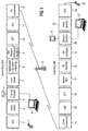
- reference numerals 105A, 105B denote respectively portable telephone device.
- Reference numerals 106A and 106B denote base stations of a wireless transmission system.
- the portable telephone device 105A uses a predetermined channel to be engaged in radio communication with the base station 106A in the cell 101A.
- the same channel is used in the adjacent cell 101B so that the portable telephone device 105B is engaged in radio communication with the base station 106B.
- QPSK modulation Quadrature Phase Shift Keying; Four Phase Transition Modulation
- modulated sending signal are defined as x (A) 2
- modulated sending signal are defined as x (A) 1 , x (A) 2 , x (A) 3 , ... ... x (A) k-1 , x (A) k , x (A) k+1 , ... ... and x (B) 1 , x (B) 2 , x (B) 3 , ... ... x (B) k-1 , x (B) k , x (B) k+1 , ... ...
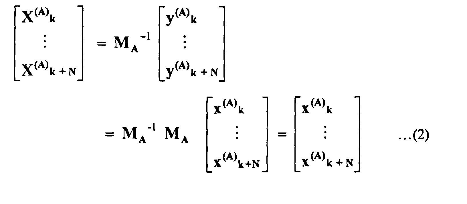
- the grouped sending signal series x (A) k , ... ... x (A) k+N and a predetermined Nth normal orthogonal matrix M A are multiplied in order as shown in the following equation.
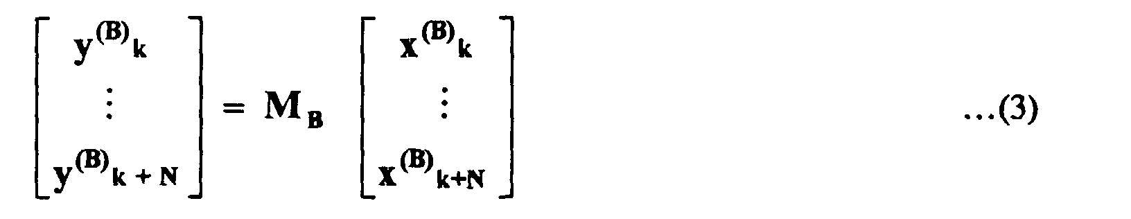
- the grouped sending signal series x (B) k , ... ...X (B) k+N and the predetermined Nth normal orthogonal matrix M B are multiplied in order for each group as shown in the following equation.
- the Nth normal orthogonal matrix M B which is used in the portable telephone device 5B and the Nth normal orthogonal matrix M A which is used in the portable telephone device 105A are matrixes which are completely different from each other.
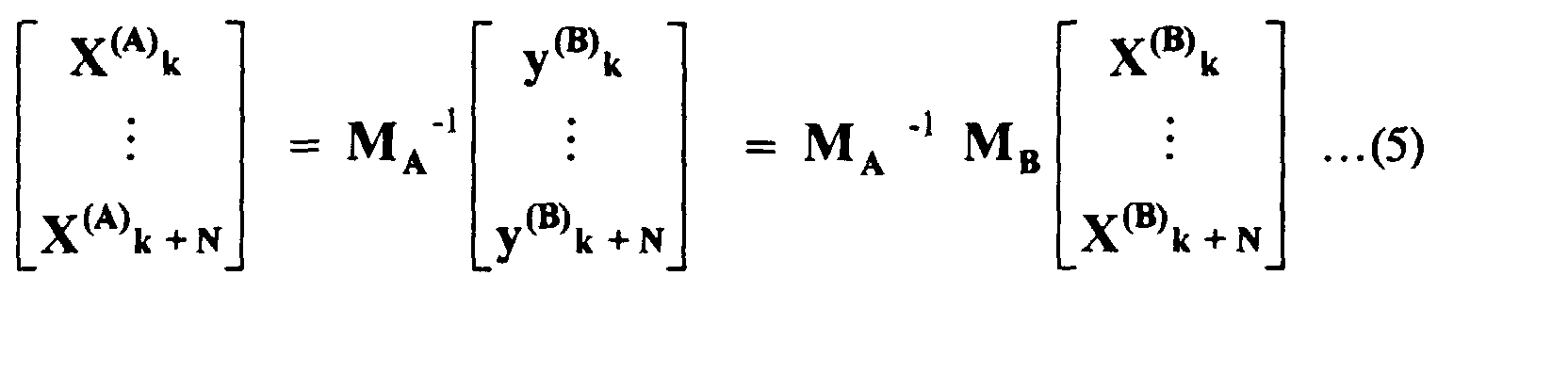
- the sending signal CA sent by the portable telephone device 105A reaches, but the sending signal CB sent by the portable telephone device 105B also reaches depending on the situation. In that case, the sending signal CB from the portable telephone device 105B acts as an interference wave I.
- the signal level of the sending signal CB is large as compared with the sending signal CA from the portable telephone device 105A, trouble is caused to communication with the portable telephone device 105A.
- the signal is a sending signal from either of the portable telephone devices 105A or 105B so that it is feared that the sending signal CB form the portable telephone device 105B is received by mistake.
- the orthogonal matrix which is different for each communication at the sending side is multiplied with the signal series.
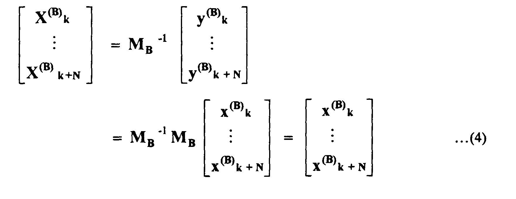
- the received signal series is multiplied with the inverse matrix of the orthogonal matrix which is used on the sending side (namely, the communication partner of its own station) so that the original signal series before the orthogonal conversion is restored.
- the leakage problem is avoided when the sending signal CB of the portable telephone device 105B is received by the base station 106A. For the same reason, the leakage problem can be also avoided even when the base station 106B receives the sending signal CA of the portable telephone device 105A.
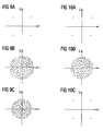
- the phase state is present at a position where the phase state becomes ⁇ /4, 3 ⁇ /4, 5 ⁇ /4 or 7 ⁇ /4.
- the base station 106A does not recognize that the signal series is either the sending signal from the communication partner or the interference wave, the demodulation processing is performed as in the normal receiving processing.
- the phase state is not brought back to the original state so that the phase state becomes a random state. Consequently, even when the signal series shown in Fig. 10C is QPSK demodulated, the sending data from the portable telephone device 105B is not restored..
- the randomizing according to ROT provides for an minimization of interference effects by the randomizing procedure, the interference is not canceled totally as this the case e.g. in TDMA. furthermore, as in OFDM systems usually no training sequence or midamble is used, the distinction between a wanted and an unwanted signal generally is difficult.
- a transmitter for the wireless transmission of information data comprises means for random orthogonal transforming (ROT) of blocks of data to be transmitted, by a multiplication of a vector comprising the data of one block with a matrix. Further more means for the transmission of data originating from the means for random orthogonal transforming are provided.
- the matrix operation uses a matrix comprising n orthogonal columns, n being the number of data samples comprised in one of said blocks. According to the present invention the number of rows of said matrix is larger than the number of said columns of said matrix. Note: Generally, when the input data are represented as a row vector, the ROT matrix has more columns than rows, and when the input data are represented as a column vector, the ROT matrix has more rows than columns. Therefore, according to the present invention an oblong matrix is provided (in contrast to the square matrix according to the prior art).
- the number of rows of said matrix can be equal to M*n, n being the number of columns of said matrix and M being an integer larger than 1.
- a modulator can be provided outputting said blocks of data being supplied to said means for random orthogonal transforming.
- the means for random orthogonal transforming can supply the transformed data to an inverse fast Fourier transform (IFFT) circuit.
- IFFT inverse fast Fourier transform
- the transmitter is a transmitter of the OFDM type.
- the means for random orthogonal transforming of blocks of data to be transmitted are provided with a plurality of mutually orthogonal matrices to provide for a frequency band division according to the OFDM system. Therefore according to this aspect, a multiple access technique for OFDM systems is provided still efficiently minimizing interference effects.
- the transmitter can comprise a convolution encoder, wherein the convolution encoder is implemented by reconstructing the matrix from a convolution code matrix.
- the elements of the matrix are coefficients of polynomials of a convolutional function of the convolution encoder.
- the coefficients of the polynomials can be shift in each column vector of the matrix implementing the convolution encoder.
- the transmitter can furthermore comprise means for inverse random orthogonal transforming of blocks of data received by multiplying a received data block by a transpose matrix of the matrix used for the data to be transmitted.
- the transmitter can comprise means for inverse random orthogonal transforming an convolutional decoding blocks of data received by applying a Trellis decoding technique.
- Said means for inverse random orthogonal transforming an convolutional decoding of blocks of data received can comprise means for calculating an equivalent vector of a received symbol, means for generating a Trellis state matrix on the basis of the elements of the equivalent vector, means for calculating path matrix and adding up the calculated path matrix with original state matrix, and means for deciding the decoded symbol by comparing the path matrix of the two paths leading respectively to a new state.
- a transmitting system comprising a plurality of base stations and a plurality of mobile stations.
- each mobile station and base station respectively, comprises a transmitter with the features as set forth above.
- Blocks of data to be transmitted are processed by a random orthogonal transformation by means of a multiplication of a vector comprising the data of one block with the matrix.
- the data originating from the step of random orthogonal transforming are then transmitted.
- the matrix operation uses a matrix comprising n orthogonal columns, n being the number of data samples comprised in one of set blocks, wherein the number of rows of said matrix is larger than the number of said columns of said matrix.
- a method for the generation of matrices to be used for the random orthogonal transformation of blocks of data in a wireless transmission chain is provided.
- a square matrix with orthogonal column vectors and orthogonal row vectors is provided.
- the square matrix is divided to great M matrices the number of rows of each of that matrices being equal to M*n, n being the number of columns of each of that matrices and M being an integer larger than one.
- M matrices is than allocated to a transmitter in a transmission chain.
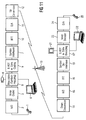
- Voice data for example from a hand set 1 are passed through A/D converter 2 and then supplied to a voice codec 3.
- the output of the voice codec 3 is supplied to a channel encoder 5.
- other data such as video data from a camera 4 or data from a laptop computer 6 can be input to the channel encoder 5.
- the channel encoded data are passed through a interleaver 7 and then given to a modulator 8 effecting the symbol mapping.
- the modulated data are the given to a random orthogonal transform (ROT) circuit 9 outputting transformed data to an inverse fast Fourier transformation (IFFT) circuitry 10.
- ROT random orthogonal transform
- IFFT inverse fast Fourier transformation
- the output data from the FFT 16 are the processed by a inverse ROT process 17.
- the output data from the inverse ROT circuitry 17 is passed through a bit mapping circuitry 18, a deinterleaver 19 and then supplied to a channel decoder 20.
- the channel decoder 20 optionally outputs decoded data to a monitor 21 (in case of video data), to a laptop computer 22 or to a voice decoder 23, a D/A converter 24 and the hand set 25 in case of voice data.
- the object of the present invention particularly lies in the procedures as they are effected by the ROT circuit 9 and the inverse ROT circuit 17.
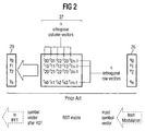
- FIG. 2 once again shows a ROT-matrix operation according to EP 98 104 287.2.
- An input symbol vector 26 comprising n data samples and emerging from the modulator 8, e. g. is multiplied with a ROT matrix 27 having n orthogonal column vectors and n orthogonal row vectors. With other words the input symbol vector 26 is multiplied with a square matrix 27. Therefore the ROT-operation generates a symbol vector 28 after the ROT-operation, wherein the transformed symbol vector 28 comprises again n data samples which were passed through a IFFT circuitry 10.
- ROT therefore is a technique which randomizes information data symbol vectors before the IFFT and the OFDM modulation by an orthogonal matrix.
- This randomization is untied after FFT, OFDM-demodulation in the receiving side.
- Interference signals are randomized by another matrix. Therefore some interference is left randomized after untying in the receiving side.
- the random orthogonal transform is just randomizing interference. As no training sequence or mid-amble is used is used in OFDM, it is difficult to distinguish a wanted signal from an interference signal.
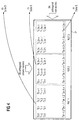
- Figure 3 shows the ROT matrix operation according to the present invention. After the modulation the symbols are divided into a size adapted for the IFFT. The symbols are then treated as a vector of a complex number which size is n. According to the present invention, the input symbol vector 26 is multiplied with a ROT matrix 29 having more rows than columns.
- the ROT matrix has more columns than rows
- the ROT matrix has more rows than columns
- the number of rows can be m times the number of columns. Therefore the number of symbols is increased by the ROT matrix operation.
- the number of symbols input to the ROT matrix operation therefore is 1/m of the size of the IFFT(n).
- n column vectors are still mutually orthogonal. However, as there are e.g. 3n row vectors and therefor more row vectors than column vectors, these row vectors are no longer mutually orthogonal. (There are only n orthogonal bases of n element vectors.)
- the symbol vector 28 after the ROT operation will contain more samples, e.g. 3n samples in case orthogonal column vectors and 3n row vectors generate the ROT matrix 29.
- the present invention is not limited to binary codes, the values of the vectors can also take higher values, as e.g. 0,1; 1,0;0,0 or 1,1.
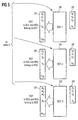
- Figure 4 and figure 5 show an example for the generation of the oblong matrices according to the present invention.
- square matrix 31 comprising 3N orthogonal column vectors and 3N orthogonal row vectors is created.
- Said square matrix 31 is then divided e.g. in three oblong matrices ROT1, ROT2, ROT3.
- the oblong matrices ROT1, ROT2, ROT3 (29, 29', 29'') therefore will still have orthogonal column vectors, however the row vectors can no longer be orthogonal.
- the m*n columns of the square matrix therefore are divided into m oblong matrices.
- the matrices ROT1, ROT2, ROT3 satisfy the equation as it is shown in figure 7.
- the m oblong matrices and then be respectively allocated to different base station/mobile station transmission systems.
- the matrix ROT1 can be allocated to a base station 1 and mobile stations belonging to the base station 1
- the matrix ROT2 (29') can be allocated to a transmission system comprising a base station 2 and mobile stations belonging to said base station 2
- the oblong matrix ROT3 (29'') can be allocated to a transmission system comprising a base station 3 and mobile stations belonging to said base station 3. (see figure 5).
- the randomization can be easily restored by multiplication with a transpose matrix ROT T .
- the wanted signal is restored by multiplying with a transpose matrix of ROT1.
- the receiver 30 keeps this matrix ROT1 t .
- Any interference signal which is randomized for example by ROT2 will be canceled by the multiplication procedure with a transpose matrix of ROT1, as ROT2 is orthogonal to ROT1.
- the components of the ROT matrices can also assume complex values.
- the channels are not ideal and synchronization between the cells is not complete.
- the interference is not canceled totally, but at least the interference is reduced more efficient than in the case of a randomization procedure as known from EP 98 104 287.2.
- a plurality of mutually orthogonal matrices is used in one base station.
- a plurality of mutually orthogonal matrices is allocated to the same base station.
- the frequency band of OFDM can the be divided by these orthogonal matrices. Therefore, according to this aspect of the present invention, a multiple access technique in OFDM is provided.
- interference symbols can be randomized by different orthogonal matrices, which individually randomize modulated symbols as shown above. Interference can be canceled by using non-square matrices, which randomize symbols orthogonally to each other. Oblong matrices increase the number of symbols after randomizing. According to the above-shown embodiments the increased symbols are only used to keep orthogonality with interference signals.
- the multiplication with a ROT matrix can also be used for convolutional coding/decoding.
- a Viterbi algorithm can be used solving the randomization. Therefore, according to this aspect of the present invention, convolutional coding and the ROT matrix technique using oblong matrices is combined. As it is shown in Figure 11 the original channel coding can therefore be replaced the ROT multiplication operation, which stills keeps orthogonality with the interference signals.
- the ROT multiplication unit 9' simultaneously effects the convolutional coding.
- the unit 17' for multiplicating the deinterleaved symbol with the transpose of the ROT matrix used in the unit 9' simultaneously effects a convolutional decoding operation, such as for example, a Viterbi decoding.
- a convolutional decoding operation such as for example, a Viterbi decoding.
- FIG. 12 shows a ROT multiplication unit modified according to the present aspect of the invention. Note:
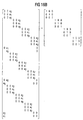
- Figure 13 once again shows a matrix 40 which is a matrix reconstructed from a convolution coding matrix.
- the matrix A (reference sign 40 in Figure 13) is then divided into three submatrices A 0 , A 1 , A 2 (see Figure 14) which three submatrices A 0 , A 1 , A 2 are combined together horizontally.
- the elements a 0 , a 1 , a 2 of the convolutional coding matrix A respectively represent terms of polynomials of a convolution function.
- the terms cannot only be binary values (e.g. -1, 1), but also real and complex values.
- the multiplication of the input symbol vector by the matrix A corresponds to the well-known convolution coding operation using a shift register as it is schematically represented in Figure 15. Instead of shifting input symbols, as it is the case according to the well-known convolution coding procedure, the terms (elements of the matrix A) representing polynomials of the convolution function are already shifted in each column vector (see Figure 15). Instead of taking a logical EXOR as it is the case in the known convolution coding, according to the present invention the products of respectively a term of the matrix and a symbol are summed along with the multiplication operation of the input symbol vector and the matrix A.
- All row vectors of the matrix 40 according to the present invention are orthogonal with each other so that the product of said matrix with a transposed matrix (complex conjugate transposed matrix) is a unit matrix as shown in Figure 16. All diagonal elements of the unit matrix as shown in Figure 16 are 1, whereas all other elements of said unit matrix are 0. Therefore the transposed matrix can be used in the unit 17' on the reception side to solve randomization and coding simultaneously.
- orthogonal polynomial terms other ROT matrices can be generated which are respectively orthogonal to the original ROT matrix (see Figure 17). Therefore interference which is coded by orthogonal ROT matrices can be canceled.
- the elements of the received ROT transformed symbol are summed up as shown in the second equation of Figure 18 to generate an equivalent vector of xA .
- the generated equivalent vector xA is composed of n elements s 0 , s 1 , ...s n-1 representing respectively a summation result.
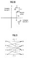
- a state matrix as shown in Figure 19 is generated. If the modulation scheme is QPSK the number of states 4 k-1 , wherein k is the constraint length.
- the path metrics (Hamming distances) of the state matrix using the symbols of equivalent vectors are calculated. Said calculated path metrics are summed up with original state metrics.
- the original Trellis state matrix is shown in Figure 21. Respectively the two accumulated metrics of paths leading to a new state (see Figure 19) are then compared. Finally the received decoded symbol is decided to be the path having the larger path matrix and therefore the higher reliability.
- a Viterbi decoding operation is effected using soft decision information, as the metric is calculated by measuring the distance between the received actual symbol and estimated places generated from each state transition (see Figure 20).
- the oblong ROT matrix can also be used for convolutional coding/decoding.
- a Viterbi algorithm can be used solving the randomization by a multiplication with a transpose matrix or a Trellis decoding technique. Therefore, according to this aspect of the present invention, convolutional coding and the ROT matrix technique using oblong matrices is combined. As it is shown in Figure 11 the original channel coding can therefore be replaced the ROT multiplication operation, which stills keeps orthogonality with the interference signals.
Abstract
Description

Note:
- the matrix A is still an oblong matrix,
- the input data are represented by a row (and not by a vector as it is the case in the preceding figures). Therefore the ROT matrix now has more columns than rows. Generally, when the input data are represented as a row vector, the ROT matrix has more columns than rows, and when the input data are represented as a column vector, the ROT matrix has more rows than columns.
Claims (24)
- Transmitter for the wireless transmission of information data, comprising:means (9) for random orthogonal transforming of blocks of data to be transmitted, by a multiplication of a vector (26) comprising the data of one block with a matrix (29), andmeans for the transmission of data originating from the means (9) for random orthogonal transforming, whereinfor the matrix operation a matrix (29) comprising n orthogonal columns is used, n being the number of data samples comprised in one of said blocks, andthe number of rows of said matrix (29) is larger than the number of said columns of said matrix (29), when the data of one block is represented as a column vector.
- Transmitter according to claim 1,
characterized in thatthe number of rows of said matrix (29) is equal to M*n, n being the number of columns of said matrix and M being an integer larger than one. - Transmitter according to anyone of claims 1 or 2,
characterized in thata modulator (8) is provided outputting said blocks of data being supplied to said means (9) for random orthogonal transforming. - Transmitter according to anyone of the preceding claims,
characterized in thatthe means (9) for random orthogonal transforming supplies the transformed data to an inverse fast Fourier transform circuit (10). - Transmitter according to anyone of the preceding claims,
characterized in thatthe transmitter is a transmitter of the OFDM type, andthe means (9) for random orthogonal transforming of blocks of data to be transmitted are provided with a plurality of mutually orthogonal matrices (29, 29', 29'') to provide for a frequency band division according to the OFDM system. - Transmitter according to anyone of the preceding claims,
characterized in thatit comprises a convolution encoder (9'), wherein the convolution encoder (9') is implemented by reconstructing the matrix (40) from a convolution code matrix. - Transmitter according to claim 6,
characterized in thatthe elements of the matrix (40) are coefficients of polynomials of a convolution function of the convolution encoder (9'). - Transmitter according to claim 7,
characterized in thatthe coefficients of the polynomials are shifted in each column vector of the matrix (40) implementing the convolution encoder (9'). - Transmitter according to anyone of the preceding claims,
characterized in thatit comprises means (17, 17') for inverse random orthogonal transforming of blocks of data received by multiplying a received data block by a transpose matrix of the matrix used for the data to be transmitted. - Transmitter according to anyone of claims 1 to 8,
characterized in thatit comprises means for inverse random orthogonal transforming and convolutional decoding blocks of data received by applying a Trellis decoding technique. - Transmitter according to claim 10,
characterized in thatsaid means for inverse random orthogonal transforming and convolutional decoding of blocks of data received comprisemeans for calculating an equivalent vector of a received symbol,means for generating a Trellis state matrix on the basis of elements ofmeans for calculating path metrics and adding up the calculated path metrics with original state metrics, andmeans for deciding the decoded symbol by comparing the path metrics of the two paths leading respectively to a new state. - Transmitting system,
comprising a plurality of base stations and a plurality of mobile stations,
wherein each mobile station and base station, respectively, comprises a transmitter according to anyone of the claims 1 to 12. - Method for the wireless transmission of information data,
comprising the following steps:random orthogonal transforming (9) blocks of data to be transmitted, by a multiplication of a vector (26) comprising the data of one block with a matrix (29), andtransmitting (13) data originating from the step of random orthogonal transforming (9), whereinfor the matrix operation a matrix (29) comprising n orthogonal columns is used, n being the number of data samples comprised in one of said blocks, andthe number of rows of said matrix (29) is larger than the number of said columns of said matrix (29). - Method according to claim 13,
characterized in thatthe number of rows of said matrix (29) is equal to M*n, n being the number of columns of said matrix (29) and M being an integer larger than one. - Method according to anyone of claims 13 or 14,
characterized bythe step of modulating (8) data to output said blocks of data being supplied to the step of random orthogonal transforming (9). - Method according to anyone of claims 14 or 15,
characterized bythe step of inverse fast Fourier transforming (10) the data emerging from the step of random orthogonal transforming (9). - Method according to anyone of claims 13 to 16,
characterized in thatwhen receiving the transmitted data, the received data are processed (17, 17') by inverse random orthogonal transforming blocks of said received data by multiplying a received data block by a transpose matrix of the matrix used for the data to be transmitted. - Method for convolutional encoding of a digital data blocks,
comprising the steps according to anyone of the methods according to claims 14 to 18,
wherein the matrix of the matrix operation step is reconstructed from a convolution code matrix (40) such that the matrix operation step provides both for a random orthogonal transformation and a convolutional encoding. - Method according to claim 18,
characterized in thatthe elements of the matrix (40) are coefficients of polynomials of a convolution function. - Method according to claim 19,
characterized in thatthe coefficients of the polynomials are shifted in each column vector of the matrix (40) of the matrix operation step. - Method for decoding digital data blocks encoded according to a method of anyone of claims 18 to 20,
characterized in thatit comprises step of inverse random orthogonal transforming and convolutional decoding blocks of data received by a Trellis decoding technique. - Method according to claim 21,
characterized in thatsaid step of inverse random orthogonal transforming and convolutional decoding of blocks of data received comprises:calculating an equivalent vector of a received symbol,generating a Trellis state matrix,calculating path metrics and adding up the calculated path metrics with original state metrics, anddeciding the decoded symbol by comparing the path metrics of the two paths leading respectively to a new state of the Trellis state matrix. - Method for generating matrices to be used for the random orthogonal transformation (9) of blocks of data in a transmission chain,
comprising the following steps:providing a square matrix (31) with orthogonal column vectors and orthogonal row vectors,dividing the square matrix (31) to create M matrices (29, 29', 29''), the number of rows of each of said matrices (29, 29', 29'') being equal to M*n, n being the number of columns of each of said matrices (29, 29', 29'') and M being an integer larger than one, andallocating each of said M matrices (29, 29', 29'') to a transmitter in a transmission chain. - Method for generating matrices to be used for the random orthogonal transformation (9) of blocks of data in a transmission chain,
comprising the following steps:providing a square matrix (31) with orthogonal column vectors and orthogonal row vectors,dividing the square matrix (31) to create M matrices (29, 29', 29''), the number of rows of each of said matrices (29, 29', 29'') being equal to M*n, n being the number of columns of each of said matrices (29, 29', 29'') and M being an integer larger than one, andallocating respectively a plurality of said M matrices (29, 29', 29'') to one base station of a wireless transmission system.
Priority Applications (4)
| Application Number | Priority Date | Filing Date | Title |
|---|---|---|---|
| EP98122469A EP0966133B1 (en) | 1998-06-15 | 1998-11-26 | Orthogonal transformations for interference reduction in multicarrier systems |
| US09/330,328 US6549581B1 (en) | 1998-06-15 | 1999-06-11 | Transmitter and method to cancel interference in OFDM communication |
| JP16891899A JP4351762B2 (en) | 1998-06-15 | 1999-06-15 | Wireless information transmission apparatus and wireless information transmission method |
| US10/037,137 US6631168B2 (en) | 1998-06-15 | 2002-01-04 | Generating matrices to be used for the random orthogonal transformation of blocks of data in a transmission chain |
Applications Claiming Priority (3)
| Application Number | Priority Date | Filing Date | Title |
|---|---|---|---|
| EP98110931 | 1998-06-15 | ||
| EP98110931 | 1998-06-15 | ||
| EP98122469A EP0966133B1 (en) | 1998-06-15 | 1998-11-26 | Orthogonal transformations for interference reduction in multicarrier systems |
Publications (3)
| Publication Number | Publication Date |
|---|---|
| EP0966133A2 true EP0966133A2 (en) | 1999-12-22 |
| EP0966133A3 EP0966133A3 (en) | 2002-07-24 |
| EP0966133B1 EP0966133B1 (en) | 2005-03-02 |
Family
ID=26149348
Family Applications (1)
| Application Number | Title | Priority Date | Filing Date |
|---|---|---|---|
| EP98122469A Expired - Lifetime EP0966133B1 (en) | 1998-06-15 | 1998-11-26 | Orthogonal transformations for interference reduction in multicarrier systems |
Country Status (3)
| Country | Link |
|---|---|
| US (2) | US6549581B1 (en) |
| EP (1) | EP0966133B1 (en) |
| JP (1) | JP4351762B2 (en) |
Cited By (5)
| Publication number | Priority date | Publication date | Assignee | Title |
|---|---|---|---|---|
| WO2003026193A1 (en) * | 2001-09-18 | 2003-03-27 | Siemens Aktiengesellschaft | Method and communication system device for the generation or processing of ofdm symbols in a transmission system with spread user data |
| EP1317809A1 (en) * | 2000-08-09 | 2003-06-11 | Avway.Com Inc. | Method and system for steganographically embedding information bits in source signals |
| US7298785B2 (en) | 2001-07-04 | 2007-11-20 | Kabushiki Kaisha Toyota Chuo Kenkyusho | Multicarrier demodulation method and apparatus, and multicarrier modulation method and apparatus |
| CN101710828B (en) * | 2009-08-24 | 2013-07-24 | 清华大学 | Orthogonal random phase coding technology and application thereof in volume hologram memories |
| US9755876B2 (en) | 1999-11-09 | 2017-09-05 | Tq Delta, Llc | System and method for scrambling the phase of the carriers in a multicarrier communications system |
Families Citing this family (148)
| Publication number | Priority date | Publication date | Assignee | Title |
|---|---|---|---|---|
| US7430257B1 (en) * | 1998-02-12 | 2008-09-30 | Lot 41 Acquisition Foundation, Llc | Multicarrier sub-layer for direct sequence channel and multiple-access coding |
| US5955992A (en) * | 1998-02-12 | 1999-09-21 | Shattil; Steve J. | Frequency-shifted feedback cavity used as a phased array antenna controller and carrier interference multiple access spread-spectrum transmitter |
| US7215772B2 (en) * | 1999-11-09 | 2007-05-08 | Chaoticom, Inc. | Method and apparatus for remote digital key generation |
| EP1236326A1 (en) * | 1999-11-27 | 2002-09-04 | Deutsche Telekom AG | Method for co-channel interference cancelation in a multicarrier communication system |
| US7477703B2 (en) * | 2000-02-22 | 2009-01-13 | Nokia Mobile Phones, Limited | Method and radio system for digital signal transmission using complex space-time codes |
| US6865237B1 (en) * | 2000-02-22 | 2005-03-08 | Nokia Mobile Phones Limited | Method and system for digital signal transmission |
| FI112565B (en) * | 2000-02-22 | 2003-12-15 | Nokia Corp | Method and radio system for transmitting a digital signal |
| US6687307B1 (en) * | 2000-02-24 | 2004-02-03 | Cisco Technology, Inc | Low memory and low latency cyclic prefix addition |
| US8363744B2 (en) | 2001-06-10 | 2013-01-29 | Aloft Media, Llc | Method and system for robust, secure, and high-efficiency voice and packet transmission over ad-hoc, mesh, and MIMO communication networks |
| US7006579B2 (en) * | 2000-09-29 | 2006-02-28 | Nokia Corporation | ISI-robust slot formats for non-orthogonal-based space-time block codes |
| FI20002845A (en) * | 2000-12-22 | 2002-06-23 | Nokia Corp | Digital signal transmission |
| US8670390B2 (en) | 2000-11-22 | 2014-03-11 | Genghiscomm Holdings, LLC | Cooperative beam-forming in wireless networks |
| US7095731B2 (en) * | 2000-12-13 | 2006-08-22 | Interdigital Technology Corporation | Modified block space time transmit diversity encoder |
| US10425135B2 (en) | 2001-04-26 | 2019-09-24 | Genghiscomm Holdings, LLC | Coordinated multipoint systems |
| US10931338B2 (en) | 2001-04-26 | 2021-02-23 | Genghiscomm Holdings, LLC | Coordinated multipoint systems |
| US10355720B2 (en) | 2001-04-26 | 2019-07-16 | Genghiscomm Holdings, LLC | Distributed software-defined radio |
| US9893774B2 (en) | 2001-04-26 | 2018-02-13 | Genghiscomm Holdings, LLC | Cloud radio access network |
| US9819449B2 (en) | 2002-05-14 | 2017-11-14 | Genghiscomm Holdings, LLC | Cooperative subspace demultiplexing in content delivery networks |
| US7269224B2 (en) * | 2001-09-17 | 2007-09-11 | Bae Systems Information And Electronic Systems Integration Inc. | Apparatus and methods for providing efficient space-time structures for preambles, pilots and data for multi-input, multi-output communications systems |
| US10644916B1 (en) | 2002-05-14 | 2020-05-05 | Genghiscomm Holdings, LLC | Spreading and precoding in OFDM |
| US10142082B1 (en) | 2002-05-14 | 2018-11-27 | Genghiscomm Holdings, LLC | Pre-coding in OFDM |
| US10200227B2 (en) | 2002-05-14 | 2019-02-05 | Genghiscomm Holdings, LLC | Pre-coding in multi-user MIMO |
| US9628231B2 (en) | 2002-05-14 | 2017-04-18 | Genghiscomm Holdings, LLC | Spreading and precoding in OFDM |
| US7889819B2 (en) * | 2002-10-04 | 2011-02-15 | Apurva Mody | Methods and systems for sampling frequency offset detection, correction and control for MIMO OFDM systems |
| TWI237955B (en) * | 2003-11-24 | 2005-08-11 | Ind Tech Res Inst | Apparatus of transmitter and receiver for MIMO MC-CDMA system |
| US7483932B1 (en) * | 2004-05-05 | 2009-01-27 | Sun Microsystems, Inc. | Method and system for computing multidimensional fast Fourier transforms |
| US11184037B1 (en) | 2004-08-02 | 2021-11-23 | Genghiscomm Holdings, LLC | Demodulating and decoding carrier interferometry signals |
| US11552737B1 (en) | 2004-08-02 | 2023-01-10 | Genghiscomm Holdings, LLC | Cooperative MIMO |
| US11431386B1 (en) | 2004-08-02 | 2022-08-30 | Genghiscomm Holdings, LLC | Transmit pre-coding |
| KR100757078B1 (en) * | 2006-01-03 | 2007-09-10 | 주식회사 휴커넥스 | OFDM transmitter, system and encoding method for removing ICI |
| JP4340732B2 (en) * | 2006-08-03 | 2009-10-07 | 日本電気株式会社 | Information management method, recording method and information recording / reproducing apparatus for information recording medium |
| CN101574010B (en) * | 2007-01-05 | 2010-12-08 | 华为技术有限公司 | Two-dimensional reference signal sequences |
| US8073393B2 (en) * | 2009-02-05 | 2011-12-06 | Qualcomm Incorporated | Methods and systems for least squares block channel estimation |
| US9288089B2 (en) | 2010-04-30 | 2016-03-15 | Ecole Polytechnique Federale De Lausanne (Epfl) | Orthogonal differential vector signaling |
| US9077386B1 (en) | 2010-05-20 | 2015-07-07 | Kandou Labs, S.A. | Methods and systems for selection of unions of vector signaling codes for power and pin efficient chip-to-chip communication |
| US9251873B1 (en) | 2010-05-20 | 2016-02-02 | Kandou Labs, S.A. | Methods and systems for pin-efficient memory controller interface using vector signaling codes for chip-to-chip communications |
| US9985634B2 (en) | 2010-05-20 | 2018-05-29 | Kandou Labs, S.A. | Data-driven voltage regulator |
| US9288082B1 (en) | 2010-05-20 | 2016-03-15 | Kandou Labs, S.A. | Circuits for efficient detection of vector signaling codes for chip-to-chip communication using sums of differences |
| US10667148B1 (en) | 2010-05-28 | 2020-05-26 | Cohere Technologies, Inc. | Methods of operating and implementing wireless communications systems |
| US8976851B2 (en) | 2011-05-26 | 2015-03-10 | Cohere Technologies, Inc. | Modulation and equalization in an orthonormal time-frequency shifting communications system |
| US9130638B2 (en) | 2011-05-26 | 2015-09-08 | Cohere Technologies, Inc. | Modulation and equalization in an orthonormal time-frequency shifting communications system |
| US10681568B1 (en) | 2010-05-28 | 2020-06-09 | Cohere Technologies, Inc. | Methods of data channel characterization and uses thereof |
| US11943089B2 (en) | 2010-05-28 | 2024-03-26 | Cohere Technologies, Inc. | Modulation and equalization in an orthonormal time-shifting communications system |
| US9444514B2 (en) | 2010-05-28 | 2016-09-13 | Cohere Technologies, Inc. | OTFS methods of data channel characterization and uses thereof |
| US9071286B2 (en) | 2011-05-26 | 2015-06-30 | Cohere Technologies, Inc. | Modulation and equalization in an orthonormal time-frequency shifting communications system |
| US8547988B2 (en) | 2010-05-28 | 2013-10-01 | Ronny Hadani | Communications method employing orthonormal time-frequency shifting and spectral shaping |
| US9071285B2 (en) | 2011-05-26 | 2015-06-30 | Cohere Technologies, Inc. | Modulation and equalization in an orthonormal time-frequency shifting communications system |
| US9031141B2 (en) | 2011-05-26 | 2015-05-12 | Cohere Technologies, Inc. | Modulation and equalization in an orthonormal time-frequency shifting communications system |
| US9590779B2 (en) | 2011-05-26 | 2017-03-07 | Cohere Technologies, Inc. | Modulation and equalization in an orthonormal time-frequency shifting communications system |
| US9294315B2 (en) | 2011-05-26 | 2016-03-22 | Cohere Technologies, Inc. | Modulation and equalization in an orthonormal time-frequency shifting communications system |
| WO2013148546A1 (en) * | 2012-03-26 | 2013-10-03 | Shlomo Selim Rakib | Signal modulation method resistant to echo reflections and frequency offsets |
| US10003487B2 (en) | 2013-03-15 | 2018-06-19 | Cohere Technologies, Inc. | Symplectic orthogonal time frequency space modulation system |
| US9929783B2 (en) | 2012-06-25 | 2018-03-27 | Cohere Technologies, Inc. | Orthogonal time frequency space modulation system |
| US10469215B2 (en) | 2012-06-25 | 2019-11-05 | Cohere Technologies, Inc. | Orthogonal time frequency space modulation system for the Internet of Things |
| US9967758B2 (en) | 2012-06-25 | 2018-05-08 | Cohere Technologies, Inc. | Multiple access in an orthogonal time frequency space communication system |
| US9912507B2 (en) | 2012-06-25 | 2018-03-06 | Cohere Technologies, Inc. | Orthogonal time frequency space communication system compatible with OFDM |
| US10411843B2 (en) | 2012-06-25 | 2019-09-10 | Cohere Technologies, Inc. | Orthogonal time frequency space communication system compatible with OFDM |
| US10090972B2 (en) | 2012-06-25 | 2018-10-02 | Cohere Technologies, Inc. | System and method for two-dimensional equalization in an orthogonal time frequency space communication system |
| WO2014172377A1 (en) | 2013-04-16 | 2014-10-23 | Kandou Labs, S.A. | Methods and systems for high bandwidth communications interface |
| WO2014210074A1 (en) | 2013-06-25 | 2014-12-31 | Kandou Labs SA | Vector signaling with reduced receiver complexity |
| US9806761B1 (en) | 2014-01-31 | 2017-10-31 | Kandou Labs, S.A. | Methods and systems for reduction of nearest-neighbor crosstalk |
| EP3100424B1 (en) | 2014-02-02 | 2023-06-07 | Kandou Labs S.A. | Method and apparatus for low power chip-to-chip communications with constrained isi ratio |
| WO2015131203A1 (en) | 2014-02-28 | 2015-09-03 | Kandou Lab, S.A. | Clock-embedded vector signaling codes |
| US9509437B2 (en) | 2014-05-13 | 2016-11-29 | Kandou Labs, S.A. | Vector signaling code with improved noise margin |
| US11240076B2 (en) | 2014-05-13 | 2022-02-01 | Kandou Labs, S.A. | Vector signaling code with improved noise margin |
| US9112550B1 (en) | 2014-06-25 | 2015-08-18 | Kandou Labs, SA | Multilevel driver for high speed chip-to-chip communications |
| CN106797352B (en) | 2014-07-10 | 2020-04-07 | 康杜实验室公司 | High signal-to-noise characteristic vector signaling code |
| US9432082B2 (en) | 2014-07-17 | 2016-08-30 | Kandou Labs, S.A. | Bus reversable orthogonal differential vector signaling codes |
| KR102243423B1 (en) | 2014-07-21 | 2021-04-22 | 칸도우 랩스 에스에이 | Multidrop data transfer |
| CN106576087B (en) | 2014-08-01 | 2019-04-12 | 康杜实验室公司 | Orthogonal differential vector signaling code with embedded clock |
| US9674014B2 (en) | 2014-10-22 | 2017-06-06 | Kandou Labs, S.A. | Method and apparatus for high speed chip-to-chip communications |
| US10090973B2 (en) | 2015-05-11 | 2018-10-02 | Cohere Technologies, Inc. | Multiple access in an orthogonal time frequency space communication system |
| CN107925434B (en) | 2015-05-11 | 2021-02-05 | 凝聚技术公司 | System and method for simorthogonal time-frequency shift modulation and transmission of data |
| US10574317B2 (en) | 2015-06-18 | 2020-02-25 | Cohere Technologies, Inc. | System and method for providing wireless communication services using configurable broadband infrastructure shared among multiple network operators |
| US9866363B2 (en) | 2015-06-18 | 2018-01-09 | Cohere Technologies, Inc. | System and method for coordinated management of network access points |
| CN113193938B (en) | 2015-06-26 | 2023-10-27 | 康杜实验室公司 | High-speed communication system |
| EP4164152A1 (en) | 2015-06-27 | 2023-04-12 | Cohere Technologies, Inc. | Orthogonal time frequency space communication system compatible with ofdm |
| US10892547B2 (en) | 2015-07-07 | 2021-01-12 | Cohere Technologies, Inc. | Inconspicuous multi-directional antenna system configured for multiple polarization modes |
| US10693581B2 (en) | 2015-07-12 | 2020-06-23 | Cohere Technologies, Inc. | Orthogonal time frequency space modulation over a plurality of narrow band subcarriers |
| EP4138318A1 (en) | 2015-09-07 | 2023-02-22 | Cohere Technologies, Inc. | Multiple access using orthogonal time frequency space modulation |
| US11038733B2 (en) | 2015-11-18 | 2021-06-15 | Cohere Technologies, Inc. | Orthogonal time frequency space modulation techniques |
| US10055372B2 (en) | 2015-11-25 | 2018-08-21 | Kandou Labs, S.A. | Orthogonal differential vector signaling codes with embedded clock |
| EP3387748B1 (en) | 2015-12-09 | 2022-03-09 | Cohere Technologies, Inc. | Pilot packing using complex orthogonal functions |
| EP3408935B1 (en) | 2016-01-25 | 2023-09-27 | Kandou Labs S.A. | Voltage sampler driver with enhanced high-frequency gain |
| WO2017147439A1 (en) | 2016-02-25 | 2017-08-31 | Cohere Technologies | Reference signal packing for wireless communications |
| US10693692B2 (en) | 2016-03-23 | 2020-06-23 | Cohere Technologies, Inc. | Receiver-side processing of orthogonal time frequency space modulated signals |
| US9667307B1 (en) | 2016-03-31 | 2017-05-30 | Cohere Technologies | Wireless telecommunications system for high-mobility applications |
| EP4262162A3 (en) | 2016-03-31 | 2024-01-10 | Cohere Technologies, Inc. | Channel acquisition using orthogonal time frequency space modulated pilot signal |
| KR102276187B1 (en) | 2016-04-01 | 2021-07-12 | 코히어 테크놀로지스, 아이엔씨. | Iterative two-dimensional equalization of orthogonal time-frequency spatial modulated signals |
| KR102250054B1 (en) | 2016-04-01 | 2021-05-07 | 코히어 테크널러지스, 아이엔씨. | TOMLINSON-HARASHIMA precoding in OTFS communication system |
| US10242749B2 (en) | 2016-04-22 | 2019-03-26 | Kandou Labs, S.A. | Calibration apparatus and method for sampler with adjustable high frequency gain |
| US10003454B2 (en) | 2016-04-22 | 2018-06-19 | Kandou Labs, S.A. | Sampler with low input kickback |
| US10057049B2 (en) | 2016-04-22 | 2018-08-21 | Kandou Labs, S.A. | High performance phase locked loop |
| US10153591B2 (en) | 2016-04-28 | 2018-12-11 | Kandou Labs, S.A. | Skew-resistant multi-wire channel |
| WO2017190102A1 (en) | 2016-04-28 | 2017-11-02 | Kandou Labs, S.A. | Low power multilevel driver |
| US10333741B2 (en) | 2016-04-28 | 2019-06-25 | Kandou Labs, S.A. | Vector signaling codes for densely-routed wire groups |
| US10193716B2 (en) | 2016-04-28 | 2019-01-29 | Kandou Labs, S.A. | Clock data recovery with decision feedback equalization |
| US10938602B2 (en) | 2016-05-20 | 2021-03-02 | Cohere Technologies, Inc. | Iterative channel estimation and equalization with superimposed reference signals |
| WO2018031952A1 (en) | 2016-08-12 | 2018-02-15 | Cohere Technologies | Iterative multi-level equalization and decoding |
| US10826728B2 (en) | 2016-08-12 | 2020-11-03 | Cohere Technologies, Inc. | Localized equalization for channels with intercarrier interference |
| CN109804561B (en) | 2016-08-12 | 2023-07-21 | 凝聚技术公司 | Multiuser multiplexing of orthogonal time-frequency space signals |
| US9906358B1 (en) | 2016-08-31 | 2018-02-27 | Kandou Labs, S.A. | Lock detector for phase lock loop |
| US10411922B2 (en) | 2016-09-16 | 2019-09-10 | Kandou Labs, S.A. | Data-driven phase detector element for phase locked loops |
| WO2018064587A1 (en) | 2016-09-29 | 2018-04-05 | Cohere Technologies | Transport block segmentation for multi-level codes |
| US10965348B2 (en) | 2016-09-30 | 2021-03-30 | Cohere Technologies, Inc. | Uplink user resource allocation for orthogonal time frequency space modulation |
| US10200188B2 (en) | 2016-10-21 | 2019-02-05 | Kandou Labs, S.A. | Quadrature and duty cycle error correction in matrix phase lock loop |
| US10200218B2 (en) | 2016-10-24 | 2019-02-05 | Kandou Labs, S.A. | Multi-stage sampler with increased gain |
| US10372665B2 (en) | 2016-10-24 | 2019-08-06 | Kandou Labs, S.A. | Multiphase data receiver with distributed DFE |
| WO2018106731A1 (en) | 2016-12-05 | 2018-06-14 | Cohere Technologies | Fixed wireless access using orthogonal time frequency space modulation |
| WO2018129554A1 (en) | 2017-01-09 | 2018-07-12 | Cohere Technologies | Pilot scrambling for channel estimation |
| WO2018140837A1 (en) | 2017-01-27 | 2018-08-02 | Cohere Technologies | Variable beamwidth multiband antenna |
| US10568143B2 (en) | 2017-03-28 | 2020-02-18 | Cohere Technologies, Inc. | Windowed sequence for random access method and apparatus |
| EP3610582A4 (en) | 2017-04-11 | 2021-01-06 | Cohere Technologies, Inc. | Digital communication using dispersed orthogonal time frequency space modulated signals |
| EP3610576B1 (en) | 2017-04-14 | 2022-12-28 | Kandou Labs, S.A. | Pipelined forward error correction for vector signaling code channel |
| EP4109983A1 (en) | 2017-04-21 | 2022-12-28 | Cohere Technologies, Inc. | Communication techniques using quasi-static properties of wireless channels |
| WO2018200567A1 (en) | 2017-04-24 | 2018-11-01 | Cohere Technologies | Multibeam antenna designs and operation |
| US11063804B2 (en) | 2017-04-24 | 2021-07-13 | Cohere Technologies, Inc. | Digital communication using lattice division multiplexing |
| CN115333530A (en) | 2017-05-22 | 2022-11-11 | 康杜实验室公司 | Multi-mode data-driven clock recovery method and apparatus |
| US10243773B1 (en) | 2017-06-30 | 2019-03-26 | Genghiscomm Holdings, LLC | Efficient peak-to-average-power reduction for OFDM and MIMO-OFDM |
| US10637705B1 (en) | 2017-05-25 | 2020-04-28 | Genghiscomm Holdings, LLC | Peak-to-average-power reduction for OFDM multiple access |
| US10116468B1 (en) | 2017-06-28 | 2018-10-30 | Kandou Labs, S.A. | Low power chip-to-chip bidirectional communications |
| US10686583B2 (en) | 2017-07-04 | 2020-06-16 | Kandou Labs, S.A. | Method for measuring and correcting multi-wire skew |
| US10693587B2 (en) | 2017-07-10 | 2020-06-23 | Kandou Labs, S.A. | Multi-wire permuted forward error correction |
| EP3652907A4 (en) | 2017-07-12 | 2021-04-07 | Cohere Technologies, Inc. | Data modulation schemes based on the zak transform |
| US10203226B1 (en) | 2017-08-11 | 2019-02-12 | Kandou Labs, S.A. | Phase interpolation circuit |
| WO2019032605A1 (en) | 2017-08-11 | 2019-02-14 | Cohere Technologies | Ray tracing technique for wireless channel measurements |
| WO2019036492A1 (en) | 2017-08-14 | 2019-02-21 | Cohere Technologies | Transmission resource allocation by splitting physical resource blocks |
| US11102034B2 (en) | 2017-09-06 | 2021-08-24 | Cohere Technologies, Inc. | Lattice reduction in orthogonal time frequency space modulation |
| US11283561B2 (en) | 2017-09-11 | 2022-03-22 | Cohere Technologies, Inc. | Wireless local area networks using orthogonal time frequency space modulation |
| US11190308B2 (en) | 2017-09-15 | 2021-11-30 | Cohere Technologies, Inc. | Achieving synchronization in an orthogonal time frequency space signal receiver |
| US11532891B2 (en) | 2017-09-20 | 2022-12-20 | Cohere Technologies, Inc. | Low cost electromagnetic feed network |
| US11152957B2 (en) | 2017-09-29 | 2021-10-19 | Cohere Technologies, Inc. | Forward error correction using non-binary low density parity check codes |
| CN111919394B (en) | 2017-11-01 | 2022-05-27 | 凝聚技术公司 | Precoding in wireless systems using orthogonal time-frequency space-division multiplexing |
| WO2019113046A1 (en) | 2017-12-04 | 2019-06-13 | Cohere Technologies, Inc. | Implementation of orthogonal time frequency space modulation for wireless communications |
| US10467177B2 (en) | 2017-12-08 | 2019-11-05 | Kandou Labs, S.A. | High speed memory interface |
| US10326623B1 (en) | 2017-12-08 | 2019-06-18 | Kandou Labs, S.A. | Methods and systems for providing multi-stage distributed decision feedback equalization |
| CN116614337A (en) | 2017-12-28 | 2023-08-18 | 康杜实验室公司 | Method and apparatus for synchronously switching multiple-input demodulation comparators |
| US10554380B2 (en) | 2018-01-26 | 2020-02-04 | Kandou Labs, S.A. | Dynamically weighted exclusive or gate having weighted output segments for phase detection and phase interpolation |
| US11632270B2 (en) | 2018-02-08 | 2023-04-18 | Cohere Technologies, Inc. | Aspects of channel estimation for orthogonal time frequency space modulation for wireless communications |
| WO2019173775A1 (en) | 2018-03-08 | 2019-09-12 | Cohere Technologies, Inc. | Scheduling multi-user mimo transmissions in fixed wireless access systems |
| US11329848B2 (en) | 2018-06-13 | 2022-05-10 | Cohere Technologies, Inc. | Reciprocal calibration for channel estimation based on second-order statistics |
| US11522600B1 (en) | 2018-08-01 | 2022-12-06 | Cohere Technologies, Inc. | Airborne RF-head system |
| US10896043B2 (en) | 2018-09-28 | 2021-01-19 | Intel Corporation | Systems for performing instructions for fast element unpacking into 2-dimensional registers |
| US11343823B2 (en) | 2020-08-16 | 2022-05-24 | Tybalt, Llc | Orthogonal multiple access and non-orthogonal multiple access |
| CN113454964A (en) | 2019-01-25 | 2021-09-28 | 珍吉斯科姆控股有限责任公司 | Orthogonal and non-orthogonal multiple access |
| US11917604B2 (en) | 2019-01-25 | 2024-02-27 | Tybalt, Llc | Orthogonal multiple access and non-orthogonal multiple access |
| WO2020242898A1 (en) | 2019-05-26 | 2020-12-03 | Genghiscomm Holdings, LLC | Non-orthogonal multiple access |
| US11831472B1 (en) | 2022-08-30 | 2023-11-28 | Kandou Labs SA | Pre-scaler for orthogonal differential vector signalling |
Citations (3)
| Publication number | Priority date | Publication date | Assignee | Title |
|---|---|---|---|---|
| US5367516A (en) * | 1993-03-17 | 1994-11-22 | Miller William J | Method and apparatus for signal transmission and reception |
| EP0810738A2 (en) * | 1996-05-27 | 1997-12-03 | Sony Corporation | Receiving method and receiving apparatus |
| EP0865181A2 (en) * | 1997-03-10 | 1998-09-16 | Sony Corporation | Method of reducing cochannel interference |
Family Cites Families (2)
| Publication number | Priority date | Publication date | Assignee | Title |
|---|---|---|---|---|
| US4633256A (en) * | 1984-12-10 | 1986-12-30 | The United States Of America As Represented By The Secretary Of Commerce | Method and apparatus for four-beam radar |
| KR100573500B1 (en) * | 1996-02-27 | 2006-09-20 | 코닌클리케 필립스 일렉트로닉스 엔.브이. | Signal Coding and Decoding Method and Apparatus |
-
1998
- 1998-11-26 EP EP98122469A patent/EP0966133B1/en not_active Expired - Lifetime
-
1999
- 1999-06-11 US US09/330,328 patent/US6549581B1/en not_active Expired - Lifetime
- 1999-06-15 JP JP16891899A patent/JP4351762B2/en not_active Expired - Lifetime
-
2002
- 2002-01-04 US US10/037,137 patent/US6631168B2/en not_active Expired - Lifetime
Patent Citations (3)
| Publication number | Priority date | Publication date | Assignee | Title |
|---|---|---|---|---|
| US5367516A (en) * | 1993-03-17 | 1994-11-22 | Miller William J | Method and apparatus for signal transmission and reception |
| EP0810738A2 (en) * | 1996-05-27 | 1997-12-03 | Sony Corporation | Receiving method and receiving apparatus |
| EP0865181A2 (en) * | 1997-03-10 | 1998-09-16 | Sony Corporation | Method of reducing cochannel interference |
Non-Patent Citations (2)
| Title |
|---|
| JALALI A ET AL: "Performance comparison of direct spread and multicarrier CDMA systems" VEHICULAR TECHNOLOGY CONFERENCE, 1998. VTC 98. 48TH IEEE OTTAWA, ONT., CANADA 18-21 MAY 1998, NEW YORK, NY, USA,IEEE, US, 18 May 1998 (1998-05-18), pages 2042-2046, XP010288173 ISBN: 0-7803-4320-4 * |
| JUNG P.; BERENS F.; PLECHINGER J.: 'A generalized view on multicarrier CDMA mobile radio systems with Joint detection (Part 1)' FREQUENZ vol. 51, no. 7, 01 July 1997, BERLIN, DE, pages 174 - 185 * |
Cited By (12)
| Publication number | Priority date | Publication date | Assignee | Title |
|---|---|---|---|---|
| US9755876B2 (en) | 1999-11-09 | 2017-09-05 | Tq Delta, Llc | System and method for scrambling the phase of the carriers in a multicarrier communications system |
| US10187240B2 (en) | 1999-11-09 | 2019-01-22 | Tq Delta, Llc | System and method for scrambling the phase of the carriers in a multicarrier communications system |
| EP1317809A1 (en) * | 2000-08-09 | 2003-06-11 | Avway.Com Inc. | Method and system for steganographically embedding information bits in source signals |
| EP1317809A4 (en) * | 2000-08-09 | 2005-05-18 | Avway Com Inc | Method and system for steganographically embedding information bits in source signals |
| US7298785B2 (en) | 2001-07-04 | 2007-11-20 | Kabushiki Kaisha Toyota Chuo Kenkyusho | Multicarrier demodulation method and apparatus, and multicarrier modulation method and apparatus |
| WO2003026193A1 (en) * | 2001-09-18 | 2003-03-27 | Siemens Aktiengesellschaft | Method and communication system device for the generation or processing of ofdm symbols in a transmission system with spread user data |
| US7738571B2 (en) | 2001-09-18 | 2010-06-15 | Siemens Aktiengesellschaft | Method and communication system device for the generation or processing of OFDM symbols in a transmission system with spread user data |
| US8054902B2 (en) | 2001-09-18 | 2011-11-08 | Siemens Aktiengesellschaft | Method and communication system device for the generation or processing of OFDM symbols in a transmission system with spread user data |
| EP2439870A1 (en) * | 2001-09-18 | 2012-04-11 | Siemens Aktiengesellschaft | Method for generating transmission signals or OFDM symbols in a communication system and communication system device |
| EP2445136A1 (en) * | 2001-09-18 | 2012-04-25 | Siemens Aktiengesellschaft | Method for generating transmission signals or OFDM symbols in a communication system and communication system device |
| US8391385B2 (en) | 2001-09-18 | 2013-03-05 | Siemens Aktiengesellschaft | Method and communication system device for the generation or processing of OFDM symbols in a transmission system with spread user data |
| CN101710828B (en) * | 2009-08-24 | 2013-07-24 | 清华大学 | Orthogonal random phase coding technology and application thereof in volume hologram memories |
Also Published As
| Publication number | Publication date |
|---|---|
| US20020181607A1 (en) | 2002-12-05 |
| JP4351762B2 (en) | 2009-10-28 |
| US6549581B1 (en) | 2003-04-15 |
| EP0966133B1 (en) | 2005-03-02 |
| EP0966133A3 (en) | 2002-07-24 |
| JP2000083008A (en) | 2000-03-21 |
| US6631168B2 (en) | 2003-10-07 |
Similar Documents
| Publication | Publication Date | Title |
|---|---|---|
| US6631168B2 (en) | Generating matrices to be used for the random orthogonal transformation of blocks of data in a transmission chain | |
| JP4669026B2 (en) | Digital signal transmission by orthogonal frequency division multiplexing | |
| US7376074B2 (en) | Apparatus and method for transmitting and receiving side information of a partial transmit sequence in an OFDM communication system | |
| US7269127B2 (en) | Preamble structures for single-input, single-output (SISO) and multi-input, multi-output (MIMO) communication systems | |
| KR100916870B1 (en) | Stbc mimo-ofdm peak-to-average power ratio reduction by cross-antenna rotation and inversion | |
| US6728295B1 (en) | Code division multiple access communication system using overlapping spread sequences | |
| US7418041B2 (en) | Transmitting/receiving apparatus and method for reducing PAPR in an OFDM mobile communication system | |
| US20050089109A1 (en) | Apparatus and method for PAPR reduction in an OFDM communication system | |
| KR20000068425A (en) | Reduction of the peak to average power ratio in multicarrier modulation system | |
| US6487258B1 (en) | Methods and apparatus for decoding data | |
| US8774289B1 (en) | Soft decoding of coded bit-streams | |
| EP0913972A2 (en) | Multicarrier radio communication system | |
| KR101527114B1 (en) | Apparatus and method for detecting signal based on lattice reduction capable to support different encoding scheme by stream in a multiple input multiple output wireless communication system | |
| KR100769671B1 (en) | MB-OFDM transmitter and receiver and signal processing method thereof | |
| US20020071496A1 (en) | Methods and devices for sending and receiving information, and systems using them | |
| Zhang et al. | Complementary M‐ary orthogonal spreading OFDM architecture for HF communication link | |
| EP1604501B1 (en) | Multicarrier system wherein control data is summed to information data | |
| EP0902574A2 (en) | Method for encoding data in COFDM systems | |
| KR100637710B1 (en) | Method for reducing peak to average power ratio and calculating complexity in orthogonal frequency division multiplexing system | |
| JP2987367B1 (en) | Data transmission method and its transmission / reception device | |
| US20170163390A1 (en) | System and method for using ofdm redundancy for optimal communication | |
| JP2883238B2 (en) | Coded modulator and demodulator | |
| KR101524780B1 (en) | Apparatus and method for communication using Near Golay sequence | |
| EP0924910A1 (en) | Method and apparatus for decoding COFDM-data | |
| Singh et al. | Implementation of OFDM and Pulsed-OFDM |
Legal Events
| Date | Code | Title | Description |
|---|---|---|---|
| PUAI | Public reference made under article 153(3) epc to a published international application that has entered the european phase |
Free format text: ORIGINAL CODE: 0009012 |
|
| AK | Designated contracting states |
Kind code of ref document: A2 Designated state(s): AT BE CH CY DE DK ES FI FR GB GR IE IT LI LU MC NL PT SE |
|
| AX | Request for extension of the european patent |
Free format text: AL;LT;LV;MK;RO;SI |
|
| PUAL | Search report despatched |
Free format text: ORIGINAL CODE: 0009013 |
|
| RIC1 | Information provided on ipc code assigned before grant |
Free format text: 7H 04L 27/26 A, 7H 04L 5/02 B, 7H 04J 11/00 B, 7H 04J 13/00 B |
|
| AK | Designated contracting states |
Kind code of ref document: A3 Designated state(s): AT BE CH CY DE DK ES FI FR GB GR IE IT LI LU MC NL PT SE |
|
| AX | Request for extension of the european patent |
Free format text: AL;LT;LV;MK;RO;SI |
|
| 17P | Request for examination filed |
Effective date: 20020823 |
|
| 17Q | First examination report despatched |
Effective date: 20021029 |
|
| AKX | Designation fees paid |
Designated state(s): DE FR GB |
|
| RAP1 | Party data changed (applicant data changed or rights of an application transferred) |
Owner name: SONY INTERNATIONAL (EUROPE) GMBH |
|
| GRAP | Despatch of communication of intention to grant a patent |
Free format text: ORIGINAL CODE: EPIDOSNIGR1 |
|
| GRAS | Grant fee paid |
Free format text: ORIGINAL CODE: EPIDOSNIGR3 |
|
| GRAA | (expected) grant |
Free format text: ORIGINAL CODE: 0009210 |
|
| AK | Designated contracting states |
Kind code of ref document: B1 Designated state(s): DE FR GB |
|
| REG | Reference to a national code |
Ref country code: GB Ref legal event code: FG4D |
|
| REG | Reference to a national code |
Ref country code: IE Ref legal event code: FG4D |
|
| REF | Corresponds to: |
Ref document number: 69829171 Country of ref document: DE Date of ref document: 20050407 Kind code of ref document: P |
|
| RAP2 | Party data changed (patent owner data changed or rights of a patent transferred) |
Owner name: SONY DEUTSCHLAND GMBH |
|
| RAP2 | Party data changed (patent owner data changed or rights of a patent transferred) |
Owner name: SONY DEUTSCHLAND GMBH |
|
| PLBE | No opposition filed within time limit |
Free format text: ORIGINAL CODE: 0009261 |
|
| STAA | Information on the status of an ep patent application or granted ep patent |
Free format text: STATUS: NO OPPOSITION FILED WITHIN TIME LIMIT |
|
| ET | Fr: translation filed | ||
| 26N | No opposition filed |
Effective date: 20051205 |
|
| REG | Reference to a national code |
Ref country code: FR Ref legal event code: TP Ref country code: FR Ref legal event code: CA |
|
| REG | Reference to a national code |
Ref country code: FR Ref legal event code: CA |
|
| REG | Reference to a national code |
Ref country code: GB Ref legal event code: 732E |
|
| REG | Reference to a national code |
Ref country code: FR Ref legal event code: PLFP Year of fee payment: 18 |
|
| REG | Reference to a national code |
Ref country code: FR Ref legal event code: PLFP Year of fee payment: 19 |
|
| REG | Reference to a national code |
Ref country code: FR Ref legal event code: PLFP Year of fee payment: 20 |
|
| PGFP | Annual fee paid to national office [announced via postgrant information from national office to epo] |
Ref country code: DE Payment date: 20171121 Year of fee payment: 20 Ref country code: FR Payment date: 20171121 Year of fee payment: 20 |
|
| PGFP | Annual fee paid to national office [announced via postgrant information from national office to epo] |
Ref country code: GB Payment date: 20171123 Year of fee payment: 20 |
|
| REG | Reference to a national code |
Ref country code: DE Ref legal event code: R071 Ref document number: 69829171 Country of ref document: DE |
|
| REG | Reference to a national code |
Ref country code: GB Ref legal event code: PE20 Expiry date: 20181125 |
|
| REG | Reference to a national code |
Ref country code: GB Ref legal event code: 732E Free format text: REGISTERED BETWEEN 20190117 AND 20190123 |
|
| PG25 | Lapsed in a contracting state [announced via postgrant information from national office to epo] |
Ref country code: GB Free format text: LAPSE BECAUSE OF EXPIRATION OF PROTECTION Effective date: 20181125 |