EP0967747A2 - Method and apparatus for receiving a digital transmission, comprising a computer-readable recording medium - Google Patents
Method and apparatus for receiving a digital transmission, comprising a computer-readable recording medium Download PDFInfo
- Publication number
- EP0967747A2 EP0967747A2 EP99304626A EP99304626A EP0967747A2 EP 0967747 A2 EP0967747 A2 EP 0967747A2 EP 99304626 A EP99304626 A EP 99304626A EP 99304626 A EP99304626 A EP 99304626A EP 0967747 A2 EP0967747 A2 EP 0967747A2
- Authority
- EP
- European Patent Office
- Prior art keywords
- data
- multimedia data
- file
- multimedia
- piece
- Prior art date
- Legal status (The legal status is an assumption and is not a legal conclusion. Google has not performed a legal analysis and makes no representation as to the accuracy of the status listed.)
- Withdrawn
Links
Images


Classifications
-
- H—ELECTRICITY
- H04—ELECTRIC COMMUNICATION TECHNIQUE
- H04H—BROADCAST COMMUNICATION
- H04H60/00—Arrangements for broadcast applications with a direct linking to broadcast information or broadcast space-time; Broadcast-related systems
- H04H60/25—Arrangements for updating broadcast information or broadcast-related information
-
- H—ELECTRICITY
- H04—ELECTRIC COMMUNICATION TECHNIQUE
- H04H—BROADCAST COMMUNICATION
- H04H2201/00—Aspects of broadcast communication
- H04H2201/10—Aspects of broadcast communication characterised by the type of broadcast system
- H04H2201/20—Aspects of broadcast communication characterised by the type of broadcast system digital audio broadcasting [DAB]
Definitions
- the present invention relates to a digital data receiving apparatus for receiving and outputting multimedia data.
- Digital broadcasting allows multichannels to be used, so that other data can be freely multiplexed and broadcast with digitized programs.
- DAB Digital Audio Broadcasting
- MOT Multimedia Object Transfer protocol
- MOT data is composed of a MOT body, which represents the actual data, and a MOT header, which indicates the content of the MOT body.
- the MOT header includes information such as a file name for the MOT data and a trigger time, indicating the time at which processing of the MOT data should begin.
- this trigger time is not effectively used, so that when a broadcast receiving apparatus receives MOT data, the data represented by the MOT body is reproduced without reference to the trigger time.
- Another problem occurs when receiving sequences of MOT data where a same filename is given in the MOT header for data of different MOT bodies. If the MOT data is stored by filename to be used later, distinguishing the MOT data purely by filename is extremely difficult.
- An object of the present invention is to provide a digital data receiving apparatus capable of using the trigger time effectively to make good use of data included in a MOT body.
- a further object is to provide a terminal and receiving method capable of using received data effectively in a digital data communication environment that repeatedly transmits multimedia data with an attached expiry time.
- the digital data communicating environment is not limited to the DAB format.
- a digital data receiving apparatus that receives multimedia data via a receiving unit and stores it in a storage unit.
- a data management table producing unit then extracts specified access period information written in each piece of received multimedia data and divides the received multimedia data into at least one group. Furthermore, when each multimedia data group is stored into the storage unit, the data management table producing unit determines an access order according to a chronological order of the extracted specified access period information, produces a data management table in which the determined access order is written, and has the data management table stored in the storage unit.
- An indication receiving unit receives an indication from a user. Then, a multimedia data reading unit reads a piece of multimedia data stored in the storage unit according to the access order written in the data management table.
- an output unit converts the piece of multimedia data read by the multimedia reading unit into a reproduction signal, which it then outputs.
- output instructions can be received from a user during a time specified as a specified access period by a multimedia data provider, so that multimedia data can be output effectively.
- the data management unit may also include an identifier attaching unit.
- the identifier attaching unit attaches a unique identifier to identify each piece of multimedia data in a multimedia data group.
- each piece of multimedia data in the multimedia data group has the same attached name, and identifiers are used to selectively read one piece of multimedia data from the multimedia data group.
- identifiers are used to selectively read one piece of multimedia data from the multimedia data group.
- the data management table producing unit may further list access availability statuses showing the access availability of each piece of multimedia data in the data management table, according to the specified access period information.
- the specified access period information is represented by times showing the start time and end time.
- the digital data receiving apparatus further includes a timer, and an updating unit.
- This updating unit changes the access availability status of any one of the pieces of multimedia data to a first access availability status when a start time is reached, to a second access availability status when an end time is reached, and from the first access availability status to a third access availability status when the start time for another piece of multimedia information is reached.
- the access availability statuses for each group of multimedia data can be sorted and written into a corresponding data management table by referring to the start and end of the specified access period. In this way, the order of priority for the multimedia data to be output is decided in advance.
- the updating unit may also include a deletion unit, which deletes pieces of multimedia data that have reached the second access availability status from the storage unit.
- a deletion unit which deletes pieces of multimedia data that have reached the second access availability status from the storage unit.
- the multimedia data reading unit may also include a first reading unit, which reads all pieces of multimedia data for which the first access availability status is shown in the data management table.
- the indication receiving unit receives a selection indication for a reproduced piece of multimedia data from a user
- the output unit outputs a reproduction signal only for the selected piece of multimedia data.
- the most recent piece of data for each group is output, and when the user selects a desired group, only the most recent piece of multimedia data of the selected group is output.
- the multimedia data reading unit may further include a second reading unit, for reading another piece of multimedia data from the same group as the selected piece of multimedia data, according to a change indication.
- the indication receiving unit receives the change indication from a user, and reports it to the second reading unit.
- a user can indicate a different version of multimedia data belonging to the selected group and cause it to be output.
- the second reading unit may also receive the change indication and read a piece of multimedia data according to the access order in the data management table for the multimedia data group of the selected piece of multimedia data.
- the access order is shown in the data management table by having each piece of multimedia data associated with identifiers of link targets.
- each piece of multimedia data can be linked to its link targets in chronological order, so that a user can return from a new version to an old version, or alternatively cause a new version to be output following an old version.
- the digital data receiving apparatus may also include a multimedia data discarding unit.
- This unit sets in advance a maximum number of pieces of multimedia data for any multimedia group in the storage unit. It then discards a piece of multimedia data received by the receiving unit if the maximum number of pieces of multimedia data for the multimedia data group of the received piece of data are already stored in the storage unit.
- This structure prevents the storage of large quantities of the multimedia data for only one group in the storage unit, which would otherwise stop the most recent versions for other multimedia groups from being stored. Instead, multimedia data for each group is stored on an equal basis.
- the digital data receiving apparatus may also include a multimedia data selective deleting unit, for setting in advance a maximum number of pieces of multimedia data for any multimedia group in the storage unit.
- a multimedia data selective deleting unit for setting in advance a maximum number of pieces of multimedia data for any multimedia group in the storage unit.
- the multimedia selective deleting unit selectively deletes one of the pieces of multimedia data stored in the storage unit with a third access availability status.
- the new piece of multimedia data is then stored in the storage unit.
- multimedia data for each group can be stored on an equal basis until the maximum number of pieces is reached.
- the multimedia data selective deleting unit may also select and delete pieces of data from among the pieces of multimedia data with the third access availability status, starting with the piece of multimedia data that was first to reach the first access availability status.
- the oldest version of the multimedia data in the same group is deleted, enabling a newly-received piece of multimedia data to be stored.
- the value of an old piece of multimedia data is considered to be lower than that of a new piece of multimedia data.
- the multimedia data selective deleting unit may also randomly select and delete pieces of multimedia data from among the pieces of multimedia data with the third access availability status.
- a piece of multimedia data other than the piece of multimedia data to be output is selected at random and deleted, enabling a newly-received piece of multimedia data to be stored.
- the value of an old piece of multimedia data is generally considered to be lower than that of a newly-received piece of multimedia data, and so an old piece of multimedia data is deleted at random.
- the multimedia data selective deleting unit may also, when deleting n pieces of multimedia data from the storage unit, attach numbers starting from '1' to pieces of multimedia data with the third access availability status. These numbers run in order from the piece of multimedia data with the oldest start time.
- the multimedia data selective deleting unit selects and deletes pieces of multimedia data with An numbers calculated using the following formula: In this structure, the older a piece of multimedia data, the lower its value is considered to be, so that older pieces of multimedia data have a higher probability of being deleted. Newly-received pieces of multimedia data can be stored in groups and valuable information accumulated.
- the receiving unit receives multimedia data transmitted together with program data from a broadcasting station.
- the multimedia data is structured according to a MOT (Multimedia Object Transfer protocol) conforming to a DAB (Digital Audio Broadcasting) data broadcast protocol. Therefore, a name and specified access period for the multimedia data are written in a MOT header, and the multimedia data is written in a MOT body.
- multimedia data multiplexed and transmitted with program data from a broadcasting station is received and can be output during an access period specified by the broadcasting station.
- the objects of the present invention may also be achieved by a digital data receiving method.
- This method is used in a digital data receiving apparatus that receives multimedia data via a receiving unit and stores the received multimedia data in a storage unit. It includes the following steps. Firstly, in a data management table producing step, specified access period information written in each piece of received multimedia data is extracted and the multimedia data divided into at least one group. When the multimedia data is stored in the storage unit, an access order is determined according to a chronological order of the extracted specified access period information and a data management table in which the determined access order is written is produced. The data management table is then stored in the storage unit. Next, an indication receiving step receives indications from a user.
- a multimedia data reading step reads a piece of multimedia data stored in the storage unit according to the access order written in the data management table.
- an output step converts the piece of multimedia data read by the multimedia reading step into a reproduction signal, which it then outputs.
- output instructions are received from a user during a time period specified by the multimedia data provider, so that the multimedia data can be output effectively.
- the objects of the present invention may also be achieved by a computer-readable recording medium, used in a digital data receiving apparatus that receives multimedia data via a receiving unit and stores the received multimedia data in a storage unit.
- the computer-readable recording medium records a program including the following functions.
- a data management table producing unit extracts specified access period information written in each piece of received multimedia data and divides the received multimedia data into at least one group.
- the data management table producing unit determines an access order according to a chronological order of the extracted specified access period information and produces a data management table in which the determined access order is written.
- the data management table is then stored in the storage unit.
- An indication receiving unit receives indications from a user.
- a multimedia data reading unit reads multimedia data stored in the storage unit according to the access order written in the data management table.
- an output unit converts the piece of multimedia data read by the multimedia reading unit into a reproduction signal and outputs it.
- the recording medium is used by a digital data receiving apparatus that does not have a function for referring to the specified access period, enabling an output instruction made by a user to be received during a time specified by the provider, so that the multimedia data can be output effectively.
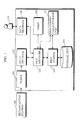
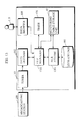
- Fig. 1 is a block diagram of a digital broadcast receiving apparatus in a first embodiment relating to the present invention.
- the digital broadcast receiving apparatus includes a tuner 101, a data decoder 102, a file manager 103, a file system 104, a storage unit 105, a timer 106, a timer monitoring table storage unit 107 and a data browser 108.
- a decoder, speaker and the like used for reproducing program data (audio data broadcast as digital radio) transmitted from the broadcasting station 109 are not the subject of the present invention, so such components will be omitted from the structure of the digital data broadcast receiving apparatus.
- the broadcasting station 109 transmits broadcast data composed by multiplexing program data and multimedia data.
- the program data is audio data with a similar content to a radio program in the related art.
- This data is compressed using MPEG 1 (Motion Picture Experts Group) encoding format and then broadcast.
- MPEG 1 Motion Picture Experts Group
- multimedia data is data other than audio data for a radio program and is broadcast according to the DAB protocol encoding format.
- Examples of multimedia data are HTML (Hyper Text Markup Language) format data used in WWW (World Wide Web) pages, and images in the TIFF (True Image File Format), JPEG (Joint Photographic Coding Experts Group) and GIF (Graphics Interchange Format) formats.
- Audio data may also be included in the multimedia data, but for the sake of simplicity, the multimedia data in the present embodiment is constructed from HTML and JPEG data and does not include audio data.
- the broadcasting station 109 transmits multimedia data using the DAB protocol.
- the tuner 101 receives broadcast data transmitted by the broadcasting station 109 and sorts it into audio data for radio sound and multimedia data.
- the audio data is forwarded to a specialized decoder (not shown) while the multimedia data is forwarded to the data decoder 102 using a receiver data interface (RDI) protocol (this data is hereafter referred to as 'RDI data' for ease of reference).
- RDI receiver data interface
- the same multimedia data is broadcast repeatedly during a specified period, that is to say, until the expire time is reached.
- the data decoder 102 receives the RDI data forwarded from the tuner 101 and decodes it according to the DAB protocol to obtain MOT data 201.
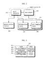
- MOT data 201 is composed of a paired MOT header 202 and MOT body 203, as shown in Fig. 2.
- the MOT body 203 is multimedia data in JPEG or HTML format.
- the MOT header 202 contains the attributes of the MOT body 203, including name, size, trigger time and expire time.
- a timer monitoring table 204 (hereafter referred to as the 'monitoring table') is produced from the MOT data by the file manager 103.
- a directory information table 205 (hereafter referred to as the 'information table') is produced by the file system 104.
- the monitoring table 204 is stored in the monitoring table storage unit 107.
- the information table 205 and the multimedia data 206 written in the MOT body 203 (hereafter referred to as 'files') are stored in the storage unit 105.
- Fig. 3 is a diagram showing the significant information included in the MOT header 202.
- the MOT header 202 includes items of information such as MOT body size 301, data format 302, file name 303, trigger time 304 and expire time 305, all of which are attributes of the MOT body 203.
- the 'size' row 301 shows that the size of data in a file 206 written in the MOT body 203 is 3048 bytes.
- the 'data format' row 302 shows that the data format of the file 206 is JPEG image format.
- the 'filename' row 303 shows that the name of the MOT body 203 is 'Sample.jpg'.
- the 'trigger time' row 304 shows that the time from which the file 206 can be displayed is '12:10'.
- the 'expire time' row 305 similarly shows that the time until which the file 206 can be displayed is '13:00'.
- file name 'Sample.jpg' shown in 'filename' row 303 is also attached to different MOT data, signifying that these MOT data belong to the same sequence of data, so that, when the file 206 of MOT body 203 is updated, the new version of the file is transmitted with the same file name.
- the data decoder 102 notifies the file manager 103 of the obtained MOT data 201, composed of MOT header 202 and MOT body 203.
- the file manager 103 upon receiving a report of the MOT data 201 from the data decoder 102, compares the expire time 305 written in the MOT header 202 with the current time of the timer 106. If the expire time has passed, the MOT data is discarded, but if the expire time has not been reached, the file manager 103 notifies the file system 104 of the MOT data 201.
- the file manager 103 upon receiving a report of an ID from the file system 104, produces a monitoring table 204 from the content of the MOT header 202.
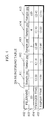
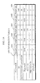
- Fig. 4 shows an example of a monitoring table 204.
- monitoring table 204 filenames from MOT headers and reported IDs in rows 402 and 403 identify the MOT data. Trigger times and expire times are listed in rows 404 and 405. This monitoring table 204 is for files with the filename 'Sample.jpg'.
- the file manager 103 produces the monitoring table 204 and records it in the monitoring table storage unit 107. Furthermore, the file manager refers to the timer 106 at specified intervals, to determine whether one of the trigger times or expire times stored in rows 404 and 405 of the monitoring table has been reached. If a file has reached its trigger time, the file manager 103 instructs the file system 104 to change the 'status' of the file from '0' to '1', while changing the status of another file with the same name from '1' to '2'.
- the file manager 103 deletes the content of the monitoring table 204 relating to this file, and notifies the file system 104 of the filename and ID, to have the content relating to the file deleted from the storage unit 105.
- the file manager 103 also instructs the file system 104 to change the status of a file that had just previously been changed to '2' back to '1', by indicating the filename and ID of the file.
- the file manager 103 receives a report of a file content from the file system 104, the data browser 108 is informed of this content.
- the file system 104 receives a report of the MOT data from the file manager 103, and generates a unique ID from an integer value that is '1' or greater. The file system 104 then informs the file manager 103 of this ID and produces an information table.
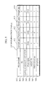
- Fig. 5 shows an example of an information table 205. An information table 205 is produced for all MOT data with a same attached file name 502. The information in the information table 205 is referred to each time the data browser 108 displays a version of the file with the filename 'Sample.jpg'.
- Rows 'filename' 502 and 'ID' 503 in the directory information identify files in the same way as the corresponding rows in the monitoring table 204.
- a 'data storage location' row 504 shows the first block number of a data block in the storage unit 105, where the data written in the MOT body is stored as a file. This block number is written when a file is stored in the storage unit 105.
- a 'file size' row 505 shows the size of files written in HTML or JPEG format in the MOT body.
- a 'next ID' row 506 shows the ID of the next file in the sequence to reach its trigger time.
- the next ID of the file with the file name 'Sample.jpg' and an ID '3' is '0', indicating that there is no file that reaches its trigger time after this file.
- the 'previous ID' row 507 shows the ID of the previous file in the sequence to reach its trigger time.
- the previous ID of a file with the file name 'Sample.jpg' and an ID '2' is '0', indicating that there is no file that reaches its trigger time prior to this file.
- a 'status' row 508 shows which one of the files stored in the storage unit 105 can be displayed.
- the 'status' row 508 is established according to the trigger time 304 and the expire time 305 in Fig. 3. These times indicate the start and finish of the specified display period for the file and are written in the MOT header 202 transmitted from the broadcasting station 109.
- '0' Prior to a trigger time of a file the value '0' is written in the 'status' row 508. During the specified display period, '1' is written in the 'status' row 508 to indicate the most recent file version (the file that has most recently reached its trigger time) and '2' is written for all other files.
- '0' indicates that display of a file is impossible
- '1' that the file is to receive display priority
- '2' that the file may be displayed after the file for which '1' is recorded, if a user instruction is received.
- the file system 104 When producing an information table 205, the file system 104 receives a report of MOT data from the file manager 103, reads file name 303 from the MOT header 202 and records this filename 'Sample.jpg' in the directory information 'filename' row 502. The file system 104 records the generated ID in 'ID' row 503. Next, the file system 104 reads the size 301 from the MOT header 202 and records it in the 'file size' row 505. If there are no other files with the filename 'Sample.jpg', the file system 104 records '0' in the 'next ID' row 506 and the 'previous ID' row 507 and records a default value '0' in the 'status' row 508. The content of the file from MOT body 203 is stored in storage unit 105, and the first block number recorded in the 'data storage location' row 504. The information table is then similarly stored in storage unit 105.
- the file system 104 compares a trigger time 304 recorded in the reported MOT header 202 with a trigger time already recorded in row 404 of the monitoring table 204. The file system 104 then writes '0' in row 507 as the previous ID for the file that is the earlier of the two to reach its trigger time. The ID of this file is then written in row 507 as the previous ID for the file that is the later to reach its trigger time. Conversely, the file system 104 writes '0' in row 506 as the next ID for the file that is the later to reach its trigger time. The ID of this file is then written in row 506 as the next ID of the file that is the earlier to reach its trigger time.
- the file system 104 checks whether the trigger time 304 recorded in the reported MOT header 202 fits in between any trigger times recorded in the monitoring table 204 and alters the 'next ID' row 506 and 'previous ID' row 507 accordingly.
- This drawing includes five versions of a file with the filename 'Sample.jpg', and graphically shows whether the files 412, 411, 414, 413 and 415 in the monitoring table 204 of Fig. 4 can be displayed or not.
- the horizontal axis of Fig. 6 is a time axis, while the IDs '2', '1', '4', '3', and '100' shown on the left side of the drawing identify the files 412, 411, 414, 413 and 415 respectively.
- the file 412 is stored in the storage unit 105 at 10:30, the file 411 at 10:31, the file 414 at 10:32, the file 413 at 10:33 and the file 415 at 12:50.
- the information table 205 in Fig. 5 shows the situation at a time T1. In this case, if the user selects a file with the filename 'Sample.jpg', the most recent version of the file, file 413, is displayed.
- the file manager 103 notifies the file system 104 of a MOT header 701, shown in Fig. 7, together with its MOT body.
- the file system 104 generates an ID '100', informs the file manager 103 of the ID '100', has the file stored in the storage unit 105 and alters the information table 205.
- Fig. 8 shows an altered section 801 of the information table 205 in Fig. 5.
- the file 415 with the ID '100' has already passed its trigger time of 12:45, and so its status in row 508 is '1'.
- There is no file with a trigger time after that of the file 415 so the next ID in row 506 is '0'.
- the file with a trigger time immediately before the file 415 is file 413.
- This file 413 has the ID '3', so the previous ID of the file 415 written in row 507 is '3'.
- the next ID of the file 413 in row 506 is altered to '100' and the status in row 508 from '1' to '2'.
- the file system 104 receives a report from the file manager 103 that the file 415 has reached its expire time. Then, the file system 104 deletes the file 415 from the storage unit 105 and the part of section 801 relating to file 415 from the information table 205, and then returns the information table 205 to its former state.
- the file system 104 searches information tables such as 205 stored in the storage unit 105 and reads the value of the 'data storage location' row 504 corresponding to the files with the status '1'.
- the file system 104 reads all corresponding files (multimedia data) and notifies the file manager 103 of them one by one.
- the file system 104 Upon receiving an indication of a previous file from the file manager 103, the file system 104 retrieves the previous ID of the file being displayed from row 507 in the information table 205, and reads the data storage location of the file with this ID. The file system 104 then reads the file from this data storage location in the storage unit 105 and reports it to the file manager 103.
- the file system 104 retrieves a next ID from row 506 of the information table 205 and reads a data storage location of a file with this ID. The file system 104 then reads a file from this location and reports it to the file manager 103.
- the file system 104 reads the value for the data storage location of the file, reads the file and notifies the file manager 103.
- the storage unit 105 is composed of RAM (Random Access Memory) or the like and stores the information tables such as table 205 produced by the file system 104, as well as files such as files 411 to 414 and 901 shown in Fig. 9.
- the files 411 to 414 are multimedia data written in a MOT body.
- the files are stored in JPEG format, and Fig. 9 shows their display content.
- files such as 901 are multimedia files written in a MOT body.
- the file 901 is stored using HTML format, and Fig. 9 shows its display content. It should be noted that this drawing corresponds to the time T1.
- arrows such as 902 illustrate the content of the 'next ID' 506 and 'previous ID' 507 rows in the information table 205, showing the link targets for files (the links between various files).
- the file system 104 deletes the content of files that have exceeded their specified display time (passed the expire time) and updates the content of the information table 205 according to the order in which trigger times are reached.
- the timer 106 measures the time. Note that accurate timing may be ensured having the broadcasting station 109 send a standard clock.
- the monitoring table storage unit 107 is composed of RAM or the like.
- the file manager 103 stores the monitoring table 204 in monitoring table storage unit 107. Data is added to or deleted from the monitoring table 204 when a report of a new MOT body is received or when a file has passed its expire time.
- the data browser 108 includes a display unit composed of a liquid crystal display or similar, and an input device, such as a jog dial. Upon receiving data in JPEG or HTML format the data browser 108 converts the received data into display data and displays it on the display unit.
- the data browser 108 When activated by a user 110, the data browser 108 gives an initial display instruction to the file system 104 via the file manager 103.
- the data browser 108 upon receiving indication of a file selected using the jog dial or similar, deletes display data other than that for the indicated file, and displays the display data from the indicated file at normal size.
- the data browser 108 indicates this change to the file system 104 via the file manager 103. If the instruction is for a change to a previous version the data browser 108 instructs the file system 104 to retrieve a previous file. Similarly, if the instruction is for a change to a next version, the data browser 108 instructs the file system 104 to retrieve a next file.
- the data browser 108 Upon receiving file content from the file system 104 via the file manager 103, the data browser 108 converts the file content to display data. The data browser 108 then deletes any display data that is being displayed and displays the converted file content on the display unit.
- the data browser 108 receives the content of a plurality of files, it reduces the size of the images contained in each file so that all of the display data can be displayed on one screen by the display unit. The content of the files is then displayed.
- the storage unit 105 stores an information table for files with the filename 'Sample.htm'.
- the file with a status '1' at the time T1 is the file 901 shown in Fig. 9.
- the display data 1001 shows the content of a file with the filename 'Sample.jpg' and the display data 1002 shows the content of a file with the filename 'Sample.htm'.
- the display data 1001 is displayed at normal size, as shown in Fig. 10B.
- the display data 1003 for the most recent previous version of the 'Sample.jpg' file, that is file 414, is displayed, as in Fig. 10C.
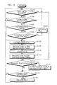
- Fig. 11 shows the operation that takes place when multimedia data sent from the broadcasting station 109 using the DAB protocol is received by the tuner 101 and RDI data transmitted from the tuner 101 is decoded by the data decoder 102 according to a specified protocol to produce MOT data, this data is then reported to the file manager 103.
- Fig. 12 shows the operation that takes place when an instruction from the user 110 is transmitted from the data browser 108 to the file manager 103.
- Step S1102 the file manager 103 first determines whether a MOT data report has been received. If a report has not been received, the routine moves to Step S1114. If a report has been received, at Step S1104 the file manager 103 compares the expire time written in the MOT header with the current time of the timer 106. If the expire time has passed the file manager 103 discards the MOT data and returns to Step S1102. If the expire time has not passed, the file manager 103 notifies the file system 104 of the MOT data.
- the file system 104 When the file system 104 receives a report of the MOT data, at Step S1106 it generates a file ID and reports the ID to the file manager 103.
- Step S1108 the file manager 103 reads the ID, and the filename, trigger time and expire time written in the MOT header of the MOT data and produces or alters a monitoring table, which is then stored.
- the file system 104 stores the file written in the MOT body of the reported MOT data in the storage unit 105. Then, at Step S1112, the file system 104 produces or alters an information table using the content of the MOT header and the monitoring table. The information table is then stored in the storage unit 105.
- Step S1114 the file manager 103 compares the trigger time in the monitoring table and the current time of the timer at specified intervals of, for example, one minute, and determines whether there is a file that has reached its trigger time. If there is such a file, the file manager 103 notifies the file system 104, but if not the routine moves to Step S1118.
- Step S1116 the file system 104 alters the 'status' row of the information table.
- Step S1118 the file manager 103 similarly determines, at specified intervals, whether there is a file that has reached its expire time. If there is such a file, the file manager 103 instructs the file system 104 to delete it, but if not the routine returns to Step S1102.
- Step S1120 the file system 104 deletes the file with the ID indicated by the file manager 103 and the corresponding information in the information table, and the routine returns to Step S1102.
- Step S1202 the file system 104 receives an initial display instruction from the data browser 108 via the file manager 103, searches the information tables and reads all the files with the status '1'. The file system then notifies the data browser 108.
- Step S1204 the data browser 108 reduces the size of display images contained in the files, if necessary, so that they can be displayed on one screen.
- Step S1206 When an instruction from a user selecting one of the files is received, that file is displayed at normal size, at Step S1206.
- the data browser 108 determines whether a version change instruction has been received from a user. If an instruction has not been received, at Step S1210 the file system 104 detects whether there has been a change in the file having the status '1' in the information table for files with the same filename. If there is a change in the version with the status '1', the file system 104 reads the updated version of the file and informs the data browser 108 via the file manager 103. If there is no change, the routine returns to Step S1208.
- Step S1212 the data browser 108 displays the file indicated by the file system 104 and the routine returns to Step S1208.
- the data browser 108 determines whether the instruction is for a change to a previous version of the file at Step S1214. If so, the data browser requests the file system 104 for the previous file via the file manager 103.
- the file system 104 retrieves the previous ID of the file at present being displayed from the information table, reads the file with this ID and sends it to the data browser 108 via the file manager 103.
- the data browser 108 displays the indicated file at Step S1216 and the routine returns to Step S1208.
- Step S1214 if the request is not for a previous file, the data browser 108 requests the file system 104 for a next file.
- the file system 104 retrieves the next ID of the file at present being displayed, reads the file with this ID and sends it to the data browser 108.
- the data browser 108 displays the indicated file at Step 1218 and the routine returns to Step S1208.
- Fig. 13 is a block diagram showing a second embodiment of a digital data broadcast receiving apparatus relating to the present invention.
- Components identical to those in the first embodiment have the same reference numerals. Explanation of these components is omitted, so the following explanation deals only with those components unique to the present embodiment.
- updated versions of a file with the same filename obtained from the data decoder 102 are all stored in the storage unit 105.
- the number of file versions is limited to a predetermined number.
- a file system 1301 has the following features, in addition to the structure of the file system 104 in the first embodiment.
- the file system 1301 stores a number of unique IDs 'N', as a predetermined maximum number of IDs. These IDs are given to MOT data 201 with the same attached filename.
- the file system 1301 receives a report of the MOT data 201 from a file manager 1302, it reads the filename from the MOT header 202.
- the file system 1301 determines whether the number of files in the information table is less than the maximum 'N'. If the number of files is less than 'N', the file system 1301 informs the file manager 1302 of the generated ID. If the number of files is 'N' or more, the file system 1301 gives an ID '-1' report to the file manager 1302.
- the file manager 1302 has the following structure, in addition to that of the file manager 103 in the first embodiment.
- the file manager 1302 receives a report of the MOT data 201 from the data decoder 102 and notifies the file system 104 of this data. Then, if an ID '-1' report has been received from the file system 1301, the file manager 1302 discards the MOT data 201.
- the 'filename' row 1401 of the information table I shows that five files, 1402 to 1406, with the filename 'Sample.jpg' are already stored in the storage unit 105.
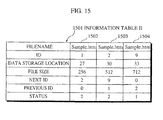
- the 'filename' row 1501 of the information table II shows that three files, 1502 to 1504, with the filename 'Sample.htm' are already stored in the storage unit 105.
- the file system 1301 On receiving a report of an updated version of the MOT data (file) for 'Sample.jpg', via the file manager 1302 from the data decoder 103, the file system 1301 refers to the 'filename' row 1401 of the information table I. Since the number of 'Sample.jpg' files has already reached the maximum '5', the file system 1301 gives an ID '-1' report to the file manager 1302. When the file manager 1302 receives this ID '-1' report, it discards the updated version of the MOT data.
- a file indicated to the file system 1301 is 'Sample.htm' file
- the file system 1301 refers to the 'filename' row 1501 of the information table II. Since the number of 'Sample.htm' files is three, which is less than the maximum '5', an ID is generated and indicated to the file manager 1302.
- a file 1406 shown in Fig. 14 has reached its expire time of 12:55, the file itself and the corresponding content of the information table II are deleted from the storage unit 105.
- the file system 1301 receives a report of an updated version of the file 'Sample.jpg', the number of files is less than the maximum '5', so the file system 1301 generates an ID and notifies the file manager 1302.
- Step S1104 if the expire time has not been reached, the file system 1301 determines at Step 1602 whether an information table for files with the same filename as the indicated file exists. If such a table does not exist, the routine moves to Step 1106, but if such a table exists, the file system 1301 determines at Step 51604 whether the number of files is less than the maximum 'N'. If the number is less than 'N', the routine moves to Step S1106, but if it is more than 'N', the indicated file is discarded at Step S1606 and the routine returns to Step S1102.
- a file that could not be stored the first time it was received due to the number of files already having reached the maximum 'N' may be stored in the storage unit 105 when it is received later, provided that, in the meantime, a file with the same filename stored in the storage unit 105 has reached its expire time and been deleted.
- Fig. 17A shows N files with the same filename, which are stored in the storage unit 105. Files are shown with numbers An showing the order in which they reach their trigger time. In the drawing, k files in the information table have the status '2'. Here, if updated files with the same filename are received in sequence, files are deleted from the storage unit 105 one after the other starting with the file with the lowest An number (the file that was the first to reach its trigger time). Deleted files are illustrated by dotted lines in the drawing. Here, processing takes place on the assumption that the older the file version, the lower its value.
- a file system deletes the content corresponding to a file with the previous ID '0' from the information table stored in the storage unit 105, and alters the previous ID of the file whose ID was recorded as the next ID of the aforementioned file to '0'.
- the file system deletes the file with the previous ID '0' from the storage unit 105 and generates an ID for the newly-received MOT data, which is then indicated to the file manager.
- the file system notifies the file manager of the deleted file and instructs the file manager to delete content corresponding to this file from the monitoring table.
- the file system stores the MOT body of the MOT data indicated by the file manager in the storage unit 105 and records a column for the newly-stored file in the corresponding information table, with reference to the monitoring table stored in the monitoring table storage unit 107.
- the file manager Upon receiving a report of the ID of the deleted file, the file manager deletes the content of the relevant column in the monitoring table corresponding to the file.
- Fig. 17B shows a second alternative.
- the file system deletes files with the same filename having an information table status of '2' at random.
- files with the An numbers 2, 4 and so on are deleted.
- the file system generates random numbers between 1 and k and deletes files with the corresponding An numbers. Processing takes place on the assumption that the old file versions are of an equally low value.
- file system uses the same processing as that in the first alternative to alter the information table, delete old files and store new files.
- Fig. 17C shows a third alternative.
- the file system calculates the An number for the n th file to be deleted according to the following formula: As a result, the first four files to be deleted are, in order, 1, 3, 6 and 10.
- the above embodiments of the present invention relate to a digital data broadcast receiving apparatus with a structure as shown in the block diagrams Figs. 1 and 13.
- a similar effect to that of this digital data broadcast receiving apparatus can be achieved by recording a program possessing the functions of each of the components shown in the block diagrams onto a computer-readable recording medium and installing the recording medium into a receiving apparatus without these functions, which then reads and executes the program.
- multimedia data is multiplexed together with program data for a program broadcast and transmitted repeatedly from a radio broadcasting station.
- the form of the transmission is not limited to this one and cables or radio waves may be used, so that the multimedia data may be transmitted together with program data from a television broadcasting station, or communicated via a public network from an Internet server.
- multimedia data transmitted from a radio broadcasting station is described as being in HTML or JPEG format, so that the trigger time 304 and the expire time 305 refer to display initialization and completion.
- the multimedia data may, for instance, be output as audio instead of being displayed.
- the display initialization time and completion time become output initialization time and completion time.
Abstract
Description
- The present invention relates to a digital data receiving apparatus for receiving and outputting multimedia data.
- Recently, there has been a movement towards actual digital television and radio broadcasting. Digital broadcasting allows multichannels to be used, so that other data can be freely multiplexed and broadcast with digitized programs.
- In European countries such as the UK and Sweden broadcasting of digital radio employing the DAB (Digital Audio Broadcasting) format is already in operation. DAB was initiated by the EUREKA No. 147 Working Group (the European Research Coordinating Agency).
- In the DAB broadcast protocol, data other than program broadcasts is transmitted as MOT (Multimedia Object Transfer protocol) data.
- MOT data is composed of a MOT body, which represents the actual data, and a MOT header, which indicates the content of the MOT body. The MOT header includes information such as a file name for the MOT data and a trigger time, indicating the time at which processing of the MOT data should begin.
- At present, however, this trigger time is not effectively used, so that when a broadcast receiving apparatus receives MOT data, the data represented by the MOT body is reproduced without reference to the trigger time.
- Another problem occurs when receiving sequences of MOT data where a same filename is given in the MOT header for data of different MOT bodies. If the MOT data is stored by filename to be used later, distinguishing the MOT data purely by filename is extremely difficult.
- An object of the present invention is to provide a digital data receiving apparatus capable of using the trigger time effectively to make good use of data included in a MOT body. A further object is to provide a terminal and receiving method capable of using received data effectively in a digital data communication environment that repeatedly transmits multimedia data with an attached expiry time. Here, the digital data communicating environment is not limited to the DAB format.
- The objects of the present invention are achieved by a digital data receiving apparatus that receives multimedia data via a receiving unit and stores it in a storage unit. A data management table producing unit then extracts specified access period information written in each piece of received multimedia data and divides the received multimedia data into at least one group. Furthermore, when each multimedia data group is stored into the storage unit, the data management table producing unit determines an access order according to a chronological order of the extracted specified access period information, produces a data management table in which the determined access order is written, and has the data management table stored in the storage unit. An indication receiving unit receives an indication from a user. Then, a multimedia data reading unit reads a piece of multimedia data stored in the storage unit according to the access order written in the data management table. Finally an output unit converts the piece of multimedia data read by the multimedia reading unit into a reproduction signal, which it then outputs. In this structure, output instructions can be received from a user during a time specified as a specified access period by a multimedia data provider, so that multimedia data can be output effectively.
- The data management unit may also include an identifier attaching unit. When multimedia data is stored into the storage unit, the identifier attaching unit attaches a unique identifier to identify each piece of multimedia data in a multimedia data group. Here, each piece of multimedia data in the multimedia data group has the same attached name, and identifiers are used to selectively read one piece of multimedia data from the multimedia data group. In this structure, even if the plurality of pieces of multimedia data in each group (sequence) of multimedia data have the same attached name, each can be identified by an identifier. Thus, when an output instruction is received from a user, multimedia data can be output effectively during the specified access period.
- The data management table producing unit may further list access availability statuses showing the access availability of each piece of multimedia data in the data management table, according to the specified access period information. Here, the specified access period information is represented by times showing the start time and end time. The digital data receiving apparatus further includes a timer, and an updating unit. This updating unit changes the access availability status of any one of the pieces of multimedia data to a first access availability status when a start time is reached, to a second access availability status when an end time is reached, and from the first access availability status to a third access availability status when the start time for another piece of multimedia information is reached. In this structure, the access availability statuses for each group of multimedia data can be sorted and written into a corresponding data management table by referring to the start and end of the specified access period. In this way, the order of priority for the multimedia data to be output is decided in advance.
- The updating unit may also include a deletion unit, which deletes pieces of multimedia data that have reached the second access availability status from the storage unit. In this structure, multimedia data that has exceeded its specified access period is deleted, so that a memory in a storage unit requires only limited resources.
- The multimedia data reading unit may also include a first reading unit, which reads all pieces of multimedia data for which the first access availability status is shown in the data management table. Here, when the indication receiving unit receives a selection indication for a reproduced piece of multimedia data from a user, the output unit outputs a reproduction signal only for the selected piece of multimedia data. In this structure, the most recent piece of data for each group is output, and when the user selects a desired group, only the most recent piece of multimedia data of the selected group is output.
- The multimedia data reading unit may further include a second reading unit, for reading another piece of multimedia data from the same group as the selected piece of multimedia data, according to a change indication. Here, the indication receiving unit receives the change indication from a user, and reports it to the second reading unit. In this structure, a user can indicate a different version of multimedia data belonging to the selected group and cause it to be output.
- The second reading unit may also receive the change indication and read a piece of multimedia data according to the access order in the data management table for the multimedia data group of the selected piece of multimedia data. The access order is shown in the data management table by having each piece of multimedia data associated with identifiers of link targets. In this structure, each piece of multimedia data can be linked to its link targets in chronological order, so that a user can return from a new version to an old version, or alternatively cause a new version to be output following an old version.
- The digital data receiving apparatus may also include a multimedia data discarding unit. This unit sets in advance a maximum number of pieces of multimedia data for any multimedia group in the storage unit. It then discards a piece of multimedia data received by the receiving unit if the maximum number of pieces of multimedia data for the multimedia data group of the received piece of data are already stored in the storage unit. This structure prevents the storage of large quantities of the multimedia data for only one group in the storage unit, which would otherwise stop the most recent versions for other multimedia groups from being stored. Instead, multimedia data for each group is stored on an equal basis.
- The digital data receiving apparatus may also include a multimedia data selective deleting unit, for setting in advance a maximum number of pieces of multimedia data for any multimedia group in the storage unit. When a new piece of multimedia data of a multimedia data group for which the maximum number of pieces of data is already stored in the storage unit is received, the multimedia selective deleting unit selectively deletes one of the pieces of multimedia data stored in the storage unit with a third access availability status. The new piece of multimedia data is then stored in the storage unit. In this structure, multimedia data for each group can be stored on an equal basis until the maximum number of pieces is reached. If a new version of multimedia data for a certain group is received, and the number of stored pieces of data in that group has already reached the maximum number, an old version of multimedia data from that group is selected and deleted, so that the most recent version can be stored. As a result, a user can obtain an output with the most recent information.
- The multimedia data selective deleting unit may also select and delete pieces of data from among the pieces of multimedia data with the third access availability status, starting with the piece of multimedia data that was first to reach the first access availability status. In this structure, when the number of stored pieces of multimedia data from a group has reached the maximum number, the oldest version of the multimedia data in the same group is deleted, enabling a newly-received piece of multimedia data to be stored. The value of an old piece of multimedia data is considered to be lower than that of a new piece of multimedia data.
- The multimedia data selective deleting unit may also randomly select and delete pieces of multimedia data from among the pieces of multimedia data with the third access availability status. In this structure, a piece of multimedia data other than the piece of multimedia data to be output is selected at random and deleted, enabling a newly-received piece of multimedia data to be stored. The value of an old piece of multimedia data is generally considered to be lower than that of a newly-received piece of multimedia data, and so an old piece of multimedia data is deleted at random.
- The multimedia data selective deleting unit may also, when deleting n pieces of multimedia data from the storage unit, attach numbers starting from '1' to pieces of multimedia data with the third access availability status. These numbers run in order from the piece of multimedia data with the oldest start time. The multimedia data selective deleting unit selects and deletes pieces of multimedia data with An numbers calculated using the following formula:In this structure, the older a piece of multimedia data, the lower its value is considered to be, so that older pieces of multimedia data have a higher probability of being deleted. Newly-received pieces of multimedia data can be stored in groups and valuable information accumulated.

- The receiving unit receives multimedia data transmitted together with program data from a broadcasting station. Here, the multimedia data is structured according to a MOT (Multimedia Object Transfer protocol) conforming to a DAB (Digital Audio Broadcasting) data broadcast protocol. Therefore, a name and specified access period for the multimedia data are written in a MOT header, and the multimedia data is written in a MOT body. In this structure, multimedia data multiplexed and transmitted with program data from a broadcasting station is received and can be output during an access period specified by the broadcasting station.
- The objects of the present invention may also be achieved by a digital data receiving method. This method is used in a digital data receiving apparatus that receives multimedia data via a receiving unit and stores the received multimedia data in a storage unit. It includes the following steps. Firstly, in a data management table producing step, specified access period information written in each piece of received multimedia data is extracted and the multimedia data divided into at least one group. When the multimedia data is stored in the storage unit, an access order is determined according to a chronological order of the extracted specified access period information and a data management table in which the determined access order is written is produced. The data management table is then stored in the storage unit. Next, an indication receiving step receives indications from a user. Then, a multimedia data reading step reads a piece of multimedia data stored in the storage unit according to the access order written in the data management table. Finally an output step converts the piece of multimedia data read by the multimedia reading step into a reproduction signal, which it then outputs. In this structure, output instructions are received from a user during a time period specified by the multimedia data provider, so that the multimedia data can be output effectively.
- The objects of the present invention may also be achieved by a computer-readable recording medium, used in a digital data receiving apparatus that receives multimedia data via a receiving unit and stores the received multimedia data in a storage unit. Here, the computer-readable recording medium records a program including the following functions. A data management table producing unit extracts specified access period information written in each piece of received multimedia data and divides the received multimedia data into at least one group. When each multimedia data group is stored in the storage unit, the data management table producing unit determines an access order according to a chronological order of the extracted specified access period information and produces a data management table in which the determined access order is written. The data management table is then stored in the storage unit. An indication receiving unit receives indications from a user. Then, a multimedia data reading unit reads multimedia data stored in the storage unit according to the access order written in the data management table. Finally an output unit converts the piece of multimedia data read by the multimedia reading unit into a reproduction signal and outputs it. In this structure, the recording medium is used by a digital data receiving apparatus that does not have a function for referring to the specified access period, enabling an output instruction made by a user to be received during a time specified by the provider, so that the multimedia data can be output effectively.
- These and other objects, advantages and features of the invention will become apparent from the following description thereof taken in conjunction with the accompanying drawings which illustrate a specific embodiment of the invention. In the drawings:
- Fig. 1 is a block diagram of a digital data broadcast receiving apparatus in a first embodiment of the present invention;
- Fig. 2 is a diagram showing MOT data reported to a file manager in the first embodiment;
- Fig. 3 is a diagram showing items written in a MOT header of the MOT data in the first embodiment;
- Fig. 4 is a diagram showing an example of a monitoring table produced by the file manager in the first embodiment and stored in a monitoring table storage unit;
- Fig. 5 is a diagram showing an example of the content of an information table produced by a file system in the first embodiment and stored, with files, in a storage unit;
- Fig. 6 is a time chart used to explain a 'status' row in the information table of the first embodiment;
- Fig. 7 is a diagram showing an example of a MOT header reported to the file system in the first embodiment;
- Fig. 8 is a diagram showing an information table in the first embodiment, which has been changed by the file system in accordance with the reported MOT header shown in Fig. 7;
- Fig. 9 is a diagram showing an example of the content of files stored in the storage unit in the first embodiment;
- Fig. 10 is a diagram showing multimedia data displayed by a data browser in the first embodiment;
- Fig. 11 is a flowchart showing the operation for producing the monitoring table and the information table in the first embodiment;
- Fig. 12 is a flowchart explaining the operation of the data browser in the first embodiment;
- Fig. 13 is a block diagram of a digital data broadcast receiving apparatus in the second embodiment of the present invention;
- Fig. 14 is a diagram showing an example of an information table I stored in a storage unit in the second embodiment;
- Fig. 15 is a diagram showing an example of an information table II stored in the storage unit in the second embodiment;
- Fig. 16 is a flowchart explaining the operation of the second embodiment; and
- Fig. 17 is a diagram showing the selection and deletion of files stored in the storage unit of an alternative example of the second embodiment.
-
- The following is an explanation of embodiments of a digital broadcast receiving apparatus relating to the present invention, with reference to the drawings.
- Fig. 1 is a block diagram of a digital broadcast receiving apparatus in a first embodiment relating to the present invention.
- The digital broadcast receiving apparatus includes a
tuner 101, adata decoder 102, afile manager 103, afile system 104, astorage unit 105, atimer 106, a timer monitoringtable storage unit 107 and adata browser 108. - It should be noted that a decoder, speaker and the like used for reproducing program data (audio data broadcast as digital radio) transmitted from the
broadcasting station 109 are not the subject of the present invention, so such components will be omitted from the structure of the digital data broadcast receiving apparatus. - The
broadcasting station 109 transmits broadcast data composed by multiplexing program data and multimedia data. - Here, the program data is audio data with a similar content to a radio program in the related art. This data is compressed using MPEG 1 (Motion Picture Experts Group) encoding format and then broadcast.
- Here, the multimedia data is data other than audio data for a radio program and is broadcast according to the DAB protocol encoding format. Examples of multimedia data are HTML (Hyper Text Markup Language) format data used in WWW (World Wide Web) pages, and images in the TIFF (True Image File Format), JPEG (Joint Photographic Coding Experts Group) and GIF (Graphics Interchange Format) formats.
- Audio data may also be included in the multimedia data, but for the sake of simplicity, the multimedia data in the present embodiment is constructed from HTML and JPEG data and does not include audio data.
- The
broadcasting station 109 transmits multimedia data using the DAB protocol. - The
tuner 101 receives broadcast data transmitted by thebroadcasting station 109 and sorts it into audio data for radio sound and multimedia data. The audio data is forwarded to a specialized decoder (not shown) while the multimedia data is forwarded to thedata decoder 102 using a receiver data interface (RDI) protocol (this data is hereafter referred to as 'RDI data' for ease of reference). - Here, the same multimedia data is broadcast repeatedly during a specified period, that is to say, until the expire time is reached.
- The
data decoder 102 receives the RDI data forwarded from thetuner 101 and decodes it according to the DAB protocol to obtainMOT data 201. -
MOT data 201 is composed of a pairedMOT header 202 andMOT body 203, as shown in Fig. 2. TheMOT body 203 is multimedia data in JPEG or HTML format. TheMOT header 202 contains the attributes of theMOT body 203, including name, size, trigger time and expire time. - A timer monitoring table 204 (hereafter referred to as the 'monitoring table') is produced from the MOT data by the
file manager 103. A directory information table 205 (hereafter referred to as the 'information table') is produced by thefile system 104. The monitoring table 204 is stored in the monitoringtable storage unit 107. The information table 205 and themultimedia data 206 written in the MOT body 203 (hereafter referred to as 'files') are stored in thestorage unit 105. - Fig. 3 is a diagram showing the significant information included in the
MOT header 202. TheMOT header 202 includes items of information such asMOT body size 301,data format 302,file name 303,trigger time 304 and expiretime 305, all of which are attributes of theMOT body 203. - The 'size'
row 301 shows that the size of data in afile 206 written in theMOT body 203 is 3048 bytes. The 'data format'row 302 shows that the data format of thefile 206 is JPEG image format. The 'filename'row 303 shows that the name of theMOT body 203 is 'Sample.jpg'. The 'trigger time'row 304 shows that the time from which thefile 206 can be displayed is '12:10'. The 'expire time'row 305 similarly shows that the time until which thefile 206 can be displayed is '13:00'. - It should be noted that the file name 'Sample.jpg' shown in 'filename'
row 303 is also attached to different MOT data, signifying that these MOT data belong to the same sequence of data, so that, when thefile 206 ofMOT body 203 is updated, the new version of the file is transmitted with the same file name. - The
data decoder 102 notifies thefile manager 103 of the obtainedMOT data 201, composed ofMOT header 202 andMOT body 203. - The
file manager 103, upon receiving a report of theMOT data 201 from thedata decoder 102, compares the expiretime 305 written in theMOT header 202 with the current time of thetimer 106. If the expire time has passed, the MOT data is discarded, but if the expire time has not been reached, thefile manager 103 notifies thefile system 104 of theMOT data 201. - The
file manager 103, upon receiving a report of an ID from thefile system 104, produces a monitoring table 204 from the content of theMOT header 202. Fig. 4 shows an example of a monitoring table 204. - In the monitoring table 204, filenames from MOT headers and reported IDs in
rows rows - The
file manager 103 produces the monitoring table 204 and records it in the monitoringtable storage unit 107. Furthermore, the file manager refers to thetimer 106 at specified intervals, to determine whether one of the trigger times or expire times stored inrows file manager 103 instructs thefile system 104 to change the 'status' of the file from '0' to '1', while changing the status of another file with the same name from '1' to '2'. If a file has reached its expire time, thefile manager 103 deletes the content of the monitoring table 204 relating to this file, and notifies thefile system 104 of the filename and ID, to have the content relating to the file deleted from thestorage unit 105. Here, if the status of the file is '1', thefile manager 103 also instructs thefile system 104 to change the status of a file that had just previously been changed to '2' back to '1', by indicating the filename and ID of the file. - In addition, each time the
file manager 103 receives an initial display indication, or indication of a previous or next file from thedata browser 108, this information is passed to thefile system 104. - Also, when the
file manager 103 receives a report of a file content from thefile system 104, thedata browser 108 is informed of this content. - The
file system 104 receives a report of the MOT data from thefile manager 103, and generates a unique ID from an integer value that is '1' or greater. Thefile system 104 then informs thefile manager 103 of this ID and produces an information table. Fig. 5 shows an example of an information table 205. An information table 205 is produced for all MOT data with a same attachedfile name 502. The information in the information table 205 is referred to each time thedata browser 108 displays a version of the file with the filename 'Sample.jpg'. - Rows 'filename' 502 and 'ID' 503 in the directory information identify files in the same way as the corresponding rows in the monitoring table 204. A 'data storage location'
row 504 shows the first block number of a data block in thestorage unit 105, where the data written in the MOT body is stored as a file. This block number is written when a file is stored in thestorage unit 105. - A 'file size'
row 505 shows the size of files written in HTML or JPEG format in the MOT body. - When each file ID is arranged in order starting from the file in
row 404 with the earliest trigger time, a 'next ID'row 506 shows the ID of the next file in the sequence to reach its trigger time. Here, the next ID of the file with the file name 'Sample.jpg' and an ID '3' is '0', indicating that there is no file that reaches its trigger time after this file. - Similarly, when each file ID is arranged in order from the file in
row 404 with the earliest trigger time, the 'previous ID'row 507 shows the ID of the previous file in the sequence to reach its trigger time. Here, the previous ID of a file with the file name 'Sample.jpg' and an ID '2' is '0', indicating that there is no file that reaches its trigger time prior to this file. - A 'status'
row 508 shows which one of the files stored in thestorage unit 105 can be displayed. The 'status'row 508 is established according to thetrigger time 304 and the expiretime 305 in Fig. 3. These times indicate the start and finish of the specified display period for the file and are written in theMOT header 202 transmitted from thebroadcasting station 109. - Prior to a trigger time of a file the value '0' is written in the 'status'
row 508. During the specified display period, '1' is written in the 'status'row 508 to indicate the most recent file version (the file that has most recently reached its trigger time) and '2' is written for all other files. - Here, '0' indicates that display of a file is impossible, '1' that the file is to receive display priority, and '2' that the file may be displayed after the file for which '1' is recorded, if a user instruction is received.
- When producing an information table 205, the
file system 104 receives a report of MOT data from thefile manager 103, readsfile name 303 from theMOT header 202 and records this filename 'Sample.jpg' in the directory information 'filename'row 502. Thefile system 104 records the generated ID in 'ID'row 503. Next, thefile system 104 reads thesize 301 from theMOT header 202 and records it in the 'file size'row 505. If there are no other files with the filename 'Sample.jpg', thefile system 104 records '0' in the 'next ID'row 506 and the 'previous ID'row 507 and records a default value '0' in the 'status'row 508. The content of the file fromMOT body 203 is stored instorage unit 105, and the first block number recorded in the 'data storage location'row 504. The information table is then similarly stored instorage unit 105. - If a file with the same filename 'Sample.jpg' is already recorded in an information table 205, the
file system 104 compares atrigger time 304 recorded in the reportedMOT header 202 with a trigger time already recorded inrow 404 of the monitoring table 204. Thefile system 104 then writes '0' inrow 507 as the previous ID for the file that is the earlier of the two to reach its trigger time. The ID of this file is then written inrow 507 as the previous ID for the file that is the later to reach its trigger time. Conversely, thefile system 104 writes '0' inrow 506 as the next ID for the file that is the later to reach its trigger time. The ID of this file is then written inrow 506 as the next ID of the file that is the earlier to reach its trigger time. - If a plurality of files with the filename 'Sample.jpg' are already recorded in an information table 205, the
file system 104 checks whether thetrigger time 304 recorded in the reportedMOT header 202 fits in between any trigger times recorded in the monitoring table 204 and alters the 'next ID'row 506 and 'previous ID'row 507 accordingly. - The following explains how the content of the information table 205 changes over time with reference to the MOT data time chart of Fig. 6. This drawing includes five versions of a file with the filename 'Sample.jpg', and graphically shows whether the
files - The horizontal axis of Fig. 6 is a time axis, while the IDs '2', '1', '4', '3', and '100' shown on the left side of the drawing identify the
files file 412 is stored in thestorage unit 105 at 10:30, thefile 411 at 10:31, thefile 414 at 10:32, thefile 413 at 10:33 and thefile 415 at 12:50. - At a time T0, which is prior to the trigger time 12:10 of the
file 412, '0' is written in the 'status'row 508 of the information table 205 in Fig. 5 for all of thefiles 411 to 414. Here, if a user tries to display a file with the filename 'Sample.jpg' no file will be displayed, since the present time is outside the display times specified by thebroadcasting station 109. - The information table 205 in Fig. 5 shows the situation at a time T1. In this case, if the user selects a file with the filename 'Sample.jpg', the most recent version of the file, file 413, is displayed.
- At 12:50, the
file manager 103 notifies thefile system 104 of aMOT header 701, shown in Fig. 7, together with its MOT body. Here, thefile system 104 generates an ID '100', informs thefile manager 103 of the ID '100', has the file stored in thestorage unit 105 and alters the information table 205. - Fig. 8 shows an altered
section 801 of the information table 205 in Fig. 5. Thefile 415 with the ID '100' has already passed its trigger time of 12:45, and so its status inrow 508 is '1'. There is no file with a trigger time after that of thefile 415 so the next ID inrow 506 is '0'. The file with a trigger time immediately before thefile 415 isfile 413. Thisfile 413 has the ID '3', so the previous ID of thefile 415 written inrow 507 is '3'. In accordance with this, the next ID of thefile 413 inrow 506 is altered to '100' and the status inrow 508 from '1' to '2'. - At 12:55 the
file system 104 receives a report from thefile manager 103 that thefile 415 has reached its expire time. Then, thefile system 104 deletes thefile 415 from thestorage unit 105 and the part ofsection 801 relating to file 415 from the information table 205, and then returns the information table 205 to its former state. - Furthermore, upon receiving an indication of an initial display from the
file manager 103, thefile system 104 searches information tables such as 205 stored in thestorage unit 105 and reads the value of the 'data storage location'row 504 corresponding to the files with the status '1'. Thefile system 104 reads all corresponding files (multimedia data) and notifies thefile manager 103 of them one by one. - Upon receiving an indication of a previous file from the
file manager 103, thefile system 104 retrieves the previous ID of the file being displayed fromrow 507 in the information table 205, and reads the data storage location of the file with this ID. Thefile system 104 then reads the file from this data storage location in thestorage unit 105 and reports it to thefile manager 103. - Similarly, upon receiving an indication of a next file, the
file system 104 retrieves a next ID fromrow 506 of the information table 205 and reads a data storage location of a file with this ID. Thefile system 104 then reads a file from this location and reports it to thefile manager 103. - Furthermore, when the
status 508 of a file in the information table 205 for the file at present being displayed is altered to '1', thefile system 104 reads the value for the data storage location of the file, reads the file and notifies thefile manager 103. - The
storage unit 105 is composed of RAM (Random Access Memory) or the like and stores the information tables such as table 205 produced by thefile system 104, as well as files such asfiles 411 to 414 and 901 shown in Fig. 9. Thefiles 411 to 414 are multimedia data written in a MOT body. The files are stored in JPEG format, and Fig. 9 shows their display content. Similarly, files such as 901 are multimedia files written in a MOT body. Thefile 901 is stored using HTML format, and Fig. 9 shows its display content. It should be noted that this drawing corresponds to the time T1. Here, arrows such as 902 illustrate the content of the 'next ID' 506 and 'previous ID' 507 rows in the information table 205, showing the link targets for files (the links between various files). - In addition, the
file system 104 deletes the content of files that have exceeded their specified display time (passed the expire time) and updates the content of the information table 205 according to the order in which trigger times are reached. - The
timer 106 measures the time. Note that accurate timing may be ensured having thebroadcasting station 109 send a standard clock. - The monitoring
table storage unit 107 is composed of RAM or the like. Thefile manager 103 stores the monitoring table 204 in monitoringtable storage unit 107. Data is added to or deleted from the monitoring table 204 when a report of a new MOT body is received or when a file has passed its expire time. - The
data browser 108 includes a display unit composed of a liquid crystal display or similar, and an input device, such as a jog dial. Upon receiving data in JPEG or HTML format thedata browser 108 converts the received data into display data and displays it on the display unit. - When activated by a
user 110, thedata browser 108 gives an initial display instruction to thefile system 104 via thefile manager 103. - Furthermore, upon receiving indication of a file selected using the jog dial or similar, the
data browser 108 deletes display data other than that for the indicated file, and displays the display data from the indicated file at normal size. When receiving a file version change instruction, thedata browser 108 indicates this change to thefile system 104 via thefile manager 103. If the instruction is for a change to a previous version thedata browser 108 instructs thefile system 104 to retrieve a previous file. Similarly, if the instruction is for a change to a next version, thedata browser 108 instructs thefile system 104 to retrieve a next file. - Upon receiving file content from the
file system 104 via thefile manager 103, thedata browser 108 converts the file content to display data. Thedata browser 108 then deletes any display data that is being displayed and displays the converted file content on the display unit. - Here, if the
data browser 108 receives the content of a plurality of files, it reduces the size of the images contained in each file so that all of the display data can be displayed on one screen by the display unit. The content of the files is then displayed. - The following is an explanation of the display of files by the
data browser 108 at the time T1. Here, in addition to the information table 205 shown in Fig. 5, thestorage unit 105 stores an information table for files with the filename 'Sample.htm'. In this information table, the file with a status '1' at the time T1 is thefile 901 shown in Fig. 9. - At the time T1 the
data browser 108 is activated by theuser 110. As shown in Fig. 10A, the content of the most recent file versions is displayed. Thedisplay data 1001 shows the content of a file with the filename 'Sample.jpg' and thedisplay data 1002 shows the content of a file with the filename 'Sample.htm'. - If the
user 110 selects thedisplay data 1001 thedisplay data 1001 is displayed at normal size, as shown in Fig. 10B. - Furthermore, if the
user 110 instructs thedata browser 108 to return to the previous version of the file, thedisplay data 1003 for the most recent previous version of the 'Sample.jpg' file, that isfile 414, is displayed, as in Fig. 10C. - Next, the operation of the present embodiment is explained using the flowcharts of Figs. 11 and 12. Fig. 11 shows the operation that takes place when multimedia data sent from the
broadcasting station 109 using the DAB protocol is received by thetuner 101 and RDI data transmitted from thetuner 101 is decoded by thedata decoder 102 according to a specified protocol to produce MOT data, this data is then reported to thefile manager 103. Fig. 12 shows the operation that takes place when an instruction from theuser 110 is transmitted from thedata browser 108 to thefile manager 103. - In Fig. 11, at Step S1102, the
file manager 103 first determines whether a MOT data report has been received. If a report has not been received, the routine moves to Step S1114. If a report has been received, at Step S1104 thefile manager 103 compares the expire time written in the MOT header with the current time of thetimer 106. If the expire time has passed thefile manager 103 discards the MOT data and returns to Step S1102. If the expire time has not passed, thefile manager 103 notifies thefile system 104 of the MOT data. - When the
file system 104 receives a report of the MOT data, at Step S1106 it generates a file ID and reports the ID to thefile manager 103. - At Step S1108 the
file manager 103 reads the ID, and the filename, trigger time and expire time written in the MOT header of the MOT data and produces or alters a monitoring table, which is then stored. - At Step S1110 the
file system 104 stores the file written in the MOT body of the reported MOT data in thestorage unit 105. Then, at Step S1112, thefile system 104 produces or alters an information table using the content of the MOT header and the monitoring table. The information table is then stored in thestorage unit 105. - Next, at Step S1114, the
file manager 103 compares the trigger time in the monitoring table and the current time of the timer at specified intervals of, for example, one minute, and determines whether there is a file that has reached its trigger time. If there is such a file, thefile manager 103 notifies thefile system 104, but if not the routine moves to Step S1118. - At Step S1116 the
file system 104 alters the 'status' row of the information table. - Next, at Step S1118 the
file manager 103 similarly determines, at specified intervals, whether there is a file that has reached its expire time. If there is such a file, thefile manager 103 instructs thefile system 104 to delete it, but if not the routine returns to Step S1102. - At Step S1120 the
file system 104 deletes the file with the ID indicated by thefile manager 103 and the corresponding information in the information table, and the routine returns to Step S1102. - Next, the operation for displaying multimedia data (files) on the
data browser 108 is explained with reference to Fig. 12. - At Step S1202 the
file system 104 receives an initial display instruction from thedata browser 108 via thefile manager 103, searches the information tables and reads all the files with the status '1'. The file system then notifies thedata browser 108. - At Step S1204 the
data browser 108 reduces the size of display images contained in the files, if necessary, so that they can be displayed on one screen. When an instruction from a user selecting one of the files is received, that file is displayed at normal size, at Step S1206. - Next, at
Step 1208, thedata browser 108 determines whether a version change instruction has been received from a user. If an instruction has not been received, at Step S1210 thefile system 104 detects whether there has been a change in the file having the status '1' in the information table for files with the same filename. If there is a change in the version with the status '1', thefile system 104 reads the updated version of the file and informs thedata browser 108 via thefile manager 103. If there is no change, the routine returns to Step S1208. - At Step S1212, the
data browser 108 displays the file indicated by thefile system 104 and the routine returns to Step S1208. - If there is a version change instruction from a user at Step S1208, the
data browser 108 determines whether the instruction is for a change to a previous version of the file at Step S1214. If so, the data browser requests thefile system 104 for the previous file via thefile manager 103. - The
file system 104 retrieves the previous ID of the file at present being displayed from the information table, reads the file with this ID and sends it to thedata browser 108 via thefile manager 103. - The
data browser 108 displays the indicated file at Step S1216 and the routine returns to Step S1208. - At Step S1214, if the request is not for a previous file, the
data browser 108 requests thefile system 104 for a next file. As above, thefile system 104 retrieves the next ID of the file at present being displayed, reads the file with this ID and sends it to thedata browser 108. - The
data browser 108 displays the indicated file at Step 1218 and the routine returns to Step S1208. - Fig. 13 is a block diagram showing a second embodiment of a digital data broadcast receiving apparatus relating to the present invention. Components identical to those in the first embodiment have the same reference numerals. Explanation of these components is omitted, so the following explanation deals only with those components unique to the present embodiment.
- In the first embodiment, updated versions of a file with the same filename obtained from the
data decoder 102 are all stored in thestorage unit 105. In this embodiment, however, the number of file versions is limited to a predetermined number. - A
file system 1301 has the following features, in addition to the structure of thefile system 104 in the first embodiment. Thefile system 1301 stores a number of unique IDs 'N', as a predetermined maximum number of IDs. These IDs are given toMOT data 201 with the same attached filename. When thefile system 1301 receives a report of theMOT data 201 from afile manager 1302, it reads the filename from theMOT header 202. When an information table for the same filename is being produced, thefile system 1301 determines whether the number of files in the information table is less than the maximum 'N'. If the number of files is less than 'N', thefile system 1301 informs thefile manager 1302 of the generated ID. If the number of files is 'N' or more, thefile system 1301 gives an ID '-1' report to thefile manager 1302. - The
file manager 1302 has the following structure, in addition to that of thefile manager 103 in the first embodiment. Thefile manager 1302 receives a report of theMOT data 201 from thedata decoder 102 and notifies thefile system 104 of this data. Then, if an ID '-1' report has been received from thefile system 1301, thefile manager 1302 discards theMOT data 201. - The following is an explanation of an example scenario in which the maximum number of IDs 'N' is set at '5', and the information tables I and II shown in Figs. 14 and 15 are stored in the
storage unit 105. - In Fig. 14, the 'filename'
row 1401 of the information table I shows that five files, 1402 to 1406, with the filename 'Sample.jpg' are already stored in thestorage unit 105. In Fig. 15, the 'filename'row 1501 of the information table II shows that three files, 1502 to 1504, with the filename 'Sample.htm' are already stored in thestorage unit 105. - On receiving a report of an updated version of the MOT data (file) for 'Sample.jpg', via the
file manager 1302 from thedata decoder 103, thefile system 1301 refers to the 'filename'row 1401 of the information table I. Since the number of 'Sample.jpg' files has already reached the maximum '5', thefile system 1301 gives an ID '-1' report to thefile manager 1302. When thefile manager 1302 receives this ID '-1' report, it discards the updated version of the MOT data. - If a file indicated to the
file system 1301 is 'Sample.htm' file, thefile system 1301 refers to the 'filename'row 1501 of the information table II. Since the number of 'Sample.htm' files is three, which is less than the maximum '5', an ID is generated and indicated to thefile manager 1302. - If a
file 1406 shown in Fig. 14 has reached its expire time of 12:55, the file itself and the corresponding content of the information table II are deleted from thestorage unit 105. As a result, when thefile system 1301 receives a report of an updated version of the file 'Sample.jpg', the number of files is less than the maximum '5', so thefile system 1301 generates an ID and notifies thefile manager 1302. By limiting the number of individual files with the same filename in this way, storage of a large number of files of the same type can be prevented, so that other types of files can still be stored, even if the storage capacity available in thestorage unit 105 is limited. - Next, the operation of the present embodiment is explained using the flowchart in Fig. 16. Steps that are identical to those in the operation of the first embodiment have the same step number and are not explained here.
- At Step S1104, if the expire time has not been reached, the
file system 1301 determines atStep 1602 whether an information table for files with the same filename as the indicated file exists. If such a table does not exist, the routine moves to Step 1106, but if such a table exists, thefile system 1301 determines at Step 51604 whether the number of files is less than the maximum 'N'. If the number is less than 'N', the routine moves to Step S1106, but if it is more than 'N', the indicated file is discarded at Step S1606 and the routine returns to Step S1102. - In the present embodiment, a file that could not be stored the first time it was received due to the number of files already having reached the maximum 'N', may be stored in the
storage unit 105 when it is received later, provided that, in the meantime, a file with the same filename stored in thestorage unit 105 has reached its expire time and been deleted. - However, out-of-date file versions that are well past their trigger time are generally of little value. Greater efficiency can therefore be achieved by storing the most recent file versions.
- Here, various alternative examples for the present embodiment are described with reference to Fig. 17. In these examples, when an updated version of a file is received, an old version of the file in the
storage unit 105 is deleted, and the received file is stored in its place. - Fig. 17A shows N files with the same filename, which are stored in the
storage unit 105. Files are shown with numbers An showing the order in which they reach their trigger time. In the drawing, k files in the information table have the status '2'. Here, if updated files with the same filename are received in sequence, files are deleted from thestorage unit 105 one after the other starting with the file with the lowest An number (the file that was the first to reach its trigger time). Deleted files are illustrated by dotted lines in the drawing. Here, processing takes place on the assumption that the older the file version, the lower its value. - In other words, if a MOT data report received from a file manager causes the number of files to exceed the maximum 'N', a file system deletes the content corresponding to a file with the previous ID '0' from the information table stored in the
storage unit 105, and alters the previous ID of the file whose ID was recorded as the next ID of the aforementioned file to '0'. Next the file system deletes the file with the previous ID '0' from thestorage unit 105 and generates an ID for the newly-received MOT data, which is then indicated to the file manager. Furthermore, the file system notifies the file manager of the deleted file and instructs the file manager to delete content corresponding to this file from the monitoring table. - Following this, the file system stores the MOT body of the MOT data indicated by the file manager in the
storage unit 105 and records a column for the newly-stored file in the corresponding information table, with reference to the monitoring table stored in the monitoringtable storage unit 107. - Upon receiving a report of the ID of the deleted file, the file manager deletes the content of the relevant column in the monitoring table corresponding to the file.
- Fig. 17B shows a second alternative. When updated file versions are received in sequence, the file system deletes files with the same filename having an information table status of '2' at random. As shown by the dotted lines in the drawing, files with the An
numbers - It should be noted that the file system uses the same processing as that in the first alternative to alter the information table, delete old files and store new files.
- Fig. 17C shows a third alternative. Here, when updated files with the same filename are received in sequence, older files with the same filename have a higher probability of being deleted, unlike in the first alternative, where old files are simply deleted in order. As shown in the drawing, when n files are deleted in order, the file system, for example, calculates the An number for the nth file to be deleted according to the following formula:As a result, the first four files to be deleted are, in order, 1, 3, 6 and 10.

- By using the above alternatives, even if an updated file is received, causing the number of files to exceed the maximum 'N', the storage capacity occupied by files of that type is kept at about the same level, thus allowing files of other types (filenames) to be stored and ensuring that the most recent information is available.
- Here, the above embodiments of the present invention relate to a digital data broadcast receiving apparatus with a structure as shown in the block diagrams Figs. 1 and 13. However, a similar effect to that of this digital data broadcast receiving apparatus can be achieved by recording a program possessing the functions of each of the components shown in the block diagrams onto a computer-readable recording medium and installing the recording medium into a receiving apparatus without these functions, which then reads and executes the program.
- In the above embodiments, multimedia data is multiplexed together with program data for a program broadcast and transmitted repeatedly from a radio broadcasting station. However, the form of the transmission is not limited to this one and cables or radio waves may be used, so that the multimedia data may be transmitted together with program data from a television broadcasting station, or communicated via a public network from an Internet server.
- Furthermore, in the above embodiments, multimedia data transmitted from a radio broadcasting station is described as being in HTML or JPEG format, so that the
trigger time 304 and the expiretime 305 refer to display initialization and completion. However, if the format of the multimedia data is different or, as explained above, the transmission form is a TV broadcast or an Internet communication, the multimedia data may, for instance, be output as audio instead of being displayed. Here, the display initialization time and completion time become output initialization time and completion time. - Although the present invention has been fully described by way of examples with reference to accompanying drawings, it is to be noted that various changes and modifications will be apparent to those skilled in the art. Therefore, unless such changes and modifications depart from the scope of the present invention, they should be construed as being included therein.
Claims (15)
- A digital data receiving apparatus, for receiving multimedia data via a receiving means and storing the received multimedia data in a storage means, the digital data receiving apparatus comprising:a data management table producing means, for extracting specified access period information written in each piece of received multimedia data, dividing the received multimedia data into at least one group and, when each multimedia data group is stored into the storage means,(a) determining an access order according to a chronological order of the extracted specified access period information,(b) producing a data management table in which the determined access order is written, and(c) having the data management table stored in the storage means;an indication receiving means, for receiving an indication from a user;a multimedia data reading means, for reading, when the indication receiving means receives an indication, a piece of multimedia data stored in the storage means according to the access order written in the data management table; andan output means, for converting the piece of multimedia data read by the multimedia reading means into a reproduction signal and outputting the reproduction signal.
- The digital data receiving apparatus of Claim 1, in which the data management means includes:
an identifier attaching unit, which, when multimedia data is stored into the storage means, attaches a unique identifier to identify each piece of multimedia data in a multimedia data group, wherein each piece of multimedia data in the multimedia data group has the same attached name, and the multimedia data reading means uses the identifiers to selectively read one piece of multimedia data from the multimedia data group. - The digital data receiving apparatus of Claim 2, wherein the data management table producing means further lists access availability statuses showing the access availability of each piece of multimedia data in the data management table, according to the specified access period information, wherein the specified access period information is represented by times showing the start time and end time, and the digital data receiving apparatus further comprises:a timer; andan updating means, for changing the access availability status of any one of the pieces of multimedia data:(a) to a first access availability status when a start time shown in the specified access period information is reached,(b) to a second access availability status when an end time shown in the specified access period information is reached, and(c) from the first access availability status to a third access availability status when the start time shown in the specified access period information for another piece of multimedia data is reached.
- The digital data receiving apparatus of Claim 3, wherein the updating means includes:
a deletion unit, for deleting pieces of multimedia data that have reached the second access availability status from the storage means. - The digital data receiving apparatus of Claim 3 or Claim 4, wherein the multimedia data reading means includes:a first reading unit, for reading all pieces of multimedia data, for which the first access availability status is shown in the data management table, from the multimedia data groups,wherein, when the indication receiving means receives a selection indication for a reproduced piece of multimedia data from a user, the output means outputs a reproduction signal for the selected piece of multimedia data only.
- The digital data receiving apparatus of Claim 5, wherein the multimedia data reading means further includes:a second reading unit, for reading another piece of multimedia data from the same group as the selected piece of multimedia data, according to a change indication,wherein the indication receiving means receives the change indication from a user, and informs the second reading unit of the change indication.
- The digital data receiving apparatus of Claim 6, wherein the second reading unit receives the change indication and reads a piece of multimedia data according to the access order in the data management table for the multimedia data group of the selected piece of multimedia data,
the access order being shown in the data management table by having each piece of multimedia data associated with identifiers of link targets. - The digital data receiving apparatus of any one of Claims 2 to 7, further comprising:a multimedia data discarding means, for setting in advance, a maximum number of pieces of multimedia data for any multimedia group in the storage means, andfor discarding a piece of multimedia data received by the receiving means if the maximum number of pieces of multimedia data for the media group of the received piece of data are already stored in the storage means.
- The digital data receiving apparatus of any one of Claims 3 to 7, further comprising:a multimedia data selective deleting means, for setting in advance, a maximum number of pieces of multimedia data for any multimedia group in the storage means, andwhen a new piece of multimedia data of a multimedia data group for which the maximum number of pieces of data is already stored in the storage means is received:selectively deleting one of the pieces of multimedia data stored in the storage means which has a third access availability status in the data management table, andstoring the new piece of multimedia data in the storage means.
- The digital data receiving apparatus of Claim 9, wherein the multimedia data selective deleting means selects and deletes pieces of data from among the pieces of multimedia data with the third access availability status, starting with the piece of multimedia data that was first to reach the first access availability status.
- The digital data receiving apparatus of Claim 9, wherein the multimedia data selective deleting means randomly selects and deletes pieces of multimedia data from among the pieces of multimedia data with the third access availability status.
- The digital data receiving apparatus of Claim 9, wherein the multimedia data selective deleting means, when deleting n pieces of multimedia data from the storage means, attaches numbers starting from '1' to pieces of multimedia data with the third access availability status, in order from the piece of multimedia data with the oldest start time shown in the specified access period information,
and selects and deletes pieces of multimedia data with An numbers calculated using the following formula:
- The digital data receiving apparatus of any one of Claims 1 to 12, wherein the receiving means receives multimedia data transmitted together with program data from a broadcasting station, and
wherein the multimedia data is structured according to a MOT (Multimedia Object Transfer protocol) conforming to a DAB (Digital Audio Broadcasting) data broadcast protocol, so that a name and specified access period for the multimedia data are written in a MOT header, and the multimedia data is written in a MOT body. - A digital data receiving method, for a digital data receiving apparatus that receives multimedia data via a receiving unit and stores the received multimedia data in a storage unit, the digital data receiving method comprising the following steps:a data management table producing step, for extracting specified access period information written in each piece of received multimedia data, dividing the multimedia data into at least one group and, when the multimedia data is stored in the storage unit,(a) determining an access order according to a chronological order of the extracted specified access period information,(b) producing a data management table in which the determined access order is written, and(c) having the data management table stored in the storage unit;an indication receiving step, for receiving indications from a user;a multimedia data reading step, for reading, when the indication receiving step receives an indication, a piece of multimedia data stored in the storage unit according to the access order written in the data management table; andan output step, for converting the piece of multimedia data read by the multimedia reading step into a reproduction signal and outputting the reproduction signal.
- A computer-readable recording medium, used in a digital data receiving apparatus that receives multimedia data via a receiving unit and stores the received multimedia data in a storage unit, wherein the computer-readable recording medium records a program comprising the following functions:a data management table producing means, for extracting specified access period information written in each piece of received multimedia data, dividing the received multimedia data into at least one group and, when each multimedia data group is stored in the storage means,(a) determining an access order according to a chronological order of the extracted specified access period information,(b) producing a data management table in which the determined access order is written, and(c) having the data management table stored in the storage means;an indication receiving means, for receiving indications from a user;a multimedia data reading means, for reading, when the indication receiving means receives an indication, multimedia data stored in the storage means according to the access order written in the data management table; andan output means, for converting the piece of multimedia data read by the multimedia reading means into a reproduction signal and outputting the reproduction signal.
Applications Claiming Priority (4)
| Application Number | Priority Date | Filing Date | Title |
|---|---|---|---|
| JP18094098 | 1998-06-26 | ||
| JP18094098 | 1998-06-26 | ||
| JP11165599 | 1999-04-20 | ||
| JP11165599A JP4196473B2 (en) | 1998-06-26 | 1999-04-20 | Digital data receiving apparatus, digital data receiving method and computer-readable recording medium |
Publications (2)
| Publication Number | Publication Date |
|---|---|
| EP0967747A2 true EP0967747A2 (en) | 1999-12-29 |
| EP0967747A3 EP0967747A3 (en) | 2005-11-16 |
Family
ID=26451000
Family Applications (1)
| Application Number | Title | Priority Date | Filing Date |
|---|---|---|---|
| EP99304626A Withdrawn EP0967747A3 (en) | 1998-06-26 | 1999-06-15 | Method and apparatus for receiving a digital transmission, comprising a computer-readable recording medium |
Country Status (2)
| Country | Link |
|---|---|
| EP (1) | EP0967747A3 (en) |
| JP (1) | JP4196473B2 (en) |
Cited By (15)
| Publication number | Priority date | Publication date | Assignee | Title |
|---|---|---|---|---|
| EP1120965A1 (en) * | 2000-01-28 | 2001-08-01 | Carl L. Dr. Woebcken | Method and system for delivering a desired audio and/or video sequence |
| EP1199824A1 (en) * | 2000-10-20 | 2002-04-24 | Matsushita Electric Industrial Co., Ltd. | Digital audio/visual receiver with recordable memory |
| EP1213859A2 (en) * | 2000-12-05 | 2002-06-12 | SANYO ELECTRIC Co., Ltd. | Receiver for receiving digital broadcast signals, where the digital broadcast signal comprises a main channel for broadcasting a main programme and a subchannel for broadcasting an independent programme |
| GB2398467A (en) * | 2003-02-12 | 2004-08-18 | Bosch Gmbh Robert | A DAB receiver uses segmentation numbers to assign locations in memory to segments containing multimedia data transmitted using the MOT protocol |
| WO2004071093A1 (en) * | 2003-02-05 | 2004-08-19 | Koninklijke Philips Electronics N.V. | Communication systems and methods |
| WO2004102844A2 (en) * | 2003-05-15 | 2004-11-25 | Digital One Limited | Improvements relating to digital radio |
| WO2005002097A1 (en) * | 2003-06-27 | 2005-01-06 | Nokia Corporation | Method and apparatus for selective data reception |
| WO2005022790A1 (en) | 2003-08-26 | 2005-03-10 | Fraunhofer-Gesellschaft zur Förderung der angewandten Forschung e.V. | Radio comprising a display for text information referring to other text information objects |
| EP1608093A1 (en) * | 2004-06-15 | 2005-12-21 | Samsung Electronics Co., Ltd. | Method and apparatus for decoding MOT data |
| CN100377512C (en) * | 2003-03-06 | 2008-03-26 | 无敌科技股份有限公司 | Data transmission and data reproduction method for digital broadcast |
| US7966639B2 (en) * | 2006-10-31 | 2011-06-21 | Samsung Electronics Co., Ltd | Digital broadcast receiver and digital broadcast content processing method |
| US8531607B2 (en) * | 2006-04-21 | 2013-09-10 | Lg Electronics Inc. | Apparatus for transmitting broadcast signal, method thereof, method of producing broadcast signal and apparatus for receiving broadcast signal |
| CN103873173A (en) * | 2014-03-27 | 2014-06-18 | 北京悦迪文化传媒有限公司 | Digital pushing radio (DPR) method based on wireless digital radio technology |
| CN104572808A (en) * | 2014-11-06 | 2015-04-29 | 北京悦迪文化传媒有限公司 | Method for implementing updatable slide service by using broadcast network |
| US10140084B2 (en) | 2000-10-12 | 2018-11-27 | Bose Corporation | Interactive sound reproducing |
Families Citing this family (1)
| Publication number | Priority date | Publication date | Assignee | Title |
|---|---|---|---|---|
| KR100760081B1 (en) | 2006-01-26 | 2007-09-18 | 엘지전자 주식회사 | Indexing method of Locator information at digital data broadcasting |
Citations (2)
| Publication number | Priority date | Publication date | Assignee | Title |
|---|---|---|---|---|
| US5614940A (en) * | 1994-10-21 | 1997-03-25 | Intel Corporation | Method and apparatus for providing broadcast information with indexing |
| EP0830019A2 (en) * | 1996-09-11 | 1998-03-18 | Matsushita Electric Industrial Co., Ltd. | Apparatus for controlling the display of data, apparatus for transmitting of display control information and an apparatus for editing of the said display control information |
-
1999
- 1999-04-20 JP JP11165599A patent/JP4196473B2/en not_active Expired - Fee Related
- 1999-06-15 EP EP99304626A patent/EP0967747A3/en not_active Withdrawn
Patent Citations (2)
| Publication number | Priority date | Publication date | Assignee | Title |
|---|---|---|---|---|
| US5614940A (en) * | 1994-10-21 | 1997-03-25 | Intel Corporation | Method and apparatus for providing broadcast information with indexing |
| EP0830019A2 (en) * | 1996-09-11 | 1998-03-18 | Matsushita Electric Industrial Co., Ltd. | Apparatus for controlling the display of data, apparatus for transmitting of display control information and an apparatus for editing of the said display control information |
Cited By (25)
| Publication number | Priority date | Publication date | Assignee | Title |
|---|---|---|---|---|
| EP1120965A1 (en) * | 2000-01-28 | 2001-08-01 | Carl L. Dr. Woebcken | Method and system for delivering a desired audio and/or video sequence |
| US10481855B2 (en) | 2000-10-12 | 2019-11-19 | Bose Corporation | Interactive sound reproducing |
| US10140084B2 (en) | 2000-10-12 | 2018-11-27 | Bose Corporation | Interactive sound reproducing |
| EP1199824A1 (en) * | 2000-10-20 | 2002-04-24 | Matsushita Electric Industrial Co., Ltd. | Digital audio/visual receiver with recordable memory |
| EP1213859A2 (en) * | 2000-12-05 | 2002-06-12 | SANYO ELECTRIC Co., Ltd. | Receiver for receiving digital broadcast signals, where the digital broadcast signal comprises a main channel for broadcasting a main programme and a subchannel for broadcasting an independent programme |
| EP1213859A3 (en) * | 2000-12-05 | 2009-02-11 | SANYO ELECTRIC Co., Ltd. | Receiver for receiving digital broadcast signals, where the digital broadcast signal comprises a main channel for broadcasting a main programme and a subchannel for broadcasting an independent programme |
| WO2004071093A1 (en) * | 2003-02-05 | 2004-08-19 | Koninklijke Philips Electronics N.V. | Communication systems and methods |
| GB2398467A (en) * | 2003-02-12 | 2004-08-18 | Bosch Gmbh Robert | A DAB receiver uses segmentation numbers to assign locations in memory to segments containing multimedia data transmitted using the MOT protocol |
| CN1521966B (en) * | 2003-02-12 | 2011-11-23 | 罗伯特-博希股份公司 | Multimedia data rebuilding method through DAB receiver |
| GB2398467B (en) * | 2003-02-12 | 2005-04-06 | Bosch Gmbh Robert | Method for reconstructing multimedia object data by means of digital-audio-broadcast (DAB) receivers |
| CN100377512C (en) * | 2003-03-06 | 2008-03-26 | 无敌科技股份有限公司 | Data transmission and data reproduction method for digital broadcast |
| WO2004102844A3 (en) * | 2003-05-15 | 2005-07-28 | Digital One Ltd | Improvements relating to digital radio |
| WO2004102844A2 (en) * | 2003-05-15 | 2004-11-25 | Digital One Limited | Improvements relating to digital radio |
| WO2005002097A1 (en) * | 2003-06-27 | 2005-01-06 | Nokia Corporation | Method and apparatus for selective data reception |
| US7668261B2 (en) | 2003-06-27 | 2010-02-23 | Nokia Corporation | Method and apparatus for selective data reception |
| US7590381B2 (en) | 2003-08-26 | 2009-09-15 | Fraunhofer-Gesellschaft Zur Forderung Der Angewandten Forschung E.V. | Systems and methods for providing text-based messaging services in digital broadcasting systems |
| EP1689104A1 (en) * | 2003-08-26 | 2006-08-09 | Fraunhofer-Gesellschaft zur Förderung der angewandten Forschung e.V. | Radio with display for text information referring to other text information objects |
| WO2005022790A1 (en) | 2003-08-26 | 2005-03-10 | Fraunhofer-Gesellschaft zur Förderung der angewandten Forschung e.V. | Radio comprising a display for text information referring to other text information objects |
| EP1608093A1 (en) * | 2004-06-15 | 2005-12-21 | Samsung Electronics Co., Ltd. | Method and apparatus for decoding MOT data |
| CN100379293C (en) * | 2004-06-15 | 2008-04-02 | 三星电子株式会社 | Method and apparatus for decoding MOT data |
| US8531607B2 (en) * | 2006-04-21 | 2013-09-10 | Lg Electronics Inc. | Apparatus for transmitting broadcast signal, method thereof, method of producing broadcast signal and apparatus for receiving broadcast signal |
| US7966639B2 (en) * | 2006-10-31 | 2011-06-21 | Samsung Electronics Co., Ltd | Digital broadcast receiver and digital broadcast content processing method |
| CN103873173B (en) * | 2014-03-27 | 2016-09-28 | 北京悦龙数字广播传媒科技有限责任公司 | Digital propelling movement type broadcasting method based on wireless digital broadcasting technology |
| CN103873173A (en) * | 2014-03-27 | 2014-06-18 | 北京悦迪文化传媒有限公司 | Digital pushing radio (DPR) method based on wireless digital radio technology |
| CN104572808A (en) * | 2014-11-06 | 2015-04-29 | 北京悦迪文化传媒有限公司 | Method for implementing updatable slide service by using broadcast network |
Also Published As
| Publication number | Publication date |
|---|---|
| JP4196473B2 (en) | 2008-12-17 |
| JP2000082971A (en) | 2000-03-21 |
| EP0967747A3 (en) | 2005-11-16 |
Similar Documents
| Publication | Publication Date | Title |
|---|---|---|
| EP0967747A2 (en) | Method and apparatus for receiving a digital transmission, comprising a computer-readable recording medium | |
| JP4628629B2 (en) | System and method for recording pushed data | |
| US8209734B2 (en) | Data transmission control method, data transmitting method, data transmitting apparatus, and receiving apparatus | |
| JP4035209B2 (en) | Receiver for cyclic packet data transmission system | |
| US6026389A (en) | Video query and editing system | |
| US6788709B1 (en) | Method for transmitting and displaying information and device for displaying information | |
| JP3310903B2 (en) | Information transmission display method and information display device | |
| JP4111255B2 (en) | Method and receiver for managing service information in a digital television system | |
| US20070226768A1 (en) | Image storage system | |
| JP3098224B2 (en) | Multimedia data broadcasting program creation method | |
| JP3277130B2 (en) | Information display device and method | |
| US6891859B2 (en) | Information transmission, information display method and information display apparatus | |
| JP2000516785A (en) | Data indexing method in digital television transmission system | |
| JP3195778B2 (en) | Receiving device, transmitting / receiving device, and receiving method | |
| JP3671017B2 (en) | Digital broadcast receiving method and apparatus | |
| JP3617785B2 (en) | Broadcast system, information reference method thereof, and receiving apparatus | |
| JP3494812B2 (en) | Data receiving device | |
| JP6473770B2 (en) | Video output device, subtitle server device, video output method, and program | |
| JP2001008176A (en) | Broadcasting receiver | |
| JP2002158624A (en) | Receiver, data broadcast reception system, contents access method, and program | |
| JP2000217090A (en) | Information display device and information transmission and display method | |
| JP3940814B2 (en) | Information transmission display method and information display method and apparatus | |
| KR101296433B1 (en) | Apparatus and method of decoding mot data for providing video service | |
| JP4279600B2 (en) | Video search and editing device | |
| JP2002529840A (en) | Encoder from teletext to hypertext markup language |
Legal Events
| Date | Code | Title | Description |
|---|---|---|---|
| PUAI | Public reference made under article 153(3) epc to a published international application that has entered the european phase |
Free format text: ORIGINAL CODE: 0009012 |
|
| AK | Designated contracting states |
Kind code of ref document: A2 Designated state(s): AT BE CH CY DE DK ES FI FR GB GR IE IT LI LU MC NL PT SE |
|
| AX | Request for extension of the european patent |
Free format text: AL;LT;LV;MK;RO;SI |
|
| PUAL | Search report despatched |
Free format text: ORIGINAL CODE: 0009013 |
|
| AK | Designated contracting states |
Kind code of ref document: A3 Designated state(s): AT BE CH CY DE DK ES FI FR GB GR IE IT LI LU MC NL PT SE |
|
| AX | Request for extension of the european patent |
Extension state: AL LT LV MK RO SI |
|
| 17P | Request for examination filed |
Effective date: 20060221 |
|
| AKX | Designation fees paid |
Designated state(s): DE FR GB SE |
|
| 17Q | First examination report despatched |
Effective date: 20071102 |
|
| RAP1 | Party data changed (applicant data changed or rights of an application transferred) |
Owner name: PANASONIC CORPORATION |
|
| 18D | Application deemed to be withdrawn |
Effective date: 20110103 |
|
| STAA | Information on the status of an ep patent application or granted ep patent |
Free format text: STATUS: THE APPLICATION IS DEEMED TO BE WITHDRAWN |
|
| R18D | Application deemed to be withdrawn (corrected) |
Effective date: 20110104 |