EP0967832A2 - Method and device for supplying electric energy to a partially implanted active device - Google Patents
Method and device for supplying electric energy to a partially implanted active device Download PDFInfo
- Publication number
- EP0967832A2 EP0967832A2 EP99112047A EP99112047A EP0967832A2 EP 0967832 A2 EP0967832 A2 EP 0967832A2 EP 99112047 A EP99112047 A EP 99112047A EP 99112047 A EP99112047 A EP 99112047A EP 0967832 A2 EP0967832 A2 EP 0967832A2
- Authority
- EP
- European Patent Office
- Prior art keywords
- energy converter
- pole
- heat
- energy
- implant carrier
- Prior art date
- Legal status (The legal status is an assumption and is not a legal conclusion. Google has not performed a legal analysis and makes no representation as to the accuracy of the status listed.)
- Granted
Links
Images


Classifications
-
- H—ELECTRICITY
- H10—SEMICONDUCTOR DEVICES; ELECTRIC SOLID-STATE DEVICES NOT OTHERWISE PROVIDED FOR
- H10N—ELECTRIC SOLID-STATE DEVICES NOT OTHERWISE PROVIDED FOR
- H10N10/00—Thermoelectric devices comprising a junction of dissimilar materials, i.e. devices exhibiting Seebeck or Peltier effects
- H10N10/10—Thermoelectric devices comprising a junction of dissimilar materials, i.e. devices exhibiting Seebeck or Peltier effects operating with only the Peltier or Seebeck effects
- H10N10/17—Thermoelectric devices comprising a junction of dissimilar materials, i.e. devices exhibiting Seebeck or Peltier effects operating with only the Peltier or Seebeck effects characterised by the structure or configuration of the cell or thermocouple forming the device
-
- A—HUMAN NECESSITIES
- A61—MEDICAL OR VETERINARY SCIENCE; HYGIENE
- A61N—ELECTROTHERAPY; MAGNETOTHERAPY; RADIATION THERAPY; ULTRASOUND THERAPY
- A61N1/00—Electrotherapy; Circuits therefor
- A61N1/18—Applying electric currents by contact electrodes
- A61N1/32—Applying electric currents by contact electrodes alternating or intermittent currents
- A61N1/36—Applying electric currents by contact electrodes alternating or intermittent currents for stimulation
- A61N1/372—Arrangements in connection with the implantation of stimulators
- A61N1/378—Electrical supply
-
- H—ELECTRICITY
- H04—ELECTRIC COMMUNICATION TECHNIQUE
- H04R—LOUDSPEAKERS, MICROPHONES, GRAMOPHONE PICK-UPS OR LIKE ACOUSTIC ELECTROMECHANICAL TRANSDUCERS; DEAF-AID SETS; PUBLIC ADDRESS SYSTEMS
- H04R25/00—Deaf-aid sets, i.e. electro-acoustic or electro-mechanical hearing aids; Electric tinnitus maskers providing an auditory perception
-
- H—ELECTRICITY
- H10—SEMICONDUCTOR DEVICES; ELECTRIC SOLID-STATE DEVICES NOT OTHERWISE PROVIDED FOR
- H10N—ELECTRIC SOLID-STATE DEVICES NOT OTHERWISE PROVIDED FOR
- H10N10/00—Thermoelectric devices comprising a junction of dissimilar materials, i.e. devices exhibiting Seebeck or Peltier effects
-
- A—HUMAN NECESSITIES
- A61—MEDICAL OR VETERINARY SCIENCE; HYGIENE
- A61N—ELECTROTHERAPY; MAGNETOTHERAPY; RADIATION THERAPY; ULTRASOUND THERAPY
- A61N1/00—Electrotherapy; Circuits therefor
- A61N1/18—Applying electric currents by contact electrodes
- A61N1/32—Applying electric currents by contact electrodes alternating or intermittent currents
- A61N1/36—Applying electric currents by contact electrodes alternating or intermittent currents for stimulation
- A61N1/36036—Applying electric currents by contact electrodes alternating or intermittent currents for stimulation of the outer, middle or inner ear
- A61N1/36038—Cochlear stimulation
-
- H—ELECTRICITY
- H04—ELECTRIC COMMUNICATION TECHNIQUE
- H04R—LOUDSPEAKERS, MICROPHONES, GRAMOPHONE PICK-UPS OR LIKE ACOUSTIC ELECTROMECHANICAL TRANSDUCERS; DEAF-AID SETS; PUBLIC ADDRESS SYSTEMS
- H04R2225/00—Details of deaf aids covered by H04R25/00, not provided for in any of its subgroups
- H04R2225/31—Aspects of the use of accumulators in hearing aids, e.g. rechargeable batteries or fuel cells
-
- H—ELECTRICITY
- H04—ELECTRIC COMMUNICATION TECHNIQUE
- H04R—LOUDSPEAKERS, MICROPHONES, GRAMOPHONE PICK-UPS OR LIKE ACOUSTIC ELECTROMECHANICAL TRANSDUCERS; DEAF-AID SETS; PUBLIC ADDRESS SYSTEMS
- H04R2225/00—Details of deaf aids covered by H04R25/00, not provided for in any of its subgroups
- H04R2225/67—Implantable hearing aids or parts thereof not covered by H04R25/606
-
- H—ELECTRICITY
- H04—ELECTRIC COMMUNICATION TECHNIQUE
- H04R—LOUDSPEAKERS, MICROPHONES, GRAMOPHONE PICK-UPS OR LIKE ACOUSTIC ELECTROMECHANICAL TRANSDUCERS; DEAF-AID SETS; PUBLIC ADDRESS SYSTEMS
- H04R25/00—Deaf-aid sets, i.e. electro-acoustic or electro-mechanical hearing aids; Electric tinnitus maskers providing an auditory perception
- H04R25/60—Mounting or interconnection of hearing aid parts, e.g. inside tips, housings or to ossicles
- H04R25/602—Mounting or interconnection of hearing aid parts, e.g. inside tips, housings or to ossicles of batteries
Definitions
- the invention relates to a method and a device for supplying at least one partially implanted active device, in particular a hearing aid, with electrical energy, that of an implanted thermoelectric based on the Seebeck effect Energy converter is generated.
- the invention has for its object a useful in medical practice Method and a corresponding device for supplying a partially or fully implanted to create active devices, in particular a hearing aid, with electrical energy, the energy from an implanted, based on the Seebeck effect thermoelectric energy converter is generated.
- this object is achieved according to the invention solved in that the heat pole of the energy converter in a range of Body surface, preferably in the skull or neck area of the implant wearer positioned that it is, preferably by heat coupling with one of the large veins or arteries, at least approximately maintained at core body temperature, and that the cold pole of the energy converter with as close as possible to the body surface in Area close to the skin, preferably as close as possible to the body surface lying skull or neck area, the implant carrier in heat coupling is held.
- the implant carrier uses the thermal energy provided characterized in that the energy converter has a plurality of electrically coupled to each other Has individual modules that the heat pole of the energy converter for heat coupling with an implantation site kept at least approximately at body core temperature in the area of the body surface, especially in the skull or neck area, preferably one of the large veins or arteries, the implant carrier is formed and that the cold pole of the energy converter for heat coupling with one as close as possible the area of the body near the outer skin, preferably an area where possible Skull or neck area of the implant carrier located near the body surface is.
- the Seebeck effect is the reverse of the well-known Peltier effect, in which Supply of electrical energy in a suitable material pairing a temperature difference is generated at different zones of the element.
- the Seebeck effect is reaches e.g. through the constructive pairing of metals used in thermoelectric Have the voltage series as far apart as possible. An even more effective one Exploitation of the effect is achieved through the constructive combination of specially doped Semiconductor materials achieved.
- the heat pole of the energy converter kept in heat coupling with the sine sigmoid of the implant carrier becomes, while the cold pole of the energy converter with the neighboring sine sigmoideus Mastoid region of the implant carrier located near the body surface behind the Outer ear is kept in heat coupling.
- the cold pole of the energy converter with the neighboring sine sigmoideus Mastoid region of the implant carrier located near the body surface behind the Outer ear is kept in heat coupling.
- Electrical energy generated by the energy converter can be collected in an implantable storage arrangement and temporarily stored until it is required by the at least partially implanted active device.
- a typical application example are On-demand "pacemakers that spend most of their time in Stand-by mode "and only need a few ⁇ Watts there; if necessary, a short, high-energy stimulation pulse in the mWatt range is generated for cardiac stimulation.
- neurostimulators can also be supplied in this way, which provide higher operating energy for short periods at irregular and longer intervals
- downstream electrical storage media such as long-life capacitors (gold cap, OSCON capacitors or high quality solid electrolyte tantalum capacitors) and electronic energy management systems
- a short-term peak power requirement for neurostimulation in the power range of a few mWatts can be offset if this
- the secondary systems can also be used to charge a secondary battery cell (accumulator), which then makes the temporarily distributed energy available.
- the intermediate storage of the electrical energy generated by the energy converter in the implantable storage arrangement and / or the forwarding of energy to the consumer can be conveniently via an implantable control unit, such as a microprocessor or microcontroller, are regulated, the corresponding peripheral hardware (AD and DA converters, current actuators and the like) is assigned and which in turn requires very little electrical operating power, as a rule no time fast processes must be processed.
- an implantable control unit such as a microprocessor or microcontroller
- the implantable control unit can be wireless, in particular via a data interface. transcutaneously programmable from outside the body of the implant carrier via a corresponding external control arrangement to the entire system Programmable thermoelectric energy converter "to be able to adapt to the active implant selected as a consumer in the specific application and combination case.
- the energy converter preferably has a plurality of electrically coupled ones Individual modules on, each individual module with two legs from different electrically conductive materials is provided, one end of which with the cold pole and the other end of which is thermally conductively connected to the heat pole of the energy converter.
- the structure of the energy converter and its manufacturing process can in itself make use of known features, such as, inter alia, from US Pat. No. 4,095,998, US Pat. No. 5,439,528, US Pat. No. 5,430,322, JP 09 092 889 A, EP 0 731 513, WO 94/16464, WO 96/15412 and WO 97/44993 are known.
- the legs of the individual modules can in particular be made of semiconductor materials with n or p-doping or from different metals with a large distance in the thermoelectric voltage series exist.
- material combinations for the or the Seebeck elements include germanium-silicon mixed crystals and Bismuth-tellurium combinations as semiconductor elements with a suitably chosen doping in Question.
- Other fundamentally suitable combinations of materials are included in WO 94/14200, EP 0 712 537 A and in US Pat. No. 5,747,728 and US Pat. No. 5,356,485 and the literature references listed there.
- the cold pole and the heat pole are advantageously made of biocompatible, good heat-conducting Made of material. Pure titanium, titanium alloys, niobium, Niobium alloys, tantalum, tantalum alloys, stainless steels and ceramic materials such as Alumina ceramic into consideration.
- the individual modules are expedient by a between the cold pole and the heat pole arranged biocompatible thermal insulator mechanically connected to each other, wherein the material of the thermally insulating composite element is preferably made of Made of polytetrafluoroethylene, polycarbonates, polyurethane, silicones and carbon fiber reinforced Polymer existing group is selected.
- the thermally insulating composite element can be particularly simple in terms of production technology Way the remaining between the individual modules, the cold pole and the heat pole Fill in the spaces in the form of potting material.
- the otherwise with active, Implants containing microelectronics require hermetic gas-tightness the present application is not absolutely necessary, especially if the Seebeck module does not have a low volume of water vapor for a long time damage and on the other hand no toxic substances can escape into the body.
- the Potting material can therefore also be silicone that is well tolerated by the body.
- the energy converter has a plurality of module groups of individual modules electrically connected in series with one another, these module groups in turn being electrically connected in parallel.
- a large number in the area of over 100,000
- miniaturized Seebeck elements for example by means of microsystem technology or semiconductor lithographic processes
- an overall system can be implemented by means of appropriate electrical series-parallel connection and combining the individual elements into module groups, with an assessable module area in the range of 100 to 300 cm 2 and a temperature difference of 0.5 K can continuously deliver electrical power in the range of 1 to 3 mWatts at a terminal voltage of 1 to 2 volts.
- the electrical source impedance can be in a range from 100 to 300 ⁇ , so that a continuously working, sensory implant, such as hearing aids in particular, can be supplied with energy.
- the cold pole can be advantageous either directly under the skin of the Form implantable positionable large-area heat sink or with such Heatsink be coupled thermally, which leads to an increased temperature difference.
- the energy converter can basically take any geometric shape. Especially with relatively small modules, it can be flat and flat. For larger modules a curved element, particularly in the preferred head region and the mastoid region preferable, which is conveniently only a few mm thick and a calotte section corresponds, which is optimally adapted to the curved head surface.
- thermoelectric energy converter described here can be used with the provided one active implant form a unit and thereby an implant-ready overall module represent.
- Active electronic hearing implants are particularly worth mentioning here, which stimulate the inner ear with direct electrical stimulation (completely implantable Cochlear implant) (see for example EP 0 076 070 and EP 0 124 930), or with mechanical Stimulation of the middle or inner ear rehabilitates damage to the inner ear (Inner ear deafness).
- Systems of the latter type include known from EP 0 400 630 B and EP 0 499 940 B.
- the thermoelectric energy converter can also be designed as a separate implant, from its electrical output, e.g.
- thermoelectric Energy converter in the mastoid, electrical supply through the neck, consumer is a pacemaker or other neurostimulator in the chest or abdominal area.
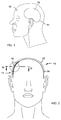
- thermoelectric is based on the Seebeck effect Energy converter 10 in the mastoid area 11 of the head 12 of a patient is tight implanted under the skin, i.e. between scalp 13 and skull cap 14.
- the heat pole 15 is in the illustrated embodiment with the sine Sigmoideus 17 (Fig. 4) of The implant carrier is kept in heat coupling during the cold pole 16 of the energy converter with the sigmoid sinus adjacent to the body surface Mastaid region 11 is kept in heat coupling.
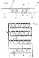
- the energy converter 10 is provided with a plurality n of Seebeck elements or individual modules 20 which are electrically coupled to one another.
- Each individual module has two legs 21, 22 made of differently electrically conductive materials, one end of which is connected in a heat-conducting manner to the cold pole 16 and the other end to the heat pole 15 of the energy converter 10.
- the individual modules 20 are mechanically connected to one another by a thermally insulating composite element 23 made of biocompatible material and arranged between the cold pole 16 and the heat pole 15.
- the thermally insulating composite element 23 is shown as a separating layer between the heat and cold pole.
- the thermally insulating composite element 23 is in the form of potting material which fills the gaps remaining between the individual modules 20, the cold pole 16 and the heat pole 15.
- the electrical connection poles are designated by 24.
- the energy converter 10 has a plurality of Module groups 25 from individual modules 20 electrically connected in series with one another These module groups 25 are in turn electrically connected in parallel with one another.
- an energy storage device 27 which is constructed in particular from long-life capacitors and equipped with a known electronic energy management system can be.
- an implantable electrochemical secondary element can also be used 32 (accumulator) may be provided directly by the energy converter 10 or is charged via the energy store 27 if the device 26 does not need it electrical energy from the energy converter 10 is available, and if necessary emits electrical energy to the device 26.
- an implantable control unit 28 is additionally provided is provided, the task of which is the intermediate storage of the energy converter 10 generated electrical energy in the implanted memory array 27 and / or the forwarding of energy to the device 26 via an electrical connection 29 regulate.
- the control unit 28 can in turn use an external control and / or programming arrangement 31 via a transcutaneous data link 30 from outside the body of the implant carrier are controlled and / or programmed.
- the energy converter 10 the storage arrangement 27 and the control unit 28 combined into a first implant 33, while the device 26 a second Implant 34 forms that with the first implant 33 via the electrical connection 29 is connected.
- FIG. 9 shows an exemplary embodiment in which the energy converter 10, the storage arrangement 27, the control unit 28 and the device 26 in a single implant 35 are integrated and in which by means of the control unit 28 not only the memory arrangement 27, but also the device 26 is controlled and / or programmed. It is the device 26, for example a stimulus generator, its output 36 can be connected to a corresponding stimulus electrode.
Abstract
Gegenstand der Erfindung sind ein Verfahren und eine Vorrichtung zur Versorgung eines mindestens teilimplantierten aktiven Gerätes mit elektrischer Energie, die von einem implantierten, auf dem Seebeck - Effekt basierenden thermoelektrischen Energiewandler erzeugt wird. Dabei wird der Wärmepol des Energiewandlers in einem Bereich der Körperoberfläche, vorzugsweise im Schädel- oder Halsbereich, des Implantatträgers so positioniert, daß er mindestens näherungsweise auf Körperkerntemperatur gehalten wird, während der Kältepol (16) des Energiewandlers mit einem möglichst nahe der Körperoberfläche in Außenhautnähe liegenden Bereich, vorzugsweise im Schädel- oder Haisbereich (11), des Implantatträgers in Wärmekopplung gehalten wird. Der Energiewandler (10) weist eine Mehrzahl von miteinander elektrisch gekoppelten Einzelmodulen (20) auf. <IMAGE>The invention relates to a method and a device for supplying an at least partially implanted active device with electrical energy which is generated by an implanted thermoelectric energy converter based on the Seebeck effect. The heat pole of the energy converter is positioned in an area of the body surface, preferably in the skull or neck area, of the implant carrier in such a way that it is kept at least approximately at the core body temperature, while the cold pole (16) of the energy converter lies with the skin surface as close as possible to the outer skin Area, preferably in the skull or shark area (11), of the implant carrier is kept in heat coupling. The energy converter (10) has a plurality of individual modules (20) which are electrically coupled to one another. <IMAGE>
Description
Die Erfindung betrifft ein Verfahren und eine Vorrichtung zur Versorgung eines mindestens teilimplantierten aktiven Gerätes, insbesondere einer Hörhilfe, mit elektrischer Energie, die von einem implantierten, auf dem Seebeck - Effekt basierenden thermoelektrischen Energiewandler erzeugt wird.The invention relates to a method and a device for supplying at least one partially implanted active device, in particular a hearing aid, with electrical energy, that of an implanted thermoelectric based on the Seebeck effect Energy converter is generated.
Ein solches Verfahren und eine entsprechende Vorrichtung wurden allgemein schon von H.-J. Wanjura in dem Aufsatz "Zur künftigen Energieversorgung von Herzschrittmachern" in Medizinal-Markt/Acta Medicotechnica, 1969, Nr. 3, S. 98-100 vorgeschlagen. Eine konkrete Ausführung ist aus DE 195 30 382 A1 bekannt. Dabei wird der menschliche Körper als Wärmequelle für einen Energiewandler genutzt, der in dem dort als bevorzugt offenbarten Ausführungsbeispiel aus einem Zinkdraht und einem Kupferdraht besteht. Die Verbindungsstelle der beiden Drähte wird der Wärmequelle ausgesetzt, bei der es sich vorzugsweise um die menschliche Haut handelt. Eine unregelmäßige Spannungserzeugung durch den Energiewandler wird von einem Kondensator abgepuffert. Die bereitgestellte Spannung kann einem Mikroprozessor zugeführt werden, der für eine konstante Gleichspannung sorgt.Such a method and a corresponding device have generally been developed by H.-J. Wanjura in the essay "For the future energy supply of pacemakers" in Medizinal-Markt / Acta Medicotechnica, 1969, No. 3, pp. 98-100. A concrete implementation is known from DE 195 30 382 A1. The human Body used as a heat source for an energy converter, which is preferred there disclosed embodiment consists of a zinc wire and a copper wire. The The junction of the two wires is exposed to the heat source, which is preferred is about human skin. An irregular voltage generation the energy converter buffers a capacitor. The provided Voltage can be supplied to a microprocessor, which ensures a constant DC voltage worries.
Die Nutzung des Seebeck-Effektes zur Bereitstellung der zum Betrieb von mindestens teilweise implantierbaren aktiven Systemen benötigten elektrischen Energie hat bislang keinen Eingang in die medizinische Praxis gefunden. Dies dürfte darauf zurückzuführen sein, daß die mit den bekannten Vorrichtungen erzielbaren Energiewerte unzureichend sind, unter anderem weil die an dem thermoelektrischen Energiewandler verfügbaren Temperaturdifferenzen jedenfalls dann sehr klein sind, wenn der Energiewandler implantiert wird. The use of the Seebeck effect to provide for the operation of at least electrical energy required by partially implantable active systems has so far no entry into medical practice found. This should be due to this be that the energy values achievable with the known devices are inadequate are, among other things, because those available on the thermoelectric energy converter Temperature differences are in any case very small when the energy converter implants becomes.
Der Erfindung liegt die Aufgabe zugrunde, ein in der medizinischen Praxis brauchbares Verfahren und eine entsprechende Vorrichtung zur Versorgung eines teil- oder vollimplantierten aktiven Gerätes, insbesondere einer Hörhilfe, mit elektrischer Energie zu schaffen, wobei die Energie von einem implantierten, auf dem Seebeck - Effekt basierenden thermoelektrischen Energiewandler erzeugt wird.The invention has for its object a useful in medical practice Method and a corresponding device for supplying a partially or fully implanted to create active devices, in particular a hearing aid, with electrical energy, the energy from an implanted, based on the Seebeck effect thermoelectric energy converter is generated.
Ausgehend von einem Verfahren der eingangs genannten Art wird diese Aufgabe erfindungsgemäß dadurch gelöst, daß der Wärmepol des Energiewandlers in einem Bereich der Körperoberfläche, vorzugsweise im Schädel- oder Halsbereich, des Implantatträgers so positioniert wird, daß er, bevorzugt durch Wärmekopplung mit einer der großen Venen oder Arterien, mindestens näherungsweise auf Körperkerntemperatur gehalten wird, und daß der Kältepol des Energiewandlers mit einem möglichst nahe der Körperoberfläche in Außenhautnähe liegenden Bereich, vorzugsweise einem möglichst nahe der Körperoberfläche liegenden Schädel- oder Halsbereich, des Implantatträgers in Wärmekopplung gehalten wird.Starting from a method of the type mentioned at the outset, this object is achieved according to the invention solved in that the heat pole of the energy converter in a range of Body surface, preferably in the skull or neck area of the implant wearer positioned that it is, preferably by heat coupling with one of the large veins or arteries, at least approximately maintained at core body temperature, and that the cold pole of the energy converter with as close as possible to the body surface in Area close to the skin, preferably as close as possible to the body surface lying skull or neck area, the implant carrier in heat coupling is held.
Eine Vorrichtung zur Versorgung eines mindestens teilimplantierten aktiven Gerätes, insbesondere einer Hörhilfe, mit elektrischer Energie, mit einem implantierbaren, auf dem Seebeck - Effekt basierenden thermoelektrischen Energiewandler, der vom Körper des Implantatträgers bereitgestellte thermische Energie nutzt, ist erfindungsgemäß dadurch gekennzeichnet, daß der Energiewandler eine Mehrzahl von miteinander elektrisch gekoppelten Einzelmodulen aufweist, daß der Wärmepol des Energiewandlers zur Wärmekopplung mit einem mindestens näherungsweise auf Körperkerntemperatur gehaltenen Implantationsort im Bereich der Körperoberfläche, insbesondere im Schädel- oder Halsbereich, vorzugsweise einer der großen Venen oder Arterien, des Implantatträgers ausgebildet ist und daß der Kältepol des Energiewandlers zur Wärmekopplung mit einem möglichst nahe der Körperoberfläche in Außenhautnähe liegenden Bereich, vorzugsweise einem möglichst nahe der Körperoberfläche liegenden Schädel- oder Halsbereich, des Implantatträgers ausgebildet ist.A device for supplying an at least partially implanted active device, in particular a hearing aid, with electrical energy, with an implantable, on the Seebeck effect based thermoelectric energy converter which is generated by the body of the According to the invention, the implant carrier uses the thermal energy provided characterized in that the energy converter has a plurality of electrically coupled to each other Has individual modules that the heat pole of the energy converter for heat coupling with an implantation site kept at least approximately at body core temperature in the area of the body surface, especially in the skull or neck area, preferably one of the large veins or arteries, the implant carrier is formed and that the cold pole of the energy converter for heat coupling with one as close as possible the area of the body near the outer skin, preferably an area where possible Skull or neck area of the implant carrier located near the body surface is.
Bei dem Verfahren und der Vorrichtung nach der Erfindung wird die ständig zur Verfügung stehende thermische Energie des Körpers direkt in elektrische Energie umgewandelt. In the method and the device according to the invention that is always available standing thermal energy of the body is converted directly into electrical energy.
Dies geschieht dadurch, daß die konstruktionsbedingte und durch den Implantationsort gegebene Temperaturdifferenz zwischen Körperkerntemperatur und Körperoberflächentemperatur genutzt wird. Diese Temperaturdifferenz als thermodynamische Energieform wird durch den physikalischen Seebeck-Effekt direkt in elektrische Energie umgewandelt. Der Seebeck-Effekt ist die Umkehrform des bekannten Peltier-Effektes, bei dem durch Zufuhr von elektrischer Energie in eine geeignete Werkstoffpaarung eine Temperaturdifferenz an örtlich verschiedenen Zonen des Elementes erzeugt wird. Der Seebeck-Effekt wird erreicht z.B. durch die konstruktive Paarung von Metallen, die in der thermoelektrischen Spannungsreihe einen möglichst weiten Abstand aufweisen. Eine noch wirkungsvollere Ausnutzung des Effektes wird durch die konstruktive Verbindung von speziell dotierten Halbleitermaterialien erzielt.This happens because of the design-related and by the implantation site given temperature difference between body core temperature and body surface temperature is being used. This temperature difference as a thermodynamic form of energy is converted directly into electrical energy by the physical Seebeck effect. The Seebeck effect is the reverse of the well-known Peltier effect, in which Supply of electrical energy in a suitable material pairing a temperature difference is generated at different zones of the element. The Seebeck effect is reaches e.g. through the constructive pairing of metals used in thermoelectric Have the voltage series as far apart as possible. An even more effective one Exploitation of the effect is achieved through the constructive combination of specially doped Semiconductor materials achieved.
Der Schädel- oder Haisbereich des Implantatträgers ist nur selten oder nie von wärmeisolierender Kleidung bedeckt. Er hat daher normalerweise eine Temperatur, die unter der Körperkerntemperatur liegt. Andererseits sind die in diesem Bereich befindlichen großen Venen oder Arterien, zum Beispiel die Vena jugularis externa, die Vena jugularis anterior, der Sinus transversus oder die Arteria carotis externa, blutdurchströmte Gefäße, welche einen kontinuierlichen Wärmeenergielieferant mit kleinem thermischen Innenwiderstand darstellen, der auch bei andauerndem Wärmeentzug durch das Wandlerelement permanent ausreichend thermische Körperenergie nachliefern kann. Die erfindungsgemäße Art der Wärmeankopplung für den Kältepol und den Wärmepol stellt daher eine für den praktischen Einsatz ausreichende Temperaturdifferenz sicher. Es kann dabei von einem im zeitlichen Mittel konstanten ΔT ausgegangen werden, so daß sich durch das Seebeck-Element zeitlich unbegrenzt, langzeitstabil und verschleißfrei direkt elektrische Energie gewinnen läßt. Wesentliche Vorteile gegenüber bisher verwendeten implantierbaren Energieversorgungssystemen, wie primäre oder sekundäre elektrochemische Elemente (DE 4 104 359 C, US-PS 4 134 408, EP 0 341 902 A), Biobrennstoffzellen (DE-OS 2 200 054 und DE-OS 2 415 385), Nuklearbatterien (EP 0 761 256 A) und Vorrichtungen zur direkten Wandlung von mechanischer Bewegungsenergie (z. B. des Herzmuskels) in elektrische Energie mittels mechanoelektrischer Wandlerprinzipien [Piezoeffekt (DE-OS 2 729 223), mechanische Unruhe-Systeme und dergleichen(DE 1 764 622 C, DE 2 020 380 C], bestehen darin, daß
- das Seebeck-Element nicht selbstverbrauchend arbeitet, d.h., es werden keine Stoffe umgesetzt;
- das Seebeck-Element keinerlei mechanisch bewegten Teile aufweist und daher keinem mechanischen Verschleiß unterliegt;
- die Lebensdauer aus den vorstehend genannten Gründen prinzipiell unbegrenzt ist;
- der Implantatträger sich nicht bewußt um die energetische Versorgung seines Implantates
bemühen muß, d h das Implantatsystem geht für lange Zeit in einen unterbewußten Zustand" ein;

- die Energiezufuhr durch die körperintern geregelte Temperatur eingangsseitig weitgehend konstant ist.
- the Seebeck element does not work self-consuming, ie no substances are used;
- the Seebeck element has no mechanically moving parts and is therefore not subject to mechanical wear;
- the service life is in principle unlimited for the reasons mentioned above;
- the implant carrier does not have to consciously strive to supply his implant with energy, ie the implant system goes into one for a long time subconscious state "a;
- the supply of energy is largely constant on the input side due to the temperature regulated inside the body.
Grundlegende eigene Laborversuche mit handelsüblichen Seebeck-Elementen haben gezeigt:
- Bei einer angenommenen Temperaturdifferenz von 0,5 K, einer Querschnittsfläche von ca. 0,25 mm2 und einem Volumen eines Elementes unter 1 mm3 ist eine elektrische Ausgangsleistung von rund 0,5 µ Watt erreichbar.
- Bei nur zehn dieser Elemente ergibt sich eine elektrische Dauerleistung von etwa 5 µWatt. Diese Leistung ist bereits ausreichend, um die Stand-By-Leistungsaufnahme eines modernen Herzschrittmachers oder Neurostimulators zu decken, solange kein neurostimulierender Reizimpuls abgesetzt wird.
- Durch geeignete Anordnung von einer großen Zahl (im Bereich über 100.000) miniaturisierter Seebeck-Elemente durch z.B. mikrosystemtechnische oder halbleiter-lithografische Verfahren kann bei geeigneter Verschaltung der Einzelelemente ein Gesamtsystem realisiert werden, das bei einer abschätzbaren Modulfläche im Bereich von 100 bis 300 cm2 und einer Temperaturdifferenz von 0,5 K kontinuierlich elektrische Leistungen im Bereich von 1 bis 3 mWatt bei einer Klemmenspannung von 1 bis 2 Volt abgeben kann. Die elektrische Quellimpedanz (Innenwiderstand) liegt dabei in einem Bereich von 100 bis 300 Ω, so daß ein kontinuierlich arbeitendes Implantat, wie insbesondere Hörhilfen, energetisch versorgbar ist.
- With an assumed temperature difference of 0.5 K, a cross-sectional area of approximately 0.25 mm 2 and a volume of an element less than 1 mm 3 , an electrical output power of approximately 0.5 μ watts can be achieved.
- With only ten of these elements, a continuous electrical output of about 5 µWatt results. This power is already sufficient to cover the stand-by power consumption of a modern pacemaker or neurostimulator, as long as no neurostimulating stimulation pulse is released.
- Through a suitable arrangement of a large number (in the area of over 100,000) of miniaturized Seebeck elements by means of, for example, microsystem technology or semiconductor-lithographic processes, an overall system can be realized with suitable interconnection of the individual elements, with an assessable module area in the range from 100 to 300 cm 2 and a temperature difference of 0.5 K can continuously deliver electrical power in the range of 1 to 3 mWatt at a terminal voltage of 1 to 2 volts. The electrical source impedance (internal resistance) is in a range from 100 to 300 Ω, so that a continuously operating implant, such as hearing aids in particular, can be supplied with energy.
In bevorzugter weiterer Ausgestaltung der Erfindung wird der Wärmepol des Energiewandlers mit dem Sinus Sigmoideus des Implantatträgers in Wärmekopplung gehalten wird, während der Kältepol des Energiewandlers mit der benachbart dem Sinus Sigmoideus nahe der Körperoberfläche liegenden Mastoidregion des Implantatträgers hinter dem Außenohr in Wärmekopplung gehalten wird. Dort steht Knochenstruktur in ausreichendem Maße nahe unter der Hautoberfläche zur Verfügung, und die den Sinus Sigmoideus bedeckende knöcherne Struktur ist nach einer operationstechnischen Standardprozedur (Mastoidektomie) relativ einfach zugänglich. Es ist eine weitgehend konstante Nachlieferung von Wärmeenergie an den Wärmepol gewährleistet.In a preferred further embodiment of the invention, the heat pole of the energy converter kept in heat coupling with the sine sigmoid of the implant carrier becomes, while the cold pole of the energy converter with the neighboring sine sigmoideus Mastoid region of the implant carrier located near the body surface behind the Outer ear is kept in heat coupling. There is sufficient bone structure there Measurements available close under the skin surface, and those covering the sigmoid sinus bony structure is following a standard surgical procedure (mastoidectomy) relatively easy to access. It is a largely constant subsequent delivery of Guaranteed thermal energy to the heat pole.
Von dem Energiewandler erzeugte elektrische Energie kann in einer implantierbaren Speicheranordnung
gesammelt und zwischengespeichert werden, bis sie von dem mindestens
teilimplantierten aktiven Gerät benötigt wird. Ein typisches Anwendungsbeispiel sind
Die Zwischenspeicherung der von dem Energiewandler erzeugten elektrische Energie in der implantierbaren Speicheranordnung und/oder die Energieweiterleitung an den Verbraucher können zweckmäßig über eine implantierbare Steuereinheit, wie einen Mikroprozessor oder Mikrokontroller, geregelt werden, der entsprechende Peripherie-Hardware (AD- und DA-Wandler, Stromstellglieder und dergleichen) zugeordnet ist und die ihrerseits nur sehr wenig elektrische Betriebsieistung erfordert, da in der Regel keine zeitlich schnellen Vorgänge bearbeitet werden müssen.The intermediate storage of the electrical energy generated by the energy converter in the implantable storage arrangement and / or the forwarding of energy to the consumer can be conveniently via an implantable control unit, such as a microprocessor or microcontroller, are regulated, the corresponding peripheral hardware (AD and DA converters, current actuators and the like) is assigned and which in turn requires very little electrical operating power, as a rule no time fast processes must be processed.
Die implantierbare Steuereinheit kann insbesondere über eine Datenschnittstelle drahtlos.
transkutan von außerhalb des Körpers des Implantatträgers über eine entsprechende
externe Steueranordnung programmierbar sein, um das Gesamtsystem
Der Energiewandler weist bevorzugt eine Vielzahl von miteinander elektrisch gekoppelten Einzelmodulen auf, wobei jedes Einzelmodul mit zwei Schenkeln aus unterschiedlich elektrisch leitenden Werkstoffen versehen ist, deren eines Ende mit dem Kältepol und deren anderes Ende mit dem Wärmepol des Energiewandlers wärmeleitend verbunden ist. Der Aufbau des Energiewandlers und dessen Herstellungsverfahren können von an sich bekannten Merkmalen Gebrauch machen, wie sie unteren anderem aus US-PS 4 095 998, US-PS 5 439 528, US-PS 5 430 322, JP 09 092 889 A, EP 0 731 513, WO 94/16464, WO 96/15412 und WO 97/44993 bekannt sind.The energy converter preferably has a plurality of electrically coupled ones Individual modules on, each individual module with two legs from different electrically conductive materials is provided, one end of which with the cold pole and the other end of which is thermally conductively connected to the heat pole of the energy converter. The structure of the energy converter and its manufacturing process can in itself make use of known features, such as, inter alia, from US Pat. No. 4,095,998, US Pat. No. 5,439,528, US Pat. No. 5,430,322, JP 09 092 889 A, EP 0 731 513, WO 94/16464, WO 96/15412 and WO 97/44993 are known.
Die Schenkel der Einzelmodule können insbesondere aus Halbleiterwerkstoffen mit n-beziehungsweise p-Dotierung oder aus unterschiedlichen Metallen mit großem Abstand in der thermoelektrischen Spannungsreihe bestehen. Als Materialkombinationen für das bzw. die Seebeck-Elemente kommen unter anderem Germanium-Silizium-Mischkristalle und Wismut-Tellur-Kombinationen als Halbleiterelemente mit geeignet gewählter Dotierung in Frage. Weitere grundsätzlich geeignete Werkstoffkombinationen sind unter anderem in WO 94/14200, EP 0 712 537 A sowie in US-PS 5 747 728 und US-PS 5 356 485 sowie den dort aufgelisteten Literaturstellen beschrieben.The legs of the individual modules can in particular be made of semiconductor materials with n or p-doping or from different metals with a large distance in the thermoelectric voltage series exist. As material combinations for the or the Seebeck elements include germanium-silicon mixed crystals and Bismuth-tellurium combinations as semiconductor elements with a suitably chosen doping in Question. Other fundamentally suitable combinations of materials are included in WO 94/14200, EP 0 712 537 A and in US Pat. No. 5,747,728 and US Pat. No. 5,356,485 and the literature references listed there.
Der Kältepol und der Wärmepol sind vorteilhaft aus biokompatiblem, gut wärmeleitendem Werkstoff gefertigt. Dabei kommen insbesondere reines Titan, Titanlegierungen, Niob, Nioblegierungen, Tantal, Tantallegierungen, Edelstähle und keramische Werkstoffe wie Aluminiumoxid-Keramik in Betracht.The cold pole and the heat pole are advantageously made of biocompatible, good heat-conducting Made of material. Pure titanium, titanium alloys, niobium, Niobium alloys, tantalum, tantalum alloys, stainless steels and ceramic materials such as Alumina ceramic into consideration.
Die Einzelmodule sind zweckmäßig durch einen zwischen dem Kältepol und dem Wärmepol angeordneten biokompatiblen thermischen Isolator mechanisch miteinander verbunden, wobei der Werkstoff des thermisch isolierenden Verbundelements vorzugsweise aus der aus Polytetrafluorethylen, Polycarbonaten, Polyurethan, Silikonen und kohlefaserverstärkten Polymeren bestehenden Gruppe ausgewählt ist. The individual modules are expedient by a between the cold pole and the heat pole arranged biocompatible thermal insulator mechanically connected to each other, wherein the material of the thermally insulating composite element is preferably made of Made of polytetrafluoroethylene, polycarbonates, polyurethane, silicones and carbon fiber reinforced Polymer existing group is selected.
Das thermisch isolierende Verbundelement kann in herstellungstechnisch besonders einfacher Weise die zwischen den Einzelmodulen, dem Kältepol und dem Wärmepol verbleibenden Zwischenräume in Form von Vergußmaterial ausfüllen. Die sonst bei aktiven, Mikroelektronik enthaltenden Implantaten zu fordernde hermetische Gasdichtigkeit ist bei dem vorliegendem Anwendungsfall nicht zwingend notwendig, insbesondere dann, wenn geringe Volumenanteile Wasserdampf das Seebeck-Modul intern langzeitgemäß nicht schädigen und andererseits keine toxischen Stoffe in den Körper austreten können. Das Vergußmaterial kann daher auch gut körperverträgliches Silikon sein.The thermally insulating composite element can be particularly simple in terms of production technology Way the remaining between the individual modules, the cold pole and the heat pole Fill in the spaces in the form of potting material. The otherwise with active, Implants containing microelectronics require hermetic gas-tightness the present application is not absolutely necessary, especially if the Seebeck module does not have a low volume of water vapor for a long time damage and on the other hand no toxic substances can escape into the body. The Potting material can therefore also be silicone that is well tolerated by the body.
In weiterer Ausgestaltung der Erfindung weist der Energiewandler eine Mehrzahl von Modulgruppen aus miteinander elektrisch in Reihe geschalteten Einzelmodulen auf, wobei diese Modulgruppen ihrerseits elektrisch parallel geschaltet sind. Durch geeignete Anordnung einer großen Zahl (im Bereich über 100.000) von miniaturisierten Seebeck-Elementen durch z.B. mikrosystemtechnische oder halbleiter-lithografische Verfahren kann durch entsprechende elektrische Serien-Parallel-Schaltung und Zusammenfassung der Einzelelemente zu Modulgruppen ein Gesamtsystem realisiert werden, das bei einer abschätzbaren Modulfläche im Bereich von 100 bis 300 cm2 und einer Temperaturdifferenz von 0,5 K kontinuierlich elektrische Leistungen im Bereich von 1 bis 3 mWatt bei einer Klemmenspannung von 1 bis 2 Volt abgeben kann. Die elektrische Quellimpedanz (Innenwiderstand) kann dabei in einem Bereich von 100 bis 300 Ω liegen, so daß ein kontinuierlich arbeitendes, sensorisches Implantat, wie insbesondere Hörhilfen, energetisch versorgbar ist.In a further embodiment of the invention, the energy converter has a plurality of module groups of individual modules electrically connected in series with one another, these module groups in turn being electrically connected in parallel. By suitably arranging a large number (in the area of over 100,000) of miniaturized Seebeck elements, for example by means of microsystem technology or semiconductor lithographic processes, an overall system can be implemented by means of appropriate electrical series-parallel connection and combining the individual elements into module groups, with an assessable module area in the range of 100 to 300 cm 2 and a temperature difference of 0.5 K can continuously deliver electrical power in the range of 1 to 3 mWatts at a terminal voltage of 1 to 2 volts. The electrical source impedance (internal resistance) can be in a range from 100 to 300 Ω, so that a continuously working, sensory implant, such as hearing aids in particular, can be supplied with energy.
Der Kältepol kann vorteilhaft entweder selbst einen unmittelbar unter der Haut des Implantatträgers positionierbaren großflächigen Kühlkörper bilden oder mit einem solchen Kühlkörper wärmeleitend gekoppelt sein, was zu einer erhöhten Temperaturdifferenz führt.The cold pole can be advantageous either directly under the skin of the Form implantable positionable large-area heat sink or with such Heatsink be coupled thermally, which leads to an increased temperature difference.
Der Energiewandler kann grundsätzlich jede geometrische Form annehmen. Vor allem bei relativ kleinen Modulen kann er eben und flächig aufgebaut sein. Bei größeren Modulen ist insbesondere in der bevorzugten Kopfregion und dem Mastoidbereich ein gewölbtes Element vorzuziehen, das zweckmäßig nur einige mm dick ist und einem Kalottenabschnitt entspricht, der möglichst optimal der gewölbten Kopfoberfläche angepaßt ist. The energy converter can basically take any geometric shape. Especially with relatively small modules, it can be flat and flat. For larger modules a curved element, particularly in the preferred head region and the mastoid region preferable, which is conveniently only a few mm thick and a calotte section corresponds, which is optimally adapted to the curved head surface.
Der vorliegend beschriebene thermoelektrische Energiewandler kann mit dem vorgesehenen aktiven Implantat eine Einheit bilden und dadurch ein implantationsfertiges Gesamtmodul darstellen. Hier sind insbesondere aktive, elektronische Hörimplantate zu nennen, die mit direkter elektrischer Reizung das Innenohr stimulieren (vollständig implantierbares Cochlea Implantat) (siehe zum Beispiel EP 0 076 070 und EP 0 124 930), oder mit mechanischer Stimulation des Mittel- oder Innenohres eine Teitschädigung des Innenohres rehabilitieren (Innenohrschwerhörigkeiten). Systeme der letztgenannten Art sind u.a. bekannt aus EP 0 400 630 B und EP 0 499 940 B. Der thermoelektrische Energiewandler kann auch als eigenständiges Implantat ausgeführt sein, von dessen elektrischem Ausgang, z.B. über eine geeignete, zweipolige Steckverbindung und eine adäquate elektrische Zuleitung, die elektrische Energie dem Verbraucherimplantat zugeführt wird, das nicht zwingend am gleichen Implantationsort positioniert sein muß (typisches Beispiel: thermoelektrischer Energiewandler im Mastoid, elektrische Zuleitung durch Hals, Verbraucher ist Herzschrittmacher oder sonstiger Neurostimulator im Brustraum oder Abdominalbereich).The thermoelectric energy converter described here can be used with the provided one active implant form a unit and thereby an implant-ready overall module represent. Active electronic hearing implants are particularly worth mentioning here, which stimulate the inner ear with direct electrical stimulation (completely implantable Cochlear implant) (see for example EP 0 076 070 and EP 0 124 930), or with mechanical Stimulation of the middle or inner ear rehabilitates damage to the inner ear (Inner ear deafness). Systems of the latter type include known from EP 0 400 630 B and EP 0 499 940 B. The thermoelectric energy converter can also be designed as a separate implant, from its electrical output, e.g. about a suitable, two-pin connector and an adequate electrical lead, the electrical energy is supplied to the consumer implant, which is not mandatory on same implantation location must be positioned (typical example: thermoelectric Energy converter in the mastoid, electrical supply through the neck, consumer is a pacemaker or other neurostimulator in the chest or abdominal area).
Die Erfindung ist nachstehend unter Bezugnahme auf die beiliegenden Zeichnungen näher erläutert. Dabei zeigen:
- Fig. 1
- schematisch eine Seitenansicht des Kopfes eines Patienten mit dicht unter der Haut im Mastoidbereich implantiertem, auf dem Seebeck - Effekt basierendem thermoelektrischem Energiewandler,
- Fig. 2
- eine Frontansicht der Anordnung nach Fig. 1, teilweise in Schnittdarstellung,
- Fig 3
- in größerem Maßstab einen Teilausschnitt der Anordnung nach Fig. 2,
- Fig. 4
- in größerem Maßstab einen Teilquerschnitt entlang der Linie IV-IV in Fig.2,
- Fig. 5
- in noch größerem Maßstab eine schematische Schnittansicht eines erfindungsgemäßen Energiewandlers
- Fig. 6
- eine schematische Teilansicht eines erfindungsgemäßen Energiewandlers, welche eine Serien/Parallel - Schaltung von mehreren Seebeck - Einzelmodulen erkennen läßt,
- Fig. 7
- ein Blockschaltbild für eine erste Anwendung des erfindungsgemäßen Energiewandlers,
- Fig. 8
- ein Blockschaltbild für eine zweite Anwendung des erfindungsgemäßen Energiewandlers,und
- Fig. 9
- ein Blockschaltbild für eine dritte Anwendung des erfindungsgemäßen Energiewandlers.
- Fig. 1
- schematically a side view of the head of a patient with a thermoelectric energy converter based on the Seebeck effect implanted just under the skin in the mastoid area,
- Fig. 2
- 2 shows a front view of the arrangement according to FIG. 1, partly in a sectional view,
- Fig 3
- on a larger scale, a partial section of the arrangement according to FIG. 2,
- Fig. 4
- on a larger scale, a partial cross section along the line IV-IV in Figure 2,
- Fig. 5
- on an even larger scale, a schematic sectional view of an energy converter according to the invention
- Fig. 6
- 2 shows a schematic partial view of an energy converter according to the invention, which reveals a series / parallel connection of several Seebeck individual modules,
- Fig. 7
- 2 shows a block diagram for a first application of the energy converter according to the invention,
- Fig. 8
- a block diagram for a second application of the energy converter according to the invention, and
- Fig. 9
- a block diagram for a third application of the energy converter according to the invention.
Entsprechend den Figuren 1 bis 4 ist ein auf dem Seebeck - Effekt basierender thermoelektrischer
Energiewandler 10 im Mastoidbereich 11 des Kopfes 12 eines Patienten dicht
unter der Haut, das heißt zwischen Kopfhaut 13 und Schädelkalotte 14, implantiert. Der
Energiewandler 10 weist einen Wärmepol 15 und einen Kältepol 16 auf. Der Wärmepol 15
wird im veranschaulichten Ausführungsbeispiel mit dem Sinus Sigmoideus 17 (Fig. 4) des
Implantatträgers in Wärmekopplung gehalten während der Kältepol 16 des Energiewandlers
mit der benachbart dem Sinus Sigmoideus nahe der Körperoberfläche liegenden
Mastaidregion 11 in Wärmekopplung gehalten wird.According to FIGS. 1 to 4, a thermoelectric is based on the Seebeck
Gemäß den Figuren 3, 5 und 6 ist der Energiewandler 10 mit einer Mehrzahl n von miteinander
elektrisch gekoppelten Seebeck - Elementen oder Einzelmodulen 20 versehen. Jedes
Einzelmodul weist zwei Schenkel 21, 22 aus unterschiedlich elektrisch leitenden Werkstoffen
auf, deren eines Ende mit dem Kältepol 16 und deren anderes Ende mit dem Wärmepol
15 des Energiewandlers 10 wärmeleitend verbunden ist. Die Einzelmodule 20 sind durch
ein zwischen dem Kältepol 16 und dem Wärmepol 15 angeordnetes, thermisch isolierendes
Verbundelement 23 aus biokompatiblem Werkstoff mechanisch miteinander verbunden. In
Fig. 3 ist das thermisch isolierende Verbundelement 23 als Trennschicht zwischen Wärme- und
Kältepol dargestellt. Bei der Ausführungsform gemäß Fig. 5 liegt das thermisch isolierende
Verbundelement 23 in Form von Vergußmaterial vor, das die zwischen den Einzelmodulen
20, dem Kältepol 16 und dem Wärmepol 15 verbleibenden Zwischenräume ausfüllt.
Die elektrischen Anschlußpole sind mit 24 bezeichnet. According to FIGS. 3, 5 and 6, the
Bei der Ausführungsform gemäß Fig. 6 weist der Energiewandler 10 eine Mehrzahl von
Modulgruppen 25 aus miteinander elektrisch in Reihe geschalteten Einzelmodulen 20 auf
Diese Modulgruppen 25 sind ihrerseits untereinander elektrisch parallel geschaltet.In the embodiment according to FIG. 6, the
Entsprechend Fig. 7 ist zwischen den Energiewandler 10 und ein von diesem mit elektrischer
Energie versorgtes teil- oder vollimplantiertes aktives Gerät (aktives Implantat) 26
ein Energiespeicher 27 geschaltet, der insbesondere aus langlebigen Kondensatoren aufgebaut
und mit einem an sich bekannten elektronischen Energie - Managementsystem ausgestattet
sein kann. Fakultativ kann auch ein implantierbares elektrochemisches Sekundärelement
32 (Akkumulator) vorgesehen sein, das von dem Energiewandler 10 unmittelbar
oder über den Energiespeicher 27 aufgeladen wird, wenn von dem Gerät 26 nicht benötigte
elektrische Energie von dem Energiewandler 10 zur Verfügung steht, und das im Bedarfsfall
elektrische Energie an das Gerät 26 abgibt.7 is between the
Fig. 8 zeigt eine Ausführungsform, bei der zusätzlich eine implantierbare Steuereinheit 28
vorgesehen ist, deren Aufgabe darin besteht, die Zwischenspeicherung der von dem Energiewandler
10 erzeugten elektrische Energie in der implantierten Speicheranordnung 27
und/oder die Energieweiterleitung an das Gerät 26 über eine elektrische Verbindung 29 zu
regeln. Die Steuereinheit 28 kann ihrerseits mittels einer externen Steuer- und/oder Programmieranordnung
31 über eine transkutane Datenstrecke 30 von außerhalb des Körpers
des Implantatträgers gesteuert und/oder programmiert werden. Bei dem Ausführungsbeispiel
gemäß Fig. 8 sind der Energiewandler 10, die Speicheranordnung 27 und die Steuereinheit
28 zu einem ersten Implantat 33 zusammengefaßt, während das Gerät 26 ein zweites
Implantat 34 bildet, das mit dem ersten Implantat 33 über die elektrische Verbindung
29 verbunden ist.8 shows an embodiment in which an
Fig. 9 zeigt dagegen ein Ausführungsbeispiel, bei dem der Energiewandler 10, die Speicheranordnung
27, die Steuereinheit 28 und das Gerät 26 in einem einzigen Implantat 35
integriert sind und bei dem mittels der Steuereinheit 28 nicht nur die Speicheranordnung
27, sondern auch das Gerät 26 gesteuert und/oder programmiert wird. Handelt es sich bei
dem Gerät 26 beispielsweise um einen Reizgenerator, kann dessen Ausgang 36 mit einer
entsprechenden Reizelektrode verbunden sein.9 shows an exemplary embodiment in which the
Claims (26)
Applications Claiming Priority (2)
| Application Number | Priority Date | Filing Date | Title |
|---|---|---|---|
| DE19827898 | 1998-06-23 | ||
| DE19827898A DE19827898C1 (en) | 1998-06-23 | 1998-06-23 | Electrical energy supply for an implant, eg. a hearing aid |
Publications (3)
| Publication Number | Publication Date |
|---|---|
| EP0967832A2 true EP0967832A2 (en) | 1999-12-29 |
| EP0967832A3 EP0967832A3 (en) | 2006-05-10 |
| EP0967832B1 EP0967832B1 (en) | 2013-07-31 |
Family
ID=7871726
Family Applications (1)
| Application Number | Title | Priority Date | Filing Date |
|---|---|---|---|
| EP99112047.8A Expired - Lifetime EP0967832B1 (en) | 1998-06-23 | 1999-06-22 | Method and device for supplying electric energy to a partially implanted active device |
Country Status (3)
| Country | Link |
|---|---|
| US (1) | US6131581A (en) |
| EP (1) | EP0967832B1 (en) |
| DE (1) | DE19827898C1 (en) |
Families Citing this family (43)
| Publication number | Priority date | Publication date | Assignee | Title |
|---|---|---|---|---|
| DE19915684B4 (en) * | 1999-04-07 | 2005-12-01 | Phonak Ag | Implantable positioning and fixation system for actuator and sensory implants |
| DE10018334C1 (en) * | 2000-04-13 | 2002-02-28 | Implex Hear Tech Ag | At least partially implantable system for the rehabilitation of a hearing impairment |
| DE10018360C2 (en) | 2000-04-13 | 2002-10-10 | Cochlear Ltd | At least partially implantable system for the rehabilitation of a hearing impairment |
| DE10018361C2 (en) | 2000-04-13 | 2002-10-10 | Cochlear Ltd | At least partially implantable cochlear implant system for the rehabilitation of a hearing disorder |
| DE10031832C2 (en) * | 2000-06-30 | 2003-04-30 | Cochlear Ltd | Hearing aid for the rehabilitation of a hearing disorder |
| DE10041726C1 (en) | 2000-08-25 | 2002-05-23 | Implex Ag Hearing Technology I | Implantable hearing system with means for measuring the coupling quality |
| DE10046938A1 (en) | 2000-09-21 | 2002-04-25 | Implex Ag Hearing Technology I | At least partially implantable hearing system with direct mechanical stimulation of a lymphatic space in the inner ear |
| DE10137504A1 (en) * | 2001-07-31 | 2003-02-27 | Enocean Gmbh | Thermally drivable power supply |
| DE10154923A1 (en) * | 2001-11-08 | 2003-06-05 | Klaus Palme | Extracting electrical energy from air temperature fluctuations, involves enclosing heat storage device heated/cooled by ambient air in Peltier/Seebeck element through which heat flows |
| US6640137B2 (en) * | 2002-03-15 | 2003-10-28 | Biomed Solutions Llc | Biothermal power source for implantable devices |
| US7822480B2 (en) * | 2002-06-28 | 2010-10-26 | Boston Scientific Neuromodulation Corporation | Systems and methods for communicating with an implantable stimulator |
| EP1517725B1 (en) | 2002-06-28 | 2015-09-09 | Boston Scientific Neuromodulation Corporation | Microstimulator having self-contained power source and bi-directional telemetry system |
| US20050256549A1 (en) * | 2002-10-09 | 2005-11-17 | Sirius Implantable Systems Ltd. | Micro-generator implant |
| US7596408B2 (en) | 2002-12-09 | 2009-09-29 | Medtronic, Inc. | Implantable medical device with anti-infection agent |
| WO2004052456A1 (en) | 2002-12-09 | 2004-06-24 | Medtronic, Inc. | Modular implantable medical device |
| US7263401B2 (en) | 2003-05-16 | 2007-08-28 | Medtronic, Inc. | Implantable medical device with a nonhermetic battery |
| US7317947B2 (en) * | 2003-05-16 | 2008-01-08 | Medtronic, Inc. | Headset recharger for cranially implantable medical devices |
| US20050004637A1 (en) * | 2003-05-16 | 2005-01-06 | Ruchika Singhal | Explantation of implantable medical device |
| US7596399B2 (en) | 2004-04-29 | 2009-09-29 | Medtronic, Inc | Implantation of implantable medical device |
| US20050245984A1 (en) | 2004-04-30 | 2005-11-03 | Medtronic, Inc. | Implantable medical device with lubricious material |
| WO2006017226A1 (en) * | 2004-07-12 | 2006-02-16 | Cochlear Americas | Thermoelectric power supply |
| JP4330541B2 (en) * | 2005-01-31 | 2009-09-16 | ヤマハ株式会社 | Body temperature utilization power generator and cochlear implant system using the same |
| DE102005032291B3 (en) * | 2005-07-11 | 2006-12-21 | Siemens Audiologische Technik Gmbh | Mobile hearing aid/ear aligner, has thermoelectric transducer with rectangular cross section, where hot and cold poles of transducer contact respective inner and outer sides of cover of sound hose for power supply of aid |
| US7813810B2 (en) * | 2006-01-13 | 2010-10-12 | Cernasov Andre N | Apparatus and method for supplying power to subcutaneously implanted devices |
| US8538529B2 (en) * | 2006-04-26 | 2013-09-17 | Cardiac Pacemakers, Inc. | Power converter for use with implantable thermoelectric generator |
| WO2007127831A2 (en) * | 2006-04-26 | 2007-11-08 | Cardiac Pacemakers, Inc. | Implantable thermoelectric power system |
| US8039727B2 (en) * | 2006-04-26 | 2011-10-18 | Cardiac Pacemakers, Inc. | Method and apparatus for shunt for in vivo thermoelectric power system |
| US8003879B2 (en) | 2006-04-26 | 2011-08-23 | Cardiac Pacemakers, Inc. | Method and apparatus for in vivo thermoelectric power system |
| US9084901B2 (en) | 2006-04-28 | 2015-07-21 | Medtronic, Inc. | Cranial implant |
| JP2008048067A (en) * | 2006-08-11 | 2008-02-28 | Matsushita Electric Works Ltd | Hearing aid |
| EP2124267A3 (en) * | 2008-05-22 | 2012-02-01 | Stichting IMEC Nederland | Thermoelectric generator for implants and embedded devices |
| US8948870B2 (en) | 2008-09-09 | 2015-02-03 | Incube Labs, Llc | Energy harvesting mechanism |
| US9026212B2 (en) | 2008-09-23 | 2015-05-05 | Incube Labs, Llc | Energy harvesting mechanism for medical devices |
| US9393432B2 (en) | 2008-10-31 | 2016-07-19 | Medtronic, Inc. | Non-hermetic direct current interconnect |
| CN102347715A (en) * | 2010-08-02 | 2012-02-08 | 余哲锐 | Hand temperature generating device with effect of displaying temperature difference |
| JP2013542181A (en) * | 2010-09-03 | 2013-11-21 | タフツ ユニバーシティー/トラスティーズ オブ タフツ カレッジ | Plasmon nanoparticle-doped silk material |
| US9084859B2 (en) | 2011-03-14 | 2015-07-21 | Sleepnea Llc | Energy-harvesting respiratory method and device |
| PL2506600T3 (en) * | 2011-04-01 | 2016-12-30 | Power supply for a hearing aid or hearing assistance system | |
| TWI513485B (en) * | 2012-08-15 | 2015-12-21 | Nat Univ Tsing Hua | Implantable device |
| WO2016073944A1 (en) * | 2014-11-06 | 2016-05-12 | The Regents Of The University Of California | Autonomous thermoelectric energy harvesting platform for biomedical sensors |
| US20200254249A1 (en) | 2015-11-17 | 2020-08-13 | Inspire Medical Systems, Inc. | Microstimulation sleep disordered breathing (sdb) therapy device |
| US20190134408A1 (en) * | 2017-11-07 | 2019-05-09 | Qualcomm Incorporated | Cyclic heating and cooling of skin to power thermionic implant |
| FR3081616B1 (en) | 2018-05-24 | 2020-06-12 | Universite Grenoble Alpes | THERMOELECTRIC GENERATOR, IMPLANTABLE DEVICE AND RELATED METHOD |
Citations (8)
| Publication number | Priority date | Publication date | Assignee | Title |
|---|---|---|---|---|
| DE2200054A1 (en) | 1972-01-03 | 1973-07-26 | Siemens Ag | IMPLANTABLE FUEL CELL |
| DE2415385A1 (en) | 1974-03-29 | 1975-10-02 | Siemens Ag | PACEMAKER |
| DE2729223A1 (en) | 1977-06-29 | 1979-01-04 | Eberhard Prof Dr Rer Haeusler | Conversion of physiological mechanical energy into electrical signals - using transducer having high polymer foils with piezoelectric characteristics |
| US4134408A (en) | 1976-11-12 | 1979-01-16 | Research Corporation | Cardiac pacer energy conservation system |
| EP0341902A2 (en) | 1988-05-10 | 1989-11-15 | 3M Hearing Health Aktiebolag | Hearing aid programming interface |
| DE4104359C2 (en) | 1991-02-13 | 1992-11-19 | Implex Gmbh, 7449 Neckartenzlingen, De | |
| DE19530382A1 (en) | 1995-08-18 | 1997-02-20 | Meiners Horst | Generating electrical current, esp. small current |
| EP0761256A2 (en) | 1995-09-01 | 1997-03-12 | Strato/Infusaid Inc. | Power supply for implantable device |
Family Cites Families (21)
| Publication number | Priority date | Publication date | Assignee | Title |
|---|---|---|---|---|
| US2798493A (en) * | 1954-06-09 | 1957-07-09 | Sukacev Lev | Devices for transferring thermoelectric power effects to the skin of a human |
| FR92782E (en) * | 1965-10-13 | 1968-12-27 | Massiot Philips Sa | Pacemaker. |
| FR2044246A5 (en) * | 1969-05-13 | 1971-02-19 | Philips Massiot Mat Medic | |
| US4095998A (en) * | 1976-09-30 | 1978-06-20 | The United States Of America As Represented By The Secretary Of The Army | Thermoelectric voltage generator |
| CH613087B (en) * | 1978-05-10 | Bulova Watch Co Inc | THERMOELECTRIC WRISTWATCH. | |
| US4441210A (en) * | 1981-09-18 | 1984-04-03 | Hochmair Erwin S | Transcutaneous signal transmission system and methods |
| US4532930A (en) * | 1983-04-11 | 1985-08-06 | Commonwealth Of Australia, Dept. Of Science & Technology | Cochlear implant system for an auditory prosthesis |
| DE3918086C1 (en) * | 1989-06-02 | 1990-09-27 | Hortmann Gmbh, 7449 Neckartenzlingen, De | |
| DE4104358A1 (en) * | 1991-02-13 | 1992-08-20 | Implex Gmbh | IMPLANTABLE HOER DEVICE FOR EXCITING THE INNER EAR |
| US5356485A (en) * | 1992-04-29 | 1994-10-18 | The United States Of America As Represented By The Secretary Of Commerce | Intermetallic thermocouples |
| JP2636119B2 (en) * | 1992-09-08 | 1997-07-30 | 工業技術院長 | Thermoelectric element sheet and manufacturing method thereof |
| WO1994014200A1 (en) * | 1992-12-11 | 1994-06-23 | Joel Miller | Laminated thermoelement |
| US5439528A (en) * | 1992-12-11 | 1995-08-08 | Miller; Joel | Laminated thermo element |
| US5422813A (en) * | 1992-12-17 | 1995-06-06 | Stanford Telecommunications, Inc. | No-outage GPS/commercial RF positioning system |
| US5393351A (en) * | 1993-01-13 | 1995-02-28 | The United States Of America As Represented By The Secretary Of Commerce | Multilayer film multijunction thermal converters |
| US5610366A (en) * | 1993-08-03 | 1997-03-11 | California Institute Of Technology | High performance thermoelectric materials and methods of preparation |
| US5892656A (en) * | 1993-10-19 | 1999-04-06 | Bass; John C. | Thermoelectric generator |
| JPH0829559A (en) * | 1994-07-20 | 1996-02-02 | Seiko Instr Inc | Electronic watch |
| CZ281281B6 (en) * | 1994-11-08 | 1996-08-14 | Zdeněk Ing. Csc. Starý | Cascade of thermo-electric cells employing peltier effect |
| EP0731513B1 (en) * | 1995-03-09 | 2000-10-04 | Nisshin Steel Co., Ltd. | Thermo-electric power generation using porous metal blocks having a plurality of thermocouples connected in series |
| JP2728201B2 (en) * | 1995-09-26 | 1998-03-18 | 京都大学長 | Seebeck element |
-
1998
- 1998-06-23 DE DE19827898A patent/DE19827898C1/en not_active Expired - Fee Related
-
1999
- 1999-06-14 US US09/332,605 patent/US6131581A/en not_active Expired - Lifetime
- 1999-06-22 EP EP99112047.8A patent/EP0967832B1/en not_active Expired - Lifetime
Patent Citations (8)
| Publication number | Priority date | Publication date | Assignee | Title |
|---|---|---|---|---|
| DE2200054A1 (en) | 1972-01-03 | 1973-07-26 | Siemens Ag | IMPLANTABLE FUEL CELL |
| DE2415385A1 (en) | 1974-03-29 | 1975-10-02 | Siemens Ag | PACEMAKER |
| US4134408A (en) | 1976-11-12 | 1979-01-16 | Research Corporation | Cardiac pacer energy conservation system |
| DE2729223A1 (en) | 1977-06-29 | 1979-01-04 | Eberhard Prof Dr Rer Haeusler | Conversion of physiological mechanical energy into electrical signals - using transducer having high polymer foils with piezoelectric characteristics |
| EP0341902A2 (en) | 1988-05-10 | 1989-11-15 | 3M Hearing Health Aktiebolag | Hearing aid programming interface |
| DE4104359C2 (en) | 1991-02-13 | 1992-11-19 | Implex Gmbh, 7449 Neckartenzlingen, De | |
| DE19530382A1 (en) | 1995-08-18 | 1997-02-20 | Meiners Horst | Generating electrical current, esp. small current |
| EP0761256A2 (en) | 1995-09-01 | 1997-03-12 | Strato/Infusaid Inc. | Power supply for implantable device |
Also Published As
| Publication number | Publication date |
|---|---|
| US6131581A (en) | 2000-10-17 |
| DE19827898C1 (en) | 1999-11-11 |
| EP0967832A3 (en) | 2006-05-10 |
| EP0967832B1 (en) | 2013-07-31 |
Similar Documents
| Publication | Publication Date | Title |
|---|---|---|
| EP0967832B1 (en) | Method and device for supplying electric energy to a partially implanted active device | |
| DE69826675T2 (en) | IMPLANTABLE DEVICE WITH IMPROVED ARRANGEMENT FOR BATTERY CHARGING AND ENERGY SUPPLY | |
| AT507045B1 (en) | IMPLANTABLE, TISSUE-STIMULATING DEVICE | |
| DE19837913C2 (en) | Implantable device with a charging current feed arrangement having a receiving coil | |
| DE60107062T2 (en) | COMPLETELY IMPLANTABLE COCHLEA MICROPROTHESIS WITH A VARIETY OF CONTACTS | |
| DE69533407T2 (en) | SPINAL FUSION IMPLANT | |
| DE2611744C2 (en) | Device for maintaining the vitality of bone tissue for endoprostheses | |
| Loeb et al. | Design and fabrication of an experimental cochlear prosthesis | |
| DE102011053021B4 (en) | Electrode for medical applications, system with an electrode and method of making an electrode | |
| EP1126898B1 (en) | A high impedance, low polarization cardiac electrode | |
| US20160166837A1 (en) | Battery and electronics integration in an implantable medical device | |
| DE602005002498T2 (en) | brain implant | |
| DE10041727A1 (en) | Implantable hermetically sealed housing for an implantable medical device | |
| US10610693B2 (en) | Battery and electronics integration in a flexible implantable medical device | |
| EP0897311A1 (en) | Pacing lead system | |
| DE4231600A1 (en) | Implantable defibrillation system | |
| DE2613072B2 (en) | Implantable electrode | |
| DE602005006364T2 (en) | Stimulation lead electrode with automatic capturing | |
| DE202010017584U1 (en) | Gastrointestinal device | |
| WO2008089726A1 (en) | Implant for stimulating nerve cells | |
| DE112018000546T5 (en) | Method and apparatus for generating energy using polymeric piezoelectric structures | |
| DE2823798C2 (en) | Method for electrical stimulation of the auditory nerve and multi-channel hearing prosthesis for carrying out the method | |
| DE2609365A1 (en) | Heart pacemaker with frequency increasing with body's demands - is controlled by changes in blood temp. measured at heart region | |
| Troyk et al. | Sensory neural prostheses | |
| EP3137164A1 (en) | Housing for a medical implant |
Legal Events
| Date | Code | Title | Description |
|---|---|---|---|
| PUAI | Public reference made under article 153(3) epc to a published international application that has entered the european phase |
Free format text: ORIGINAL CODE: 0009012 |
|
| AK | Designated contracting states |
Kind code of ref document: A2 Designated state(s): AT BE CH CY DE DK ES FI FR GB GR IE IT LI LU MC NL PT SE |
|
| AX | Request for extension of the european patent |
Free format text: AL;LT;LV;MK;RO;SI |
|
| RAP1 | Party data changed (applicant data changed or rights of an application transferred) |
Owner name: COCHLEAR LIMITED |
|
| PUAL | Search report despatched |
Free format text: ORIGINAL CODE: 0009013 |
|
| AK | Designated contracting states |
Kind code of ref document: A3 Designated state(s): AT BE CH CY DE DK ES FI FR GB GR IE IT LI LU MC NL PT SE |
|
| AX | Request for extension of the european patent |
Extension state: AL LT LV MK RO SI |
|
| 17P | Request for examination filed |
Effective date: 20061108 |
|
| AKX | Designation fees paid |
Designated state(s): AT DE FR GB |
|
| 17Q | First examination report despatched |
Effective date: 20071017 |
|
| REG | Reference to a national code |
Ref country code: DE Ref legal event code: R079 Ref document number: 59915383 Country of ref document: DE Free format text: PREVIOUS MAIN CLASS: H04R0025000000 Ipc: A61F0002180000 |
|
| GRAP | Despatch of communication of intention to grant a patent |
Free format text: ORIGINAL CODE: EPIDOSNIGR1 |
|
| RIC1 | Information provided on ipc code assigned before grant |
Ipc: A61N 1/28 20060101ALI20130110BHEP Ipc: H01L 35/00 20060101ALI20130110BHEP Ipc: A61N 1/24 20060101ALI20130110BHEP Ipc: A61F 2/18 20060101AFI20130110BHEP Ipc: A61N 1/378 20060101ALI20130110BHEP Ipc: H01L 35/32 20060101ALI20130110BHEP |
|
| GRAS | Grant fee paid |
Free format text: ORIGINAL CODE: EPIDOSNIGR3 |
|
| GRAA | (expected) grant |
Free format text: ORIGINAL CODE: 0009210 |
|
| AK | Designated contracting states |
Kind code of ref document: B1 Designated state(s): AT DE FR GB |
|
| REG | Reference to a national code |
Ref country code: GB Ref legal event code: FG4D Free format text: NOT ENGLISH |
|
| REG | Reference to a national code |
Ref country code: AT Ref legal event code: REF Ref document number: 624163 Country of ref document: AT Kind code of ref document: T Effective date: 20130815 |
|
| REG | Reference to a national code |
Ref country code: DE Ref legal event code: R096 Ref document number: 59915383 Country of ref document: DE Effective date: 20130926 |
|
| PLBE | No opposition filed within time limit |
Free format text: ORIGINAL CODE: 0009261 |
|
| STAA | Information on the status of an ep patent application or granted ep patent |
Free format text: STATUS: NO OPPOSITION FILED WITHIN TIME LIMIT |
|
| 26N | No opposition filed |
Effective date: 20140502 |
|
| PGFP | Annual fee paid to national office [announced via postgrant information from national office to epo] |
Ref country code: GB Payment date: 20140627 Year of fee payment: 16 |
|
| REG | Reference to a national code |
Ref country code: DE Ref legal event code: R097 Ref document number: 59915383 Country of ref document: DE Effective date: 20140502 |
|
| PGFP | Annual fee paid to national office [announced via postgrant information from national office to epo] |
Ref country code: DE Payment date: 20140629 Year of fee payment: 16 |
|
| REG | Reference to a national code |
Ref country code: FR Ref legal event code: ST Effective date: 20150227 |
|
| PG25 | Lapsed in a contracting state [announced via postgrant information from national office to epo] |
Ref country code: FR Free format text: LAPSE BECAUSE OF NON-PAYMENT OF DUE FEES Effective date: 20140630 |
|
| REG | Reference to a national code |
Ref country code: AT Ref legal event code: MM01 Ref document number: 624163 Country of ref document: AT Kind code of ref document: T Effective date: 20140622 |
|
| PG25 | Lapsed in a contracting state [announced via postgrant information from national office to epo] |
Ref country code: AT Free format text: LAPSE BECAUSE OF NON-PAYMENT OF DUE FEES Effective date: 20140622 |
|
| REG | Reference to a national code |
Ref country code: DE Ref legal event code: R119 Ref document number: 59915383 Country of ref document: DE |
|
| GBPC | Gb: european patent ceased through non-payment of renewal fee |
Effective date: 20150622 |
|
| PG25 | Lapsed in a contracting state [announced via postgrant information from national office to epo] |
Ref country code: GB Free format text: LAPSE BECAUSE OF NON-PAYMENT OF DUE FEES Effective date: 20150622 Ref country code: DE Free format text: LAPSE BECAUSE OF NON-PAYMENT OF DUE FEES Effective date: 20160101 |