EP0968939A1 - Part-conveying apparatus - Google Patents
Part-conveying apparatus Download PDFInfo
- Publication number
- EP0968939A1 EP0968939A1 EP99305071A EP99305071A EP0968939A1 EP 0968939 A1 EP0968939 A1 EP 0968939A1 EP 99305071 A EP99305071 A EP 99305071A EP 99305071 A EP99305071 A EP 99305071A EP 0968939 A1 EP0968939 A1 EP 0968939A1
- Authority
- EP
- European Patent Office
- Prior art keywords
- chute
- parts
- conveying
- spring
- blade
- Prior art date
- Legal status (The legal status is an assumption and is not a legal conclusion. Google has not performed a legal analysis and makes no representation as to the accuracy of the status listed.)
- Granted
Links
Images


Classifications
-
- B—PERFORMING OPERATIONS; TRANSPORTING
- B65—CONVEYING; PACKING; STORING; HANDLING THIN OR FILAMENTARY MATERIAL
- B65G—TRANSPORT OR STORAGE DEVICES, e.g. CONVEYORS FOR LOADING OR TIPPING, SHOP CONVEYOR SYSTEMS OR PNEUMATIC TUBE CONVEYORS
- B65G27/00—Jigging conveyors
- B65G27/10—Applications of devices for generating or transmitting jigging movements
- B65G27/12—Applications of devices for generating or transmitting jigging movements of shaking devices, i.e. devices for producing movements of low frequency and large amplitude
-
- B—PERFORMING OPERATIONS; TRANSPORTING
- B65—CONVEYING; PACKING; STORING; HANDLING THIN OR FILAMENTARY MATERIAL
- B65G—TRANSPORT OR STORAGE DEVICES, e.g. CONVEYORS FOR LOADING OR TIPPING, SHOP CONVEYOR SYSTEMS OR PNEUMATIC TUBE CONVEYORS
- B65G47/00—Article or material-handling devices associated with conveyors; Methods employing such devices
- B65G47/02—Devices for feeding articles or materials to conveyors
- B65G47/04—Devices for feeding articles or materials to conveyors for feeding articles
- B65G47/12—Devices for feeding articles or materials to conveyors for feeding articles from disorderly-arranged article piles or from loose assemblages of articles
- B65G47/14—Devices for feeding articles or materials to conveyors for feeding articles from disorderly-arranged article piles or from loose assemblages of articles arranging or orientating the articles by mechanical or pneumatic means during feeding
- B65G47/1407—Devices for feeding articles or materials to conveyors for feeding articles from disorderly-arranged article piles or from loose assemblages of articles arranging or orientating the articles by mechanical or pneumatic means during feeding the articles being fed from a container, e.g. a bowl
- B65G47/1414—Devices for feeding articles or materials to conveyors for feeding articles from disorderly-arranged article piles or from loose assemblages of articles arranging or orientating the articles by mechanical or pneumatic means during feeding the articles being fed from a container, e.g. a bowl by means of movement of at least the whole wall of the container
- B65G47/1428—Devices for feeding articles or materials to conveyors for feeding articles from disorderly-arranged article piles or from loose assemblages of articles arranging or orientating the articles by mechanical or pneumatic means during feeding the articles being fed from a container, e.g. a bowl by means of movement of at least the whole wall of the container rotating movement
Abstract
Description
- The present invention relates to a part-conveying apparatus, particularly, to an apparatus in which parts are aligned along a sloped chute and the parts are slid down the chute.
- Conventionally, as a separating and conveying apparatus for small parts such as chip parts, an apparatus as described below is known.
- The apparatus has a chamber, a sloped chute, and a horizontal guide path. The chamber stores a large number of parts. The chute aligns the parts from a lower end section of the chamber and ejects the parts. The guide path is connected to the lower end section of the chute, and the parts are ejected from the end of the guide path. This type of apparatus is disclosed, for example, in Japanese Unexamined Patent Publications Nos. 63-127600 and 8-222890.
- The conveying apparatus allows the parts to slide down with the weight of the parts. Therefore, the larger the slope angle in the chute, the easier the parts slide down the chute. With a large slope angle in the chute, however, the angle at which the chute intersects with the horizontal guide path also increases, in which the parts may not move smoothly in the guide path and at the intersection. In contrast, with a small slope angle in the chute, the parts move smoothly in the guide path and at the intersection, but frictional forces between the parts and the chute increase, thereby frequently causing jamming of the parts. Simple increase of the slope angle in the chute is not a sufficient measure for prevention ofjams in cases where the individual parts are of a small mass, are dirty, or are electrostatically charged.
- To solve these problems, proposals have been made to feed compressed air into the chute or to draw out air therefrom to force the parts to slide down. These arrangements, however, require additional devices, such as an air supply and air paths, thereby producing problems of increased cost.
- In view of the problems as described above, the present invention provides a part-conveying apparatus that has a simple configuration and allows parts within a chute to slide therethrough smoothly.
- To achieve this and other objects described above, the present invention provides a part-conveying apparatus that has a chute sloped to align and slide down parts, a mobile member for slidably supporting the parts in a bottom section of the chute either in the direction of or perpendicular to the chute so as to be movable, and driving means for finely moving the mobile member either in the direction of or perpendicular to the chute.
- When the parts in the chute are of a small mass, are dirty, or are electrostatically charged, frictional forces may occur between the parts and the mobile member provided in a bottom section of the chute, stacking the parts and causing jams. In the present invention, however, the mobile member is finely moved either in the direction of or perpendicular to the chute to discontinue the friction, thereby allowing the parts to slide down the chute smoothly.
- In the above case, the slope angle in the chute can be reduced to allow the parts to slide down smoothly. Therefore, in an arrangement where a guide path is connected to intersect with a lower end section of the chute, the angle at which the chute intersects with the guide path can also be reduced. This allows the parts to move from the chute into the guide path smoothly.
- So that the mobile member may finely move, the present invention may be composed of a horizontal guide path connected to the lower end section of the chute to align and guide the parts, a conveying member in a bottom section of the horizontal guide path arranged movable forward and backward, and a conveying means for reciprocating the conveying member so as to move backward faster than to move forward and for conveying forward the parts on an upper surface the conveying member. In this, the driving means may be used as an engaging section formed between the mobile member and the conveying member to finely move the mobile member either in the direction of the chute or perpendicular to the chute in coincidence with forward and backward movement of the conveying member.
- In the above arrangement, since the conveying member can be used to finely move the mobile member, no particular driving mechanism need be provided, thus simplifying the configuration. Furthermore, the mobile member operates in coincidence with every feed of the parts, thereby ensuring prevention of the problem of parts being stacked and jammed.
- Furthermore, the present invention may be arranged to have a guiding means for guiding the mobile member so as to be movable by a constant distance in the direction of the chute. The aforementioned driving means may be composed of a first spring for urging down the mobile member, a second spring for urging up the mobile member, and a lever to which at least one of the first spring and the second spring is connected so as to oscillate and move in the direction of the chute.
- In the above, the lever oscillates and moves in a first direction to increase a spring force of the second spring to be greater than a spring force of the first spring so as to move up the mobile member. Also, the lever oscillates and moves in a second direction to increase a spring force of the first spring to be greater than a spring force of the second spring so as to move down the mobile member.
- In the above arrangement, since the stroke of the mobile member can be determined according to the guiding means or without depending on the stroke of the lever. Therefore, the stroke of the mobile member can be determined with high precision. Furthermore, the size relationship in the springing force of the first and second springs causes movement of the mobile member without an excessive load being exerted. Therefore, the mobile member operates smoothly, eliminating the problems due to friction.
- In the present invention, the guide path does not need to be connected to the lower end section of the chute. Furthermore, the conveying member provided in the bottom section of the guide path is not restricted to a reciprocating type. It may be displaced by a conveying member such as a belt that operates in a single direction.
- Furthermore, provision of the conveying means in the guide path is not mandatory. It may be a simple arrangement in which parts that have slid down a chute are conveyed into a horizontal guide path using the falling force of the parts.
- Furthermore, as is apparent from the above, compared to conventional apparatuses using compressed air or a drawn-out air, the present invention is simple in configuration. This allows reduction in cost to be achieved.
- Furthermore, even with a small slope angle in the chute, the parts can be cased to slide down easily. Therefore, in an arrangement where the guide path is connected to a lower end section of the chute, the angle at which the chute and the guide path intersect can be small, by which the parts can be moved smoothly from the chute to the guide path.
-
- FIG. 1 is a side view of a part-conveying apparatus according to a first embodiment of the present invention;
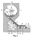
- FIG. 2 is a vertical cross-sectional view of the part-conveying apparatus in FIG. 1;
- FIG. 3 is a cross-sectional view enlarged along the line III-III in FIG. 1;
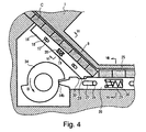
- FIG. 4 is selectively-enlarged view in which a conveying blade is returned backward in the part-conveying apparatus in FIG. 1;
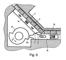
- FIG. 5 is selectively-enlarged view in which the conveying blade is forwarding in the part-conveying apparatus in FIG. 1;
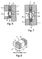
- FIG. 6 is a cross-sectional view enlarged along the line VI-VI in FIG. 4;
- FIG. 7 is a cross-sectional view enlarged along the line VII-VII in FIG. 4;
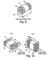
- FIG. 8 is a perspective view of an example of chip parts used in the present invention;
- FIG. 9 is a perspective view of another example of chip parts used in the present invention;
- FIG. 10 is a perspective view of yet another example of chip parts used in the present invention;
- FIG. 11 is a cross-sectional view of a second embodiment according to the present invention; and
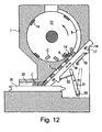
- FIG. 12 is a cross-sectional view of a third embodiment according to the present invention.
-
- FIGS. 1 to 7 are various views of a first embodiment of a part-conveying apparatus according to the present invention. In this embodiment, a rectangular chip part C, as shown in FIG. 8, having the following dimensions is used: height = H, width = W, and length = L (H ≈ W; L > H; and L > W). However, as shown in FIGS. 8 and 9, the chip parts C may be cylindrically shaped and rectangularly shaped with the following dimensions: for the cylindrically shaped part, diameter = d, height = H, width = W, and length = L (d ≈ W and H; and L > d); and for the rectangularly shaped part, height = H, width = W, and length = L (L > W > H). In these drawings, Ca and Cb denote electrodes formed at two ends in the length direction of the individual parts C.
- FIGS. 1 and 2 are overall views of the part-conveying apparatus. The apparatus is composed of three divisions: a part-aligning division in an upper portion, a part-ejecting division in a lower portion, and a part-chute division in an intermediate portion.
- It will be noted that the parts C appear relatively large in the drawings, but actual parts are very small.
- First, the part-aligning division is described below.
- The part-aligning division has a circular
concave section 2 formed in a main body 1, and arotating drum 11 fitted in theconcave section 2 so as to be rotatable. In a central portion of theconcave section 2, anaxis 3 is arranged, and a bearing section 4 is arranged to rotatably journal theaxis 3. On an inner peripheral surface of theconcave section 2, a part-aligninggroove 5 is formed in a semicircular arc shape whose width and depth are designed to have a constant clearance allowing the parts C of the width W and height H to pass through. As shown in FIG. 3, atapered guide face 6 is formed sloping toward the part-aligninggroove 5 on the inner peripheral surface of theconcave section 2. Theguide face 6 guides the parts C into the part-aligninggroove 5. - A
gate opening 8 is formed in a lower portion of the part-aligninggroove 5. Via thegate opening 8, achute 9 is formed so as to communicate with the part-aligninggroove 5. Thechute 9 is formed substantially tangential to the part-aligninggroove 5 that is semicircular-arc shaped, sloping down at a given sliding angle. - The
gate opening 8 is formed at an intersection of the part-aligninggroove 5 and thechute 9, which are tangential to each other. Thegate opening 8 has dimensions allowing the parts C to pass through one by one in a state aligned on their sides in the length direction; that is, with the height and the width which are larger than H and W, and with the length smaller than L. Also, the width of thegate opening 8 is the same as the width of the part-aligninggroove 5. - A part-storing
space 12 is formed between the main body 1 and therotating drum 11. The part-storingspace 12 has a storing capacity for a large number of the parts C fed in via a part-feedingopening 10. Therotating drum 11 is formed preferably of a transparent material such as an acrylic resin so that the volume of the parts C therein can be checked visually. An inner peripheral surface of therotating drum 11 includes a taperedguide face 13 opposing theguide face 6. The guide face 13 guides the parts C into the part-aligninggroove 5 in the same manner as theguide face 6. - On an inner peripheral surface of a peripheral portion of the
rotating drum 11, as shown in FIG. 3, a plurality of protruding tabs 14 (two pieces are shown in the drawing) is formed at a constant angular pitch. Thetabs 14 have dimensions so as to pass over thegate opening 8 and the part-aligninggroove 5. Thetabs 14 serve to normalize the parts C jammed at thegate opening 8. - The
axis 3 is connected to a driving means, such as an electric motor, and rotates with therotating drum 11 in the direction indicated by arrow A. In the rotation, thetabs 14 push back the parts C jammed at thegate opening 8 in the direction opposite to thechute 9, thereby recovering from the jam. The rotation method for therotating drum 11 is not limited to the above, with which theaxis 3 rotates, but other methods may be employed. Also, the rotation method is not limited to a continuous rotation method, but an intermittent rotation method may be employed. - Hereinbelow, a description will be given of operation of the part-aligning division in the above configuration.
- The parts C fed from the part-feeding
opening 10 and have been stored in the part-storingspace 12 are guided by the guide faces 6 and 13, which are formed respectively in the main body 1 and therotating drum 11, into the part-aligninggroove 5. At this time, the parts C are aligned in a predetermined direction since the part-aligninggroove 5 is formed with the width and the depth which have a constant clearance so as to allow passage of parts C having the width W and the height H. - Among the aforementioned parts C, those sliding down aligning in the length direction lying down pass through the
gate opening 8 smoothly and are therefore fed to the part-ejecting division through thechute 9. On the other hand, the parts C sliding down upright are not allowed to pass through thegate opening 8, and therefore stack to block thegate opening 8. In this case, the following parts C that are also not allowed to pass through thegate opening 8 stack, causing a jam. - In the above state, when the
rotating drum 11 rotates in the direction of arrow A, thetabs 14 or the parts C pushed thereby push other parts C in the direction opposite to the ejecting direction, whereby clearing the parts C stacked at thegate opening 8. At this time, a load exerted on the parts C is only the weight of other parts C following, and no other forces except for gravity are exerted thereon. Therefore, the parts C can be easily removed or laid down without adding a heavy load. This allows the parts C to be ejected smoothly from thegate opening 8. - In the above manner, the
tabs 14 of rotatingdrum 11 remove jams occurring at thegate opening 8, but in addition, they agitate the parts C that are formed like a bridge to disturb sliding in order to expedite sliding down into the part-aligninggroove 5. When the number of the parts C in the part-storingspace 12 decreases, the number of the parts C that slide down into the part-aligninggroove 5 also decreases. However, thetabs 14 of therotating drum 11 serve to carry the parts C stored in a bottom section of the part-storingspace 12 into the part-aligninggroove 5. In this way, all the parts C in the part-storingspace 12 can be ejected. - When a large number of parts C is fed into the part-storing
space 12, their weight exerts a load on the parts C aligning in the vicinity of thegate opening 8. In this case, the load probably disturbs the flow of the parts C. However, since thetabs 14 of therotating drum 11 regularly pass by thegate opening 8 and relieve the stress, the parts C are allowed to pass through thegate opening 8 smoothly. - Hereinbelow, the part-chute division is described.
- In the sloped
chute 9, which comprises the part-chute division, a lateral section is open in a region from a middle section to a lower section, and the open area is blocked by alateral cover 15. A mobile blade (mobile member) 16 is provided in a bottom section of thechute 9 so as to be slidable in the direction of thechute 9. Themobile blade 16 slidably supports bottom surfaces of the parts C. - Specifically, the
mobile blade 16 is made of a thin metal plate whose thickness is substantially the same as the width W or the height H of the part C, and as shown in FIG. 4. Long holes 17 each extending in the length direction are individually formed in front and rear portions of themobile blade 16, and guidepins 18 protruding from the main body I are fitted into thelong holes 17 so as to be slidable. In this manner, themobile blade 16 is slidably guided in the direction of thechute 9. A stroke of themobile blade 16 is limited within the range of thelong hole 17, the range being smaller than the length L of the part C. - A spring-
holder hole 19 is formed in a central portion of themobile blade 16 to store aspring 20. As shown in FIG. 6, two sides in the radial direction of thespring 20 are respectively engaged with aconcave section 21 formed on the main body 1 and with anopening 22 formed in thelateral cover 15, continuously urging down themobile blade 16 in a diagonal direction. In a lower end portion of themobile blade 16, an projection (engaging section) 23 is formed to engage with a conveyingblade 26 that is described below. - Hereinbelow, a description will be given of the part-ejecting division.
- A lower end section of the
chute 9 is connected to a rear end section of ahorizontal guide path 25 into which the parts C that have slid down thechute 9 are carried. A lateral section of theguide path 25 is open and is blocked by thelateral cover 15. In a bottom section of theguide path 25, the conveying blade (conveying member) 26 is arranged so as to be movable forward and backward. - The conveying
blade 26 slidably supports bottom surfaces of the parts C. Similarly to themobile blade 16, themobile blade 26 is made of a thin metal plate whose thickness is substantially the same as the width W or the height H of the part C. As shown in FIG. 4, long holes 27 each extending in the length direction are individually formed in front and rear portions of the conveyingblade 26, and guidepins 28 protruding from the main body 1 are slidably fitted into the long holes 27. In this manner, themobile blade 26 is guided so as to be movable horizontally in the back and front direction. A plurality of spring-holder holes 29 is formed in themobile blade 26, each of them retaining aspring 30. - As shown in FIG. 7, two sides in the radial direction of the
spring 30 are engaged respectively with aconcave section 31 formed on the main body 1 and with anopening 32 formed in thelateral cover 15, always urging themobile blade 26 backward. - As shown in FIG. 4, on an upper surface in a rear section of the conveying
blade 26, an shallow groove (engaging section) 33 is formed engageable with theprojection 23, which is formed in the lower end section of themobile blade 16. Theprojection 23 and thegroove 33 comprise a driving means that finely moves themobile blade 16 in the direction of thechute 9. - In a rear portion of the conveying
blade 26, there is provided acam 34 for reciprocating the conveyingblade 26 in a manner so as to move backward faster than to move forward. The rear portion of the conveyingblade 26 is urged by thespring 30 so as to contact a peripheral surface of thecam 34. Thespring 30 and thecam 34 compose a conveying means for reciprocating the conveyingblade 26. - The
cam 34 has acrest section 34a and avalley section 34b and is rotationally driven by means of a motor (not shown) in the direction indicated by arrow B. When a rear end section of the conveyingblade 26 proceeds over thecrest section 34a of thecam 34, the conveyingblade 26 advances at a low speed; when the rear end section comes down to thevalley section 34b of thecam 34, the conveyingblade 26 returns at a high speed. - The advancing speed of the conveying
blade 26 is specified so that a predetermined supporting frictional force operates between the conveyingblade 26 and the parts C sliding thereon. On the other hand, the returning speed of the conveyingblade 26 is specified so that the supporting frictional forces are substantially discontinued between the conveyingblade 26 and the parts C sliding thereon. Therefore, during backward and forward reciprocating movements of the conveyingblade 26, the parts C placed thereon are conveyed forward intermittently. Consecutively, the parts C conveyed to a front end section of theguide path 25 are ejected one by one at anejection position 35 by means of an ejecting device (not shown), such as that called a chip mounter. - In repetition of each reciprocating movement of the conveying
blade 26, theprojection 23 of themobile blade 16 repeats the operation of falling intogroove 33 and rising therefrom, thereby allowing themobile blade 16 to finely move in the direction of thechute 9. Specifically, as shown in FIG. 4, when the conveyingblade 26 is positioned at a rear end section, theprojection 23 is fallen inside thegroove 33 with themobile blade 16 being positioned at the lower end. When thecam 34 rotates to move the conveyingblade 26 forward, as shown in FIG. 5, theprojection 23 rises over an upper surface of the conveyingblade 26 with themobile blade 16 moving upward. In this manner, themobile blade 16 is finely moved in the direction of thechute 9, whereby the friction between themobile blade 16 and the parts C can be discontinued. Therefore, the parts C are allowed to slide down thechute 9 smoothly even when the parts C are of a small mass, are dirty, or are electrostatically charged. - In the above case, even at a small slope angle in the
chute 9, the parts C are easily allowed to slide down smoothly. This allows reduction of the angle at which thechute 9 and theguide path 25 intersect, and the parts C can thereby be caused to move smoothly from thechute 9 into theguide path 25. - In the above embodiment, as the engaging sections, the
projection 23 is provided at the lower end of themobile blade 16, and thegroove 33 is provided on the upper surface of the conveyingblade 26. However, a projection arranged on an upper surface of the conveyingblade 26 provides the same effects as above. - FIG. 11 is view of a second embodiment according to the present invention.
- In the second embodiment, a conveying
blade 16 is oscillated and moved perpendicular to achute 9, thereby discontinuing friction occurring between themobile blade 16 and the parts C. Specifically, an upper end section of themobile blade 16 is supported by anaxis 40 so as to oscillate and move and remains at a lower position to which it has been oscillated and moved by gravity. - A
projection 41 is formed on an upper surface of a conveyingblade 26. When the conveyingblade 26 is located at a rear end position, theprojection 41 is not in contact with themobile blade 16. When the conveyingblade 26 moves to a front end position, theprojection 41 oscillates and moves themobile blade 16 upward by a fine stroke. An oscillating and moving stroke of the conveyingblade 26 must be restricted so that the parts C on the conveyingblade 26 are not sandwiched between the surface thereof and an upward internal surface of achute 9. - In the above arrangement also, the
mobile blade 16 is caused to oscillate and move synchronously with the forward and backward movement of the conveyingblade 26, whereby the parts C on themobile blade 16 are allowed to slide down smoothly. - FIG. 12 is a view of a third embodiment according to the present invention.
- In the third embodiment, a
mobile blade 16 is provided in an entire region of achute 9. Similarly to the first embodiment, themobile blade 16 is guided bylong holes 17 and pins 18 so as to be movable only by a constant distance in the direction of thechute 9. - A
first spring 50 is provided between a rear end section of themobile blade 16 and a main body 1. Thefirst spring 50 urges down themobile blade 16 diagonally. Alever 51 is provided so as to oscillate and move around an axis 53 in the direction ofchute 9. Asecond spring 52 is provided between thelever 51 and a front end section of themobile blade 16. As the first and second springs, compression springs are used in this embodiment, but these springs may be replaced by tension springs. - In an initial condition, as shown in FIG. 12, the
mobile blade 16 is moved by a force of thefirst spring 50 in a lower position and is in contact with or close to the conveyingblade 26. Thelever 51 is pulled by a force of thesecond spring 52, and as a result of oscillating and moving motion, it is located in a left position in FIG. 12. - As indicated by a double-dotted line in FIG. 12, when the
lever 51 is oscillated and moved to the right, thesecond spring 52 is pulled, in which the springing force of thesecond spring 52 is increased to be greater than the springing force of thefirst spring 50. Therefore, themobile blade 16 is pulled up diagonally by means of thesecond spring 52. - When the
lever 51 is oscillated and moved toward the left, the state repeatedly becomes as shown in FIG. 12. In this way, repetition of these operations causes fine movements of themobile blade 16 in the direction of thechute 9. This discontinues friction occurring between themobile blade 16 and the parts C, thereby allowing the parts C to slide down thechute 9 smoothly. - In the above embodiment, the stroke of the
mobile blade 16 is determined bylong holes 17 and pins 18. Therefore, even though thelever 51 is oscillated and moved by a long distance, the stroke of themobile blade 16 is in fact not effected. This allows an arrangement of a driving mechanism for thelever 51 to be selective. In addition, themobile blade 16 and the conveyingblade 26 are not directly engaged with each other, whereby producing the advantage of less abrasion. - In the third embodiment, the
first spring 50 is provided between the main body I and themobile blade 16. However, it may be provided between themobile blade 16 and thelever 51. That is, the respective first andsecond springs lever 51. Furthermore, effects equivalent to the above can be implemented even in a arrangement such as in which one end of thesecond spring 52 is connected to the main body 1, and one end of thefirst spring 50 is connected to themobile blade 16. - Furthermore, in the above embodiments, blades are used as mobile members and conveying members, but there is no restriction thereto. The present invention may use other members if they are movable in a predetermined direction. However, thin members such as the blades used in these embodiments achieves a reduction in weight, so that inertia effects can be also reduced. This allows the driving mechanism to be simple.
- Furthermore, the parts that can be conveyed by the present invention are not restricted to chip parts, but any types of parts may be conveyed as long as they are conveyable through the chute in a state in which they are aligned.
Claims (3)
- A part-conveying apparatus comprising:a chute (9) sloped for aligning and sliding down parts (C),a mobile member (16) for slidably supporting the parts in a bottom section of said chute (9) either in the direction of or perpendicular to said chute (9) so as to be movable, anddriving means (23, 33) for finely moving said mobile member (16) either in the direction of or perpendicular to said chute.
- A part-conveying apparatus as claimed in claim 1, comprising:a horizontal guide path (25) connected to the lower end section of said chute (9) to align and guide parts (C);a conveying member (26) in a bottom section of said horizontal guide path (25) arranged to be movable forward and backward, andconveying means (30, 34) for reciprocating said conveying member (26) so as to move backward faster than to move forward and for conveying forward the parts (C) on an upper surface of said conveying member (26);wherein said driving means is used as an engaging section (33) formed between said mobile member (16) and said conveying member (26) to finely move the mobile member (16) either in the direction of said chute (9) or perpendicular to said chute (9) in coincidence with forward and backward movement of said conveying member (26).
- A part-conveying apparatus as claimed in claim 1, comprising a guiding means (17, 18) for guiding said mobile member (16) so as to be movable by a constant distance in the direction of said chute (9), wherein said driving means comprising:a first spring (50) for urging down said mobile member,a second spring (52) for urging up said mobile member, anda lever (51) to which at least one of said first spring (50) and said second spring (52) is connected so as to oscillate and move in the direction of said chute (9);wherein said lever (51) is oscillated and moved in a first direction to increase a spring force of said second spring (52) to be greater than a spring force of said first spring (51) so as to move up said mobile member (16), andsaid lever (51) is oscillated and moved in a second direction to increase a spring force of said first spring (50) to be greater than a spring force of said second spring (52) so as to move down said mobile member (16).
Applications Claiming Priority (2)
| Application Number | Priority Date | Filing Date | Title |
|---|---|---|---|
| JP18835698A JP3539618B2 (en) | 1998-07-03 | 1998-07-03 | Parts transfer device |
| JP18835698 | 1998-07-03 |
Publications (2)
| Publication Number | Publication Date |
|---|---|
| EP0968939A1 true EP0968939A1 (en) | 2000-01-05 |
| EP0968939B1 EP0968939B1 (en) | 2004-06-23 |
Family
ID=16222199
Family Applications (1)
| Application Number | Title | Priority Date | Filing Date |
|---|---|---|---|
| EP99305071A Expired - Lifetime EP0968939B1 (en) | 1998-07-03 | 1999-06-28 | Part-conveying apparatus |
Country Status (8)
| Country | Link |
|---|---|
| US (1) | US6257394B1 (en) |
| EP (1) | EP0968939B1 (en) |
| JP (1) | JP3539618B2 (en) |
| CN (1) | CN1118427C (en) |
| DE (1) | DE69918223D1 (en) |
| MY (1) | MY117430A (en) |
| SG (1) | SG74151A1 (en) |
| TW (1) | TW446676B (en) |
Cited By (8)
| Publication number | Priority date | Publication date | Assignee | Title |
|---|---|---|---|---|
| WO2004042381A2 (en) * | 2002-11-04 | 2004-05-21 | Kimberly-Clark Worldwide, Inc. | Method and device for stacking and packaging of articles |
| US6823981B2 (en) | 2002-11-04 | 2004-11-30 | Kimberly-Clark Worldwide, Inc. | Conveyor system for an automatic accumulation system |
| US6877294B2 (en) | 2002-11-04 | 2005-04-12 | Kimberly-Clark Worldwide, Inc. | Automatic repacking and accumulation system |
| US6884016B2 (en) | 2002-11-04 | 2005-04-26 | Kimberly-Clark Worldwide, Inc. | Positioning system for an automatic accumulation system |
| US6918485B2 (en) | 2002-11-04 | 2005-07-19 | Kimberly-Clark Worldwide, Inc. | Orientation detection and control system |
| US7108155B2 (en) | 2002-11-04 | 2006-09-19 | Kimberly-Clark Worldwide, Inc. | Metering drum for an automatic accumulation system |
| US7159375B2 (en) | 2003-10-08 | 2007-01-09 | Kimberly-Clark Worldwide, Inc. | Multi-product accumulating and packing system |
| EP2130791A4 (en) * | 2007-04-04 | 2016-11-16 | Sanki Company Ltd | Neutralization apparatus and method for part feeder |
Families Citing this family (12)
| Publication number | Priority date | Publication date | Assignee | Title |
|---|---|---|---|---|
| CN101306763B (en) * | 2008-05-13 | 2011-06-15 | 郑卫星 | Workpiece conveying device |
| CN201227799Y (en) * | 2008-07-03 | 2009-04-29 | 鸿富锦精密工业(深圳)有限公司 | Screw nail supplier |
| CN102050327A (en) * | 2010-09-28 | 2011-05-11 | 慈溪市贝瑞软件有限公司 | Guide rail device in clip threading machine |
| EP2729394B2 (en) * | 2011-07-05 | 2021-05-05 | Conceptromec Inc. | Clip separating system, kit for assembling the same |
| CN102826365A (en) * | 2012-09-17 | 2012-12-19 | 天通(六安)电子材料科技有限公司 | Automatic arrangement ink-jet printer device for magnetic ring |
| KR101871700B1 (en) * | 2014-02-27 | 2018-06-27 | 가부시키가이샤 무라타 세이사쿠쇼 | Aligning/feeding apparatus and aligning method |
| CN106241226B (en) * | 2016-08-31 | 2018-09-14 | 赛特威尔电子股份有限公司 | A kind of transmission device |
| CN106271511B (en) * | 2016-08-31 | 2018-06-08 | 赛特威尔电子股份有限公司 | A kind of transmission device in adjustable workpiece direction |
| CN106239094B (en) * | 2016-08-31 | 2018-05-29 | 赛特威尔电子股份有限公司 | A kind of transmission device in adjust automatically workpiece direction |
| CN106312499B (en) * | 2016-08-31 | 2018-06-15 | 赛特威尔电子股份有限公司 | A kind of transmitting tube transmission device |
| CN109533885A (en) * | 2018-11-15 | 2019-03-29 | 吴建德 | A kind of kitchen waste oil bottoms conveying device |
| JP7435515B2 (en) * | 2021-03-17 | 2024-02-21 | 株式会社村田製作所 | Parts storage device |
Citations (6)
| Publication number | Priority date | Publication date | Assignee | Title |
|---|---|---|---|---|
| US4732296A (en) * | 1985-06-14 | 1988-03-22 | Michael Heck | Track feed arrangement for an automatic screw feeding machine |
| JPS63127600A (en) | 1986-11-17 | 1988-05-31 | 日東工業株式会社 | Apparatus for separating and arranging chips with cartridge type chip case |
| GB2244482A (en) * | 1990-05-31 | 1991-12-04 | Taiyo Yuden Kk | Parts dispensing device |
| EP0683625A2 (en) * | 1994-05-18 | 1995-11-22 | Taiyo Yuden Co., Ltd. | Apparatus for supplying chip parts and method for same |
| JPH08222890A (en) | 1995-02-16 | 1996-08-30 | Matsushita Electric Ind Co Ltd | Electronic parts supply device |
| US5702028A (en) * | 1995-10-30 | 1997-12-30 | Ykk Corporation | Parts feeder |
Family Cites Families (1)
| Publication number | Priority date | Publication date | Assignee | Title |
|---|---|---|---|---|
| IT1249025B (en) * | 1990-06-29 | 1995-02-11 | Savio Spa | DEVICE FOR THE SEQUENTIAL LOADING OF TUBES ADJUSTABLE TO A THREADING MACHINE |
-
1998
- 1998-07-03 JP JP18835698A patent/JP3539618B2/en not_active Expired - Lifetime
-
1999
- 1999-06-22 TW TW088110405A patent/TW446676B/en not_active IP Right Cessation
- 1999-06-25 SG SG1999003437A patent/SG74151A1/en unknown
- 1999-06-28 DE DE69918223T patent/DE69918223D1/en not_active Expired - Fee Related
- 1999-06-28 EP EP99305071A patent/EP0968939B1/en not_active Expired - Lifetime
- 1999-06-30 US US09/343,701 patent/US6257394B1/en not_active Expired - Lifetime
- 1999-06-30 CN CN99108953.7A patent/CN1118427C/en not_active Expired - Lifetime
- 1999-06-30 MY MYPI99002758A patent/MY117430A/en unknown
Patent Citations (6)
| Publication number | Priority date | Publication date | Assignee | Title |
|---|---|---|---|---|
| US4732296A (en) * | 1985-06-14 | 1988-03-22 | Michael Heck | Track feed arrangement for an automatic screw feeding machine |
| JPS63127600A (en) | 1986-11-17 | 1988-05-31 | 日東工業株式会社 | Apparatus for separating and arranging chips with cartridge type chip case |
| GB2244482A (en) * | 1990-05-31 | 1991-12-04 | Taiyo Yuden Kk | Parts dispensing device |
| EP0683625A2 (en) * | 1994-05-18 | 1995-11-22 | Taiyo Yuden Co., Ltd. | Apparatus for supplying chip parts and method for same |
| JPH08222890A (en) | 1995-02-16 | 1996-08-30 | Matsushita Electric Ind Co Ltd | Electronic parts supply device |
| US5702028A (en) * | 1995-10-30 | 1997-12-30 | Ykk Corporation | Parts feeder |
Cited By (9)
| Publication number | Priority date | Publication date | Assignee | Title |
|---|---|---|---|---|
| WO2004042381A2 (en) * | 2002-11-04 | 2004-05-21 | Kimberly-Clark Worldwide, Inc. | Method and device for stacking and packaging of articles |
| WO2004042381A3 (en) * | 2002-11-04 | 2004-09-02 | Kimberly Clark Co | Method and device for stacking and packaging of articles |
| US6823981B2 (en) | 2002-11-04 | 2004-11-30 | Kimberly-Clark Worldwide, Inc. | Conveyor system for an automatic accumulation system |
| US6877294B2 (en) | 2002-11-04 | 2005-04-12 | Kimberly-Clark Worldwide, Inc. | Automatic repacking and accumulation system |
| US6884016B2 (en) | 2002-11-04 | 2005-04-26 | Kimberly-Clark Worldwide, Inc. | Positioning system for an automatic accumulation system |
| US6918485B2 (en) | 2002-11-04 | 2005-07-19 | Kimberly-Clark Worldwide, Inc. | Orientation detection and control system |
| US7108155B2 (en) | 2002-11-04 | 2006-09-19 | Kimberly-Clark Worldwide, Inc. | Metering drum for an automatic accumulation system |
| US7159375B2 (en) | 2003-10-08 | 2007-01-09 | Kimberly-Clark Worldwide, Inc. | Multi-product accumulating and packing system |
| EP2130791A4 (en) * | 2007-04-04 | 2016-11-16 | Sanki Company Ltd | Neutralization apparatus and method for part feeder |
Also Published As
| Publication number | Publication date |
|---|---|
| JP3539618B2 (en) | 2004-07-07 |
| CN1241524A (en) | 2000-01-19 |
| US6257394B1 (en) | 2001-07-10 |
| DE69918223D1 (en) | 2004-07-29 |
| TW446676B (en) | 2001-07-21 |
| MY117430A (en) | 2004-06-30 |
| SG74151A1 (en) | 2000-07-18 |
| EP0968939B1 (en) | 2004-06-23 |
| CN1118427C (en) | 2003-08-20 |
| JP2000016558A (en) | 2000-01-18 |
Similar Documents
| Publication | Publication Date | Title |
|---|---|---|
| US6257394B1 (en) | Part-conveying apparatus | |
| US5131899A (en) | Magazine and method of feeding articles | |
| US2825126A (en) | Fastener slider assembly machine | |
| US4322068A (en) | Receiving hopper for documents | |
| US11299349B2 (en) | Bolt supply device | |
| EP0729119A2 (en) | Coin conveying device | |
| KR0122599B1 (en) | Coin receiving and discharging apparatus | |
| EP0469886B1 (en) | Coin conveyor for successively transporting coins | |
| US5730317A (en) | Structure of chip component feeder | |
| JP3244046B2 (en) | Parts transfer device | |
| US5170874A (en) | Coin conveyor for successively transporting coins | |
| US6209713B1 (en) | Part transfer apparatus | |
| US6513644B1 (en) | Apparatus and method for aligning parts | |
| US6112937A (en) | Apparatus and method for aligning parts | |
| EP0690419A1 (en) | Coin delivering apparatus | |
| US4148475A (en) | Sheet sorting device | |
| KR100902111B1 (en) | Card dispensing apparatus | |
| US3291485A (en) | Record card stacking apparatus | |
| JP7462323B2 (en) | Coin dispensing device and coin processing device | |
| RU2208507C2 (en) | Charging-bin apparatus for rod type parts | |
| US20200312076A1 (en) | Coin handling apparatus | |
| JP7199062B2 (en) | Disc body guide device | |
| JP2006252080A (en) | Conveyer for coin | |
| US7455579B2 (en) | Overflow chute apparatus for coin storing | |
| SU1511052A1 (en) | Device for orienting cylindrical parts having an annular slot |
Legal Events
| Date | Code | Title | Description |
|---|---|---|---|
| PUAI | Public reference made under article 153(3) epc to a published international application that has entered the european phase |
Free format text: ORIGINAL CODE: 0009012 |
|
| 17P | Request for examination filed |
Effective date: 19990707 |
|
| AK | Designated contracting states |
Kind code of ref document: A1 Designated state(s): DE FR GB |
|
| AX | Request for extension of the european patent |
Free format text: AL;LT;LV;MK;RO;SI |
|
| AKX | Designation fees paid |
Free format text: DE FR |
|
| RBV | Designated contracting states (corrected) |
Designated state(s): DE FR GB |
|
| 17Q | First examination report despatched |
Effective date: 20020523 |
|
| GRAP | Despatch of communication of intention to grant a patent |
Free format text: ORIGINAL CODE: EPIDOSNIGR1 |
|
| GRAS | Grant fee paid |
Free format text: ORIGINAL CODE: EPIDOSNIGR3 |
|
| GRAA | (expected) grant |
Free format text: ORIGINAL CODE: 0009210 |
|
| AK | Designated contracting states |
Kind code of ref document: B1 Designated state(s): DE FR GB |
|
| PG25 | Lapsed in a contracting state [announced via postgrant information from national office to epo] |
Ref country code: FR Free format text: LAPSE BECAUSE OF FAILURE TO SUBMIT A TRANSLATION OF THE DESCRIPTION OR TO PAY THE FEE WITHIN THE PRESCRIBED TIME-LIMIT Effective date: 20040623 |
|
| REG | Reference to a national code |
Ref country code: GB Ref legal event code: FG4D |
|
| REF | Corresponds to: |
Ref document number: 69918223 Country of ref document: DE Date of ref document: 20040729 Kind code of ref document: P |
|
| PG25 | Lapsed in a contracting state [announced via postgrant information from national office to epo] |
Ref country code: DE Free format text: LAPSE BECAUSE OF NON-PAYMENT OF DUE FEES Effective date: 20050101 |
|
| PLBE | No opposition filed within time limit |
Free format text: ORIGINAL CODE: 0009261 |
|
| STAA | Information on the status of an ep patent application or granted ep patent |
Free format text: STATUS: NO OPPOSITION FILED WITHIN TIME LIMIT |
|
| 26N | No opposition filed |
Effective date: 20050324 |
|
| EN | Fr: translation not filed | ||
| PGFP | Annual fee paid to national office [announced via postgrant information from national office to epo] |
Ref country code: GB Payment date: 20180620 Year of fee payment: 20 |
|
| REG | Reference to a national code |
Ref country code: GB Ref legal event code: PE20 Expiry date: 20190627 |
|
| PG25 | Lapsed in a contracting state [announced via postgrant information from national office to epo] |
Ref country code: GB Free format text: LAPSE BECAUSE OF EXPIRATION OF PROTECTION Effective date: 20190627 |