EP0973151A2 - Noise control system - Google Patents
Noise control system Download PDFInfo
- Publication number
- EP0973151A2 EP0973151A2 EP99113651A EP99113651A EP0973151A2 EP 0973151 A2 EP0973151 A2 EP 0973151A2 EP 99113651 A EP99113651 A EP 99113651A EP 99113651 A EP99113651 A EP 99113651A EP 0973151 A2 EP0973151 A2 EP 0973151A2
- Authority
- EP
- European Patent Office
- Prior art keywords
- output
- coefficient
- digital filter
- noise
- receives
- Prior art date
- Legal status (The legal status is an assumption and is not a legal conclusion. Google has not performed a legal analysis and makes no representation as to the accuracy of the status listed.)
- Granted
Links
Images


Classifications
-
- G—PHYSICS
- G10—MUSICAL INSTRUMENTS; ACOUSTICS
- G10K—SOUND-PRODUCING DEVICES; METHODS OR DEVICES FOR PROTECTING AGAINST, OR FOR DAMPING, NOISE OR OTHER ACOUSTIC WAVES IN GENERAL; ACOUSTICS NOT OTHERWISE PROVIDED FOR
- G10K11/00—Methods or devices for transmitting, conducting or directing sound in general; Methods or devices for protecting against, or for damping, noise or other acoustic waves in general
- G10K11/16—Methods or devices for protecting against, or for damping, noise or other acoustic waves in general
- G10K11/175—Methods or devices for protecting against, or for damping, noise or other acoustic waves in general using interference effects; Masking sound
- G10K11/178—Methods or devices for protecting against, or for damping, noise or other acoustic waves in general using interference effects; Masking sound by electro-acoustically regenerating the original acoustic waves in anti-phase
- G10K11/1781—Methods or devices for protecting against, or for damping, noise or other acoustic waves in general using interference effects; Masking sound by electro-acoustically regenerating the original acoustic waves in anti-phase characterised by the analysis of input or output signals, e.g. frequency range, modes, transfer functions
- G10K11/17821—Methods or devices for protecting against, or for damping, noise or other acoustic waves in general using interference effects; Masking sound by electro-acoustically regenerating the original acoustic waves in anti-phase characterised by the analysis of input or output signals, e.g. frequency range, modes, transfer functions characterised by the analysis of the input signals only
- G10K11/17825—Error signals
-
- G—PHYSICS
- G10—MUSICAL INSTRUMENTS; ACOUSTICS
- G10K—SOUND-PRODUCING DEVICES; METHODS OR DEVICES FOR PROTECTING AGAINST, OR FOR DAMPING, NOISE OR OTHER ACOUSTIC WAVES IN GENERAL; ACOUSTICS NOT OTHERWISE PROVIDED FOR
- G10K11/00—Methods or devices for transmitting, conducting or directing sound in general; Methods or devices for protecting against, or for damping, noise or other acoustic waves in general
- G10K11/16—Methods or devices for protecting against, or for damping, noise or other acoustic waves in general
- G10K11/175—Methods or devices for protecting against, or for damping, noise or other acoustic waves in general using interference effects; Masking sound
- G10K11/178—Methods or devices for protecting against, or for damping, noise or other acoustic waves in general using interference effects; Masking sound by electro-acoustically regenerating the original acoustic waves in anti-phase
- G10K11/1783—Methods or devices for protecting against, or for damping, noise or other acoustic waves in general using interference effects; Masking sound by electro-acoustically regenerating the original acoustic waves in anti-phase handling or detecting of non-standard events or conditions, e.g. changing operating modes under specific operating conditions
- G10K11/17833—Methods or devices for protecting against, or for damping, noise or other acoustic waves in general using interference effects; Masking sound by electro-acoustically regenerating the original acoustic waves in anti-phase handling or detecting of non-standard events or conditions, e.g. changing operating modes under specific operating conditions by using a self-diagnostic function or a malfunction prevention function, e.g. detecting abnormal output levels
-
- G—PHYSICS
- G10—MUSICAL INSTRUMENTS; ACOUSTICS
- G10K—SOUND-PRODUCING DEVICES; METHODS OR DEVICES FOR PROTECTING AGAINST, OR FOR DAMPING, NOISE OR OTHER ACOUSTIC WAVES IN GENERAL; ACOUSTICS NOT OTHERWISE PROVIDED FOR
- G10K11/00—Methods or devices for transmitting, conducting or directing sound in general; Methods or devices for protecting against, or for damping, noise or other acoustic waves in general
- G10K11/16—Methods or devices for protecting against, or for damping, noise or other acoustic waves in general
- G10K11/175—Methods or devices for protecting against, or for damping, noise or other acoustic waves in general using interference effects; Masking sound
- G10K11/178—Methods or devices for protecting against, or for damping, noise or other acoustic waves in general using interference effects; Masking sound by electro-acoustically regenerating the original acoustic waves in anti-phase
- G10K11/1785—Methods, e.g. algorithms; Devices
- G10K11/17853—Methods, e.g. algorithms; Devices of the filter
- G10K11/17854—Methods, e.g. algorithms; Devices of the filter the filter being an adaptive filter
-
- G—PHYSICS
- G10—MUSICAL INSTRUMENTS; ACOUSTICS
- G10K—SOUND-PRODUCING DEVICES; METHODS OR DEVICES FOR PROTECTING AGAINST, OR FOR DAMPING, NOISE OR OTHER ACOUSTIC WAVES IN GENERAL; ACOUSTICS NOT OTHERWISE PROVIDED FOR
- G10K11/00—Methods or devices for transmitting, conducting or directing sound in general; Methods or devices for protecting against, or for damping, noise or other acoustic waves in general
- G10K11/16—Methods or devices for protecting against, or for damping, noise or other acoustic waves in general
- G10K11/175—Methods or devices for protecting against, or for damping, noise or other acoustic waves in general using interference effects; Masking sound
- G10K11/178—Methods or devices for protecting against, or for damping, noise or other acoustic waves in general using interference effects; Masking sound by electro-acoustically regenerating the original acoustic waves in anti-phase
- G10K11/1787—General system configurations
- G10K11/17879—General system configurations using both a reference signal and an error signal
- G10K11/17881—General system configurations using both a reference signal and an error signal the reference signal being an acoustic signal, e.g. recorded with a microphone
-
- G—PHYSICS
- G10—MUSICAL INSTRUMENTS; ACOUSTICS
- G10K—SOUND-PRODUCING DEVICES; METHODS OR DEVICES FOR PROTECTING AGAINST, OR FOR DAMPING, NOISE OR OTHER ACOUSTIC WAVES IN GENERAL; ACOUSTICS NOT OTHERWISE PROVIDED FOR
- G10K2210/00—Details of active noise control [ANC] covered by G10K11/178 but not provided for in any of its subgroups
- G10K2210/30—Means
- G10K2210/301—Computational
- G10K2210/3012—Algorithms
-
- G—PHYSICS
- G10—MUSICAL INSTRUMENTS; ACOUSTICS
- G10K—SOUND-PRODUCING DEVICES; METHODS OR DEVICES FOR PROTECTING AGAINST, OR FOR DAMPING, NOISE OR OTHER ACOUSTIC WAVES IN GENERAL; ACOUSTICS NOT OTHERWISE PROVIDED FOR
- G10K2210/00—Details of active noise control [ANC] covered by G10K11/178 but not provided for in any of its subgroups
- G10K2210/30—Means
- G10K2210/301—Computational
- G10K2210/3027—Feedforward
-
- G—PHYSICS
- G10—MUSICAL INSTRUMENTS; ACOUSTICS
- G10K—SOUND-PRODUCING DEVICES; METHODS OR DEVICES FOR PROTECTING AGAINST, OR FOR DAMPING, NOISE OR OTHER ACOUSTIC WAVES IN GENERAL; ACOUSTICS NOT OTHERWISE PROVIDED FOR
- G10K2210/00—Details of active noise control [ANC] covered by G10K11/178 but not provided for in any of its subgroups
- G10K2210/30—Means
- G10K2210/301—Computational
- G10K2210/3039—Nonlinear, e.g. clipping, numerical truncation, thresholding or variable input and output gain
Definitions
- the present invention relates to a noise control system based on active noise control, for use in a noisy environment.
- This type of a noise control system in the conventional art employs an adaptive filter for calculating a noise control signal, and may further employ an auxiliary adaptive filter for preventing an increase in the gain of the adaptive filter, as disclosed in, for example, Japanese Laid-Open Publication No. 5-67948.
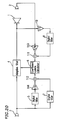
- FIG 22 is a block diagram illustrating a structure of such a conventional noise control system.
- the noise control system includes a control speaker 1 , an error detection microphone 2 which functions as an error detector, a noise detection microphone 3 which functions as a noise detector, adaptive filters 4 and 15 , a digital filter 5 which approximates the propagation characteristic between the control speaker 1 and the error detection microphone 2 , coefficient update calculators 6 and 9 , and a digital filter 7 having a frequency band limiting characteristic.
- noise generated from a noise source is detected by the noise detector 3 , and a noise source signal is generated based on the detection result.
- the generated noise source signal is processed by the adaptive filter 4 , so as to output a control signal.
- a control sound is generated from the control speaker 1 based on the control signal so that the control sound interferes with the noise from the noise source, thereby reducing the noise.
- the state of interference between the control sound output from the control speaker 1 and the noise is measured by the error detector (microphone) 2 .
- the output of the error detector (microphone) 2 should ideally be zero as a result of the noise control. Therefore, the coefficient update calculator 6 performs a calculation such that the output signal of the error detector (microphone) 2 is reduced, and controls the coefficient of the adaptive filter 4 based on the calculation result.
- the coefficient update calculator 9 performs a calculation such that the output of the adaptive filter 15 is reduced, and controls the coefficient of the adaptive filter 15 based on the calculation result.
- a band limiting signal produced by the digital filter 7 is input to the adaptive filter 15 , and the coefficient of the adaptive filter 15 converges into a value which suppresses signals in the band.
- the coefficients of the adaptive filters 4 and 15 can be shared by each other so as to combine the effects of the two coefficient update calculators 6 and 9 together, and the update operation of the coefficient of the adaptive filter 4 is suppressed in a band which is set in the digital filter 7 .
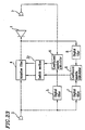
- FIG 23 is a block diagram illustrating a structure of another conventional noise control system as disclosed in Japanese Laid-Open Publication No. 7-271383.
- the noise control system includes a control speaker 1 , an error detection microphone 2 which functions as an error detector, a noise detection microphone 3 which functions as a noise detector, an adaptive filter 4 , a digital filter 5 which approximates the propagation characteristic between the control speaker 1 and the error detection microphone 2 , coefficient update calculators 6 and 9 , digital filters 7 and 8 each having a frequency band limiting characteristic, and a switch section 32 .
- noise generated from a noise source is detected by the noise detector 3 , and a noise source signal is generated based on the detection result.
- the generated noise source signal is processed by the adaptive filter 4 , so as to output a control signal.
- a control mound is generated from the control speaker 1 based on the control signal so that the control sound interferes with the noise from the noise source, thereby reducing the noise.
- the state, of interference between the control sound output from the control speaker 1 and the noise is measured by the error detector (microphone) 2 .
- the output of the error detector (microphone) 2 should ideally be zero as a result of the noise control. Therefore, the coefficient update calculator 6 performs a calculation such that the output signal of the error detector (microphone) 2 is reduced.
- a band limiting signal produced by the digital filter 7 and another band limiting signal produced by the digital filter 8 are input to the coefficient update calculator 9 , and the coefficient update calculator 9 performs a coefficient update calculation such that the adaptive filter 4 suppresses the output of the signal in the band.
- the switch section 32 switches between the outputs of the coefficient update calculators 6 and 9 , so as to control the update operation of the band limitation by the digital filters 7 and 8 .
- the conventional noise control system as illustrated in Figure 22 requires the auxiliary adaptive filter 15 for controlling the update operation of the coefficient of the adaptive filter 4 , thereby increasing the amount of calculation to be performed.
- the other conventional noise control system as illustrated in Figure 23 requires two coefficient update calculators 6 and 9 , thereby increasing the amount of calculation to be performed. Moreover, since the switching between the outputs of the coefficient update calculators 6 and 9 is done by the switch section 32 , coefficient update operations of the adaptive filter by the coefficient update calculators 6 and 9 cannot be arbitrarily weighed.
- a noise control system of the present invention includes: a control sound generator for generating a control sound; an error detector for detecting an error signal between the control sound and noise; a noise detector for detecting a noise source signal; an adaptive filter for outputting a control signal; and a coefficient updator for updating a coefficient of the adaptive filter, the coefficient updator comprising at least a first digital filter, a first coefficient update calculator, a second digital filter, a phase inverter, a third digital filter, and a second coefficient update calculator.
- the coefficient updator has a function of suppressing an increase in a coefficient gain of the adaptive filter in a predetermined frequency band.
- the coefficient updator is such that: the first digital filter receives, as an input thereto, an output of the noise detector; the first coefficient update calculator receives, as inputs thereto, an output of the first digital filter and an output of the error detector; the phase inverter inverts the output of the noise detector; the second digital filter receives, as an input thereto, an output of the phase inverter; the third digital filter receives, as an input thereto, the output of the error detector; the second coefficient update calculator receives, as inputs thereto, outputs of the second and third digital filters; the first digital filter approximates a propagation characteristic between the control sound generator and the error detector; the second and third digital filters have a common passband frequency characteristic; the first coefficient update calculator performs a calculation such that the output of the error detector is reduced, and updates the coefficient of the adaptive filter based on the calculation result; and the second coefficient update calculator performs a calculation such that the output of the third digital filter is reduced, and updates the coefficient of the adaptive filter based on the output of the coefficient update
- the coefficient updator is such that: the first digital filter receives, as an input thereto, an output of the noise detector; the first coefficient update calculator receives, as inputs thereto, an output of the first digital filter and an output of the error detector; the second digital filter receives, as an input thereto, an output of the noise detector; the third digital filter receives, as an input thereto, the output of the error detector; the second coefficient update calculator receives, as inputs thereto, outputs of the second and third digital filters; the phase inverter inverts an output of the second coefficient update calculator; the first digital filter approximates a propagation characteristic between the control sound generator and the error detector; the second and third digital filters have a common passband frequency characteristic; the first coefficient update calculator performs a calculation such that the output of the error detector is reduced, and updates the coefficient of the adaptive filter based on the calculation result; and the second coefficient update calculator performs a calculation such that the output of the third digital filter is reduced, inverts and outputs the calculation result, and updates the coefficient of the adaptive
- the coefficient updator further includes: a first selection controller for thinning out the outputs of the first coefficient update calculator; a second selection controller for thinning out the outputs of the second coefficient update calculator; and a selection control calculator for receiving an output signal of the third digital filter to control the first and second selection controllers;
- the first digital filter receives, as an input thereto, an output of the noise detector;
- the first coefficient update calculator receives, as inputs thereto, an output of the first digital filter and an output of the error detector;
- the phase inverter inverts an output of the adaptive filter;
- the third digital filter receives, as an input thereto, an output of the phase inverter;
- the second coefficient update calculator receives, as inputs thereto, outputs of the second and third digital filters;
- the first digital filter approximates a propagation characteristic between the control sound generator and the error detector;
- the second and third digital filters have a common passband frequency characteristic;
- the first coefficient update calculator performs a calculation such that the output of the error detector
- the coefficient updator further includes a a first selection controller for switching between selecting an output of the first coefficient update calculator and selecting nothing; a second selection controller for switching between selecting an output of the second coefficient update calculator and selecting nothing; and a selection control calculator for receiving an output signal of the third digital filter to control the first and second selection controllers;
- the first digital filter receives, as an input thereto, an output of the noise detector;
- the first coefficient update calculator receives, as inputs thereto, an output of the first digital filter and an output of the error detector;
- the phase inverter inverts an output of the adaptive filter;
- the third digital filter receives, as an input thereto, an output of the phase inverter;
- the second coefficient update calculator receives, as inputs thereto, outputs of the second and third digital filters;
- the first digital filter approximates a propagation characteristic between the control sound generator and the error detector;
- the second and third digital filters have a common passband frequency characteristic;
- the first coefficient update calculator performs a calculation such that the output of
- the coefficient updator further includes: a signal level converter for receiving an output signal of the third digital filter to convert a level of the signal; and a multiplier for multiplying an output of the signal level converter by an output of the second coefficient update calculator so as to update the coefficient of the adaptive filter;
- the first digital filter receives, as an input thereto, an output of the noise detector;
- the first coefficient update calculator receives, as inputs thereto, an output of the first digital filter and an output of the error detector;
- the second digital filter receives, as an input thereto, the output of the noise detector;
- the phase inverter inverts an output of the adaptive filter;
- the third digital filter receives, as an input thereto, an output of the phase inverter;
- the second coefficient update calculator receives, as inputs thereto, outputs of the second and third digital filters;
- the first digital filter approximates a propagation characteristic between the control sound generator and the error detector;
- the second and third digital filters have a common passband frequency characteristic;
- the predetermined frequency band may exist in a low frequency region.
- the predetermined frequency band may be a frequency region where the frequency is less than or equal to a lower limit reproducible frequency of the control sound generator.
- Another noise control system of the present invention includes: a control sound generator for generating a control sound; an error detector for detecting an error signal between the control sound and noise; a noise detector for detecting a noise source signal; an adaptive filter for outputting a control signal; and a coefficient updator for updating a coefficient of the adaptive filter, the coefficient updator comprising at least a first digital filter, a second digital filter, a third digital filter, a coefficient update calculator, a phase inverter, a first adder, and a second adder.
- the coefficient updator has a function of suppressing an increase in a coefficient gain of the adaptive filter in a predetermined frequency band.
- the coefficient updator is such that: the first digital filter receives, as an input thereto, an output of the noise detector; the second digital filter receives, as an input thereto, the output of the noise detector; the first adder receives, as inputs thereto, an output of the first digital filter and an output of the second digital filter; the second adder receives, as inputs thereto, an output of the error detector and an output of the third digital filter; the coefficient update calculator receives, as inputs thereto, an output of the first adder and an output of the second adder; the phase inverter inverts an output of the adaptive filter; the third digital filter receives, as an input thereto, the output of the phase inverter; the first digital filter approximates a propagation characteristic between the control sound generator and the error detector; the second and third digital filters have a common passband frequency characteristic; and the coefficient update calculator performs a calculation such that the output of the second adder is reduced, and updates the coefficient of the adaptive filter based on the calculation result.
- the coefficient updator is such that: the first digital filter receives, as an input thereto, an output of the noise detector; the phase inverter inverts the output of the noise detector: the second digital filter receives, as an input thereto, the output of the phase inverter; the first adder receives, as inputs thereto, an output of the first digital filter and an output of the second digital filter; the second adder receives, as inputs thereto, an output of the error detector and an output of the third digital filter; the coefficient update calculator receives, as inputs thereto, an output of the first adder and an output of the second adder; the third digital filter receives, as an input thereto, an output of the adaptive filter; the first digital filter approximates a propagation characteristic between the control sound generator and the error detector; the second and third digital filters have a common passband frequency characteristic; and the coefficient update calculator performs a calculation such that the output of the second adder is reduced, and updates the coefficient of the adaptive filter based on the calculation result.
- the coefficient updator further includes: a first coefficient controller for multiplying an output of the second digital filter by a first coefficient factor; and a second coefficient controller for multiplying an output of the third digital filter by a second coefficient factor;
- the first digital filter receives, as an input thereto, an output of the noise detector;
- the second digital filter receives, as an input thereto, the output of the noise detector;
- the first adder receives, as inputs thereto, an output of the first digital filter and an output of the first coefficient controller;
- the second adder receives, as inputs thereto, an output of the error detector and an output of the second coefficient controller;
- the coefficient update calculator receives, as inputs thereto, an output of the first adder and an output of the second adder;
- the phase inverter inverts an output of the adaptive filter;
- the third digital filter receives, as an input thereto, the output of the phase inverter; each of the first coefficient factor and the second coefficient factor is set to be equal to or more than 1; the first
- the first coefficient controller may be set so that in a passband of the second digital filter, the output of the first coefficient controller is larger than an output signal of the first digital filter.
- the second coefficient controller may be set so that in a passband of the third digital filter, the output of the second coefficient controller is larger than an output signal of the error detector.
- the coefficient updator further includes: a first coefficient controller for multiplying an output of the first digital filter by a first coefficient factor; and a second coefficient controller for multiplying an output of the error detector by a second coefficient factor;
- the first digital filter receives, as an input thereto, an output of the noise detector;
- the second digital filter receives, as an input thereto, the output of the noise detector;
- the first adder receives, as inputs thereto, an output of the first coefficient controller and an output of the second digital filter;
- the second adder receives, as inputs thereto, an output of the second coefficient controller and an output of the third digital filter;
- the coefficient update calculator receives, as inputs thereto, an output of the first adder and an output of the second adder;
- the phase inverter inverts an output of the adaptive filter;
- the third digital filter receives, as an input thereto, the output of the phase inverter; each of the first coefficient factor and the second coefficient factor is set to be less than or equal to 1; the first
- the first coefficient controller may be set so that in a passband of the second digital filter, the output of the first coefficient controller is smaller than an output signal of the first digital filter.
- the second coefficient controller may be set so that in a passband of the third digital filter, the output of the second coefficient controller is smaller than an output signal of the error detector.
- the predetermined frequency band may exist in a low frequency region.
- the predetermined frequency band may be a frequency region where the frequency is less than or equal to a lower limit reproducible frequency of the control sound generator.
- the predetermined frequency band may exist in a frequency region where there is a correlation between an output signal of the noise detector and an output signal of the error detector.
- the noise detection signal and the adaptive filter output signal are processed by the band limiting digital filters, which have the same characteristic, so as to produce a coefficient update signal in the negative direction from both of the output signal, thereby controlling the adaptive filter used in a noise control calculation.
- the present invention prevents an undesired increase in the coefficient gain of the adaptive filter in the band of the above-described digital filter, while realizing a coefficient control of the adaptive filter used in a noise control calculation without having to use additional hardware such as an adaptive filter or an additional calculation process, thereby realizing a stable noise processing operation.
- the update frequency, at which the negative coefficient update for the adaptive filter is performed is controlled in view of the non-linear characteristic of the noise propagation system or the control sound generator, whereby it is possible to realize a noise control with no band limitation when the noise signal is small.
- the invention described herein makes possible the advantage of providing a noise control system capable of a stable noise processing operation by controlling the coefficient of an adaptive filter used in noise control calculations without having to provide additional hardware such as an adaptive filter or an additional calculation process.
- a low frequency band of the control signal is limited so that the adaptive filter does not generate an excessive control signal for noise having a frequency which is too low for the low band reproducibility of the control speaker.
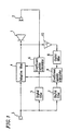
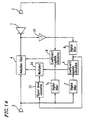
- FIG. 1 is a block diagram illustrating a structure of the noise control system of this embodiment.
- the noise control system includes a control speaker 1 , an error detection microphone 2 which functions as an error detector, a noise detection microphone 3 which functions as a noise detector, an adaptive filter 4 , a digital filter 5 which approximates the propagation characteristic between the control speaker 1 and the error detection microphone 2 , coefficient update calculators 6 and 9 , digital filters 7 and 8 each having a frequency band limiting characteristic (band limiting filters), and a phase inverter 10 for inverting the output of the adaptive filter 4 .
- noise generated from a noise source is detected by a noise detector 3 , and a noise source signal is generated based on the detection result.
- the generated noise source signal is processed by the adaptive filter 4 , so as to output a control signal.
- a control sound is generated from the control speaker 1 based on the control signal so that the control sound interferes with the noise from the noise source, thereby reducing the noise.
- the state of interference between the control sound output from the control speaker 1 and the noise is measured by the error detector (microphone) 2 .
- the output of the error detector (microphone) 2 should ideally be zero as a result of the noise control. Therefore, the coefficient update calculator 6 performs a coefficient update calculation as shown in Expression (1) later based on a filtered X-LMS method (see Widrow and Stearns, "Adaptive Signal Processing", 1985), or the like, so as to adjust the characteristic of the adaptive filter 4 , such that the output signal of the error detector (microphone) 2 is reduced. This changes the control sound actually generated from the control speaker 1 , thereby further reducing the noise.
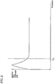
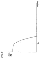
- the frequency characteristic of the control speaker 1 is such that the sound pressure of an output thereof is reduced in a frequency region where the frequency is less than or equal to the lower limit reproducible frequency f L , as shown in Figure 2 .
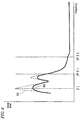
- the coefficient gain of the adaptive filter 4 is required to sufficiently reduce (or cancel) the noise in the low frequency region while compensating for the characteristic of the control speaker 1 , thereby converging into the characteristic as illustrated in Figure 3 , where the gain has an increase in the low frequency region (a region where the frequency is less than or equal to the lower limit reproducible frequency f L of the control speaker 1 ). In such a case, a large low frequency signal is input to the control speaker 1 .
- the distortion may act as an error signal, thereby causing an adverse effect such as making the operation of the adaptive filter 4 unstable.
- the digital filters 7 and 8 are set to have a band limiting characteristic with a passband characteristic as illustrated in Figure 8 in the low frequency region where the output of the control speaker 1 is reduced (e.g., the frequency region where the frequency is less than or equal to the lower limit reproducible frequency f L of the control speaker 1 ).
- the output signal of the adaptive filter 4 is inverted by the phase inverter 10 and processed by the digital filter 8 so as to obtain an error signal, while processing the output signal of the noise detector 3 by the digital filter 7 and inputting the processed signal as a reference signal to the coefficient update calculator 9 .
- the coefficient update calculator 9 performs a calculation according to Expression (2) to be described later, using an algorithm similar to that of the coefficient update calculator 6 .
- the coefficient of the adaptive filter 4 is updated by both of the coefficient update calculators 6 and 9 using an update calculation according to Expression (3) to be described later.
- the coefficient update calculator 9 operates so as to reduce the output signal of the digital filter 7 , whereby the increase in the coefficient gain of the adaptive filter 4 is suppressed in the low frequency region as illustrated by the solid line (b) in Figure 9 .
- a broken line (a) in Figure 9 is a coefficient gain of the adaptive filter 4 which is obtained by using only the coefficient update calculator 6 , illustrated in Figure 3 for updating the coefficient of the adaptive filter 4 .
- a broken line (a) in Figure 10 corresponds to the broken line (a) in Figures 4 and 7 .
- ⁇ W j denotes an output signal vector of the coefficient update calculator 6
- ⁇ U j an output signal vector of the coefficient update calculator 9
- W j a coefficient vector of the adaptive filter 4
- R j an output vector of the digital filter 5
- S j an output signal vector of the digital filter 7
- e j an output signal of the error detector
- v j an output signal of the digital filter 8 , all at time j.
- ⁇ and ⁇ are size parameters for a coefficient update step.
- the phase inverter 10 is connected between the adaptive filter 4 and the digital filter 8 .
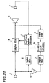
- Functions and effects similar to those described above are also obtained by the structure as illustrated in Figure 11 , where the phase inverter 10 is connected between the noise detector 3 and the digital filter 7 .
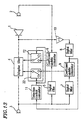
- functions and effects similar to those described above are also obtained by the structure as illustrated in Figure 12 , where the phase inverter 10 is connected to the output of the coefficient update calculator 9 , or by another structure where the phase inverter 10 is connected to the output of the digital filter 8 or the digital filter 7 .
- Elements in the block diagrams of Figures 11 and 12 corresponding to those shown in Figure 1 have like reference numerals, and will not be further described here.
- Figure 13 is a block diagram illustrating a structure of the noise control system of this embodiment. Elements in the block diagram of Figure 13 corresponding to those illustrated in Embodiment 1 with reference to, e.g., Figure 1 have like reference numerals, and will not be further described below.
- the update frequency at which the coefficient update calculation is performed by the coefficient update calculator 6 is increased while the low frequency component of the output of the adaptive filter 4 is small and the control speaker 1 is operating in the linear region.
- the update frequency at which the coefficient update calculation is performed by the coefficient update calculator 9 is increased, when the law frequency component of the output of the adaptive filter 4 increases and the control speaker 1 enters the non-linear region, so as to perform a coefficient update calculation which suppresses the filter gain in the low frequency region. In this way, it is possible not only to sufficiently reduce the noise even in the low frequency region when the noise level is low, but also to perform a stable noise control even when the noise level in the low frequency region is high.
- the illustrated noise control system includes a selector 12 for thinning out the outputs of the coefficient update calculator 6 , another selector 22 for thinning out the outputs of the coefficient update calculator 9 , and a selection control calculator 11 for controlling the operations of the selectors 12 and 22 .
- the other elements and the functions thereof are similar to those described above in Embodiment 1 .
- the selectors 12 and 22 when in the closed position, transfer the outputs of the coefficient update calculators 6 and 9 , respectively, to the adaptive filter 4 , while selecting no signal (or transferring no signal to the adaptive filter 4 ) when in the open position.
- each of the selectors 12 and 22 at a predetermined timing (frequency)
- the selector 12 is closed once for 4 sampling operations to control the adaptive filter by the output of the coefficient update calculator 6 ; and the selector 22 is closed once for 16 sampling operations to control the adaptive filter by the output of the coefficient update calculator 9 .
- the noise control operation is performed by setting the thinning-out frequency of the selector 22 to be lower than that of the selector 12 .
- a low frequency component of the output signal of the adaptive filter 4 is obtained from the digital filter 8 as an output signal thereof.
- the control speaker 1 has a non-linear characteristic in the vicinity of such a low frequency
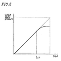
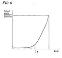
- the output sound pressure is saturated (see Figure 5 ) while the distortion increases considerably (see Figure 6 ), as illustrated in the input-output sound pressure characteristic of Figure 5 and the input-output sound pressure distortion characteristic of Figure 6 .
- noise corresponding to the broken line (a) in Figure 4
- the conventional adaptive filter 4 whose spectrum at the error detector (microphone) 2 includes signals in the vicinity of the low frequency f1, as illustrated by the broken line (a) in Figure 7
- a sufficient sound elimination cannot be realized because the control mound is saturated at the frequency f1. It may rather lead to generation of a higher harmonic wave distortion at a frequency twice or three times the frequency f1, as illustrated by a solid line (b) in Figure 7 , thereby creating new noise.
- the distortion may act as an error signal, thereby causing an adverse effect such as making the operation of the adaptive filter 4 unstable.
- the output level of a low frequency component of the output from the digital filter 8 is detected by the selection control calculator 11 and, if the output level exceeds Ls, the thinning-out frequencies of the selectors 12 and 22 are controlled so that the thinning-out frequency of the selector 22 is larger than that of the selector 12 .
- the selector 12 is closed once for 16 sampling operations so as to use the output of the coefficient update calculator 6 for updating the coefficient of the adaptive filter 4 only at this timing, thus controlling the adaptive filter 4 while thinning out the outputs of the coefficient update calculator 6 .
- the selector 22 is closed once for 4 sampling operations so as to use the output of the coefficient update calculator 9 for updating the coefficient of the adaptive filter 4 only at this timing, thus controlling the adaptive filter 4 while thinning out the outputs of the coefficient update calculator 9 .
- the coefficient of the adaptive filter 4 is updated based on an output of the coefficient update calculator 9 more often than based on an output of the coefficient update calculator 6 .
- the control speaker 1 operates in the linear region when the low frequency component of the control speaker 1 is at a small level, thereby sufficiently controlling noise which contains a low frequency component (e.g., f1), as illustrated by the solid line (b) in Figure 4 .
- a low frequency component e.g., f1
- the level of the low frequency component of the adaptive filter 4 increases and the input to the control speaker 1 exceeds the threshold level Ls to enter the non-linear region, the update operation of the coefficient of the adaptive filter 4 is restricted so as to reduce the low frequency gain.
- noise control system of the present embodiment it is possible to effectively utilize the linear operability of the control speaker 1 while suppressing the operation thereof in the non-linear region, so as to provide an optimal noise control for low frequency level noise.
- Figure 14 is a block diagram illustrating the noise control system of this embodiment. Elements in the block diagram of Figure 14 corresponding to those illustrated in Embodiment 1 with reference to, e.g., Figure 1 have like reference numerals, and will not be further described below.
- the coefficient of the adaptive filter 4 is updated in an optimal manner according to the level of low frequency noise, in view of the output level of the adaptive filter 4 and the linearity of the control speaker 1 .
- the coefficient of the adaptive filter 4 is updated in an optimal manner according to the level of low frequency noise, in view of the output level of the adaptive filter 4 and the linearity of the control speaker 1 .
- the illustrated noise control system includes a signal level converter 13 for receiving a signal output from the digital filter 8 as an input.
- the output signal from the signal level converter 13 is multiplied by the output from the coefficient update calculator 9 at a multiplier 14 which is provided between the coefficient update calculator 9 and the adaptive filter 4 .
- the other elements and the functions thereof are similar to those described above in Embodiment 1.
- a low frequency component of the output signal of the adaptive filter 4 is obtained from the digital filter 8 as an output signal thereof.
- the control speaker 1 has a non-linear characteristic in the vicinity of such a low frequency
- the output sound pressure is saturated (see Figure 5 ) while the distortion increases considerably (see Figure 6 ), as illustrated in the input-output sound pressure characteristic of Figure 5 and the input-output sound pressure distortion characteristic of Figure 6 .
- noise corresponding to the broken line (a) in Figure 4
- the conventional adaptive filter 4 whose spectrum at the error detector (microphone) 2 includes signals in the vicinity of the low frequency f1, as illustrated by the broken line (a) in Figure 7
- a sufficient sound elimination cannot be realized because the control sound is saturated at the frequency f1. It may rather lead to generation of a higher harmonic wave distortion at a frequency twice or three times the frequency f1, as illustrated by a solid line (b) in Figure 7 , thereby creating new noise.
- the distortion may act as an error signal, thereby causing an adverse effect such as making the operation of the adaptive filter 4 unstable.
- the signal level converter 13 detects the level of the output signal from the digital filter 8 , and performs a conversion operation for the detected signal level.
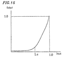
- the signal level converter 13 converts the level of the signal input thereto (i.e., the output signal from the digital filter 8 ) according to the input-output characteristic as illustrated in Figure 15 , which is obtained by normalizing the input-output sound pressure distortion characteristic illustrated in Figure 6 .
- the level-converted output signal is input to the multiplier 14 , where it is multiplied by the output signal of the coefficient update calculator 9 .
- the output signal of the coefficient update calculator 9 is multiplied by a small value which is output from the signal level converter 13 .
- the output (the calculation result) from the coefficient update calculator 9 has substantially no influence on the update operation of the coefficient of the adaptive filter 4 , so that the coefficient of the adaptive filter 4 is updated according to the output from the coefficient update calculator 6 .
- the control speaker 1 since the control speaker 1 operates in the linear region, it is possible to sufficiently control noise which contains a low frequency component (e.g., f1), as illustrated by the solid line (b) in Figure 4 .
- the coefficient of the adaptive filter 4 is updated based on the output (the calculation result) from the coefficient update calculator 9 after the multiplication operation.
- a low frequency gain of the adaptive filter 4 is suppressed so as to perform an optimal and stable noise control within the low frequency reproducibility of the control speaker 1 without inappropriately performing a control at the frequency f1, as illustrated by the solid line (b) in Figure 10 .
- Embodiments 1-3 above a structure including two coefficient update calculators has been illustrated.
- a single coefficient update calculator is used, while a low frequency band of the control signal is limited so that the adaptive filter does not generate an excessive control signal for noise having a frequency which is too low for the low band reproducibility of the control speaker, as in Embodiment 1.
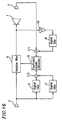
- FIG 16 is a block diagram illustrating a structure of the noise control system of this embodiment.
- the noise control system includes a control speaker 1 , an error detection microphone 2 which functions as an error detector, a noise detection microphone 3 which functions as a noise detector, an adaptive filter 4 , a digital filter 5 which approximates the propagation characteristic between the control speaker 1 and the error detection microphone 2 , a coefficient update calculator 6 , digital filters 7 and 8 each having a frequency band limiting characteristic (band limiting filters), and a phase inverter 10 for inverting the output of the adaptive filter 4 .
- the noise control system of the present embodiment further includes an adder 111 for adding the output of the digital filter 8 and the output of the error detector 2 so as to provide the sum to the coefficient update calculator 6 , and another adder 112 for adding the output of the digital filter 5 and the output of the digital filter 7 so as to provide the sum to the coefficient update calculator 6 .
- noise generated from a noise source is detected by a noise detector 3 , and a noise source signal is generated based on the detection result.
- the generated noise source signal is processed by the adaptive filter 4 , so as to output a control signal.
- a control sound is generated from the control speaker 1 based on the control signal so that the control sound interferes with the noise from the noise source, thereby reducing the noise.
- the state of interference between the control sound output from the control speaker 1 and the noise is measured by the error detector (microphone) 2 .
- the output of the error detector (microphone) 2 should ideally be zero as a result of the noise control. Therefore, the coefficient update calculator 6 performs a coefficient update calculation as previously described in Expression (1) based on a filtered X-LMS method (see Widrow and Stearns, "Adaptive Signal Processing", 1985), or the like, so as to adjust the characteristic of the adaptive filter 4 , such that the output signal of the error detector (microphone) 2 is reduced. This changes the control sound actually generated from the control speaker 1 , thereby further reducing the noise.
- the frequency characteristic of the control speaker 1 is such that the sound pressure of an output thereof is reduced in a frequency region where the frequency is less than or equal to the lower limit reproducible frequency f L , as shown in Figure 2 .
- the coefficient gain of the adaptive filter 4 sufficiently reduces (or cancels) the noise in the low frequency region while compensating for the characteristic of the control speaker 1 , thereby converging into the characteristic as illustrated in Figure 3 , where the gain has an increase in the low frequency region (a region where the frequency is less than or equal to the lower limit reproducible frequency f L of the control speaker 1 ). In such a case, a large low frequency signal is input to the control speaker 1 .
- the distortion may act as an error signal, thereby causing an adverse effect such as making the operation of the adaptive filter 4 unstable.
- the digital filters 7 and 8 are set to have a band limiting characteristic with a passband characteristic as illustrated in Figure 17 in the low frequency region where the output of the control speaker 1 is reduced (e.g., the frequency region where the frequency is less than or equal to the lower limit reproducible frequency f L of the control speaker 1 ).
- the output signal of the adaptive filter 4 is inverted by the phase inverter 10 and processed by the digital filter 8 .
- the resulting signal is added to the error detection signal by the adder 111 , and the sum is input to the coefficient update calculator 6 .
- the output signal of the noise detector 3 is processed by the digital filter 7 .
- the resulting signal is added to the output signal of the digital filter 5 by the adder 112 , and the sum is input to the coefficient update calculator 6 .
- the gain in the passband of the digital filter 7 is set to be larger than the output signal level of the digital filter 5 .
- the gain in the passband of the digital filter 8 is set to be larger than the output signal level of the error detector.
- R j (r j, r j-1, ..., r j-n-1 )
- W j (w(1) j , w(2) j , ..., w(n) j )
- S j (s j , s j-i , ..., s j-n-1 ) T .
- ⁇ W_all j denotes an output signal vector of the coefficient update calculator 6
- W j a coefficient vector of the adaptive filter 4
- R j an output vector of the digital filter 5
- S j an output signal vector of the digital filter 7
- e j an output signal of the error detector
- v j an output signal of the digital filter 8 , all at time j.
- n denotes the order of the adaptive filter 4
- ⁇ is a size parameter for a coefficient update step.
- the broken line (a) in Figure 9 is a coefficient gain of the adaptive filter 4 which is obtained by using only the output of the digital filter 5 and the output of the error detector 2 for updating the coefficient of the adaptive filter 4 .
- phase inverter 10 is connected between the adaptive filter 4 and the digital filter 8 .
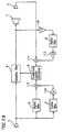
- Functions and effects similar to those described above are also obtained by the structure as illustrated in Figure 18 , where the phase inverter 10 is connected between the noise detector 3 and the digital filter 7 .
- functions and effects similar to those described above are also obtained by a structure where the phase inverter 10 is connected to the output of the digital filter 8 or the digital filter 7 .
- a coefficient controller 144 having a gain of 1/a ⁇ 1 may be provided to the output of the digital filter 5 , while providing another coefficient controller 143 having a gain of 1/b ⁇ 1 to the output signal of the error detector 2 , as illustrated in Figure 20 .
- the coefficient update calculator 6 it is possible to provide the coefficient update calculator 6 with a signal whose frequency band, in which a relatively negative coefficient update is performed, is emphasized.
- Figure 21 is a block diagram illustrating a structure of the noise control system of this embodiment. Elements in the block diagram of Figure 21 corresponding to those illustrated in the previous Embodiments with reference to, e.g., Figure 1 have like reference numerals, and will not be further described below.
- a coefficient update calculation as described above in Embodiment 1 is performed when the low frequency component of the output of the adaptive filter 4 is at a small level and the control speaker 1 is operating in the linear region.
- a coefficient update calculation which suppresses the filter gain in the low frequency region is performed when the low frequency component of the output of the adaptive filter 4 increases and the control speaker 1 enters the non-linear region. In this way, it is possible not only to sufficiently reduce the noise even in the low frequency region when the noise level is low, but also to perform a stable noise control even when the noise level in the low frequency region is high.
- the noise control system illustrated in Figure 21 includes a selector 121 for selecting one of the output of the digital filter 5 and the output of the digital filter 7 , another selector 122 for selecting one of the output of the digital filter 8 and the output of the error detector 2 , and a selection control calculator 123 for controlling the operations of the selectors 121 and 122 .
- the other elements and the functions thereof are similar to those described above in Embodiment 1.
- a low frequency component of the output signal of the adaptive filter 4 is obtained from the digital filter 8 as an output signal thereof.
- the control speaker 1 has a non-linear characteristic in the vicinity of such a low frequency
- the output sound pressure is saturated (see Figure 5 ) while the distortion increases considerably (see Figure 6 ), as illustrated in the input-output sound pressure characteristic of Figure 5 and the input-output sound pressure distortion characteristic of Figure 6 .
- noise corresponding to the broken line (a) in Figure 4
- the conventional adaptive filter 4 whose spectrum at the error detector (microphone) 2 includes signals in the vicinity of the low frequency f1, as illustrated by the broken line (a) in Figure 7
- a sufficient sound elimination cannot be realized because the control sound is saturated at the frequency f1. It may rather lead to generation of a higher harmonic wave distortion at a frequency twice or three times the frequency f1, as illustrated by a solid line (b) in Figure 7 , thereby creating new noise.
- the distortion may act as an error signal, thereby causing an adverse effect such as making the operation of the adaptive filter 4 unstable.
- the selection control calculator 123 is used to detect the output level of the low frequency component in the output from the digital filter 8 . If the output level exceeds a predetermined level Ls, the selector 122 is controlled by the selection control calculator 123 so as to select the output of the digital filter 8 . The selector 121 is controlled by the selection control calculator 123 so as to select the output of the digital filter 7 .
- the selection control calculator 123 controls the selector 121 to select the output of the digital filter 5 and the selector 122 to select the output of the error detector 2 .
- the control speaker 1 operates in the linear region when the low frequency component of the control speaker 1 is at a small level, thereby sufficiently controlling noise which contains a low frequency component (e.g., f1), as illustrated by the solid line (b) in Figure 4 .
- a low frequency component e.g., f1
- the level of the low frequency component of the adaptive filter 4 increases and the input to the control speaker 1 exceeds the threshold level Ls to enter the non-linear region, the update operation of the coefficient of the adaptive filter 4 is restricted so as to reduce the low frequency gain.
- noise control system of the present embodiment it is possible to effectively utilize the linear operability of the control speaker 1 while suppressing the operation thereof in the non-linear region, so as to provide an optimal noise control for low frequency level noise.
- one of the output of the digital filter 8 and the output of the error detector 2 is always selected by the selector 122 , while one of the output of the digital filter 5 and the output of the digital filter 7 is always selected by the selector 121 .
- each of the selectors 121 and 122 may perform a thinning-out operation on the outputs at an appropriate thinning-out frequency.
- the selector 122 may operate to transfer the output of the error detector 2 to the coefficient update calculator 6 only at one timing out of 16 transfer timings, while transferring nothing to the coefficient update calculator 6 at the other transfer timings (thus, the outputs of the error detector 2 to be transferred are thinned out), and to transfer the output of the digital filter 8 to the coefficient update calculator 6 only at one timing out of 4 transfer timings, while transferring nothing to the coefficient update calculator 6 at the other transfer timings (thus, the outputs of the digital filter 8 to be transferred are thinned out).
- the selector 121 also operates in a manner similar to that of the selector 122 regarding the selection of the outputs from the digital filters 5 and 7 . In this way, the coefficient of the adaptive filter 4 is updated in the negative direction.
- the above-described operations of the selectors 121 and 122 and the frequency of such operations may be controlled by the selection control calculator 123 .
- the digital filter is set in the low frequency region (e.g., the frequency region where the frequency is less than or equal to the lower limit reproducible frequency f L of the control speaker 1 ) in order to suppress the non-linear distortion of the control speaker 1 in the low frequency region.
- the frequency band setting of the present invention is not limited thereto, and the coefficient update operation of the adaptive filter 4 having any frequency band can be suppressed by a method similar to that described above.
- the noise detection microphone 3 For example, where external noise, which cannot be detected by the noise detection microphone 3 , is introduced into the error detection microphone 2 , the correlation between the noise detection signal and the error detection signal is reduced at the frequency of the external noise. In such a case, the noise (external noise) may not be eliminated appropriately, and the adaptive filter 4 may even malfunction to produce abnormal oscillation at the frequency of the external noise. In order to prevent this, the passband of the digital filter may be set to coincide with the frequency of the external noise.
- the noise detection signal and the adaptive filter output signal are processed by the band limiting digital filters, which have the same characteristic, so as to produce a coefficient update signal in the negative direction from both of the output signals, thereby controlling the adaptive filter used in a noise control calculation.
- the present invention prevents an undesired increase in the coefficient gain of the adaptive filter in the band of the above-described digital filter, while realizing a coefficient control of the adaptive filter used in a noise control calculation without having to use additional hardware such as an adaptive filter or an additional calculation process, thereby realizing a stable noise processing operation.
- whether or not to perform the negative coefficient update for the adaptive filter is controlled in view of the non-linear characteristic of the noise propagation system or the control sound generator.
Abstract
Description
- The present invention relates to a noise control system based on active noise control, for use in a noisy environment.
- In recent years, an active noise control system has been proposed which eliminates environmental noise, using a control sound from a loud speaker, etc. This type of a noise control system in the conventional art employs an adaptive filter for calculating a noise control signal, and may further employ an auxiliary adaptive filter for preventing an increase in the gain of the adaptive filter, as disclosed in, for example, Japanese Laid-Open Publication No. 5-67948.
- Figure 22 is a block diagram illustrating a structure of such a conventional noise control system. Referring to Figure 22, the noise control system includes a
control speaker 1, anerror detection microphone 2 which functions as an error detector, anoise detection microphone 3 which functions as a noise detector,adaptive filters 4 and 15, adigital filter 5 which approximates the propagation characteristic between thecontrol speaker 1 and theerror detection microphone 2,coefficient update calculators digital filter 7 having a frequency band limiting characteristic. - With the structure illustrated in Figure 22, noise generated from a noise source is detected by the
noise detector 3, and a noise source signal is generated based on the detection result. The generated noise source signal is processed by the adaptive filter 4, so as to output a control signal. A control sound is generated from thecontrol speaker 1 based on the control signal so that the control sound interferes with the noise from the noise source, thereby reducing the noise. - Moreover, the state of interference between the control sound output from the
control speaker 1 and the noise is measured by the error detector (microphone) 2. The output of the error detector (microphone) 2 should ideally be zero as a result of the noise control. Therefore, thecoefficient update calculator 6 performs a calculation such that the output signal of the error detector (microphone) 2 is reduced, and controls the coefficient of the adaptive filter 4 based on the calculation result. - On the other hand, the
coefficient update calculator 9 performs a calculation such that the output of theadaptive filter 15 is reduced, and controls the coefficient of theadaptive filter 15 based on the calculation result. A band limiting signal produced by thedigital filter 7 is input to theadaptive filter 15, and the coefficient of theadaptive filter 15 converges into a value which suppresses signals in the band. The coefficients of theadaptive filters 4 and 15 can be shared by each other so as to combine the effects of the twocoefficient update calculators digital filter 7. - Figure 23 is a block diagram illustrating a structure of another conventional noise control system as disclosed in Japanese Laid-Open Publication No. 7-271383. Referring to Figure 23, the noise control system includes a
control speaker 1, anerror detection microphone 2 which functions as an error detector, anoise detection microphone 3 which functions as a noise detector, an adaptive filter 4, adigital filter 5 which approximates the propagation characteristic between thecontrol speaker 1 and theerror detection microphone 2,coefficient update calculators digital filters switch section 32. - With the structure illustrated in Figure 23, noise generated from a noise source is detected by the
noise detector 3, and a noise source signal is generated based on the detection result. The generated noise source signal is processed by the adaptive filter 4, so as to output a control signal. A control mound is generated from thecontrol speaker 1 based on the control signal so that the control sound interferes with the noise from the noise source, thereby reducing the noise. - Moreover, the state, of interference between the control sound output from the
control speaker 1 and the noise is measured by the error detector (microphone) 2. The output of the error detector (microphone) 2 should ideally be zero as a result of the noise control. Therefore, thecoefficient update calculator 6 performs a calculation such that the output signal of the error detector (microphone) 2 is reduced. A band limiting signal produced by thedigital filter 7 and another band limiting signal produced by thedigital filter 8 are input to thecoefficient update calculator 9, and thecoefficient update calculator 9 performs a coefficient update calculation such that the adaptive filter 4 suppresses the output of the signal in the band. Theswitch section 32 switches between the outputs of thecoefficient update calculators digital filters - However, the conventional noise control system as illustrated in Figure 22 requires the auxiliary
adaptive filter 15 for controlling the update operation of the coefficient of the adaptive filter 4, thereby increasing the amount of calculation to be performed. - The other conventional noise control system as illustrated in Figure 23 requires two
coefficient update calculators coefficient update calculators switch section 32, coefficient update operations of the adaptive filter by thecoefficient update calculators - A noise control system of the present invention includes: a control sound generator for generating a control sound; an error detector for detecting an error signal between the control sound and noise; a noise detector for detecting a noise source signal; an adaptive filter for outputting a control signal; and a coefficient updator for updating a coefficient of the adaptive filter, the coefficient updator comprising at least a first digital filter, a first coefficient update calculator, a second digital filter, a phase inverter, a third digital filter, and a second coefficient update calculator. The coefficient updator has a function of suppressing an increase in a coefficient gain of the adaptive filter in a predetermined frequency band.
- In one embodiment, the coefficient updator is such that: the first digital filter receives, as an input thereto, an output of the noise detector; the first coefficient update calculator receives, as inputs thereto, an output of the first digital filter and an output of the error detector; the phase inverter inverts the output of the noise detector; the second digital filter receives, as an input thereto, an output of the phase inverter; the third digital filter receives, as an input thereto, the output of the error detector; the second coefficient update calculator receives, as inputs thereto, outputs of the second and third digital filters; the first digital filter approximates a propagation characteristic between the control sound generator and the error detector; the second and third digital filters have a common passband frequency characteristic; the first coefficient update calculator performs a calculation such that the output of the error detector is reduced, and updates the coefficient of the adaptive filter based on the calculation result; and the second coefficient update calculator performs a calculation such that the output of the third digital filter is reduced, and updates the coefficient of the adaptive filter based on the output of the coefficient update calculator.
- In another embodiment, the coefficient updator is such that: the first digital filter receives, as an input thereto, an output of the noise detector; the first coefficient update calculator receives, as inputs thereto, an output of the first digital filter and an output of the error detector; the second digital filter receives, as an input thereto, an output of the noise detector; the third digital filter receives, as an input thereto, the output of the error detector; the second coefficient update calculator receives, as inputs thereto, outputs of the second and third digital filters; the phase inverter inverts an output of the second coefficient update calculator; the first digital filter approximates a propagation characteristic between the control sound generator and the error detector; the second and third digital filters have a common passband frequency characteristic; the first coefficient update calculator performs a calculation such that the output of the error detector is reduced, and updates the coefficient of the adaptive filter based on the calculation result; and the second coefficient update calculator performs a calculation such that the output of the third digital filter is reduced, inverts and outputs the calculation result, and updates the coefficient of the adaptive filter based on the output of the second coefficient update calculator.
- In still another embodiment, the coefficient updator further includes: a first selection controller for thinning out the outputs of the first coefficient update calculator; a second selection controller for thinning out the outputs of the second coefficient update calculator; and a selection control calculator for receiving an output signal of the third digital filter to control the first and second selection controllers; the first digital filter receives, as an input thereto, an output of the noise detector; the first coefficient update calculator receives, as inputs thereto, an output of the first digital filter and an output of the error detector; the phase inverter inverts an output of the adaptive filter; the third digital filter receives, as an input thereto, an output of the phase inverter; the second coefficient update calculator receives, as inputs thereto, outputs of the second and third digital filters; the first digital filter approximates a propagation characteristic between the control sound generator and the error detector; the second and third digital filters have a common passband frequency characteristic; the first coefficient update calculator performs a calculation such that the output of the error detector is reduced; the second coefficient update calculator performs a calculation such that the output of the third digital filter is reduced; and when a level of the output signal of the third digital filter exceeds a predetermined value, the selection control calculator updates the coefficient of the adaptive filter by controlling the first and second selection controllers so that the first selection controller performs the thinning-out operation at a thinning-out frequency lower than that of the second selection controller.
- In still another embodiment, the coefficient updator further includes a a first selection controller for switching between selecting an output of the first coefficient update calculator and selecting nothing; a second selection controller for switching between selecting an output of the second coefficient update calculator and selecting nothing; and a selection control calculator for receiving an output signal of the third digital filter to control the first and second selection controllers; the first digital filter receives, as an input thereto, an output of the noise detector; the first coefficient update calculator receives, as inputs thereto, an output of the first digital filter and an output of the error detector; the phase inverter inverts an output of the adaptive filter; the third digital filter receives, as an input thereto, an output of the phase inverter; the second coefficient update calculator receives, as inputs thereto, outputs of the second and third digital filters; the first digital filter approximates a propagation characteristic between the control sound generator and the error detector; the second and third digital filters have a common passband frequency characteristic; the first coefficient update calculator performs a calculation such that the output of the error detector is reduced; the second coefficient update calculator performs a calculation such that the output of the third digital filter is reduced; and when a level of the output signal of the third digital filter exceeds a predetermined value, the selection control calculator updates the coefficient of the adaptive filter by controlling the first and second selection controllers so that the first selection controller is switched to select nothing at a switching operation frequency lower than that at which the second selection controller is switched to select nothing.
- In still another embodiment, the coefficient updator further includes: a signal level converter for receiving an output signal of the third digital filter to convert a level of the signal; and a multiplier for multiplying an output of the signal level converter by an output of the second coefficient update calculator so as to update the coefficient of the adaptive filter; the first digital filter receives, as an input thereto, an output of the noise detector; the first coefficient update calculator receives, as inputs thereto, an output of the first digital filter and an output of the error detector; the second digital filter receives, as an input thereto, the output of the noise detector; the phase inverter inverts an output of the adaptive filter; the third digital filter receives, as an input thereto, an output of the phase inverter; the second coefficient update calculator receives, as inputs thereto, outputs of the second and third digital filters; the first digital filter approximates a propagation characteristic between the control sound generator and the error detector; the second and third digital filters have a common passband frequency characteristic; the first coefficient update calculator performs a calculation such that the output of the error detector is reduced; the second coefficient update calculator performs a calculation such that the output of the third digital filter is reduced; and the signal level converter has an input-output characteristic which is approximated to a characteristic obtained by normalizing an input-distortion characteristic of the control sound generator.
- In each of the above-described configurations, the predetermined frequency band may exist in a low frequency region.
- For example, the predetermined frequency band may be a frequency region where the frequency is less than or equal to a lower limit reproducible frequency of the control sound generator.
- Another noise control system of the present invention includes: a control sound generator for generating a control sound; an error detector for detecting an error signal between the control sound and noise; a noise detector for detecting a noise source signal; an adaptive filter for outputting a control signal; and a coefficient updator for updating a coefficient of the adaptive filter, the coefficient updator comprising at least a first digital filter, a second digital filter, a third digital filter, a coefficient update calculator, a phase inverter, a first adder, and a second adder. The coefficient updator has a function of suppressing an increase in a coefficient gain of the adaptive filter in a predetermined frequency band.
- In one embodiment, the coefficient updator is such that: the first digital filter receives, as an input thereto, an output of the noise detector; the second digital filter receives, as an input thereto, the output of the noise detector; the first adder receives, as inputs thereto, an output of the first digital filter and an output of the second digital filter; the second adder receives, as inputs thereto, an output of the error detector and an output of the third digital filter; the coefficient update calculator receives, as inputs thereto, an output of the first adder and an output of the second adder; the phase inverter inverts an output of the adaptive filter; the third digital filter receives, as an input thereto, the output of the phase inverter; the first digital filter approximates a propagation characteristic between the control sound generator and the error detector; the second and third digital filters have a common passband frequency characteristic; and the coefficient update calculator performs a calculation such that the output of the second adder is reduced, and updates the coefficient of the adaptive filter based on the calculation result.
- In another embodiment, the coefficient updator is such that: the first digital filter receives, as an input thereto, an output of the noise detector; the phase inverter inverts the output of the noise detector: the second digital filter receives, as an input thereto, the output of the phase inverter; the first adder receives, as inputs thereto, an output of the first digital filter and an output of the second digital filter; the second adder receives, as inputs thereto, an output of the error detector and an output of the third digital filter; the coefficient update calculator receives, as inputs thereto, an output of the first adder and an output of the second adder; the third digital filter receives, as an input thereto, an output of the adaptive filter; the first digital filter approximates a propagation characteristic between the control sound generator and the error detector; the second and third digital filters have a common passband frequency characteristic; and the coefficient update calculator performs a calculation such that the output of the second adder is reduced, and updates the coefficient of the adaptive filter based on the calculation result.
- In still another embodiment, the coefficient updator further includes: a first coefficient controller for multiplying an output of the second digital filter by a first coefficient factor; and a second coefficient controller for multiplying an output of the third digital filter by a second coefficient factor; the first digital filter receives, as an input thereto, an output of the noise detector; the second digital filter receives, as an input thereto, the output of the noise detector; the first adder receives, as inputs thereto, an output of the first digital filter and an output of the first coefficient controller; the second adder receives, as inputs thereto, an output of the error detector and an output of the second coefficient controller; the coefficient update calculator receives, as inputs thereto, an output of the first adder and an output of the second adder; the phase inverter inverts an output of the adaptive filter; the third digital filter receives, as an input thereto, the output of the phase inverter; each of the first coefficient factor and the second coefficient factor is set to be equal to or more than 1; the first digital filter approximates a propagation characteristic between the control sound generator and the error detector; the second and third digital filters have a common passband frequency characteristic; and the coefficient update calculator performs a calculation such that the output of the second adder is reduced, and updates the coefficient of the adaptive filter based on the calculation result.
- For example, the first coefficient controller may be set so that in a passband of the second digital filter, the output of the first coefficient controller is larger than an output signal of the first digital filter. Alternatively, the second coefficient controller may be set so that in a passband of the third digital filter, the output of the second coefficient controller is larger than an output signal of the error detector.
- In one embodiment, the coefficient updator further includes: a first coefficient controller for multiplying an output of the first digital filter by a first coefficient factor; and a second coefficient controller for multiplying an output of the error detector by a second coefficient factor; the first digital filter receives, as an input thereto, an output of the noise detector; the second digital filter receives, as an input thereto, the output of the noise detector; the first adder receives, as inputs thereto, an output of the first coefficient controller and an output of the second digital filter; the second adder receives, as inputs thereto, an output of the second coefficient controller and an output of the third digital filter; the coefficient update calculator receives, as inputs thereto, an output of the first adder and an output of the second adder; the phase inverter inverts an output of the adaptive filter; the third digital filter receives, as an input thereto, the output of the phase inverter; each of the first coefficient factor and the second coefficient factor is set to be less than or equal to 1; the first digital filter approximates a propagation characteristic between the control sound generator and the error detector; the second and third digital filters have a common passband frequency characteristic; and the coefficient update calculator performs a calculation such that the output of the second adder is reduced, and updates the coefficient of the adaptive filter based on the calculation result.
- For example, the first coefficient controller may be set so that in a passband of the second digital filter, the output of the first coefficient controller is smaller than an output signal of the first digital filter. Alternatively, the second coefficient controller may be set so that in a passband of the third digital filter, the output of the second coefficient controller is smaller than an output signal of the error detector.
- In each of the above-described configurations, the predetermined frequency band may exist in a low frequency region.
- For example, the predetermined frequency band may be a frequency region where the frequency is less than or equal to a lower limit reproducible frequency of the control sound generator.
- The predetermined frequency band may exist in a frequency region where there is a correlation between an output signal of the noise detector and an output signal of the error detector.
- With the noise control system of the present invention having the features as described above, the noise detection signal and the adaptive filter output signal are processed by the band limiting digital filters, which have the same characteristic, so as to produce a coefficient update signal in the negative direction from both of the output signal, thereby controlling the adaptive filter used in a noise control calculation. In this way, the present invention prevents an undesired increase in the coefficient gain of the adaptive filter in the band of the above-described digital filter, while realizing a coefficient control of the adaptive filter used in a noise control calculation without having to use additional hardware such as an adaptive filter or an additional calculation process, thereby realizing a stable noise processing operation.
- Moreover, the update frequency, at which the negative coefficient update for the adaptive filter is performed, is controlled in view of the non-linear characteristic of the noise propagation system or the control sound generator, whereby it is possible to realize a noise control with no band limitation when the noise signal is small.
- Thus, the invention described herein makes possible the advantage of providing a noise control system capable of a stable noise processing operation by controlling the coefficient of an adaptive filter used in noise control calculations without having to provide additional hardware such as an adaptive filter or an additional calculation process.
- This and other advantages of the present invention will become apparent to those skilled in the art upon reading and understanding the following detailed description with reference to the accompanying figures.
-
- Figure 1 is a block diagram illustrating a structure
of a noise control system according to
Embodiment 1 of the present invention; - Figure 2 illustrates a sound pressure-frequency characteristic of a control speaker which may be included in the structure of the present invention;
- Figure 3 illustrates a gain-frequency
characteristic of an adaptive filter which is obtained by
using only the
coefficient update calculator 6 which is included in the structure of the present invention; - Figure 4 illustrates a noise control characteristic while the control speaker is in a linear region;
- Figure 5 illustrates an input-output characteristic of the control speaker which may be included in the structure of the present invention;
- Figure 6 illustrates an input-sound pressure distortion characteristic of the control speaker which may be included in the structure of the present invention;
- Figure 7 illustrates a noise control characteristic while the control speaker is in a non-linear region;
- Figure 8 illustrates a gain-frequency
characteristic of
digital filters - Figure 9 illustrates a gain-frequency characteristic of the adaptive filter which is obtained by using the entire structure of the present invention;
- Figure 10 illustrates a noise control characteristic obtained by the structure of the present invention;
- Figure 11 is a block diagram illustrating a
structure of a modified noise control system according to
Embodiment 1 of the present invention; - Figure 12 is a block diagram illustrating a
structure of another modified noise control system according
to
Embodiment 1 of the present invention; - Figure 13 is a block diagram illustrating a
structure of a noise control system according to
Embodiment 2 of the present invention; - Figure 14 is a block diagram illustrating a
structure of a noise control system according to
Embodiment 3 of the present invention; - Figure 15 illustrates an input-output characteristic of a signal level converter which is included in the structure illustrated in Figure 14;
- Figure 16 is a block diagram illustrating a structure of a noise control system according to Embodiment 4 of the present invention;
- Figure 17 illustrates a gain-frequency characteristic
of the
digital filters - Figure 18 is a block diagram illustrating a structure of a modified noise control system according to Embodiment 4 of the present invention;
- Figure 19 is a block diagram illustrating a structure of another modified noise control system according to Embodiment 4 of the present invention;
- Figure 20 is a block diagram illustrating a structure of still another modified noise control system according to Embodiment 4 of the present invention;
- Figure 21 is a block diagram illustrating a
structure of a noise control system according to
Embodiment 5 of the present invention; - Figure 22 is a block diagram illustrating a structure of a conventional noise control system; and
- Figure 23 is a block diagram illustrating a structure of another conventional noise control system.
-
- A noise control system according to
Embodiment 1 of the present invention will be described below with reference to the accompanying figures. - In the present embodiment, a low frequency band of the control signal is limited so that the adaptive filter does not generate an excessive control signal for noise having a frequency which is too low for the low band reproducibility of the control speaker.
- Figure 1 is a block diagram illustrating a structure of the noise control system of this embodiment. Referring to Figure 1, the noise control system includes a
control speaker 1, anerror detection microphone 2 which functions as an error detector, anoise detection microphone 3 which functions as a noise detector, an adaptive filter 4, adigital filter 5 which approximates the propagation characteristic between thecontrol speaker 1 and theerror detection microphone 2,coefficient update calculators digital filters phase inverter 10 for inverting the output of the adaptive filter 4. - With the structure illustrated in Figure 1, noise generated from a noise source is detected by a
noise detector 3, and a noise source signal is generated based on the detection result. The generated noise source signal is processed by the adaptive filter 4, so as to output a control signal. A control sound is generated from thecontrol speaker 1 based on the control signal so that the control sound interferes with the noise from the noise source, thereby reducing the noise. - Moreover, the state of interference between the control sound output from the
control speaker 1 and the noise is measured by the error detector (microphone) 2. The output of the error detector (microphone) 2 should ideally be zero as a result of the noise control. Therefore, thecoefficient update calculator 6 performs a coefficient update calculation as shown in Expression (1) later based on a filtered X-LMS method (see Widrow and Stearns, "Adaptive Signal Processing", 1985), or the like, so as to adjust the characteristic of the adaptive filter 4, such that the output signal of the error detector (microphone) 2 is reduced. This changes the control sound actually generated from thecontrol speaker 1, thereby further reducing the noise. - Typically, the frequency characteristic of the
control speaker 1 is such that the sound pressure of an output thereof is reduced in a frequency region where the frequency is less than or equal to the lower limit reproducible frequency fL, as shown in Figure 2. For example, in the case where noise has a spectrum which includes such a low frequency region, if only thecoefficient update calculator 6 is used for updating the coefficient of the adaptive filter 4, the coefficient gain of the adaptive filter 4 is required to sufficiently reduce (or cancel) the noise in the low frequency region while compensating for the characteristic of thecontrol speaker 1, thereby converging into the characteristic as illustrated in Figure 3, where the gain has an increase in the low frequency region (a region where the frequency is less than or equal to the lower limit reproducible frequency fL of the control speaker 1). In such a case, a large low frequency signal is input to thecontrol speaker 1. - In a region where the linearity of the control speaker is maintained, even if the noise spectrum at the error detector (microphone) 2 includes signals in the vicinity of a low frequency f1 as illustrated by a broken line (a) in Figure 4, the peak of the noise level is cut down, as illustrated by a solid line (b) in Figure 4, thereby realizing an appropriate sound eliminating operation.
- However, where the
control speaker 1 has a nonlinear characteristic in the vicinity of such a low frequency, if the input level exceeds a threshold level Ls, the output sound pressure is saturated (see Figure 5) while the distortion increases considerably (see Figure 6), as illustrated in the input-output sound pressure characteristic of Figure 5 and the input-output sound pressure distortion characteristic of Figure 6. In such a case, if noise (corresponding to the broken line (a) in Figure 4) whose spectrum at the error detector (microphone) 2 includes signals in the vicinity of the low frequency f1, as illustrated by the broken line (a) in Figure 7, is processed with the conventional adaptive filter 4, a sufficient sound elimination cannot be realized because the control sound is saturated at the frequency f1. It may rather lead to generation of a higher harmonic wave distortion at a frequency twice or three times the frequency f1, as illustrated by a solid line (b) in Figure 7, thereby creating new noise. The distortion may act as an error signal, thereby causing an adverse effect such as making the operation of the adaptive filter 4 unstable. - In view of this, in the present embodiment, the
digital filters control speaker 1 is reduced (e.g., the frequency region where the frequency is less than or equal to the lower limit reproducible frequency fL of the control speaker 1). Under such a setting, the output signal of the adaptive filter 4 is inverted by thephase inverter 10 and processed by thedigital filter 8 so as to obtain an error signal, while processing the output signal of thenoise detector 3 by thedigital filter 7 and inputting the processed signal as a reference signal to thecoefficient update calculator 9. Thecoefficient update calculator 9 performs a calculation according to Expression (2) to be described later, using an algorithm similar to that of thecoefficient update calculator 6. Then, the coefficient of the adaptive filter 4 is updated by both of thecoefficient update calculators - With the above-described structure, the
coefficient update calculator 9 operates so as to reduce the output signal of thedigital filter 7, whereby the increase in the coefficient gain of the adaptive filter 4 is suppressed in the low frequency region as illustrated by the solid line (b) in Figure 9. A broken line (a) in Figure 9 is a coefficient gain of the adaptive filter 4 which is obtained by using only thecoefficient update calculator 6, illustrated in Figure 3 for updating the coefficient of the adaptive filter 4. - As a result of the above-described suppression of the increase in the coefficient gain in the low frequency region, an excessive low frequency signal is prevented from being input to the
control speaker 1, thereby performing a stable noise control within the low frequency reproducibility of thecontrol speaker 1 without inappropriately performing a control at the frequency f1, as illustrated by a solid line (b) in Figure 10. A broken line (a) in Figure 10 corresponds to the broken line (a) in Figures 4 and 7. - Moreover, as compared to the conventional structure described above with reference to Figure 22, where an auxiliary adaptive filter is used, the amount of hardware to be used and the amount of calculation to be performed are reduced with the structure illustrated in Figure 1.
- Expressions (1)-(3) used in the above description are as follows:
- In these expressions, ΔWj denotes an output signal vector of the
coefficient update calculator 6, ΔUj an output signal vector of thecoefficient update calculator 9, Wj a coefficient vector of the adaptive filter 4, Rj an output vector of thedigital filter 5, Sj an output signal vector of thedigital filter 7, ej an output signal of the error detector, and vj an output signal of thedigital filter 8, all at time j. Moreover, it denotes the order of the adaptive filter 4, and µ and ν are size parameters for a coefficient update step. - In the above description, the
phase inverter 10 is connected between the adaptive filter 4 and thedigital filter 8. Functions and effects similar to those described above are also obtained by the structure as illustrated in Figure 11, where thephase inverter 10 is connected between thenoise detector 3 and thedigital filter 7. Moreover, functions and effects similar to those described above are also obtained by the structure as illustrated in Figure 12, where thephase inverter 10 is connected to the output of thecoefficient update calculator 9, or by another structure where thephase inverter 10 is connected to the output of thedigital filter 8 or thedigital filter 7. Elements in the block diagrams of Figures 11 and 12 corresponding to those shown in Figure 1 have like reference numerals, and will not be further described here. - A noise control system according to
Embodiment 2 of the present invention will be described with reference to Figure 13. - Figure 13 is a block diagram illustrating a structure of the noise control system of this embodiment. Elements in the block diagram of Figure 13 corresponding to those illustrated in
Embodiment 1 with reference to, e.g., Figure 1 have like reference numerals, and will not be further described below. - According to the present embodiment, the update frequency at which the coefficient update calculation is performed by the
coefficient update calculator 6 is increased while the low frequency component of the output of the adaptive filter 4 is small and thecontrol speaker 1 is operating in the linear region. On the other hand, the update frequency at which the coefficient update calculation is performed by thecoefficient update calculator 9 is increased, when the law frequency component of the output of the adaptive filter 4 increases and thecontrol speaker 1 enters the non-linear region, so as to perform a coefficient update calculation which suppresses the filter gain in the low frequency region. In this way, it is possible not only to sufficiently reduce the noise even in the low frequency region when the noise level is low, but also to perform a stable noise control even when the noise level in the low frequency region is high. - Referring to Figure 13, the illustrated noise control system includes a
selector 12 for thinning out the outputs of thecoefficient update calculator 6, anotherselector 22 for thinning out the outputs of thecoefficient update calculator 9, and aselection control calculator 11 for controlling the operations of theselectors Embodiment 1. As illustrated in Figure 13, theselectors coefficient update calculators selectors coefficient update calculators coefficient update calculators - In order to update the coefficient of the adaptive filter 4, a large amount of calculation is required. In the structure illustrated in Figure 13, not all of the calculation is performed for each occurrence of a sampling operation. Instead, a thinned-out update calculation is employed where a coefficient update operation is performed by each of the
selectors selectors selection control calculator 11. - For example, while the low frequency component of the output of the adaptive filter 4 is at a small level and the
control speaker 1 is operating in the linear region, theselector 12 is closed once for 4 sampling operations to control the adaptive filter by the output of thecoefficient update calculator 6; and theselector 22 is closed once for 16 sampling operations to control the adaptive filter by the output of thecoefficient update calculator 9. Thus, the noise control operation is performed by setting the thinning-out frequency of theselector 22 to be lower than that of theselector 12. - In the structure as illustrated in Figure 13, a low frequency component of the output signal of the adaptive filter 4 is obtained from the
digital filter 8 as an output signal thereof. As described above inEmbodiment 1, in the case where thecontrol speaker 1 has a non-linear characteristic in the vicinity of such a low frequency, if the input level exceeds a threshold level Ls, the output sound pressure is saturated (see Figure 5) while the distortion increases considerably (see Figure 6), as illustrated in the input-output sound pressure characteristic of Figure 5 and the input-output sound pressure distortion characteristic of Figure 6. In such a case, if noise (corresponding to the broken line (a) in Figure 4) whose spectrum at the error detector (microphone) 2 includes signals in the vicinity of the low frequency f1, as illustrated by the broken line (a) in Figure 7, is processed with the conventional adaptive filter 4, a sufficient sound elimination cannot be realized because the control mound is saturated at the frequency f1. It may rather lead to generation of a higher harmonic wave distortion at a frequency twice or three times the frequency f1, as illustrated by a solid line (b) in Figure 7, thereby creating new noise. The distortion may act as an error signal, thereby causing an adverse effect such as making the operation of the adaptive filter 4 unstable. - In view of this, in the present embodiment, the output level of a low frequency component of the output from the
digital filter 8 is detected by theselection control calculator 11 and, if the output level exceeds Ls, the thinning-out frequencies of theselectors selector 22 is larger than that of theselector 12. For example, theselector 12 is closed once for 16 sampling operations so as to use the output of thecoefficient update calculator 6 for updating the coefficient of the adaptive filter 4 only at this timing, thus controlling the adaptive filter 4 while thinning out the outputs of thecoefficient update calculator 6. On the other hand, theselector 22 is closed once for 4 sampling operations so as to use the output of thecoefficient update calculator 9 for updating the coefficient of the adaptive filter 4 only at this timing, thus controlling the adaptive filter 4 while thinning out the outputs of thecoefficient update calculator 9. As a result, the coefficient of the adaptive filter 4 is updated based on an output of thecoefficient update calculator 9 more often than based on an output of thecoefficient update calculator 6. - With the above-described structure, the
control speaker 1 operates in the linear region when the low frequency component of thecontrol speaker 1 is at a small level, thereby sufficiently controlling noise which contains a low frequency component (e.g., f1), as illustrated by the solid line (b) in Figure 4. On the other hand, when the level of the low frequency component of the adaptive filter 4 increases and the input to thecontrol speaker 1 exceeds the threshold level Ls to enter the non-linear region, the update operation of the coefficient of the adaptive filter 4 is restricted so as to reduce the low frequency gain. As a result, it is possible to stably control noise without generating a distortion, as illustrated by the solid line (b) in Figure 10. - Thus, with the noise control system of the present embodiment, it is possible to effectively utilize the linear operability of the
control speaker 1 while suppressing the operation thereof in the non-linear region, so as to provide an optimal noise control for low frequency level noise. - A noise control system according to
Embodiment 3 of the present invention will be described with reference to Figures 14 and 15. - Figure 14 is a block diagram illustrating the noise control system of this embodiment. Elements in the block diagram of Figure 14 corresponding to those illustrated in
Embodiment 1 with reference to, e.g., Figure 1 have like reference numerals, and will not be further described below. - According to the present embodiment, the coefficient of the adaptive filter 4 is updated in an optimal manner according to the level of low frequency noise, in view of the output level of the adaptive filter 4 and the linearity of the
control speaker 1. In this way, it is possible not only to sufficiently reduce the noise even in the low frequency region when the noise level is low, but also to perform a stable noise control even when the noise level in the low frequency region is high. - Referring to Figure 14, the illustrated noise control system includes a
signal level converter 13 for receiving a signal output from thedigital filter 8 as an input. The output signal from thesignal level converter 13 is multiplied by the output from thecoefficient update calculator 9 at amultiplier 14 which is provided between thecoefficient update calculator 9 and the adaptive filter 4. The other elements and the functions thereof are similar to those described above inEmbodiment 1. - In the structure as illustrated in Figure 14, a low frequency component of the output signal of the adaptive filter 4 is obtained from the
digital filter 8 as an output signal thereof. As described above inEmbodiment 1, in the case where thecontrol speaker 1 has a non-linear characteristic in the vicinity of such a low frequency, if the input level exceeds a threshold level Ls, the output sound pressure is saturated (see Figure 5) while the distortion increases considerably (see Figure 6), as illustrated in the input-output sound pressure characteristic of Figure 5 and the input-output sound pressure distortion characteristic of Figure 6. In such a case, if noise (corresponding to the broken line (a) in Figure 4) whose spectrum at the error detector (microphone) 2 includes signals in the vicinity of the low frequency f1, as illustrated by the broken line (a) in Figure 7, is processed with the conventional adaptive filter 4, a sufficient sound elimination cannot be realized because the control sound is saturated at the frequency f1. It may rather lead to generation of a higher harmonic wave distortion at a frequency twice or three times the frequency f1, as illustrated by a solid line (b) in Figure 7, thereby creating new noise. The distortion may act as an error signal, thereby causing an adverse effect such as making the operation of the adaptive filter 4 unstable. - In view of this, in the present embodiment, the
signal level converter 13 detects the level of the output signal from thedigital filter 8, and performs a conversion operation for the detected signal level. In particular, thesignal level converter 13 converts the level of the signal input thereto (i.e., the output signal from the digital filter 8) according to the input-output characteristic as illustrated in Figure 15, which is obtained by normalizing the input-output sound pressure distortion characteristic illustrated in Figure 6. Then, the level-converted output signal is input to themultiplier 14, where it is multiplied by the output signal of thecoefficient update calculator 9. As a result, the coefficient of the adaptive filter 4 is updated according to Expression (4) below:signal level converter 13 as illustrated in Figure 15. - With such a structure, in a region where the
control speaker 1 operates linearly and the distortion thereof is small, the output signal of thecoefficient update calculator 9 is multiplied by a small value which is output from thesignal level converter 13. Thus, the output (the calculation result) from thecoefficient update calculator 9 has substantially no influence on the update operation of the coefficient of the adaptive filter 4, so that the coefficient of the adaptive filter 4 is updated according to the output from thecoefficient update calculator 6. Moreover, since thecontrol speaker 1 operates in the linear region, it is possible to sufficiently control noise which contains a low frequency component (e.g., f1), as illustrated by the solid line (b) in Figure 4. - On the other hand, when the level of the low frequency component of the adaptive filter 4 increases and the input to the
control speaker 1 exceeds the threshold level Ls to enter the non-linear region, the distortion thereof increases. In such a case, a multiplier factor is set by thesignal level converter 13 according to the level of the low frequency output from thecontrol speaker 1, and the output signal of thecoefficient update calculator 9 is multiplied by the multiplier factor. As a result, the coefficient of the adaptive filter 4 is updated based on the output (the calculation result) from thecoefficient update calculator 9 after the multiplication operation. Thus, a low frequency gain of the adaptive filter 4 is suppressed so as to perform an optimal and stable noise control within the low frequency reproducibility of thecontrol speaker 1 without inappropriately performing a control at the frequency f1, as illustrated by the solid line (b) in Figure 10. - A noise control system according to Embodiment 4 of the present invention will be described with reference to the figures.
- In Embodiments 1-3 above, a structure including two coefficient update calculators has been illustrated. In this embodiment, a single coefficient update calculator is used, while a low frequency band of the control signal is limited so that the adaptive filter does not generate an excessive control signal for noise having a frequency which is too low for the low band reproducibility of the control speaker, as in
Embodiment 1. - Figure 16 is a block diagram illustrating a structure of the noise control system of this embodiment. Referring to Figure 16, the noise control system includes a
control speaker 1, anerror detection microphone 2 which functions as an error detector, anoise detection microphone 3 which functions as a noise detector, an adaptive filter 4, adigital filter 5 which approximates the propagation characteristic between thecontrol speaker 1 and theerror detection microphone 2, acoefficient update calculator 6,digital filters phase inverter 10 for inverting the output of the adaptive filter 4. The noise control system of the present embodiment further includes anadder 111 for adding the output of thedigital filter 8 and the output of theerror detector 2 so as to provide the sum to thecoefficient update calculator 6, and anotheradder 112 for adding the output of thedigital filter 5 and the output of thedigital filter 7 so as to provide the sum to thecoefficient update calculator 6. - With the structure illustrated in Figure 16, noise generated from a noise source is detected by a
noise detector 3, and a noise source signal is generated based on the detection result. The generated noise source signal is processed by the adaptive filter 4, so as to output a control signal. A control sound is generated from thecontrol speaker 1 based on the control signal so that the control sound interferes with the noise from the noise source, thereby reducing the noise. - Moreover, the state of interference between the control sound output from the
control speaker 1 and the noise is measured by the error detector (microphone) 2. The output of the error detector (microphone) 2 should ideally be zero as a result of the noise control. Therefore, thecoefficient update calculator 6 performs a coefficient update calculation as previously described in Expression (1) based on a filtered X-LMS method (see Widrow and Stearns, "Adaptive Signal Processing", 1985), or the like, so as to adjust the characteristic of the adaptive filter 4, such that the output signal of the error detector (microphone) 2 is reduced. This changes the control sound actually generated from thecontrol speaker 1, thereby further reducing the noise. - Typically, the frequency characteristic of the
control speaker 1 is such that the sound pressure of an output thereof is reduced in a frequency region where the frequency is less than or equal to the lower limit reproducible frequency fL, as shown in Figure 2. For example, where noise has a spectrum which includes such a low frequency region, if only thecoefficient update calculator 6 is used for updating the coefficient of the adaptive filter 4, the coefficient gain of the adaptive filter 4 sufficiently reduces (or cancels) the noise in the low frequency region while compensating for the characteristic of thecontrol speaker 1, thereby converging into the characteristic as illustrated in Figure 3, where the gain has an increase in the low frequency region (a region where the frequency is less than or equal to the lower limit reproducible frequency fL of the control speaker 1). In such a case, a large low frequency signal is input to thecontrol speaker 1. - In a region where the linearity of the control speaker is maintained, even if the noise spectrum at the error detector (microphone) 2 includes signals in the vicinity of a low frequency f1 as illustrated by the broken line (a) in Figure 4, the peak of the noise level is cut down, as illustrated by the solid line (b) in Figure 4, thereby realizing an appropriate sound eliminating operation.
- However, where the
control speaker 1 has a nonlinear characteristic in the vicinity of such a low frequency, if the input level exceeds a threshold level Ls, the output sound pressure is saturated (see Figure 5) while the distortion increases considerably (see Figure 6), as illustrated in the input-output sound pressure characteristic of Figure 5 and the input-output sound pressure distortion characteristic of Figure 6. In such a case, if noise (corresponding to the broken line (a) in Figure 4) whose spectrum at the error detector (microphone) 2 includes signals in the vicinity of the low frequency f1, as illustrated by the broken line (a) in Figure 7, is processed with the conventional adaptive filter 4, a sufficient sound elimination cannot be realized because the control sound is saturated at the frequency f1. It may rather lead to generation of a higher harmonic wave distortion at a frequency twice or three times the frequency f1, as illustrated by the solid line (b) in Figure 7, thereby creating new noise. The distortion may act as an error signal, thereby causing an adverse effect such as making the operation of the adaptive filter 4 unstable. - In view of this, in the present embodiment, the
digital filters control speaker 1 is reduced (e.g., the frequency region where the frequency is less than or equal to the lower limit reproducible frequency fL of the control speaker 1). Under such a setting, the output signal of the adaptive filter 4 is inverted by thephase inverter 10 and processed by thedigital filter 8. The resulting signal is added to the error detection signal by theadder 111, and the sum is input to thecoefficient update calculator 6. On the other hand, the output signal of thenoise detector 3 is processed by thedigital filter 7. The resulting signal is added to the output signal of thedigital filter 5 by theadder 112, and the sum is input to thecoefficient update calculator 6. The gain in the passband of thedigital filter 7 is set to be larger than the output signal level of thedigital filter 5. Similarly, the gain in the passband of thedigital filter 8 is set to be larger than the output signal level of the error detector. - In the present embodiment, the following expressions are satisfied:
- e_all denotes an output signal of the
adder 111; and - r_all denotes an output signal of the
adder 112. -
- On the other hand, the output ΔW_allj of the
coefficient update calculator 6 can be expressed as follows: - Since Rj>>Sj and ej>>vj in the stopbands of the
digital filter 7 and thedigital filter 8, the above expression can be substantially expressed as - On the other hand, since the signal levels in the passbands of the
digital filter 7 and thedigital filter 8 are such that Rj<Sj and ej<vj due to the above-described setting, the above expression can be substantially expressed as - In the above description, the following terms are used:
- In these expressions, ΔW_allj denotes an output signal vector of the
coefficient update calculator 6, Wj a coefficient vector of the adaptive filter 4, Rj an output vector of thedigital filter 5, Sj an output signal vector of thedigital filter 7, ej an output signal of the error detector, and vj an output signal of thedigital filter 8, all at time j. Moreover, n denotes the order of the adaptive filter 4, and µ is a size parameter for a coefficient update step. - By the operation of the
coefficient update calculator 6 in the above-described structure, an increase in the coefficient gain of the adaptive filter 4 in the passbands of thedigital filter 7 and thedigital filter 8 is suppressed in the low frequency band, as illustrated by the solid line (b) in Figure 9. With the structure of the present embodiment, the amount of calculation to be performed and the amount of hardware to be used can be reduced, because only one coefficient update calculator is required. The broken line (a) in Figure 9 is a coefficient gain of the adaptive filter 4 which is obtained by using only the output of thedigital filter 5 and the output of theerror detector 2 for updating the coefficient of the adaptive filter 4. - As a result of the above-described suppression of the increase in the coefficient gain in the low frequency region, an excessive low frequency signal is prevented from being input to the
control speaker 1, thereby performing a stable noise control within the low frequency reproducibility of thecontrol speaker 1 without inappropriately performing a control at the frequency f1, as illustrated by the solid line (b) in Figure 10. The broken line (a) in Figure 10 corresponds to the broken line (a) in Figures 4 and 7. - Moreover, as compared to the conventional structure described above with reference to Figure 22, where an auxiliary adaptive filter is used, the amount of hardware to be used and the amount of calculation to be performed are reduced with the structure illustrated in Figure 16.
- In the above description, the
phase inverter 10 is connected between the adaptive filter 4 and thedigital filter 8. Functions and effects similar to those described above are also obtained by the structure as illustrated in Figure 18, where thephase inverter 10 is connected between thenoise detector 3 and thedigital filter 7. Moreover, functions and effects similar to those described above are also obtained by a structure where thephase inverter 10 is connected to the output of thedigital filter 8 or thedigital filter 7. - Furthermore, while a structure where the gain in the passbands of the
digital filters coefficient controllers coefficient controller 113 having a gain of b>1 is provided to the output of thedigital filter 8, and thecoefficient controller 114 having a gain of a>1 is provided to the output of thedigital filter 7. - Moreover, in the above description, a structure for increasing the gains of the
digital filters coefficient controller 144 having a gain ofdigital filter 5, while providing anothercoefficient controller 143 having a gain oferror detector 2, as illustrated in Figure 20. With such a structure, it is possible to provide thecoefficient update calculator 6 with a signal whose frequency band, in which a relatively negative coefficient update is performed, is emphasized. - Elements in the block diagrams of Figures 18 to 20 corresponding to those described previously with reference to Figure 1 have like reference numerals, and will not be further described here.
- A noise control system according to
Embodiment 5 of the present invention will be described with reference to Figure 21. - Figure 21 is a block diagram illustrating a structure of the noise control system of this embodiment. Elements in the block diagram of Figure 21 corresponding to those illustrated in the previous Embodiments with reference to, e.g., Figure 1 have like reference numerals, and will not be further described below.
- According to the present embodiment, a coefficient update calculation as described above in
Embodiment 1 is performed when the low frequency component of the output of the adaptive filter 4 is at a small level and thecontrol speaker 1 is operating in the linear region. On the other hand, a coefficient update calculation which suppresses the filter gain in the low frequency region is performed when the low frequency component of the output of the adaptive filter 4 increases and thecontrol speaker 1 enters the non-linear region. In this way, it is possible not only to sufficiently reduce the noise even in the low frequency region when the noise level is low, but also to perform a stable noise control even when the noise level in the low frequency region is high. - The noise control system illustrated in Figure 21 includes a
selector 121 for selecting one of the output of thedigital filter 5 and the output of thedigital filter 7, anotherselector 122 for selecting one of the output of thedigital filter 8 and the output of theerror detector 2, and aselection control calculator 123 for controlling the operations of theselectors Embodiment 1. - In the structure as illustrated in Figure 21, a low frequency component of the output signal of the adaptive filter 4 is obtained from the
digital filter 8 as an output signal thereof. As described above inEmbodiment 1 or Embodiment 4, in the case where thecontrol speaker 1 has a non-linear characteristic in the vicinity of such a low frequency, if the input level exceeds a threshold level Ls, the output sound pressure is saturated (see Figure 5) while the distortion increases considerably (see Figure 6), as illustrated in the input-output sound pressure characteristic of Figure 5 and the input-output sound pressure distortion characteristic of Figure 6. In such a case, if noise (corresponding to the broken line (a) in Figure 4) whose spectrum at the error detector (microphone) 2 includes signals in the vicinity of the low frequency f1, as illustrated by the broken line (a) in Figure 7, is processed with the conventional adaptive filter 4, a sufficient sound elimination cannot be realized because the control sound is saturated at the frequency f1. It may rather lead to generation of a higher harmonic wave distortion at a frequency twice or three times the frequency f1, as illustrated by a solid line (b) in Figure 7, thereby creating new noise. The distortion may act as an error signal, thereby causing an adverse effect such as making the operation of the adaptive filter 4 unstable. - In view of this, in the present embodiment, the
selection control calculator 123 is used to detect the output level of the low frequency component in the output from thedigital filter 8. If the output level exceeds a predetermined level Ls, theselector 122 is controlled by theselection control calculator 123 so as to select the output of thedigital filter 8. Theselector 121 is controlled by theselection control calculator 123 so as to select the output of thedigital filter 7. Thus, thecoefficient update calculator 6 performs the following calculations - Otherwise, while the output level of the low frequency component from the
digital filter 8 is smaller than the predetermined level Ls, theselection control calculator 123 controls theselector 121 to select the output of thedigital filter 5 and theselector 122 to select the output of theerror detector 2. Thus, thecoefficient update calculator 6 performs the following calculations - The symbols such as "Wj" used in the above expressions are the same as those described above in
Embodiment 1. - With the above-described structure, the
control speaker 1 operates in the linear region when the low frequency component of thecontrol speaker 1 is at a small level, thereby sufficiently controlling noise which contains a low frequency component (e.g., f1), as illustrated by the solid line (b) in Figure 4. On the other hand, when the level of the low frequency component of the adaptive filter 4 increases and the input to thecontrol speaker 1 exceeds the threshold level Ls to enter the non-linear region, the update operation of the coefficient of the adaptive filter 4 is restricted so as to reduce the low frequency gain. As a result, it is possible to stably control noise without generating a distortion, as illustrated by the solid line (b) in Figure 10. - Thus, with the noise control system of the present embodiment, it is possible to effectively utilize the linear operability of the
control speaker 1 while suppressing the operation thereof in the non-linear region, so as to provide an optimal noise control for low frequency level noise. - In the example illustrated in Figure 21, one of the output of the
digital filter 8 and the output of theerror detector 2 is always selected by theselector 122, while one of the output of thedigital filter 5 and the output of thedigital filter 7 is always selected by theselector 121. Alternatively, each of theselectors - For example, when the low frequency component of the output from the
digital filter 8 exceeds Ls, theselector 122 may operate to transfer the output of theerror detector 2 to thecoefficient update calculator 6 only at one timing out of 16 transfer timings, while transferring nothing to thecoefficient update calculator 6 at the other transfer timings (thus, the outputs of theerror detector 2 to be transferred are thinned out), and to transfer the output of thedigital filter 8 to thecoefficient update calculator 6 only at one timing out of 4 transfer timings, while transferring nothing to thecoefficient update calculator 6 at the other transfer timings (thus, the outputs of thedigital filter 8 to be transferred are thinned out). Simultaneously, theselector 121 also operates in a manner similar to that of theselector 122 regarding the selection of the outputs from thedigital filters selectors selection control calculator 123. - In the above description of the preferred embodiments of the invention, the digital filter is set in the low frequency region (e.g., the frequency region where the frequency is less than or equal to the lower limit reproducible frequency fL of the control speaker 1) in order to suppress the non-linear distortion of the
control speaker 1 in the low frequency region. However, it is understood that the frequency band setting of the present invention is not limited thereto, and the coefficient update operation of the adaptive filter 4 having any frequency band can be suppressed by a method similar to that described above. - For example, where external noise, which cannot be detected by the
noise detection microphone 3, is introduced into theerror detection microphone 2, the correlation between the noise detection signal and the error detection signal is reduced at the frequency of the external noise. In such a case, the noise (external noise) may not be eliminated appropriately, and the adaptive filter 4 may even malfunction to produce abnormal oscillation at the frequency of the external noise. In order to prevent this, the passband of the digital filter may be set to coincide with the frequency of the external noise. - As described above, with the noise control system of the present invention, the noise detection signal and the adaptive filter output signal are processed by the band limiting digital filters, which have the same characteristic, so as to produce a coefficient update signal in the negative direction from both of the output signals, thereby controlling the adaptive filter used in a noise control calculation. In this way, the present invention prevents an undesired increase in the coefficient gain of the adaptive filter in the band of the above-described digital filter, while realizing a coefficient control of the adaptive filter used in a noise control calculation without having to use additional hardware such as an adaptive filter or an additional calculation process, thereby realizing a stable noise processing operation.
- Moreover, whether or not to perform the negative coefficient update for the adaptive filter is controlled in view of the non-linear characteristic of the noise propagation system or the control sound generator. Thus, it is possible to realize a noise control with no band limitation when the noise signal is small, while stably controlling noise by preventing an increase in the input to the control sound generator when the noise signal is large.
- Various other modifications will be apparent to and can be readily made by those skilled in the art without departing from the scope and spirit of this invention. Accordingly, it is not intended that the scope of the claims appended hereto be limited to the description as set forth herein, but rather that the claims be broadly construed.
Claims (20)
- A noise control system, comprising:a control sound generator for generating a control sound;an error detector for detecting an error signal between the control sound and noise;a noise detector for detecting a noise source signal;an adaptive filter for outputting a control signal; anda coefficient updator for updating a coefficient of the adaptive filter, the coefficient updator comprising at least a first digital filter, a first coefficient update calculator, a second digital filter, a phase inverter, a third digital filter, and a second coefficient update calculator,
wherein the coefficient updator has a function of suppressing an increase in a coefficient gain of the adaptive filter in a predetermined frequency band. - A noise control system according to claim 1, wherein the coefficient updator is such that:the first digital filter receives, as an input thereto, an output of the noise detector;the first coefficient update calculator receives, as inputs thereto, an output of the first digital filter and an output of the error detector;the phase inverter inverts the output of the noise detector;the second digital filter receives, as an input thereto, an output of the phase inverter;the third digital filter receives, as an input thereto, the output of the error detector;the second coefficient update calculator receives, as inputs thereto, outputs of the second and third digital filters;the first digital filter approximates a propagation characteristic between the control sound generator and the error detector;the second and third digital filters have a common passband frequency characteristic;the first coefficient update calculator performs a calculation such that the output of the error detector is reduced, and updates the coefficient of the adaptive filter based on the calculation result; andthe second coefficient update calculator performs a calculation such that the output of the third digital filter is reduced, and updates the coefficient of the adaptive filter based on the output of the coefficient update calculator.
- A noise control system according to claim 1, wherein the coefficient updator is such that:the first digital filter receives, as an input thereto, an output of the noise detector;the first coefficient update calculator receives, as inputs thereto, an output of the first digital filter and an output of the error detector;the second digital filter receives, as an input thereto, an output of the noise detector;the third digital filter receives, as an input thereto, the output of the error detector;the second coefficient update calculator receives, as inputs thereto, outputs of the second and third digital filters;the phase inverter inverts an output of the second coefficient update calculator;the first digital filter approximates a propagation characteristic between the control sound generator and the error detector;the second and third digital filters have a common passband frequency characteristic;the first coefficient update calculator performs a calculation such that the output of the error detector is reduced, and updates the coefficient of the adaptive filter based on the calculation result; andthe second coefficient update calculator performs a calculation such that the output of the third digital filter is reduced, inverts and outputs the calculation result, and updates the coefficient of the adaptive filter based on the output of the second coefficient update calculator.
- A noise control system according to claim 1, wherein:the coefficient updator further comprises: a first selection controller for thinning out the outputs of the first coefficient update calculator, a second selection controller for thinning out the outputs of the second coefficient update calculator; and a selection control calculator for receiving an output signal of the third digital filter to control the first and second selection controllers;the first digital filter receives, as an input thereto, an output of the noise detector;the first coefficient update calculator receives, as inputs thereto, an output of the first digital filter and an output of the error detector;the phase inverter inverts an output of the adaptive filter;the third digital filter receives, as an input thereto, an output of the phase inverter;the second coefficient update calculator receives, as inputs thereto, outputs of the second and third digital filters;the first digital filter approximates a propagation characteristic between the control sound generator and the error detector;the second and third digital filters have a common passband frequency characteristic;the first coefficient update calculator performs a calculation such that the output of the error detector is reduced;the second coefficient update calculator performs a calculation such that the output of the third digital filter is reduced; andwhen a level of the output signal of the third digital filter exceeds a predetermined value, the selection control calculator updates the coefficient of the adaptive filter by controlling the first and second selection controllers so that the first selection controller performs the thinning-out operation at a thinning-out frequency lower than that of the second selection controller.
- A noise control system according to claim 1, wherein:the coefficient updator further comprises: a first selection controller for switching between selecting an output of the first coefficient update calculator and selecting nothing; a second selection controller for switching between selecting an output of the second coefficient update calculator and selecting nothing; and a selection control calculator for receiving an output signal of the third digital filter to control the first and second selection controllers;the first digital filter receives, as an input thereto, an output of the noise detector;the first coefficient update calculator receives, as inputs thereto, an output of the first digital filter and an output of the error detector;the phase inverter inverts an output of the adaptive filter;the third digital filter receives, as an input thereto, an output of the phase inverter;the second coefficient update calculator receives, as inputs thereto, outputs of the second and third digital filters;the first digital filter approximates a propagation characteristic between the control sound generator and the error detector;the second and third digital filters have a common passband frequency characteristic;the first coefficient update calculator performs a calculation such that the output of the error detector is reduced;the second coefficient update calculator performs a calculation such that the output of the third digital filter is reduced; andwhen a level of the output signal of the third digital filter exceeds a predetermined value, the selection control calculator updates the coefficient of the adaptive filter by controlling the first and second selection controllers so that the first selection controller is switched to select nothing at a switching operation frequency lower than that at which the second selection controller is switched to select nothing.
- A noise control system according to claim 1, wherein:the coefficient updator further comprises: a signal level converter for receiving an output signal of the third digital filter to convert a level of the signal; and a multiplier for multiplying an output of the signal level converter by an output of the second coefficient update calculator so as to update the coefficient of the adaptive filter;the first digital filter receives, as an input thereto, an output of the noise detector;the first coefficient update calculator receives, as inputs thereto, an output of the first digital filter and an output of the error detector;the second digital filter receives, as an input thereto, the output of the noise detector;the phase inverter inverts an output of the adaptive filter;the third digital filter receives, as an input thereto, an output of the phase inverter;the second coefficient update calculator receives, as inputs thereto, outputs of the second and third digital filters;the first digital filter approximates a propagation characteristic between the control sound generator and the error detector;the second and third digital filters have a common passband frequency characteristic;the first coefficient update calculator performs a calculation such that the output of the error detector is reduced;the second coefficient update calculator performs a calculation such that the output of the third digital filter is reduced; andthe signal level converter has an input-output characteristic which is approximated to a characteristic obtained by normalizing an input-distortion characteristic of the control sound generator.
- A noise control system according to claim 1, wherein the predetermined frequency band exists in a low frequency region.
- A noise control system according to claim 7, wherein the predetermined frequency band is a frequency region where the frequency is less than or equal to a lower limit reproducible frequency of the control sound generator.
- A noise control system, comprising:a control sound generator for generating a control sound;an error detector for detecting an error signal between the control sound and noise;a noise detector for detecting a noise source signal;an adaptive filter for outputting a control signal; anda coefficient updator for updating a coefficient of the adaptive filter, the coefficient updator comprising at least a first digital filter, a second digital filter, a third digital filter, a coefficient update calculator, a phase inverter, a first adder, and a second adder,
wherein the coefficient updator has a function of suppressing an increase in a coefficient gain of the adaptive filter in a predetermined frequency band. - A noise control system according to claim 9, wherein the coefficient updator is such that:the first digital filter receives, as an input thereto, an output of the noise detector;the second digital filter receives, as an input thereto, the output of the noise detector;the first adder receives, as inputs thereto, an output of the first digital filter and an output of the second digital filter;the second adder receives, as inputs thereto, an output of the error detector and an output of the third digital filter;the coefficient update calculator receives, as inputs thereto, an output of the first adder and an output of the second adder;the phase inverter inverts an output of the adaptive filter;the third digital filter receives, as an input thereto, the output of the phase inverter;the first digital filter approximates a propagation characteristic between the control sound generator and the error detector;the second and third digital filters have a common passband frequency characteristic; andthe coefficient update calculator performs a calculation such that the output of the second adder is reduced, and updates the coefficient of the adaptive filter based on the calculation result.
- A noise control system according to claim 9, wherein the coefficient updator is such that:the first digital filter receives, as an input thereto, an output of the noise detector;the phase inverter inverts the output of the noise detector;the second digital filter receives, as an input thereto, the output of the phase inverter;the first adder receives, as inputs thereto, an output of the first digital filter and an output of the second digital filter;the second adder receives, as inputs thereto, an output of the error detector and an output of the third digital filter;the coefficient update calculator receives, as inputs thereto, an output of the first adder and an output of the second adder;the third digital filter receives, as an input thereto, an output of the adaptive filter;the first digital filter approximates a propagation characteristic between the control sound generator and the error detector;the second and third digital filters have a common passband frequency characteristic; andthe coefficient update calculator performs a calculation such that the output of the second adder is reduced, and updates the coefficient of the adaptive filter based on the calculation result.
- A noise control system according to claim 9, wherein:the coefficient updator further comprises: a first coefficient controller for multiplying an output of the second digital filter by a first coefficient factor; and a second coefficient controller for multiplying an output of the third digital filter by a second coefficient factor;the first digital filter receives, as an input thereto, an output of the noise detector;the second digital filter receives, as an input thereto, the output of the noise detector;the first adder receives, as inputs thereto, an output of the first digital filter and an output of the first coefficient controller;the second adder receives, as inputs thereto, an output of the error detector and an output of the second coefficient controller;the coefficient update calculator receives, as inputs thereto, an output of the first adder and an output of the second adder;the phase inverter inverts an output of the adaptive filter;the third digital filter receives, as an input thereto, the output of the phase inverter;each of the first coefficient factor and the second coefficient factor is set to be equal to or more than 1;the first digital filter approximates a propagation characteristic between the control sound generator and the error detector;the second and third digital filters have a common passband frequency characteristic; andthe coefficient update calculator performs a calculation such that the output of the second adder is reduced, and updates the coefficient of the adaptive filter based on the calculation result.
- A noise control system according to claim 12, wherein the first coefficient controller is set so that in a passband of the second digital filter, the output of the first coefficient controller is larger than an output signal of the first digital filter.
- A noise control system according to claim 12, wherein the second coefficient controller is set so that in a passband of the third digital filter, the output of the second coefficient controller is larger than an output signal of the error detector.
- A noise control system according to claim 9, wherein:the coefficient updator further comprises: a first coefficient controller for multiplying an output of the first digital filter by a first coefficient factor; and a second coefficient controller for multiplying an output of the error detector by a second coefficient factor;the first digital filter receives, as an input thereto, an output of the noise detector;the second digital filter receives, as an input thereto, the output of the noise detector;the first adder receives, as inputs thereto, an output of the first coefficient controller and an output of the second digital filter;the second adder receives, as inputs thereto, an output of the second coefficient controller and an output of the third digital filter;the coefficient update calculator receives, as inputs thereto, an output of the first adder and an output of the second adder;the phase inverter inverts an output of the adaptive filter;the third digital filter receives, as an input thereto, the output of the phase inverter;each of the first coefficient factor and the second coefficient factor is set to be less than or equal to 1;the first digital filter approximates a propagation characteristic between the control sound generator and the error detector;the second and third digital filters have a common passband frequency characteristic; andthe coefficient update calculator performs a calculation such that the output of the second adder is reduced, and updates the coefficient of the adaptive filter based on the calculation result.
- A noise control system according to claim 15, wherein the first coefficient controller is set so that in a passband of the second digital filter, the output of the first coefficient controller is smaller than an output signal of the first digital filter.
- A noise control system according to claim 15, wherein the second coefficient controller is set so that in a passband of the third digital filter, the output of the second coefficient controller is smaller than an output signal of the error detector.
- A noise control system according to claim 9, wherein the predetermined frequency band exists in a low frequency region.
- A noise control system according to claim 18, wherein the predetermined frequency band is a frequency region where the frequency is less than or equal to a lower limit reproducible frequency of the control sound generator.
- A noise control system according to claim 9, wherein the predetermined frequency band exists in a frequency region where there is a correlation between an output signal of the noise detector and an output signal of the error detector.
Applications Claiming Priority (6)
| Application Number | Priority Date | Filing Date | Title |
|---|---|---|---|
| JP20236398 | 1998-07-16 | ||
| JP20236398 | 1998-07-16 | ||
| JP15877699A JP3359301B2 (en) | 1999-06-04 | 1999-06-04 | Noise control device |
| JP15877699 | 1999-06-04 | ||
| JP11158775A JP2000089770A (en) | 1998-07-16 | 1999-06-04 | Noise controller |
| JP15877599 | 1999-06-04 |
Publications (4)
| Publication Number | Publication Date |
|---|---|
| EP0973151A2 true EP0973151A2 (en) | 2000-01-19 |
| EP0973151A3 EP0973151A3 (en) | 2003-01-02 |
| EP0973151B1 EP0973151B1 (en) | 2008-10-29 |
| EP0973151B8 EP0973151B8 (en) | 2009-02-25 |
Family
ID=27321400
Family Applications (1)
| Application Number | Title | Priority Date | Filing Date |
|---|---|---|---|
| EP99113651A Expired - Lifetime EP0973151B8 (en) | 1998-07-16 | 1999-07-14 | Noise control system |
Country Status (3)
| Country | Link |
|---|---|
| US (1) | US6418228B1 (en) |
| EP (1) | EP0973151B8 (en) |
| DE (1) | DE69939796D1 (en) |
Cited By (9)
| Publication number | Priority date | Publication date | Assignee | Title |
|---|---|---|---|---|
| EP1158488A2 (en) * | 2000-05-24 | 2001-11-28 | Matsushita Electric Industrial Co., Ltd. | Active noise control system |
| EP1414021B1 (en) * | 2002-10-21 | 2008-05-14 | Silentium Ltd. | Active acoustic noise reduction system |
| WO2009081184A1 (en) * | 2007-12-21 | 2009-07-02 | Wolfson Microelectronics Plc | Noise cancellation system and method with adjustment of high pass filter cut-off frequency |
| US7853024B2 (en) | 1997-08-14 | 2010-12-14 | Silentium Ltd. | Active noise control system and method |
| US8630424B2 (en) | 1997-08-14 | 2014-01-14 | Silentium Ltd. | Active noise control system and method |
| US8855329B2 (en) | 2007-01-22 | 2014-10-07 | Silentium Ltd. | Quiet fan incorporating active noise control (ANC) |
| WO2015050431A1 (en) * | 2013-10-02 | 2015-04-09 | Universiti Putra Malaysia | Method and apparatus for nonlinear compensation in an active noise control system |
| US9431001B2 (en) | 2011-05-11 | 2016-08-30 | Silentium Ltd. | Device, system and method of noise control |
| US9928824B2 (en) | 2011-05-11 | 2018-03-27 | Silentium Ltd. | Apparatus, system and method of controlling noise within a noise-controlled volume |
Families Citing this family (88)
| Publication number | Priority date | Publication date | Assignee | Title |
|---|---|---|---|---|
| US6724706B1 (en) * | 1999-02-26 | 2004-04-20 | Matsushita Electric Industrial Co., Ltd. | Digital adaptive equalizer for different quality signals |
| US6608904B1 (en) * | 1999-06-04 | 2003-08-19 | Telefonaktiebolaget Lm Ericsson (Publ) | Method and apparatus for canceling interference in a loudspeaker communication path through adaptive discrimination |
| ATE339865T1 (en) * | 1999-07-19 | 2006-10-15 | Oticon As | FEEDBACK SUPPRESSION USING BANDWIDTH DETECTION |
| WO2004009007A1 (en) * | 2002-07-19 | 2004-01-29 | The Penn State Research Foundation | A linear independent method for noninvasive online secondary path modeling |
| JP2004080210A (en) * | 2002-08-13 | 2004-03-11 | Fujitsu Ltd | Digital filter |
| US7613312B2 (en) * | 2003-05-30 | 2009-11-03 | Panasonic Corporation | Audio processing apparatus for implementing level corrections of audio data |
| JP4077383B2 (en) * | 2003-09-10 | 2008-04-16 | 松下電器産業株式会社 | Active vibration noise control device |
| JP2005252933A (en) * | 2004-03-08 | 2005-09-15 | Matsushita Electric Ind Co Ltd | Am radio receiver |
| EP1766261B1 (en) * | 2004-06-10 | 2012-02-08 | Lord Corporation | A method and system for controlling helicopter vibrations |
| US8162606B2 (en) | 2004-08-30 | 2012-04-24 | Lord Corporation | Helicopter hub mounted vibration control and circular force generation systems for canceling vibrations |
| US8267652B2 (en) | 2004-08-30 | 2012-09-18 | Lord Corporation | Helicopter hub mounted vibration control and circular force generation systems for canceling vibrations |
| WO2006135405A2 (en) | 2004-08-30 | 2006-12-21 | Lord Corporation | Helicopter vibration control system and rotary force generator for canceling vibrations |
| US7722322B2 (en) | 2004-08-30 | 2010-05-25 | Lord Corporation | Computer system and program product for controlling vibrations |
| JP2006270661A (en) * | 2005-03-25 | 2006-10-05 | Yokogawa Electric Corp | SigmaDelta ANALOG/DIGITAL CONVERTER |
| JP5029356B2 (en) * | 2005-07-15 | 2012-09-19 | 日本電気株式会社 | Adaptive digital filter, signal processing method, FM receiver, and program |
| CN101031957B (en) * | 2005-07-27 | 2010-05-19 | 松下电器产业株式会社 | Active vibration/noise controller |
| JP4322916B2 (en) * | 2006-12-26 | 2009-09-02 | 本田技研工業株式会社 | Active vibration noise control device |
| EP2209713B1 (en) * | 2007-10-25 | 2013-09-25 | Lord Corporation | Distributed active vibration control systems and rotary wing aircraft with suppressed vibrations |
| GB0725111D0 (en) | 2007-12-21 | 2008-01-30 | Wolfson Microelectronics Plc | Lower rate emulation |
| GB0725108D0 (en) * | 2007-12-21 | 2008-01-30 | Wolfson Microelectronics Plc | Slow rate adaption |
| JP4506873B2 (en) * | 2008-05-08 | 2010-07-21 | ソニー株式会社 | Signal processing apparatus and signal processing method |
| US8315405B2 (en) * | 2009-04-28 | 2012-11-20 | Bose Corporation | Coordinated ANR reference sound compression |
| US8165313B2 (en) * | 2009-04-28 | 2012-04-24 | Bose Corporation | ANR settings triple-buffering |
| US8073150B2 (en) * | 2009-04-28 | 2011-12-06 | Bose Corporation | Dynamically configurable ANR signal processing topology |
| US8085946B2 (en) * | 2009-04-28 | 2011-12-27 | Bose Corporation | ANR analysis side-chain data support |
| US8073151B2 (en) * | 2009-04-28 | 2011-12-06 | Bose Corporation | Dynamically configurable ANR filter block topology |
| US8184822B2 (en) * | 2009-04-28 | 2012-05-22 | Bose Corporation | ANR signal processing topology |
| US8611553B2 (en) | 2010-03-30 | 2013-12-17 | Bose Corporation | ANR instability detection |
| EP2642481B1 (en) * | 2009-04-28 | 2014-07-16 | Bose Corporation | Circuit and method for active noise reduction |
| US8472637B2 (en) | 2010-03-30 | 2013-06-25 | Bose Corporation | Variable ANR transform compression |
| US8345888B2 (en) * | 2009-04-28 | 2013-01-01 | Bose Corporation | Digital high frequency phase compensation |
| US8532310B2 (en) | 2010-03-30 | 2013-09-10 | Bose Corporation | Frequency-dependent ANR reference sound compression |
| US8090114B2 (en) * | 2009-04-28 | 2012-01-03 | Bose Corporation | Convertible filter |
| US8737636B2 (en) | 2009-07-10 | 2014-05-27 | Qualcomm Incorporated | Systems, methods, apparatus, and computer-readable media for adaptive active noise cancellation |
| US9837097B2 (en) * | 2010-05-24 | 2017-12-05 | Nec Corporation | Single processing method, information processing apparatus and signal processing program |
| US9142207B2 (en) | 2010-12-03 | 2015-09-22 | Cirrus Logic, Inc. | Oversight control of an adaptive noise canceler in a personal audio device |
| US8908877B2 (en) | 2010-12-03 | 2014-12-09 | Cirrus Logic, Inc. | Ear-coupling detection and adjustment of adaptive response in noise-canceling in personal audio devices |
| US8958571B2 (en) | 2011-06-03 | 2015-02-17 | Cirrus Logic, Inc. | MIC covering detection in personal audio devices |
| US9824677B2 (en) * | 2011-06-03 | 2017-11-21 | Cirrus Logic, Inc. | Bandlimiting anti-noise in personal audio devices having adaptive noise cancellation (ANC) |
| US9214150B2 (en) | 2011-06-03 | 2015-12-15 | Cirrus Logic, Inc. | Continuous adaptation of secondary path adaptive response in noise-canceling personal audio devices |
| US8948407B2 (en) | 2011-06-03 | 2015-02-03 | Cirrus Logic, Inc. | Bandlimiting anti-noise in personal audio devices having adaptive noise cancellation (ANC) |
| US9076431B2 (en) | 2011-06-03 | 2015-07-07 | Cirrus Logic, Inc. | Filter architecture for an adaptive noise canceler in a personal audio device |
| US9318094B2 (en) | 2011-06-03 | 2016-04-19 | Cirrus Logic, Inc. | Adaptive noise canceling architecture for a personal audio device |
| US8848936B2 (en) * | 2011-06-03 | 2014-09-30 | Cirrus Logic, Inc. | Speaker damage prevention in adaptive noise-canceling personal audio devices |
| US8811602B2 (en) * | 2011-06-30 | 2014-08-19 | Broadcom Corporation | Full duplex speakerphone design using acoustically compensated speaker distortion |
| US9325821B1 (en) * | 2011-09-30 | 2016-04-26 | Cirrus Logic, Inc. | Sidetone management in an adaptive noise canceling (ANC) system including secondary path modeling |
| US9014387B2 (en) | 2012-04-26 | 2015-04-21 | Cirrus Logic, Inc. | Coordinated control of adaptive noise cancellation (ANC) among earspeaker channels |
| US9142205B2 (en) | 2012-04-26 | 2015-09-22 | Cirrus Logic, Inc. | Leakage-modeling adaptive noise canceling for earspeakers |
| US9319781B2 (en) | 2012-05-10 | 2016-04-19 | Cirrus Logic, Inc. | Frequency and direction-dependent ambient sound handling in personal audio devices having adaptive noise cancellation (ANC) |
| US9076427B2 (en) | 2012-05-10 | 2015-07-07 | Cirrus Logic, Inc. | Error-signal content controlled adaptation of secondary and leakage path models in noise-canceling personal audio devices |
| US9318090B2 (en) | 2012-05-10 | 2016-04-19 | Cirrus Logic, Inc. | Downlink tone detection and adaptation of a secondary path response model in an adaptive noise canceling system |
| US9123321B2 (en) | 2012-05-10 | 2015-09-01 | Cirrus Logic, Inc. | Sequenced adaptation of anti-noise generator response and secondary path response in an adaptive noise canceling system |
| US9082387B2 (en) | 2012-05-10 | 2015-07-14 | Cirrus Logic, Inc. | Noise burst adaptation of secondary path adaptive response in noise-canceling personal audio devices |
| US9532139B1 (en) | 2012-09-14 | 2016-12-27 | Cirrus Logic, Inc. | Dual-microphone frequency amplitude response self-calibration |
| US9107010B2 (en) | 2013-02-08 | 2015-08-11 | Cirrus Logic, Inc. | Ambient noise root mean square (RMS) detector |
| US9369798B1 (en) | 2013-03-12 | 2016-06-14 | Cirrus Logic, Inc. | Internal dynamic range control in an adaptive noise cancellation (ANC) system |
| US9106989B2 (en) | 2013-03-13 | 2015-08-11 | Cirrus Logic, Inc. | Adaptive-noise canceling (ANC) effectiveness estimation and correction in a personal audio device |
| US9215749B2 (en) | 2013-03-14 | 2015-12-15 | Cirrus Logic, Inc. | Reducing an acoustic intensity vector with adaptive noise cancellation with two error microphones |
| US9414150B2 (en) | 2013-03-14 | 2016-08-09 | Cirrus Logic, Inc. | Low-latency multi-driver adaptive noise canceling (ANC) system for a personal audio device |
| US9635480B2 (en) | 2013-03-15 | 2017-04-25 | Cirrus Logic, Inc. | Speaker impedance monitoring |
| US9502020B1 (en) | 2013-03-15 | 2016-11-22 | Cirrus Logic, Inc. | Robust adaptive noise canceling (ANC) in a personal audio device |
| US9467776B2 (en) | 2013-03-15 | 2016-10-11 | Cirrus Logic, Inc. | Monitoring of speaker impedance to detect pressure applied between mobile device and ear |
| US9208771B2 (en) | 2013-03-15 | 2015-12-08 | Cirrus Logic, Inc. | Ambient noise-based adaptation of secondary path adaptive response in noise-canceling personal audio devices |
| US10206032B2 (en) | 2013-04-10 | 2019-02-12 | Cirrus Logic, Inc. | Systems and methods for multi-mode adaptive noise cancellation for audio headsets |
| US9066176B2 (en) | 2013-04-15 | 2015-06-23 | Cirrus Logic, Inc. | Systems and methods for adaptive noise cancellation including dynamic bias of coefficients of an adaptive noise cancellation system |
| US9462376B2 (en) | 2013-04-16 | 2016-10-04 | Cirrus Logic, Inc. | Systems and methods for hybrid adaptive noise cancellation |
| US9478210B2 (en) | 2013-04-17 | 2016-10-25 | Cirrus Logic, Inc. | Systems and methods for hybrid adaptive noise cancellation |
| US9460701B2 (en) | 2013-04-17 | 2016-10-04 | Cirrus Logic, Inc. | Systems and methods for adaptive noise cancellation by biasing anti-noise level |
| US9578432B1 (en) | 2013-04-24 | 2017-02-21 | Cirrus Logic, Inc. | Metric and tool to evaluate secondary path design in adaptive noise cancellation systems |
| US9264808B2 (en) | 2013-06-14 | 2016-02-16 | Cirrus Logic, Inc. | Systems and methods for detection and cancellation of narrow-band noise |
| US9392364B1 (en) | 2013-08-15 | 2016-07-12 | Cirrus Logic, Inc. | Virtual microphone for adaptive noise cancellation in personal audio devices |
| US9666176B2 (en) | 2013-09-13 | 2017-05-30 | Cirrus Logic, Inc. | Systems and methods for adaptive noise cancellation by adaptively shaping internal white noise to train a secondary path |
| US9620101B1 (en) | 2013-10-08 | 2017-04-11 | Cirrus Logic, Inc. | Systems and methods for maintaining playback fidelity in an audio system with adaptive noise cancellation |
| US10219071B2 (en) | 2013-12-10 | 2019-02-26 | Cirrus Logic, Inc. | Systems and methods for bandlimiting anti-noise in personal audio devices having adaptive noise cancellation |
| US10382864B2 (en) | 2013-12-10 | 2019-08-13 | Cirrus Logic, Inc. | Systems and methods for providing adaptive playback equalization in an audio device |
| US9704472B2 (en) | 2013-12-10 | 2017-07-11 | Cirrus Logic, Inc. | Systems and methods for sharing secondary path information between audio channels in an adaptive noise cancellation system |
| US9369557B2 (en) | 2014-03-05 | 2016-06-14 | Cirrus Logic, Inc. | Frequency-dependent sidetone calibration |
| US9479860B2 (en) | 2014-03-07 | 2016-10-25 | Cirrus Logic, Inc. | Systems and methods for enhancing performance of audio transducer based on detection of transducer status |
| US9648410B1 (en) | 2014-03-12 | 2017-05-09 | Cirrus Logic, Inc. | Control of audio output of headphone earbuds based on the environment around the headphone earbuds |
| US9319784B2 (en) | 2014-04-14 | 2016-04-19 | Cirrus Logic, Inc. | Frequency-shaped noise-based adaptation of secondary path adaptive response in noise-canceling personal audio devices |
| US9609416B2 (en) | 2014-06-09 | 2017-03-28 | Cirrus Logic, Inc. | Headphone responsive to optical signaling |
| US10181315B2 (en) | 2014-06-13 | 2019-01-15 | Cirrus Logic, Inc. | Systems and methods for selectively enabling and disabling adaptation of an adaptive noise cancellation system |
| US9478212B1 (en) | 2014-09-03 | 2016-10-25 | Cirrus Logic, Inc. | Systems and methods for use of adaptive secondary path estimate to control equalization in an audio device |
| US9552805B2 (en) | 2014-12-19 | 2017-01-24 | Cirrus Logic, Inc. | Systems and methods for performance and stability control for feedback adaptive noise cancellation |
| US10026388B2 (en) | 2015-08-20 | 2018-07-17 | Cirrus Logic, Inc. | Feedback adaptive noise cancellation (ANC) controller and method having a feedback response partially provided by a fixed-response filter |
| US9578415B1 (en) | 2015-08-21 | 2017-02-21 | Cirrus Logic, Inc. | Hybrid adaptive noise cancellation system with filtered error microphone signal |
| US10013966B2 (en) | 2016-03-15 | 2018-07-03 | Cirrus Logic, Inc. | Systems and methods for adaptive active noise cancellation for multiple-driver personal audio device |
| US11074903B1 (en) * | 2020-03-30 | 2021-07-27 | Amazon Technologies, Inc. | Audio device with adaptive equalization |
Citations (9)
| Publication number | Priority date | Publication date | Assignee | Title |
|---|---|---|---|---|
| EP0525456A1 (en) * | 1991-07-10 | 1993-02-03 | Sharp Kabushiki Kaisha | System using plurality of adaptive digital filters |
| US5278780A (en) * | 1991-07-10 | 1994-01-11 | Sharp Kabushiki Kaisha | System using plurality of adaptive digital filters |
| EP0578212A2 (en) * | 1992-07-07 | 1994-01-12 | Sharp Kabushiki Kaisha | Active control apparatus with an adaptive digital filter |
| EP0581565A2 (en) * | 1992-07-28 | 1994-02-02 | Nelson Industries, Inc. | Active acoustic attenuation system with power limiting |
| EP0616314A2 (en) * | 1993-03-17 | 1994-09-21 | Kabushiki Kaisha Toshiba | Active noise attenuating device of the adaptive control type |
| JPH07271383A (en) * | 1994-03-30 | 1995-10-20 | Sanyo Electric Co Ltd | Electronic silencer |
| US5535283A (en) * | 1992-12-28 | 1996-07-09 | Kabushiki Kaisha Toshiba | Active noise attenuating device |
| EP0759606A2 (en) * | 1995-08-21 | 1997-02-26 | DIGISONIX, Inc. | Active adaptive selective control system |
| EP0773531A2 (en) * | 1995-11-07 | 1997-05-14 | DIGISONIX, Inc. | Frequency selective active adaptive control system |
Family Cites Families (4)
| Publication number | Priority date | Publication date | Assignee | Title |
|---|---|---|---|---|
| EP0517525A3 (en) * | 1991-06-06 | 1993-12-08 | Matsushita Electric Ind Co Ltd | Noise suppressor |
| JP2924496B2 (en) * | 1992-09-30 | 1999-07-26 | 松下電器産業株式会社 | Noise control device |
| US5586189A (en) | 1993-12-14 | 1996-12-17 | Digisonix, Inc. | Active adaptive control system with spectral leak |
| US5586190A (en) | 1994-06-23 | 1996-12-17 | Digisonix, Inc. | Active adaptive control system with weight update selective leakage |
-
1999
- 1999-07-14 DE DE69939796T patent/DE69939796D1/en not_active Expired - Lifetime
- 1999-07-14 EP EP99113651A patent/EP0973151B8/en not_active Expired - Lifetime
- 1999-07-15 US US09/353,667 patent/US6418228B1/en not_active Expired - Fee Related
Patent Citations (9)
| Publication number | Priority date | Publication date | Assignee | Title |
|---|---|---|---|---|
| EP0525456A1 (en) * | 1991-07-10 | 1993-02-03 | Sharp Kabushiki Kaisha | System using plurality of adaptive digital filters |
| US5278780A (en) * | 1991-07-10 | 1994-01-11 | Sharp Kabushiki Kaisha | System using plurality of adaptive digital filters |
| EP0578212A2 (en) * | 1992-07-07 | 1994-01-12 | Sharp Kabushiki Kaisha | Active control apparatus with an adaptive digital filter |
| EP0581565A2 (en) * | 1992-07-28 | 1994-02-02 | Nelson Industries, Inc. | Active acoustic attenuation system with power limiting |
| US5535283A (en) * | 1992-12-28 | 1996-07-09 | Kabushiki Kaisha Toshiba | Active noise attenuating device |
| EP0616314A2 (en) * | 1993-03-17 | 1994-09-21 | Kabushiki Kaisha Toshiba | Active noise attenuating device of the adaptive control type |
| JPH07271383A (en) * | 1994-03-30 | 1995-10-20 | Sanyo Electric Co Ltd | Electronic silencer |
| EP0759606A2 (en) * | 1995-08-21 | 1997-02-26 | DIGISONIX, Inc. | Active adaptive selective control system |
| EP0773531A2 (en) * | 1995-11-07 | 1997-05-14 | DIGISONIX, Inc. | Frequency selective active adaptive control system |
Non-Patent Citations (1)
| Title |
|---|
| PATENT ABSTRACTS OF JAPAN vol. 1996, no. 02, 29 February 1996 (1996-02-29) & JP 07 271383 A (SANYO ELECTRIC CO LTD), 20 October 1995 (1995-10-20) * |
Cited By (11)
| Publication number | Priority date | Publication date | Assignee | Title |
|---|---|---|---|---|
| US7853024B2 (en) | 1997-08-14 | 2010-12-14 | Silentium Ltd. | Active noise control system and method |
| US8630424B2 (en) | 1997-08-14 | 2014-01-14 | Silentium Ltd. | Active noise control system and method |
| EP1158488A2 (en) * | 2000-05-24 | 2001-11-28 | Matsushita Electric Industrial Co., Ltd. | Active noise control system |
| EP1158488A3 (en) * | 2000-05-24 | 2003-03-12 | Matsushita Electric Industrial Co., Ltd. | Active noise control system |
| EP1414021B1 (en) * | 2002-10-21 | 2008-05-14 | Silentium Ltd. | Active acoustic noise reduction system |
| US8855329B2 (en) | 2007-01-22 | 2014-10-07 | Silentium Ltd. | Quiet fan incorporating active noise control (ANC) |
| WO2009081184A1 (en) * | 2007-12-21 | 2009-07-02 | Wolfson Microelectronics Plc | Noise cancellation system and method with adjustment of high pass filter cut-off frequency |
| US9431001B2 (en) | 2011-05-11 | 2016-08-30 | Silentium Ltd. | Device, system and method of noise control |
| US9928824B2 (en) | 2011-05-11 | 2018-03-27 | Silentium Ltd. | Apparatus, system and method of controlling noise within a noise-controlled volume |
| WO2015050431A1 (en) * | 2013-10-02 | 2015-04-09 | Universiti Putra Malaysia | Method and apparatus for nonlinear compensation in an active noise control system |
| US9704470B2 (en) | 2013-10-02 | 2017-07-11 | Universiti Putra Malaysia | Method and apparatus for nonlinear compensation in an active noise control system |
Also Published As
| Publication number | Publication date |
|---|---|
| EP0973151B8 (en) | 2009-02-25 |
| EP0973151B1 (en) | 2008-10-29 |
| US6418228B1 (en) | 2002-07-09 |
| EP0973151A3 (en) | 2003-01-02 |
| DE69939796D1 (en) | 2008-12-11 |
Similar Documents
| Publication | Publication Date | Title |
|---|---|---|
| US6418228B1 (en) | Noise control system | |
| JP2000089770A (en) | Noise controller | |
| KR100238630B1 (en) | Noise reducing microphone apparatus | |
| EP0578212B1 (en) | Active control apparatus with an adaptive digital filter | |
| US6847721B2 (en) | Active noise control system with on-line secondary path modeling | |
| US5278780A (en) | System using plurality of adaptive digital filters | |
| EP2080408B1 (en) | Entrainment avoidance with an auto regressive filter | |
| US20060140429A1 (en) | Heating aid with acoustic feedback suppression | |
| EP1480494B1 (en) | Feedback suppression in sound signal processing using frequency translation | |
| JP4311043B2 (en) | Electric motor control device | |
| CN110610693B (en) | Weighted mixed type active anti-noise system and controller | |
| JP3359301B2 (en) | Noise control device | |
| US5987143A (en) | Method and apparatus for erasing acoustic echo | |
| JP3580972B2 (en) | Active vibration suppression device | |
| KR100363252B1 (en) | Adaptive feedback cancellation apparatus and method for multi-band compression hearing aids | |
| JPH05158494A (en) | Noise reducer | |
| JP2019203919A (en) | Noise removal device | |
| US11875772B2 (en) | Adaptive active noise control system with double talk handling and associated method | |
| JP3269098B2 (en) | Noise control device | |
| KR940007532B1 (en) | Device and method for noise sound insulation | |
| JP2507414B2 (en) | Howling detector | |
| JPH07199971A (en) | Noise reduction device | |
| Kamil et al. | Development of an Adaptive IIR Filter Based on Modified Robust Mixed-Norm Algorithm for Adaptive Noise Cancellation | |
| JPH0522788A (en) | Noise reducer | |
| JP2744095B2 (en) | Active silencer |
Legal Events
| Date | Code | Title | Description |
|---|---|---|---|
| PUAI | Public reference made under article 153(3) epc to a published international application that has entered the european phase |
Free format text: ORIGINAL CODE: 0009012 |
|
| AK | Designated contracting states |
Kind code of ref document: A2 Designated state(s): AT BE CH CY DE DK ES FI FR GB GR IE IT LI LU MC NL PT SE |
|
| AX | Request for extension of the european patent |
Free format text: AL;LT;LV;MK;RO;SI |
|
| PUAL | Search report despatched |
Free format text: ORIGINAL CODE: 0009013 |
|
| AK | Designated contracting states |
Kind code of ref document: A3 Designated state(s): AT BE CH CY DE DK ES FI FR GB GR IE IT LI LU MC NL PT SE |
|
| AX | Request for extension of the european patent |
Free format text: AL;LT;LV;MK;RO;SI |
|
| 17P | Request for examination filed |
Effective date: 20030307 |
|
| AKX | Designation fees paid |
Designated state(s): DE FR GB |
|
| 17Q | First examination report despatched |
Effective date: 20041227 |
|
| GRAP | Despatch of communication of intention to grant a patent |
Free format text: ORIGINAL CODE: EPIDOSNIGR1 |
|
| GRAS | Grant fee paid |
Free format text: ORIGINAL CODE: EPIDOSNIGR3 |
|
| GRAA | (expected) grant |
Free format text: ORIGINAL CODE: 0009210 |
|
| AK | Designated contracting states |
Kind code of ref document: B1 Designated state(s): DE FR GB |
|
| REG | Reference to a national code |
Ref country code: GB Ref legal event code: FG4D |
|
| RAP2 | Party data changed (patent owner data changed or rights of a patent transferred) |
Owner name: PANASONIC CORPORATION |
|
| REF | Corresponds to: |
Ref document number: 69939796 Country of ref document: DE Date of ref document: 20081211 Kind code of ref document: P |
|
| RIN2 | Information on inventor provided after grant (corrected) |
Inventor name: KAKUHARI, ISAO Inventor name: HASHIMOTO, HIROYUKI Inventor name: TERAI, KENICHI |
|
| PLBE | No opposition filed within time limit |
Free format text: ORIGINAL CODE: 0009261 |
|
| STAA | Information on the status of an ep patent application or granted ep patent |
Free format text: STATUS: NO OPPOSITION FILED WITHIN TIME LIMIT |
|
| 26N | No opposition filed |
Effective date: 20090730 |
|
| PGFP | Annual fee paid to national office [announced via postgrant information from national office to epo] |
Ref country code: FR Payment date: 20110727 Year of fee payment: 13 |
|
| PGFP | Annual fee paid to national office [announced via postgrant information from national office to epo] |
Ref country code: DE Payment date: 20110706 Year of fee payment: 13 Ref country code: GB Payment date: 20110713 Year of fee payment: 13 |
|
| GBPC | Gb: european patent ceased through non-payment of renewal fee |
Effective date: 20120714 |
|
| REG | Reference to a national code |
Ref country code: FR Ref legal event code: ST Effective date: 20130329 |
|
| PG25 | Lapsed in a contracting state [announced via postgrant information from national office to epo] |
Ref country code: DE Free format text: LAPSE BECAUSE OF NON-PAYMENT OF DUE FEES Effective date: 20130201 Ref country code: GB Free format text: LAPSE BECAUSE OF NON-PAYMENT OF DUE FEES Effective date: 20120714 Ref country code: FR Free format text: LAPSE BECAUSE OF NON-PAYMENT OF DUE FEES Effective date: 20120731 |
|
| REG | Reference to a national code |
Ref country code: DE Ref legal event code: R119 Ref document number: 69939796 Country of ref document: DE Effective date: 20130201 |