EP0973280A2 - A method and a device for reducing interference - Google Patents
A method and a device for reducing interference Download PDFInfo
- Publication number
- EP0973280A2 EP0973280A2 EP99112461A EP99112461A EP0973280A2 EP 0973280 A2 EP0973280 A2 EP 0973280A2 EP 99112461 A EP99112461 A EP 99112461A EP 99112461 A EP99112461 A EP 99112461A EP 0973280 A2 EP0973280 A2 EP 0973280A2
- Authority
- EP
- European Patent Office
- Prior art keywords
- antenna
- mobile station
- station card
- ground
- radio
- Prior art date
- Legal status (The legal status is an assumption and is not a legal conclusion. Google has not performed a legal analysis and makes no representation as to the accuracy of the status listed.)
- Withdrawn
Links
Images


Classifications
-
- H—ELECTRICITY
- H01—ELECTRIC ELEMENTS
- H01Q—ANTENNAS, i.e. RADIO AERIALS
- H01Q1/00—Details of, or arrangements associated with, antennas
- H01Q1/12—Supports; Mounting means
- H01Q1/22—Supports; Mounting means by structural association with other equipment or articles
- H01Q1/24—Supports; Mounting means by structural association with other equipment or articles with receiving set
- H01Q1/241—Supports; Mounting means by structural association with other equipment or articles with receiving set used in mobile communications, e.g. GSM
- H01Q1/242—Supports; Mounting means by structural association with other equipment or articles with receiving set used in mobile communications, e.g. GSM specially adapted for hand-held use
- H01Q1/243—Supports; Mounting means by structural association with other equipment or articles with receiving set used in mobile communications, e.g. GSM specially adapted for hand-held use with built-in antennas
Definitions
- the present invention relates to reducing the interference received from a computer by a radio communication device detachably connectable inside the computer.
- Various accessories can be connected in a computer using the interface standardised for portable computers.
- the Nokia Cellular Card Phone- (CCP) mobile telephone card introduced in the CeBit -97 exhibition and now in the market, is an example of such a PC - card (prior known as PCMCIA).
- a computer can be connected to the public telephone network using the mobile station card. Thus it is possible, e.g. to receive and send E-mail using it.
- An internal PC-card slot inside a portable computer is a problematic place for a radio receiver due to the electromagnetic interference created by the computer.
- a mobile telephone card according to the GSM -standard ETSI TS 101 157 V6.0.0 (1998-01) must be capable of receiving with its antenna even a very weak radio signal of the level of -102 dBm, while some portable computers have been measured to engender, to the same antenna, radio interference even on the level of -80 dBm, i.e. with over hundred fold the output. This radio interference disturbs the reception of radio signals. Because of this, the CCP mobile telephone card is provided with also a connector for an external antenna to which connector a separate external antenna can be connected with cable at the distance of ca. 0,5 m from the computer.
- portable computers In order to meet the requirements concerning electromagnetic compatibility portable computers usually have a conductive shielding surrounding their high-speed digital circuits. This is typically realised in a computer with a plastic chassis by applying on the inside of the case of the computer a metal foil or coating or -plates that are electrically connected to each other, and the foil, coating or plates may be grounded..
- a conductive enclosure, that prevents any leakage of electromagnatic radiation, known as Faraday's cage is formed in order to reduce interference .
- the case does not always form an ideal Faraday's cage but all holes and especially long gaps or poorly sealed contact surfaces reduce its capability of keeping electromagnetic emission inside it.
- the internal parts of a computer emitting high frequency radio interference inside a computer induce interference currents on the surface of the the case. Further, if the case is grounded, interference caused by computer parts is conducted to the case.
- Present mobile stations use normally radio frequencies of approximately 800 - 1900 MHz. Their wavelengths are respectively approximately 0,38 m - 0,16 m.
- the outer dimensions of a portable computer and accordingly those of the Faraday's cage thus formed are typically of the same magnitude as said wavelengths.
- the case of a computer also emits outward interference on the same frequency received by the mobile station card intensified by resonance formed.
- the antenna of a normal mobile station is connected to an antenna connector which in turn is connected to a separator, e.g. a duplex filter, a circulator or a TX/RX -switch separating the transmitter and receiver from each other.
- This separator in turn is connected to low noise amplifier LNA which raises the signal power received by the antenna to a safe level above the disturbance power.
- the LNA is the first component of the mobile station card which amplifies the radio frequency signal received by the antenna.
- the LNA is single-ended, i.e. its first input is grounded to the cover of the system formed by the mobile station card and the computer.
- the interference conducted to the cover is amplified together with the actual antenna signal arriving from the antenna to a second input of the connection.
- the radio interference emitted outward by the cover of the computer induces in the antenna error currents that are also conducted to the antenna connection.
- a current loop is formed to the interference current leaving the source of interference in the computer closed through the antenna and LNA.
- radio interference is accounted for in the design of a device in such a way that the components causing most interference are striven to be placed far from the antenna and the antenna connector and in them it is possible to dimension the components in a way ideal from the point of view of reception.
- a mobile station card on the other hand can be connected to a computer from any manufacturer.
- the regulations concerning the electromagnetic compatibility of those are, however, very loose thinking the use of the mobile station card, in which case the above mentioned over hundred fold interference power compared with the received signal can quite well be realised without deviating from these regulations.
- a mobile station card manufactured to a PC -card and a computer are not designed together at all.
- a manufacturer of mobile station cards has to design the mobile station cards produced by him to tolerate radio interference caused by very different computers.
- a differential antenna interface isolated from the cover of said system is arranged for the antenna of the mobile station card.
- Some of interference conducted through the ground of a computer is reduced by connecting the antenna either to a single-ended antenna interface using a symmetrification transformer i.e. balun or by alternatively by using a differential connection galvanically isolated from the cover of the system.
- the invention prevents or at least reduces the access conducted interference to the antenna interface to interfere the radio signal received by the mobile station card.
- a mobile station card for receiving radio transmissions comprising
- An antenna for a mobile station card comprising a first antenna element, a second antenna element, and an interface comprising a first signal node and a second signal node is characterised in that
- a method for reducing interference at radio reception when the radio receiver is connected to an electronic device is characterised in
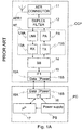
- FIG. 1A presents as a block diagram the connection of a prior art mobile station card CCP to an interface card slot in portable computer PC.
- Mobile station card CCP comprises antenna AER1, antenna connector 11, duplex filter 12, radio frequency part RF comprising on the reception side low noise amplifier LNA and receiver 13A and on the transmission side transmitter 13A and power amplifier PA.
- the mobile station card further comprises base band part 14 and first connecting part 15 comprising first data transfer interface 15A and first power transfer interface 15B for connecting the mobile station card to a computer.
- Mobile station card CCP receives a radio signal with its antenna from which the signal proceeds to over the antenna connector and the duplex filter to low noise amplifier LNA.
- the duplex filter separates the transmission and reception sides from each other and prevents transmitter 13B signal entering receiver 13A.
- LNA amplifies the antenna signal.
- Receiver 13A removes the carrier wave from the radio signal, i.e. demodulates the signal. The demodulated signal is decoded in base band part 14.
- Portable computer PC comprises microprocessor 17, power supply PS and second interface part 16 comprising second data transfer interface 16A and second power transfer interface 16B.
- the data decoded in base band part 14, e.g. data connected with data transfer, is transferred over first data transfer interface 15A and second data transfer interface 16A to microprocessor 17 of the computer.
- the data obtained from the computer to be transmitted is transferred over second data transfer interface 16A and first data transfer interface 15A to base band part 14 and radio frequency part 13 of the mobile station card in order to be coded and modulated, after which it is transmitted with transmitter 13B over duplex filter 12, antenna connector 11 and antenna AER1 to the free space.
- the mobile station card gets its operating voltage from power supply PS of the computer over second power supply interface 16B and first power transfer interface 15B.
- FIG 1B presents as a block diagram first power transfer interface 15B comprised in the first connecting part in Figure 1A.
- the first power transfer interface comprises first ground connector GCON1 and first plus-connector PCON1 in order to bring a supply voltage to the mobile station card.
- the mobile station card may comprise more than one voltage input, but for the invention it is sufficient that to the mobile station card it is brought over the power transfer interface for minus the ground to ground connector GCON1 and a positive voltage, e.g. +5 V, to first plus-connector PCON1.
- FIG. 1C presents as a block diagram second power transfer interface 16B comprised in the second connecting part in Figure 1A.
- the second power transfer interface comprises second ground connector GCON2 and second plus-connector PCON2 for bringing the supply voltage from the computer to first power transfer interface 15B of the mobile station card.
- FIG. 2a presents prior art mobile station card CCP connected to interface card slot SLOT in computer PC.
- the mobile station card comprises antenna AER1.
- the antenna in the immediate vicinity of the computer.
- the antenna forms together with the electrically conductive part of the cover of the computer, i.e. a Faraday's cage, a capacitive connection which is presented with imaginary capacitance C2, over which interference currents formed in the cover of the computer may cause electric interferencies in the antenna.
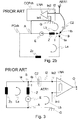
- Figure 2b presents as a simplified equivalent circuit the connection of the antenna interface of a mobile station card to an interference voltage.
- the circuit is a highly simplified one dimensional model of the 3-D reality, it helps to understand the interference mechanism and also the method of the invention for preventing interference from being passed to a sensitive radio receiver.
- the duplex filter and the antenna connector are omitted from the figure because they do not have any amplification of an antenna frequency signal and thus have no relevance for the explanation of the invention.
- the figure presents the electrically conductive cover PCch acting as Faradays cage of a portable computer and chassis CCPch of the mobile station card connected to ground.
- the high frequency interference currents formed in the cover of the computer are coupled to cover CCPch of the mobile station card by conduction or a capasitive or inductive coupling generated by the vicinity of conductive surfaces.
- a single-ended low noise amplifier LNA is used.
- LNA is single-ended, i.e. it has one asymmetric input and the ground of the mobile station card acts as a reference for this input.
- two inputs are shown, of which first input In1 is grounded over the mobile station card ground (G) to the cover of the computer and second input In2 is coupled over a duplex-filter to antenna AER1.
- the components contained by the computer induce in its cover PCch interference currents by the induction of electromagnetic radiation and also by conduction if the cover is connected also to the power supply of the computer, for example to its ground.
- the circuit shows two points, A and B, of cover PCch. Between these a voltage source E is placed representing the interference source and in series with it, the impedance Z which comprises also a frequency-dependent component.
- Point A is connected via cover PCch of the mobile station card further to the grounded first input In1 of LNA.
- Second input In2 of LNA is assumed to be coupled to the cover only with a capacitive coupling through point B over capacitance C2 shown in the x.
- Capacitance C2 is formed by the antenna of the mobile station card and the electrically conductive surfaces of the cover of the computer.
- the source of interference is represented by voltage source E, the internal impedance of which is Z.
- Current I caused by the source of interference is divided in point B into two branches.
- Current Ia first circulates in first loop La through second impedance Zc caused by cover PCch.
- Current Ib circulates in loop Lb first through capacitance C2 to second input In2 of LNA.
- First input In1 of LNA is in turn connected to point A, and accordingly current loop Lb is closed through the interference voltage (E, Z) back to point B.
- Figure 3 presents the prior art equivalent circuit in Figure 2b in such a way that antenna AER1 in Figure 2b is shown as AER1 on the side of capacitance C2 of LNA.
- the interference voltage is represented by voltage source E, the internal impedance of which is Z.
- the current caused by the interference source is divided in point B into two branches and it causes two current loops, as explained above in connection with Figure 2b.
- the interference voltages generated in the cover of the computer enter ground G of the mobile station and LNA combined to the antenna signal received by antenna AER1, in which case they also cause interference in output O of LNA.
- Figure 4A presents a connection according to the invention for reducing interference arriving at LNA.
- the interference voltage between points A and B formed in the electrically conductive cover of a computer is presented by voltage source E the internal impedance of which is Z.
- the antenna of a mobile station card it is used balanced antenna AER2 comprising two elements electrically isolated from each other, for example a dipole antenna, in which a capasitively coupled interference is assumed to arrive to the first element from point B and to the second element from point B'.
- the capacitive coupling of the first element of the dipole antenna is presented with capacitance C1 and the coupling over a capacitance of the second element to the cover of the computer is presented with capacitance C2. Between these there is a third impedance, Z'.
- the antenna has to be separated functionally from the cover of the computer and from the ground of the mobile station card in order to prevent interference occurring on the frequencies used by the mobile station card from being conducted to low noise amplifier LNA.
- the input of the single-ended low noise amplifier is arranged to be differential using suitable separating means, for example by using a symmetrification transformer i.e. balun Ba (Balanced - Unbalanced).
- the balun can be e.g. a component formed by two coils coiled on a circular core.
- the first i,e, primary coil BaP is connected between the elements of the two-part antenna and the second or secondary coil BaS is connected between second input In2 of the balun and ground or first input In1.
- the balun creates a floating coupling to the antenna connection in such a way that the increase of the potential of LNA, for example the increase of potential coming from the interference to input In1 connected to ground increases the potential of the signal coming to first input In1 by the same amount and the difference between them, or voltage, only depends on the voltage difference between the first and second element of the antenna generated by the radio waves received by the antenna. Interference voltages formed in the cover of the computer thus cause no interference in output O of the antenna interface.
- balun instead of a balun it is possible to use alternatively for example a transformer which at the same time adapts the impedance of the antenna interface suitable for circuit LNA receiving the antenna signal, or a balanced input SAW (Surface Acoustic Wave) - filter which at the same operates as a duplex-filter.
- a transformer which at the same time adapts the impedance of the antenna interface suitable for circuit LNA receiving the antenna signal, or a balanced input SAW (Surface Acoustic Wave) - filter which at the same operates as a duplex-filter.
- SAW Surface Acoustic Wave
- the antenna Entering of some interferencies to the antenna, on the reception frequency and in the frequency band near it, is prevented by the electrical isolating of the elements of an antenna. It is striven for to avoid electric couplings occurring on these frequencies formed between the antenna and the electrically conductive, interference reducing parts of the cover of the computer, or between the antenna and the ground of the mobile station card by isolation the antenna from said parts sufficiently well on the signal frequency.
- the signal frequency coupling between the elements of the antenna and said parts (cover, ground) is that weak, that in respect to the operation of a mobile station, no significant interference level can by captured by the antenna through that path and further through it to be amplified together with the useful signal.
- the elements of the antenna have preferably been isolated both galvanically and inductively and capacitively as well as possible, although capacitive and inductive coupling between the cover of the computer and the antenna may be formed as explained above.
- Said isolation means also prevent the operation of the case of a computer and the ground of a mobile station and the components connected to it as radiating elements. It is possible to adapt for example with a ring balun the impedance of an antenna connected to an antenna interface to be suitable for the interface, in which case the number of the secondary coil of the ring balun may comprise a number of turns different from that of the primary coil. An electric signal transferred from the primary side to the secondary side of a balun is not essentially changed except for a possible systematic change in its voltage due to said ratio between the turns.
- a balun and a single-ended antenna amplifier it is possible to use alternatively for example as an antenna interface a differential low noise amplifier as shown in Figure 4b.
- the components between the antenna and the low noise amplifier such as a duplex-filter or a Rx/Tx separation switch and antenna connectors, are not shown in the figure because they have no significant amplification nor attenuation. From the point of view of the invention they can be placed on either side of the balun.
- a balun can be situated for example in connection with the antenna interface of the radio receiver of a mobile station card between the leads coming from the antenna and the next component for example a duplex-filter or just before low noise amplifier LNA.
- it can be placed in connection with an external antenna, for example as an element of the antenna or antenna conductor. If the balun is placed for example in an external antenna between antenna elements and an antenna cable interference on the radio frequency of reception formed in the ground of LNA enter at least on the moment of reception through the conductor of the antenna cable from a first input to one end of the secondary side of the balun.
- a location in connection with the antenna or the antenna cable is a good place for a balun because in this way it is possible to use as the antenna of the mobile station card alternatively whichever, either a balanced two-pad antenna according to the invention which in this case itself prevents the interference occurring in the ground of the mobile station card from entering the voltage between the inputs of LNA, or a usual one-pad antenna, in which case the ground plane of which is the ground of the mobile station card.
- a balanced two-pad antenna according to the invention which in this case itself prevents the interference occurring in the ground of the mobile station card from entering the voltage between the inputs of LNA, or a usual one-pad antenna, in which case the ground plane of which is the ground of the mobile station card.
- the antenna side is chosen for the primary side of the balun and for the secondary side the side connecting the inputs of LNA.
- Figure 4b presents according to a second aspect of the invention as a simplified equivalent circuit a connection for reducing interference received by the radio receiver of a mobile station card.
- the antenna interface of the mobile station card comprises for supplying an antenna signal from the two antenna poles AP1 and AP2 to the two inputs In1, In2 isolated from ground G.
- ground G of the mobile station card is connected to neither input, nor is a balun required even for preventing the ground of mobile station card from acting as an antenna.
- Such an antenna interface can be for example be connected to a differential antenna amplifier.
- Figure 5b presents mobile station card CCP according to the invention comprising dipole antenna 2 and antenna conductors L1 and L2.
- the card is manufactured to be slightly longer than a PCMCIA interface card slot in order to leave dipole antenna 2 in its one end outside the interface card slot when the card is placed in the interface card slot.
- Dipole antenna 2 has preferably in one end been arranged to be folding vertically from the direction of the short edge supported by hinge pin A1, because the PCMCIA interface card slots normally are manufactured to horizontal in the normal operating position of a computer and the antenna operates best in vertical position at the reception of a in mobile communications networks normally used vertically polarised radio transmission.
- folding the antenna parallel to the card it requires less space and the card need not necessarily be removed for example when a portable computer is carried inside a briefcase.
- first contact surface P1 and P2 functioning as the antenna interface inputs (In1 and In2) of the mobile station card for two rods R1 and R2 of the dipole antenna.
- First rod R1 of the dipole antenna is connected using conductor L1 to first contact surface P1 and second rod R2 with conductor L2 to second contact surface P2.
- the conductors are connected to the next to each other ends of the rods, in the middle portion of the dipole antenna.
- the electric length of the dipole antenna is preferably 1 ⁇ 2 wavelength on the radio frequency used, but the physical length of the antenna can be shortened by using helix in one rod or in both.
- a dipole antenna in connection with a mobile station card by manufacturing the dipole antenna to be of equal length with shorter edge of the mobile station card.
- the length can be varied rather freely, but then it may be necessary to improve the adaptation of the antenna using a particular adapter circuit.
- a portion of rod R1 is coiled into helix H1 and a portion of rod R2 into helix H2.
- the dipole antenna shortened using the helixes can preferably be placed inside an electrically isolation cover, for example one made of plastic, in which case it is not damaged easily or get caught in objects, for example textiles.
- Conductors L1 and L2 can also preferably at least partly be substituted by connecting rods R1 and R2 of the dipole antenna into terminals P1 and P2 of the antenna interface of the mobile station card using conductors integrated in the cover protecting the rods of the dipole antenna.
- FIG. 6 presents balanced antenna AER1, according to the invention which also balances the antenna interface.
- the antenna comprises first rod R1 and second rod R2 connected to each other over the primary coil of balun Ba.
- the antenna also comprises first and second signal poles SP1 and SP2. Said first rod is functionally connected through the balun to the first signal pole and the second rod to the second signal pole.
- the antenna When the antenna is connected through its signal poles to a mobile station card it operates as the antenna of the mobile station card according to the connection in Figure 4a. In this way both of the rods of the antenna are electrically isolated on the radio reception frequency from the ground of the mobile station card and a mobile station card equipped with a single-ended antenna interface can avoid a major part of the interference entering the antenna signal through the ground.
- the antenna is suitable to used as the antenna of already existing mobile station cards equipped with a single-ended antenna interface provided that they are equipped with an interface for an external antenna. One of its signal poles is then connected to the terminal intended also for the signal arriving from the rod antenna of the antenna interface of the mobile station card. If the external antenna interface comprises also a second pole for connecting the ground plane of the antenna or one of the rods of a dipole antenna the first signal pole is connected to it, but if there is none the first signal pole can be connected alternatively to the ground of the mobile station card or to the ground of the computer if the computer and the mobile station card share the same ground, which often is the case.
- the connectors of the data transfer ports of a computer often comprise a grounded part.
- the antenna may also be provided with an adapter, on the opposite sides of which there are for example male and female connectors suitable for RS-232 serial port, and which adapter branches the grouded part of the port to the first signal pole of the antenna.
- a dipole antenna is one of the most popular two-pole antenna, because it has two distinct elements and thus it has the two poles.
- the electric length of the antenna is preferably a 1 ⁇ 4 - wavelength of the radio frequency used or a multiple of the 1 ⁇ 4 -wavelength. It can alternatively be 5/8 -wavelength.
- a dipole antenna can be made to be folding into two parts between rods R1 and R2, in which case the physical length of rods R1 and R2 can be increased with no need to sacrifice too much space for the transport and keeping of a mobile station card equipped with a dipole antenna.
- Figure 7 presents a method according to the invention for reducing the susceptibility for interference of a mobile station card when it is connected to an electronic device.
- the method begins in block 71 after which it is received in block radio waves as an electric signal between two antenna elements.
- the electric signal is transferred to a radio receiver keeping at the same the elements of the antenna isolated from the ground of the radio receiver in order to reduce the electric interference coming through the ground received by the radio receiver along with said electric signal.
- the received electric signal is transformed into such a from which can be utilised by said electronic device, for example into data to be transferred through a PCMCIA -interface card slot.
- said message is transferred to the electronic device using the mobile station card.
- a mobile station card according to the invention can be used also in electronic devices other than computers, which devices comprise a PCMCIA -interface.
- devices comprise a PCMCIA -interface.
- PCMCIA -interface e.g. drink or cigarette vending machines or machines remote controlled over a mobile telephone network or controlling functions built in so-called intelligent houses or offices, such as control of air conditioning or lighting.
- a mobile station card equipped with a PCMCIA -interface the manufacturer of such a device need take into account a mobile telephone network supported on the installation site, but he can equip all his devices with a PCMCIA -interface and a mobile station card suitable for each mobile telephone network provided by a separate manufacturer of mobile station cards.
- a mobile station card according to the invention can naturally be realised according to other generally used types of interface cards without deviating from the scope of the invention.
- the advantage of the invention is that a mobile station card connectable to a computer can avoid for a major part the electronic interference caused by the computer which interference would otherwise cause interference and errors in the data received by the mobile station card. Further, by using the connection according to the invention it is possible to reduce the interference caused in the computer by a radio transmission which is particularly preferable for the disturbance-free operation of audio-video devices connected to the computer.
- the active interference reduction according to the invention is particularly well suited for use in connection with other interference suppression, for example to be used together with an external, two-part antenna to be placed at a distance of 0,5 m from the computer. In such a case the field strength of the interference emission received by the antenna is lower also because of the distance and in addition to it the coupling of the interference to the elements of the antenna is more symmetric than if an antenna placed closer to the computer were used.
- a vertical antenna is used as a part of the interference reduction equipment according to the invention.
- a vertical antenna operates best at receiving vertically polarised radio transmission.
- the invention can naturally equally well be used for receiving other than vertically polarised radio transmissions.
- the antenna is preferably arranged according to the polarisation plane of the radio transmission to be received.
Abstract
Description
- The present invention relates to reducing the interference received from a computer by a radio communication device detachably connectable inside the computer.
- Various accessories can be connected in a computer using the interface standardised for portable computers. The Nokia Cellular Card Phone- (CCP) mobile telephone card, introduced in the CeBit -97 exhibition and now in the market, is an example of such a PC - card (prior known as PCMCIA). A computer can be connected to the public telephone network using the mobile station card. Thus it is possible, e.g. to receive and send E-mail using it.
- An internal PC-card slot inside a portable computer is a problematic place for a radio receiver due to the electromagnetic interference created by the computer. A mobile telephone card according to the GSM -standard ETSI TS 101 157 V6.0.0 (1998-01) must be capable of receiving with its antenna even a very weak radio signal of the level of -102 dBm, while some portable computers have been measured to engender, to the same antenna, radio interference even on the level of -80 dBm, i.e. with over hundred fold the output. This radio interference disturbs the reception of radio signals. Because of this, the CCP mobile telephone card is provided with also a connector for an external antenna to which connector a separate external antenna can be connected with cable at the distance of ca. 0,5 m from the computer. The use of a separate external antenna is however more laborious than using the own antenna and all interference not even using an external antenna is possible to avoid which will cause errors in the received data stream. Errors slow down the data transfer because normally data has to be delivered error-free and meaning that corrupted data packets have be retransmitted. On speech transfer, errors cause deteriorated voice quality and at worst, on reception, even a complete muting when the amount of errors further increases.
- In order to meet the requirements concerning electromagnetic compatibility portable computers usually have a conductive shielding surrounding their high-speed digital circuits. This is typically realised in a computer with a plastic chassis by applying on the inside of the case of the computer a metal foil or coating or -plates that are electrically connected to each other, and the foil, coating or plates may be grounded.. A conductive enclosure, that prevents any leakage of electromagnatic radiation, known as Faraday's cage is formed in order to reduce interference . The case does not always form an ideal Faraday's cage but all holes and especially long gaps or poorly sealed contact surfaces reduce its capability of keeping electromagnetic emission inside it. The internal parts of a computer emitting high frequency radio interference inside a computer induce interference currents on the surface of the the case. Further, if the case is grounded, interference caused by computer parts is conducted to the case.
- Present mobile stations use normally radio frequencies of approximately 800 - 1900 MHz. Their wavelengths are respectively approximately 0,38 m - 0,16 m. The outer dimensions of a portable computer and accordingly those of the Faraday's cage thus formed are typically of the same magnitude as said wavelengths. The case of a computer also emits outward interference on the same frequency received by the mobile station card intensified by resonance formed. The antenna of a normal mobile station is connected to an antenna connector which in turn is connected to a separator, e.g. a duplex filter, a circulator or a TX/RX -switch separating the transmitter and receiver from each other. This separator in turn is connected to low noise amplifier LNA which raises the signal power received by the antenna to a safe level above the disturbance power. The LNA is the first component of the mobile station card which amplifies the radio frequency signal received by the antenna. Normally, the LNA is single-ended, i.e. its first input is grounded to the cover of the system formed by the mobile station card and the computer. The interference conducted to the cover is amplified together with the actual antenna signal arriving from the antenna to a second input of the connection. In addition to it the radio interference emitted outward by the cover of the computer induces in the antenna error currents that are also conducted to the antenna connection. A current loop is formed to the interference current leaving the source of interference in the computer closed through the antenna and LNA.
- Normally in radio receivers radio interference is accounted for in the design of a device in such a way that the components causing most interference are striven to be placed far from the antenna and the antenna connector and in them it is possible to dimension the components in a way ideal from the point of view of reception. A mobile station card on the other hand can be connected to a computer from any manufacturer. The regulations concerning the electromagnetic compatibility of those are, however, very loose thinking the use of the mobile station card, in which case the above mentioned over hundred fold interference power compared with the received signal can quite well be realised without deviating from these regulations. A mobile station card manufactured to a PC -card and a computer are not designed together at all. A manufacturer of mobile station cards has to design the mobile station cards produced by him to tolerate radio interference caused by very different computers.
- Now a method and a device are invented, by which it is possible to increase the immunity of a mobile station card connected to a computer to electromagnetic interference generated by the computer. According to the invention a differential antenna interface isolated from the cover of said system is arranged for the antenna of the mobile station card. Some of interference conducted through the ground of a computer is reduced by connecting the antenna either to a single-ended antenna interface using a symmetrification transformer i.e. balun or by alternatively by using a differential connection galvanically isolated from the cover of the system. The invention prevents or at least reduces the access conducted interference to the antenna interface to interfere the radio signal received by the mobile station card.
- A mobile station card for receiving radio transmissions comprising
- an interface for connecting said mobile station card to a card slot of an electronic device,
- a radio receiver,
- an antenna, and
- a ground is characterised in that
- said radio receiver has a differential input with a first input node and a second input node,
- said antenna comprises a first antenna pole and a second antenna pole for receiving a radio signal as an electric signal between the first and second antenna poles,
- said first antenna pole is arranged to be functionally connected to said first input node and said second antenna pole is arranged to be functionally connected to said second input node.
-
- An antenna for a mobile station card, comprising a first antenna element, a second antenna element, and an interface comprising a first signal node and a second signal node is characterised in that
- the antenna is arranged to be connected to a mobile station card as the antenna of said mobile station card, which card is connectable to an electronic device,
- the antenna comprises separating means having a first side and a second side,
- said first side is functionally connected between said first and second antenna elements, and
- said second side is functionally connected between said first and second signal nodes in order to arrange a differential input in said connection.
-
- A method for reducing interference at radio reception when the radio receiver is connected to an electronic device is characterised in
- transforming received radio waves into an electric signal between two antenna elements,
- transferring said electric signal to the radio receiver keeping the antenna elements electrically separated from the ground of the radio receiver in order to transfer the signal to the radio receiver and to reduce the electric interference arriving through the ground and mixing into said electric signal,
- transforming said electric signal in the radio receiver to such a form which can be utilised by said electronic device, and
- transferring the message to said electronic device.
-
- The invention is explained in the following in detail using examples and with reference to enclosed figures of which
- Figure 1A
- presents as a block diagram the connection of a prior art mobile station card to a computer;
- Figure 1B
- presents as a block diagram the power transmission connection belonging to a first connecting part in Figure 1A;
- Figure 1C
- presents as a block diagram the power transmission connection belonging to a second connecting part in Figure 1A;
- Figure 2a
- presents a prior art mobile station card connected to a computer;
- Figure 2b
- presents as a simplified circuit the connection of the antenna interface of a prior art mobile station card connected to a computer to an interference voltage;
- Figure 3
- presents the prior art equivalent circuit in Figure 2b in the form of a circuit comprising two parallel loops;
- Figure 4a
- presents as a simplified equivalent circuit the connection according to a first aspect of the invention for reducing interference received by the radio receiver of a mobile station card;
- Figure 4b
- presents as a simplified equivalent circuit the connection according to a second aspect of the invention for reducing interference received by the radio receiver of a mobile station card;
- Figure 5
- presents a mobile station card according to the invention;
- Figure 6
- presents an antenna according to the invention; and
- Figure 7
- presents a method according to the invention for increasing the immunity to interference of a mobile station card connected to an electronic device.
- Figure 1A presents as a block diagram the connection of a prior art mobile station card CCP to an interface card slot in portable computer PC. Mobile station card CCP comprises antenna AER1,
antenna connector 11,duplex filter 12, radio frequency part RF comprising on the reception side low noise amplifier LNA andreceiver 13A and on thetransmission side transmitter 13A and power amplifier PA. The mobile station card further comprisesbase band part 14 and first connectingpart 15 comprising firstdata transfer interface 15A and firstpower transfer interface 15B for connecting the mobile station card to a computer. Mobile station card CCP receives a radio signal with its antenna from which the signal proceeds to over the antenna connector and the duplex filter to low noise amplifier LNA. The duplex filter separates the transmission and reception sides from each other and preventstransmitter 13Bsignal entering receiver 13A. LNA amplifies the antenna signal.Receiver 13A removes the carrier wave from the radio signal, i.e. demodulates the signal. The demodulated signal is decoded inbase band part 14. - Portable computer PC comprises
microprocessor 17, power supply PS andsecond interface part 16 comprising seconddata transfer interface 16A and secondpower transfer interface 16B. The data decoded inbase band part 14, e.g. data connected with data transfer, is transferred over firstdata transfer interface 15A and seconddata transfer interface 16A tomicroprocessor 17 of the computer. Correspondingly, the data obtained from the computer to be transmitted is transferred over seconddata transfer interface 16A and firstdata transfer interface 15A tobase band part 14 and radio frequency part 13 of the mobile station card in order to be coded and modulated, after which it is transmitted withtransmitter 13B overduplex filter 12,antenna connector 11 and antenna AER1 to the free space. The mobile station card gets its operating voltage from power supply PS of the computer over secondpower supply interface 16B and firstpower transfer interface 15B. - Figure 1B presents as a block diagram first
power transfer interface 15B comprised in the first connecting part in Figure 1A. The first power transfer interface comprises first ground connector GCON1 and first plus-connector PCON1 in order to bring a supply voltage to the mobile station card. Naturally the mobile station card may comprise more than one voltage input, but for the invention it is sufficient that to the mobile station card it is brought over the power transfer interface for minus the ground to ground connector GCON1 and a positive voltage, e.g. +5 V, to first plus-connector PCON1. - Figure 1C presents as a block diagram second
power transfer interface 16B comprised in the second connecting part in Figure 1A. The second power transfer interface comprises second ground connector GCON2 and second plus-connector PCON2 for bringing the supply voltage from the computer to firstpower transfer interface 15B of the mobile station card. - Figure 2a presents prior art mobile station card CCP connected to interface card slot SLOT in computer PC. The mobile station card comprises antenna AER1. The antenna in the immediate vicinity of the computer. In this way the antenna forms together with the electrically conductive part of the cover of the computer, i.e. a Faraday's cage, a capacitive connection which is presented with imaginary capacitance C2, over which interference currents formed in the cover of the computer may cause electric interferencies in the antenna.
- Figure 2b presents as a simplified equivalent circuit the connection of the antenna interface of a mobile station card to an interference voltage. Although the circuit is a highly simplified one dimensional model of the 3-D reality, it helps to understand the interference mechanism and also the method of the invention for preventing interference from being passed to a sensitive radio receiver. The duplex filter and the antenna connector are omitted from the figure because they do not have any amplification of an antenna frequency signal and thus have no relevance for the explanation of the invention. The figure presents the electrically conductive cover PCch acting as Faradays cage of a portable computer and chassis CCPch of the mobile station card connected to ground. The high frequency interference currents formed in the cover of the computer are coupled to cover CCPch of the mobile station card by conduction or a capasitive or inductive coupling generated by the vicinity of conductive surfaces. Here in order to present the inputs of the radio receiver of the mobile station card, a single-ended low noise amplifier LNA is used. LNA is single-ended, i.e. it has one asymmetric input and the ground of the mobile station card acts as a reference for this input. However, in this case two inputs are shown, of which first input In1 is grounded over the mobile station card ground (G) to the cover of the computer and second input In2 is coupled over a duplex-filter to antenna AER1. The components contained by the computer induce in its cover PCch interference currents by the induction of electromagnetic radiation and also by conduction if the cover is connected also to the power supply of the computer, for example to its ground. The circuit shows two points, A and B, of cover PCch. Between these a voltage source E is placed representing the interference source and in series with it, the impedance Z which comprises also a frequency-dependent component. Point A is connected via cover PCch of the mobile station card further to the grounded first input In1 of LNA. Second input In2 of LNA is assumed to be coupled to the cover only with a capacitive coupling through point B over capacitance C2 shown in the x. Capacitance C2 is formed by the antenna of the mobile station card and the electrically conductive surfaces of the cover of the computer.
- The source of interference is represented by voltage source E, the internal impedance of which is Z. Current I caused by the source of interference is divided in point B into two branches. Current Ia first circulates in first loop La through second impedance Zc caused by cover PCch. Current Ib circulates in loop Lb first through capacitance C2 to second input In2 of LNA. First input In1 of LNA is in turn connected to point A, and accordingly current loop Lb is closed through the interference voltage (E, Z) back to point B.
- Figure 3 presents the prior art equivalent circuit in Figure 2b in such a way that antenna AER1 in Figure 2b is shown as AER1 on the side of capacitance C2 of LNA. The interference voltage is represented by voltage source E, the internal impedance of which is Z. The current caused by the interference source is divided in point B into two branches and it causes two current loops, as explained above in connection with Figure 2b. The interference voltages generated in the cover of the computer enter ground G of the mobile station and LNA combined to the antenna signal received by antenna AER1, in which case they also cause interference in output O of LNA.
- Figure 4A presents a connection according to the invention for reducing interference arriving at LNA. Here too, the interference voltage between points A and B formed in the electrically conductive cover of a computer is presented by voltage source E the internal impedance of which is Z. As the antenna of a mobile station card it is used balanced antenna AER2 comprising two elements electrically isolated from each other, for example a dipole antenna, in which a capasitively coupled interference is assumed to arrive to the first element from point B and to the second element from point B'. The capacitive coupling of the first element of the dipole antenna is presented with capacitance C1 and the coupling over a capacitance of the second element to the cover of the computer is presented with capacitance C2. Between these there is a third impedance, Z'. Voltage source E generates a current passing through impedances Z and Z' connected in series, a part of which current passes from point B to point A through third impedance Zc formed by the cover. If it is assumed that the interference coming to both elements of the dipole antenna over a capacitive coupling is coming from the same point, i.e.
- Entering of some interferencies to the antenna, on the reception frequency and in the frequency band near it, is prevented by the electrical isolating of the elements of an antenna. It is striven for to avoid electric couplings occurring on these frequencies formed between the antenna and the electrically conductive, interference reducing parts of the cover of the computer, or between the antenna and the ground of the mobile station card by isolation the antenna from said parts sufficiently well on the signal frequency. In order to realise the electric isolation, the signal frequency coupling between the elements of the antenna and said parts (cover, ground) is that weak, that in respect to the operation of a mobile station, no significant interference level can by captured by the antenna through that path and further through it to be amplified together with the useful signal. The elements of the antenna have preferably been isolated both galvanically and inductively and capacitively as well as possible, although capacitive and inductive coupling between the cover of the computer and the antenna may be formed as explained above.
- Said isolation means (balun, transformer, SAW -element) also prevent the operation of the case of a computer and the ground of a mobile station and the components connected to it as radiating elements. It is possible to adapt for example with a ring balun the impedance of an antenna connected to an antenna interface to be suitable for the interface, in which case the number of the secondary coil of the ring balun may comprise a number of turns different from that of the primary coil. An electric signal transferred from the primary side to the secondary side of a balun is not essentially changed except for a possible systematic change in its voltage due to said ratio between the turns. Instead of a balun and a single-ended antenna amplifier it is possible to use alternatively for example as an antenna interface a differential low noise amplifier as shown in Figure 4b. The components between the antenna and the low noise amplifier, such as a duplex-filter or a Rx/Tx separation switch and antenna connectors, are not shown in the figure because they have no significant amplification nor attenuation. From the point of view of the invention they can be placed on either side of the balun.
- A balun can be situated for example in connection with the antenna interface of the radio receiver of a mobile station card between the leads coming from the antenna and the next component for example a duplex-filter or just before low noise amplifier LNA. Alternatively, it can be placed in connection with an external antenna, for example as an element of the antenna or antenna conductor. If the balun is placed for example in an external antenna between antenna elements and an antenna cable interference on the radio frequency of reception formed in the ground of LNA enter at least on the moment of reception through the conductor of the antenna cable from a first input to one end of the secondary side of the balun. A location in connection with the antenna or the antenna cable is a good place for a balun because in this way it is possible to use as the antenna of the mobile station card alternatively whichever, either a balanced two-pad antenna according to the invention which in this case itself prevents the interference occurring in the ground of the mobile station card from entering the voltage between the inputs of LNA, or a usual one-pad antenna, in which case the ground plane of which is the ground of the mobile station card. Such a solution is presented later in Figure 6.
- In this case the antenna side is chosen for the primary side of the balun and for the secondary side the side connecting the inputs of LNA.
- Figure 4b presents according to a second aspect of the invention as a simplified equivalent circuit a connection for reducing interference received by the radio receiver of a mobile station card. The antenna interface of the mobile station card comprises for supplying an antenna signal from the two antenna poles AP1 and AP2 to the two inputs In1, In2 isolated from ground G. In this case ground G of the mobile station card is connected to neither input, nor is a balun required even for preventing the ground of mobile station card from acting as an antenna. Such an antenna interface can be for example be connected to a differential antenna amplifier.
- Figure 5b presents mobile station card CCP according to the invention comprising dipole antenna 2 and antenna conductors L1 and L2. The card is manufactured to be slightly longer than a PCMCIA interface card slot in order to leave dipole antenna 2 in its one end outside the interface card slot when the card is placed in the interface card slot. Dipole antenna 2 has preferably in one end been arranged to be folding vertically from the direction of the short edge supported by hinge pin A1, because the PCMCIA interface card slots normally are manufactured to horizontal in the normal operating position of a computer and the antenna operates best in vertical position at the reception of a in mobile communications networks normally used vertically polarised radio transmission. By folding the antenna parallel to the card it requires less space and the card need not necessarily be removed for example when a portable computer is carried inside a briefcase. On the top surface of the mobile station card there are two contact surfaces P1 and P2 functioning as the antenna interface inputs (In1 and In2) of the mobile station card for two rods R1 and R2 of the dipole antenna. First rod R1 of the dipole antenna is connected using conductor L1 to first contact surface P1 and second rod R2 with conductor L2 to second contact surface P2. The conductors are connected to the next to each other ends of the rods, in the middle portion of the dipole antenna. The electric length of the dipole antenna is preferably ½ wavelength on the radio frequency used, but the physical length of the antenna can be shortened by using helix in one rod or in both. In this way it is possible to solve the technical problem of placing a dipole antenna in connection with a mobile station card by manufacturing the dipole antenna to be of equal length with shorter edge of the mobile station card. The length can be varied rather freely, but then it may be necessary to improve the adaptation of the antenna using a particular adapter circuit. In the figure a portion of rod R1 is coiled into helix H1 and a portion of rod R2 into helix H2. The dipole antenna shortened using the helixes can preferably be placed inside an electrically isolation cover, for example one made of plastic, in which case it is not damaged easily or get caught in objects, for example textiles. Conductors L1 and L2 can also preferably at least partly be substituted by connecting rods R1 and R2 of the dipole antenna into terminals P1 and P2 of the antenna interface of the mobile station card using conductors integrated in the cover protecting the rods of the dipole antenna.
- Figure 6 presents balanced antenna AER1, according to the invention which also balances the antenna interface. The antenna comprises first rod R1 and second rod R2 connected to each other over the primary coil of balun Ba. The antenna also comprises first and second signal poles SP1 and SP2. Said first rod is functionally connected through the balun to the first signal pole and the second rod to the second signal pole. When the antenna is connected through its signal poles to a mobile station card it operates as the antenna of the mobile station card according to the connection in Figure 4a. In this way both of the rods of the antenna are electrically isolated on the radio reception frequency from the ground of the mobile station card and a mobile station card equipped with a single-ended antenna interface can avoid a major part of the interference entering the antenna signal through the ground. The antenna is suitable to used as the antenna of already existing mobile station cards equipped with a single-ended antenna interface provided that they are equipped with an interface for an external antenna. One of its signal poles is then connected to the terminal intended also for the signal arriving from the rod antenna of the antenna interface of the mobile station card. If the external antenna interface comprises also a second pole for connecting the ground plane of the antenna or one of the rods of a dipole antenna the first signal pole is connected to it, but if there is none the first signal pole can be connected alternatively to the ground of the mobile station card or to the ground of the computer if the computer and the mobile station card share the same ground, which often is the case. For example the connectors of the data transfer ports of a computer often comprise a grounded part. The antenna may also be provided with an adapter, on the opposite sides of which there are for example male and female connectors suitable for RS-232 serial port, and which adapter branches the grouded part of the port to the first signal pole of the antenna.
- In this text two-part antenna having radiating antenna elements is used as an example to aid understanding of the present invention. One should appreciate that any antenna having two poles may be used. A dipole antenna is one of the most popular two-pole antenna, because it has two distinct elements and thus it has the two poles. There is also a number of other two-pole antennae suitable for the invention including meander- and loop antennae, an asymmetric antenna and an antenna the antenna element of which is formed of more than one element. The electric length of the antenna is preferably a ¼ - wavelength of the radio frequency used or a multiple of the ¼ -wavelength. It can alternatively be 5/8 -wavelength.
- A dipole antenna can be made to be folding into two parts between rods R1 and R2, in which case the physical length of rods R1 and R2 can be increased with no need to sacrifice too much space for the transport and keeping of a mobile station card equipped with a dipole antenna.
- Figure 7 presents a method according to the invention for reducing the susceptibility for interference of a mobile station card when it is connected to an electronic device. The method begins in
block 71 after which it is received in block radio waves as an electric signal between two antenna elements. Inblock 73 the electric signal is transferred to a radio receiver keeping at the same the elements of the antenna isolated from the ground of the radio receiver in order to reduce the electric interference coming through the ground received by the radio receiver along with said electric signal. Inblock 74 the received electric signal is transformed into such a from which can be utilised by said electronic device, for example into data to be transferred through a PCMCIA -interface card slot. Inblock 75 said message is transferred to the electronic device using the mobile station card. - A mobile station card according to the invention can be used also in electronic devices other than computers, which devices comprise a PCMCIA -interface. As examples of such it can be mentioned e.g. drink or cigarette vending machines or machines remote controlled over a mobile telephone network or controlling functions built in so-called intelligent houses or offices, such as control of air conditioning or lighting. By using a mobile station card equipped with a PCMCIA -interface the manufacturer of such a device need take into account a mobile telephone network supported on the installation site, but he can equip all his devices with a PCMCIA -interface and a mobile station card suitable for each mobile telephone network provided by a separate manufacturer of mobile station cards.
- A mobile station card according to the invention can naturally be realised according to other generally used types of interface cards without deviating from the scope of the invention.
- The advantage of the invention is that a mobile station card connectable to a computer can avoid for a major part the electronic interference caused by the computer which interference would otherwise cause interference and errors in the data received by the mobile station card. Further, by using the connection according to the invention it is possible to reduce the interference caused in the computer by a radio transmission which is particularly preferable for the disturbance-free operation of audio-video devices connected to the computer. The active interference reduction according to the invention is particularly well suited for use in connection with other interference suppression, for example to be used together with an external, two-part antenna to be placed at a distance of 0,5 m from the computer. In such a case the field strength of the interference emission received by the antenna is lower also because of the distance and in addition to it the coupling of the interference to the elements of the antenna is more symmetric than if an antenna placed closer to the computer were used.
- In the above examples a vertical antenna is used as a part of the interference reduction equipment according to the invention. A vertical antenna operates best at receiving vertically polarised radio transmission. The invention can naturally equally well be used for receiving other than vertically polarised radio transmissions. In such a case the antenna is preferably arranged according to the polarisation plane of the radio transmission to be received.
- The above is a description of the realisation of the invention and its embodiments utilising examples. It is self evident to persons skilled in the art that the invention is not limited to the details of the above presented examples and that the invention can be realised also in other embodiments without deviating from the characteristics of the invention. The presented embodiments should be regarded as illustrating but not limiting. Thus the possibilities to realise and use the invention are limited only by the enclosed claims. Thus different embodiments of the invention specified by the claims, also equivalent embodiments, are included in the scope of the invention.
Claims (10)
- A mobile station card (CCP) for receiving radio transmissions comprisingan interface (15) for connecting said mobile station card to a card slot (PCMCIA) of an electronic device (PC),a radio receiver (13A),an antenna (AER2), anda ground (G), characterised in that said radio receiver has a differential input (LNA&Ba, LNA2) with a first input node (In1) and a second input node (In2),said antenna (AER2) comprises a first antenna pole (AP1) and a second antenna pole (AP2) for receiving a radio signal as an electric signal between the first and second antenna poles,said first antenna pole (AP1) is arranged to be functionally connected to said first input node (In1) and said second antenna pole (AP2) is arranged to be functionally connected to said second input node (In2).
- A mobile station card according to Claim 1, characterised in thatboth antenna poles (R1, R2) are electrically isolated from the ground (G) of the mobile station card in order to reduce radio interference of said ground disturbing the reception of radio signals caused by the electronic device (PC) using the mobile station card.
- A mobile station card according to Claim 1, characterised in thatthe first input (In1) is functionally connected to ground (G), andthe mobile station card comprises separating means (Ba) having a first side (BaP) and a second side (BaS), andsaid first side (BaP) is functionally connected between said first and second antenna poles, andsaid second side (BaS) is functionally connected between the second input and ground (G) in order to arrange said differential input.
- A mobile station card according to Claim 1, characterised in thatboth inputs (In1, In2) of the radio receiver are electrically separated from the ground (G) of the mobile station card, andsaid first antenna pole is connected using first coupling means (1, 11, 12) to the first input (In1) and the second antenna pole using second coupling means (

- A mobile station card according to Claim 1, characterised in thatsaid antenna comprises a first antenna element (R1) and a second antenna element (R2), andsaid second antenna element (R2) is arranged as the ground plane of said first antenna element (R1).
- A mobile station card according to Claim 1, characterised in thatsaid antenna has one of the following constructions: loop antenna, fragment antenna, helix-antenna, asymmetric antenna and dipole antenna.
- A mobile station card according to Claim 1, characterised in thatsaid antenna comprises a first antenna element (R1) and a second antenna element (R2), andat least another of said antenna elements (R1, R2) comprises a helix.
- A mobile station card according to Claim 1, characterised in thatit is arranged to be a PCMCIA-interface card.
- An antenna (AER2) for a mobile station card (CCP), comprising a first antenna element (R1), a second antenna element (R2), and an interface comprising a first signal node (SP1) and a second signal node (SP2), characterised in thatthe antenna is arranged to be connected to a mobile station card (CCP) as the antenna (AER2) of said mobile station card, which card is connectable to an electronic device (PC),the antenna comprises separating means (Ba) having a first side (BaP) and a second side (BaS),said first side (BaP) is functionally connected between said first and second antenna elements (R1, R2), andsaid second side (BaS) is functionally connected between said first and second signal nodes (SP1, SP2) in order to arrange a differential input in said connection.
- A method for reducing interference (Ib) at radio reception when the radio receiver (CCP) is connected to an electronic device (PC), characterised intransforming (72) received radio waves into an electric signal between two antenna elements,transferring (73) said electric signal to the radio receiver keeping the antenna elements electrically separated from the ground of the radio receiver in order to transfer the signal to the radio receiver and to reduce the electric interference arriving through the ground and mixing into said electric signal,transforming (74) said electric signal in the radio receiver to such a form which can be utilised by said electronic device, andtransferring (75) the message to said electronic device.
Applications Claiming Priority (2)
| Application Number | Priority Date | Filing Date | Title |
|---|---|---|---|
| FI981604A FI105298B (en) | 1998-07-14 | 1998-07-14 | Method and equipment to reduce interference |
| FI981604 | 1998-07-14 |
Publications (2)
| Publication Number | Publication Date |
|---|---|
| EP0973280A2 true EP0973280A2 (en) | 2000-01-19 |
| EP0973280A3 EP0973280A3 (en) | 2003-12-03 |
Family
ID=8552190
Family Applications (1)
| Application Number | Title | Priority Date | Filing Date |
|---|---|---|---|
| EP99112461A Withdrawn EP0973280A3 (en) | 1998-07-14 | 1999-06-30 | A method and a device for reducing interference |
Country Status (2)
| Country | Link |
|---|---|
| EP (1) | EP0973280A3 (en) |
| FI (1) | FI105298B (en) |
Cited By (4)
| Publication number | Priority date | Publication date | Assignee | Title |
|---|---|---|---|---|
| DE10159911A1 (en) * | 2001-12-06 | 2003-06-26 | Rohde & Schwarz | Controlled data section acceptance involves starting acceptance of next data section according to difference between current time marker, predicted time marker for next data section |
| GB2430077A (en) * | 2005-09-08 | 2007-03-14 | Motorola Inc | Balun coupling arrangement between an antenna and a wireless modem card |
| CN1332511C (en) * | 2003-04-14 | 2007-08-15 | 夏普株式会社 | Wireless transmission module |
| WO2007123454A1 (en) * | 2006-04-25 | 2007-11-01 | Laird Technologies Ab | Antenna device and portable radio communication device comprising such antenna device |
Citations (4)
| Publication number | Priority date | Publication date | Assignee | Title |
|---|---|---|---|---|
| WO1994021058A1 (en) * | 1993-03-04 | 1994-09-15 | Telefonaktiebolaget Lm Ericsson | Modular radio communications system |
| US5550554A (en) * | 1993-05-06 | 1996-08-27 | At&T Global Information Solutions Company | Antenna apparatus |
| US5583521A (en) * | 1995-08-11 | 1996-12-10 | Gec Plessey Semiconductors, Inc. | Compact antenna for portable microwave radio |
| US5680144A (en) * | 1996-03-13 | 1997-10-21 | Nokia Mobile Phones Limited | Wideband, stacked double C-patch antenna having gap-coupled parasitic elements |
-
1998
- 1998-07-14 FI FI981604A patent/FI105298B/en active
-
1999
- 1999-06-30 EP EP99112461A patent/EP0973280A3/en not_active Withdrawn
Patent Citations (4)
| Publication number | Priority date | Publication date | Assignee | Title |
|---|---|---|---|---|
| WO1994021058A1 (en) * | 1993-03-04 | 1994-09-15 | Telefonaktiebolaget Lm Ericsson | Modular radio communications system |
| US5550554A (en) * | 1993-05-06 | 1996-08-27 | At&T Global Information Solutions Company | Antenna apparatus |
| US5583521A (en) * | 1995-08-11 | 1996-12-10 | Gec Plessey Semiconductors, Inc. | Compact antenna for portable microwave radio |
| US5680144A (en) * | 1996-03-13 | 1997-10-21 | Nokia Mobile Phones Limited | Wideband, stacked double C-patch antenna having gap-coupled parasitic elements |
Cited By (6)
| Publication number | Priority date | Publication date | Assignee | Title |
|---|---|---|---|---|
| DE10159911A1 (en) * | 2001-12-06 | 2003-06-26 | Rohde & Schwarz | Controlled data section acceptance involves starting acceptance of next data section according to difference between current time marker, predicted time marker for next data section |
| DE10159911B4 (en) * | 2001-12-06 | 2005-12-22 | Rohde & Schwarz Gmbh & Co. Kg | Method for the targeted acceptance of data sections |
| CN1332511C (en) * | 2003-04-14 | 2007-08-15 | 夏普株式会社 | Wireless transmission module |
| GB2430077A (en) * | 2005-09-08 | 2007-03-14 | Motorola Inc | Balun coupling arrangement between an antenna and a wireless modem card |
| GB2430077B (en) * | 2005-09-08 | 2008-02-13 | Motorola Inc | Antenna arrangement having a coupling for use with a wireless modem card and a combination of the arrangement and card |
| WO2007123454A1 (en) * | 2006-04-25 | 2007-11-01 | Laird Technologies Ab | Antenna device and portable radio communication device comprising such antenna device |
Also Published As
| Publication number | Publication date |
|---|---|
| EP0973280A3 (en) | 2003-12-03 |
| FI105298B (en) | 2000-07-14 |
| FI981604A0 (en) | 1998-07-14 |
| FI981604A (en) | 2000-01-15 |
Similar Documents
| Publication | Publication Date | Title |
|---|---|---|
| US7889022B2 (en) | Electromagnetically coupled interconnect system architecture | |
| US7046124B2 (en) | Power line coupling device and method of using the same | |
| CN102868419B (en) | Transceiver and integrated circuit | |
| JP5634577B2 (en) | Communication device and coupler for communication device | |
| KR100757506B1 (en) | Antenna device and radio communication device | |
| EP0323614B1 (en) | Rotable contactless antenna coupler and antenna | |
| EP2360779B1 (en) | Radio transmission system and electronic device | |
| RU2143160C1 (en) | Balancer, radio communication device, and antenna assembly designing process | |
| EA006284B1 (en) | High frequency network multiplexed communications over various lines using multiple modulated carrier frequencies | |
| CN107925430B (en) | In-band full duplex complementary antenna | |
| US8558634B2 (en) | High-frequency coupler and communication device | |
| CN104604144A (en) | Transceiver front-end | |
| US8130158B2 (en) | Antenna apparatus and communication system including the same | |
| KR20190064571A (en) | Coaxial Data Communication with Reduced EMI | |
| CN102857248A (en) | Transceiver and method thereof | |
| EP0973280A2 (en) | A method and a device for reducing interference | |
| US7242361B2 (en) | Antenna structure with filter effect | |
| GB2442032A (en) | Earphone cable antenna arrangements and circuitry | |
| US9048547B2 (en) | Air loop antenna for shared AM/FM | |
| KR19990023474A (en) | Wireless terminal suitable for inductive coupling with radio | |
| US6757386B1 (en) | Apparatus, system, and method for efficient reduction of electromagnetic interference in telecommunications equipment | |
| ES2622073T3 (en) | Coupler for wireless communications | |
| CN212011275U (en) | Antenna apparatus for wireless power charging and near field communication | |
| WO2000046873A1 (en) | Wireless phone design for improving radiation performance | |
| CN215773083U (en) | Communication isolation circuit and communication isolator |
Legal Events
| Date | Code | Title | Description |
|---|---|---|---|
| PUAI | Public reference made under article 153(3) epc to a published international application that has entered the european phase |
Free format text: ORIGINAL CODE: 0009012 |
|
| AK | Designated contracting states |
Kind code of ref document: A2 Designated state(s): AT BE CH CY DE DK ES FI FR GB GR IE IT LI LU MC NL PT SE |
|
| AX | Request for extension of the european patent |
Free format text: AL;LT;LV;MK;RO;SI |
|
| RAP1 | Party data changed (applicant data changed or rights of an application transferred) |
Owner name: NOKIA CORPORATION |
|
| PUAL | Search report despatched |
Free format text: ORIGINAL CODE: 0009013 |
|
| AK | Designated contracting states |
Kind code of ref document: A3 Designated state(s): AT BE CH CY DE DK ES FI FR GB GR IE IT LI LU MC NL PT SE |
|
| AX | Request for extension of the european patent |
Extension state: AL LT LV MK RO SI |
|
| RIC1 | Information provided on ipc code assigned before grant |
Ipc: 7H 04B 1/38 B Ipc: 7H 04B 1/12 B Ipc: 7H 01Q 1/24 B Ipc: 7H 04B 15/00 A |
|
| AKX | Designation fees paid | ||
| REG | Reference to a national code |
Ref country code: DE Ref legal event code: 8566 |
|
| STAA | Information on the status of an ep patent application or granted ep patent |
Free format text: STATUS: THE APPLICATION IS DEEMED TO BE WITHDRAWN |
|
| 18D | Application deemed to be withdrawn |
Effective date: 20040604 |