EP0973355A2 - Plastic encapsulation for an acoustic transducer - Google Patents
Plastic encapsulation for an acoustic transducer Download PDFInfo
- Publication number
- EP0973355A2 EP0973355A2 EP99113735A EP99113735A EP0973355A2 EP 0973355 A2 EP0973355 A2 EP 0973355A2 EP 99113735 A EP99113735 A EP 99113735A EP 99113735 A EP99113735 A EP 99113735A EP 0973355 A2 EP0973355 A2 EP 0973355A2
- Authority
- EP
- European Patent Office
- Prior art keywords
- friction element
- plastic
- plastic encapsulation
- sound pressure
- acoustic
- Prior art date
- Legal status (The legal status is an assumption and is not a legal conclusion. Google has not performed a legal analysis and makes no representation as to the accuracy of the status listed.)
- Withdrawn
Links
- 239000004033 plastic Substances 0.000 title claims abstract description 96
- 229920003023 plastic Polymers 0.000 title claims abstract description 96
- 238000005538 encapsulation Methods 0.000 title claims description 70
- 238000002347 injection Methods 0.000 claims abstract description 14
- 239000007924 injection Substances 0.000 claims abstract description 14
- 238000000034 method Methods 0.000 claims abstract description 11
- 238000004519 manufacturing process Methods 0.000 claims abstract description 10
- 239000011148 porous material Substances 0.000 claims abstract description 8
- 239000012528 membrane Substances 0.000 claims description 30
- 239000000463 material Substances 0.000 claims description 22
- 238000001746 injection moulding Methods 0.000 claims description 13
- 229920001343 polytetrafluoroethylene Polymers 0.000 claims description 11
- 239000004810 polytetrafluoroethylene Substances 0.000 claims description 11
- 239000004744 fabric Substances 0.000 claims description 10
- -1 polypropylene Polymers 0.000 claims description 8
- 239000004753 textile Substances 0.000 claims description 8
- 239000012876 carrier material Substances 0.000 claims description 7
- 238000009434 installation Methods 0.000 claims description 6
- 229920000728 polyester Polymers 0.000 claims description 6
- 239000004952 Polyamide Substances 0.000 claims description 5
- 229920002647 polyamide Polymers 0.000 claims description 5
- 239000004812 Fluorinated ethylene propylene Substances 0.000 claims description 4
- 229920000295 expanded polytetrafluoroethylene Polymers 0.000 claims description 4
- 229920009441 perflouroethylene propylene Polymers 0.000 claims description 4
- 239000004743 Polypropylene Substances 0.000 claims description 3
- 229920002313 fluoropolymer Polymers 0.000 claims description 3
- 239000004811 fluoropolymer Substances 0.000 claims description 3
- 239000002991 molded plastic Substances 0.000 claims description 3
- 229920001155 polypropylene Polymers 0.000 claims description 3
- 244000043261 Hevea brasiliensis Species 0.000 claims description 2
- 239000004721 Polyphenylene oxide Substances 0.000 claims description 2
- 239000004760 aramid Substances 0.000 claims description 2
- 229920003235 aromatic polyamide Polymers 0.000 claims description 2
- 229920001577 copolymer Polymers 0.000 claims description 2
- HQQADJVZYDDRJT-UHFFFAOYSA-N ethene;prop-1-ene Chemical group C=C.CC=C HQQADJVZYDDRJT-UHFFFAOYSA-N 0.000 claims description 2
- 229920000840 ethylene tetrafluoroethylene copolymer Polymers 0.000 claims description 2
- 229920003052 natural elastomer Polymers 0.000 claims description 2
- 229920001194 natural rubber Polymers 0.000 claims description 2
- 229920002492 poly(sulfone) Polymers 0.000 claims description 2
- 229920000570 polyether Polymers 0.000 claims description 2
- BFKJFAAPBSQJPD-UHFFFAOYSA-N tetrafluoroethene Chemical group FC(F)=C(F)F BFKJFAAPBSQJPD-UHFFFAOYSA-N 0.000 claims description 2
- 229920002725 thermoplastic elastomer Polymers 0.000 claims description 2
- 238000001125 extrusion Methods 0.000 claims 1
- 229920002379 silicone rubber Polymers 0.000 claims 1
- 239000012815 thermoplastic material Substances 0.000 claims 1
- 239000002759 woven fabric Substances 0.000 claims 1
- 239000002775 capsule Substances 0.000 abstract 8
- 230000000149 penetrating effect Effects 0.000 abstract 1
- 210000004379 membrane Anatomy 0.000 description 27
- 230000002457 bidirectional effect Effects 0.000 description 8
- XLYOFNOQVPJJNP-UHFFFAOYSA-N water Substances O XLYOFNOQVPJJNP-UHFFFAOYSA-N 0.000 description 7
- 239000000853 adhesive Substances 0.000 description 4
- 238000000465 moulding Methods 0.000 description 4
- 229920001971 elastomer Polymers 0.000 description 3
- 230000035699 permeability Effects 0.000 description 3
- 230000001070 adhesive effect Effects 0.000 description 2
- 238000013016 damping Methods 0.000 description 2
- 238000010137 moulding (plastic) Methods 0.000 description 2
- 239000005060 rubber Substances 0.000 description 2
- 238000010998 test method Methods 0.000 description 2
- 229920001169 thermoplastic Polymers 0.000 description 2
- 239000004416 thermosoftening plastic Substances 0.000 description 2
- 238000012935 Averaging Methods 0.000 description 1
- 229920000544 Gore-Tex Polymers 0.000 description 1
- 229920001410 Microfiber Polymers 0.000 description 1
- 239000004698 Polyethylene Substances 0.000 description 1
- 239000001913 cellulose Substances 0.000 description 1
- 229920002678 cellulose Polymers 0.000 description 1
- 230000003247 decreasing effect Effects 0.000 description 1
- 238000001514 detection method Methods 0.000 description 1
- 238000006073 displacement reaction Methods 0.000 description 1
- 239000000428 dust Substances 0.000 description 1
- 239000000975 dye Substances 0.000 description 1
- 238000007688 edging Methods 0.000 description 1
- 230000000694 effects Effects 0.000 description 1
- 239000000806 elastomer Substances 0.000 description 1
- 238000005516 engineering process Methods 0.000 description 1
- 230000007613 environmental effect Effects 0.000 description 1
- 238000007765 extrusion coating Methods 0.000 description 1
- 239000000945 filler Substances 0.000 description 1
- 239000011888 foil Substances 0.000 description 1
- 239000007788 liquid Substances 0.000 description 1
- 239000003658 microfiber Substances 0.000 description 1
- 239000012778 molding material Substances 0.000 description 1
- 239000005445 natural material Substances 0.000 description 1
- 239000011368 organic material Substances 0.000 description 1
- 239000002245 particle Substances 0.000 description 1
- 230000035515 penetration Effects 0.000 description 1
- 239000000049 pigment Substances 0.000 description 1
- 239000004417 polycarbonate Substances 0.000 description 1
- 229920000515 polycarbonate Polymers 0.000 description 1
- 229920000573 polyethylene Polymers 0.000 description 1
- 229920001296 polysiloxane Polymers 0.000 description 1
- 239000000843 powder Substances 0.000 description 1
- 239000011347 resin Substances 0.000 description 1
- 229920005989 resin Polymers 0.000 description 1
- 150000003839 salts Chemical class 0.000 description 1
- 229920003031 santoprene Polymers 0.000 description 1
- 238000007789 sealing Methods 0.000 description 1
- 238000005245 sintering Methods 0.000 description 1
- 239000007779 soft material Substances 0.000 description 1
- 239000000243 solution Substances 0.000 description 1
- 238000005507 spraying Methods 0.000 description 1
- 239000000126 substance Substances 0.000 description 1
- 230000003746 surface roughness Effects 0.000 description 1
- 229920001059 synthetic polymer Polymers 0.000 description 1
Images

Classifications
-
- H—ELECTRICITY
- H04—ELECTRIC COMMUNICATION TECHNIQUE
- H04R—LOUDSPEAKERS, MICROPHONES, GRAMOPHONE PICK-UPS OR LIKE ACOUSTIC ELECTROMECHANICAL TRANSDUCERS; DEAF-AID SETS; PUBLIC ADDRESS SYSTEMS
- H04R1/00—Details of transducers, loudspeakers or microphones
- H04R1/20—Arrangements for obtaining desired frequency or directional characteristics
- H04R1/22—Arrangements for obtaining desired frequency or directional characteristics for obtaining desired frequency characteristic only
- H04R1/222—Arrangements for obtaining desired frequency or directional characteristics for obtaining desired frequency characteristic only for microphones
-
- H—ELECTRICITY
- H04—ELECTRIC COMMUNICATION TECHNIQUE
- H04M—TELEPHONIC COMMUNICATION
- H04M1/00—Substation equipment, e.g. for use by subscribers
- H04M1/02—Constructional features of telephone sets
- H04M1/03—Constructional features of telephone transmitters or receivers, e.g. telephone hand-sets
-
- H—ELECTRICITY
- H04—ELECTRIC COMMUNICATION TECHNIQUE
- H04R—LOUDSPEAKERS, MICROPHONES, GRAMOPHONE PICK-UPS OR LIKE ACOUSTIC ELECTROMECHANICAL TRANSDUCERS; DEAF-AID SETS; PUBLIC ADDRESS SYSTEMS
- H04R1/00—Details of transducers, loudspeakers or microphones
- H04R1/08—Mouthpieces; Microphones; Attachments therefor
-
- H—ELECTRICITY
- H04—ELECTRIC COMMUNICATION TECHNIQUE
- H04R—LOUDSPEAKERS, MICROPHONES, GRAMOPHONE PICK-UPS OR LIKE ACOUSTIC ELECTROMECHANICAL TRANSDUCERS; DEAF-AID SETS; PUBLIC ADDRESS SYSTEMS
- H04R1/00—Details of transducers, loudspeakers or microphones
- H04R1/20—Arrangements for obtaining desired frequency or directional characteristics
- H04R1/22—Arrangements for obtaining desired frequency or directional characteristics for obtaining desired frequency characteristic only
- H04R1/225—Arrangements for obtaining desired frequency or directional characteristics for obtaining desired frequency characteristic only for telephonic receivers
Definitions
- the present invention relates to a plastic encapsulation for one acoustic transducer and an encapsulated acoustic transducer for Installation in a housing, in particular a telecommunications device and a method of making such an encapsulated acoustic Converter.
- Acoustic transducers such as microphones, loudspeakers and the like are often pressed or assembled in plastic moldings and then as a unit in a housing of e.g. Telecommunications equipment installed to become.
- the plastic moldings are necessary to make special acoustic performance characteristics of the acoustic transducers, such as sound quality, bass-heavy or higher-heavy frequency response, background noise, etc. to optimize depending on the application.
- the plastic molded parts are usually made of a soft material Made of plastic or rubber and define a recording space for the acoustic transducer, the recording space being dimensioned in such a way that the acoustic transducer fits exactly into the molded plastic part.
- the plastic molded part thus forms an encapsulation for the acoustic Converter.
- Such a plastic encapsulation has one or more sound pressure openings through which the sound enters the acoustic input (s) of the acoustic transducer housed in the plastic encapsulation can reach.
- the number of sound pressure openings and the location of the acoustic transducers in the plastic encapsulation have essential Influence on the acoustic character of the device. With a microphone with "unidirectional" character is only a sound pressure opening provided, and the acoustic input of the transducer is relative far from this sound pressure opening, so that only directed Sound reached the transducer.
- a microphone with "omnidirectional" The acoustic input of the transducer, however, is character close to the sound pressure opening, so that sound from different Directions can reach the acoustic input of the transducer.
- Microphones with a "bidirectional" character have two inputs that are preferably arranged at a 90 ° angle to one another. In order to can eliminate background noise or non-directional sound components by the incident through the sound pressure openings Sound pressures on opposite sides as an acoustic transducer acting membrane are passed so that the undirected Cancel the sound pressure level of the background noise against each other.
- the acoustic performance characteristics of the acoustic transducers but not just because of the type and structure of the plastic encapsulation determined but beyond are on the acoustic transducer even separate acoustically transparent friction elements in the form of textile fabrics or membranes attached to which an acoustic Impedance comes. These friction elements are often porous and therefore permeable to air to achieve the acoustic impedance. That means that the sound pressure reaches due to the air permeability of the friction element as before the acoustic input of the acoustic transducer, but characteristic friction or Sound pressure losses, so that by means of these acoustically transparent friction elements targeted acoustic effects can be achieved.
- That acoustically transparent friction element thus forms in addition to the plastic or.
- Rubber encapsulation another, of the type and structure of the Plastic encapsulation independent damping element.
- the properties of a porous damping element depend in particular on the material thickness. Porosity and nominal pore size. "Acoustically transparent" means in this connection that the sound energy by the friction element is influenced by 0 to 20 dB, depending on the desired characteristic.
- the acoustically transparent friction elements have been immediate applied to the acoustic transducer, for example a microphone, for example glued on.
- the microphone thus prepared was then inserted into the plastic encapsulation, in order then as a unit in a housing, for example a mobile phone, to a suitable one Spot to be attached.
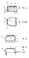
- FIGS. 4a and 4b show a device according to the prior art Technology shown using the example of a bidirectional converter.
- the Plastic encapsulation 10 has two openings 3a, 3b.
- a bidirectional converter used so that the acoustic inputs of which lie behind the openings 3a, 3b come.
- the acoustic inputs are with a self-adhesive membrane 4 covered before inserting the transducer into the plastic encapsulation 10 was applied to the converter.
- a corresponding one Membrane blank 4 with areas 4a and 4b to cover the acoustic inputs against the openings 3a and 3b is in Figure 4b shown as an example.
- Such plastic encapsulations have in the telecommunications sector usually dimensions in the millimeter range and are e.g. about 6 to 8 mm wide or deep and about 5 to 6 mm high.
- the openings can be round or angular, e.g. with a Diameter of 3.5 mm or an edge length of 2 mm x 2.8 mm.
- transducer is problematic in several ways.
- the size of acoustic transducers is particularly in the telecommunications area, as indicated above, on the order of only a few millimeters with a further decreasing tendency.
- a targeted one Attaching the membrane is difficult, complex and corresponding expensive.
- the prepared acoustic Transducers are then inserted into the plastic encapsulation, which, as described above, with their internal dimensions exactly match the external dimensions of the acoustic transducer is matched.
- the object of the present invention is therefore an encapsulated acoustic transducer with acoustically transparent friction element for Installation in a housing, in particular a telecommunications device to create which without much effort and in a reliable manner can be produced.
- connection of the acoustically transparent friction element Surface textile or a membrane, with the plastic encapsulation according to the invention can either be positive or non-positive.
- a snap connection is a good fit, the snap element directly attached to the plastic encapsulation, which is usually is injection molded, can be injected. In this Trap only needs the friction element in front of the sound pressure opening to be placed and pinched by means of a snap connection. On unintentional displacement of the friction element when inserting the acoustic transducer is therefore excluded, and is accordingly the attachment of the friction element compared much less critical by sticking the membrane directly onto the acoustic Converter.
- a plastic encapsulation according to the invention is preferred which is the acoustically transparent friction element during manufacture the plastic encapsulation by "extrusion coating” or “injection molding” is fixed.
- This is also a positive connection of the friction element with the plastic encapsulation.
- injection molding the positive connection is generated in that the plastic material the plastic encapsulation in pores and roughness at least intervenes from partial areas of the textile or membrane surface, while the opposite surface remains free of plastic. It it has been found that this positive connection is complete is sufficient. However, an even more stable connection can be achieved if the friction element is continuous in its edge area from one friction element surface to an opposite one Friction element surface is "overmolded” with plastic material.
- a frictional connection of the friction element with the plastic encapsulation is, for example, by adhesive forces using adhesive possible.
- Plastic encapsulations 10 according to the invention are shown in FIGS. 1 to 3 shown for acoustic transducers that are similar or similar to installation in a housing used for example a telecommunications device become.
- the plastic encapsulations 10 define by their Wall 1 a receiving space 2 for receiving only in Figure 1a exemplary acoustic transducer 20.
- sound pressure openings 3 or 3a and 3b are provided through which the sound from the environment to the acoustic input (s) of the acoustic transducer 20 provided in the receiving space 2 can reach.
- a single sound pressure opening 3 is sufficient, while in the case of a bidirectional one Transducer provided two sound pressure openings 3a and 3b are for the aforementioned reasons and as shown in Figure 1a are preferably aligned at right angles to each other.
- the sound pressure openings are each by an acoustically transparent friction element locked; this is preferably a textile fabric or a membrane that allows the sound pressure to pass, but it does due to the acoustic impedance inherent in the friction element influenced at the same time.
- versions are also conceivable for which an opening is formed without a friction element.
- Embodiments can include the openings in acoustic impedance different (e.g. 100 and 500 ohms) or the same friction elements to be introverted.
- the acoustically transparent friction elements 4 and 4a, 4b are in the in the embodiments shown in Figures 1 and 2 of the Wall 3 enclosed that the wall material continuously from an upper side of the friction element to the correspondingly opposite one Back of the friction element extends. This becomes procedural achieved by the friction element into a shape for Injection molding of the plastic encapsulation 10 is inserted before the Injection molding begins. The friction element 4 is then at Injection molded so that they are firm and form-fitting with the Wall 1 is connected.
- Figure 1 is a plastic encapsulation 10 for a bidirectional Shows transducer 20 in two mutually perpendicular cross sections
- 2 shows a plastic encapsulation 10 for an omnidirectional Also with only one acoustically transparent friction element 4 in cross section.
- the embodiment shown in FIG. 2 is a closure cover 5 above Film hinge 6 molded directly, so that the plastic encapsulation can easily be closed by the cover 5 is snapped behind the nose 7.
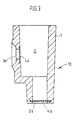
- FIG. 3 shows a further exemplary embodiment of a plastic encapsulation 10 according to the present invention.
- acoustically transparent friction element 4b corresponding to that previously described embodiments according to Figure 1 and Figure 2 with Plastic material of the wall 1 "overmolded” is the friction element 4a only "molded". Also acts in the case of spraying it is a positive connection between the friction element 4a and the wall 1, since the plastic material in the pores and surface roughness of the friction element 4a in the injection molding process penetrates and forms an anchor.
- the acoustically transparent friction element can also be used as an alternative can be fixed in the wall by a snap lock, similar to that in Figure 2 shown in connection with the cap 5 Snap lock, or directly on the surface of the wall 1 can be glued on.
- Porous foils or membranes are therefore particularly suitable made of sintered or unsintered synthetic polymers such as Example polypropylene, polyester, polyamide, polyether, polytetrafluoroethylene (PTFE), polysulfone, ethylene-tetrafluoroethylene copolymer, fluorinated ethylene propylene (FEP) and tetrafluoroethylene / perfluoro (propyl vinyl) ether copolymer (PFA).
- the fluoropolymers mentioned are because of their processing properties, temperature resistance and chemical inertness preferred.
- Particularly preferred become porous membranes made of polytetrafluoroethylene. These can come from contain dark pigments or dyes for aesthetic reasons.
- Porous polytetrafluoroethylene films suitable for use with the invention are suitable, can be prepared by known methods by, for example, stretching or drawing processes, paper manufacturing processes, by procedures in which filler materials in the PTFE resin is stored and then removed to form a leave porous structure, or by powder sintering processes.
- the knots and Fibrils define an internal structure with a three-dimensional one Network of interconnected passages and culverts, which are perpendicular from one surface to the other and laterally from extend one to the other edge through the membrane.
- the porous PTFE film should have a thickness in the range of 0.5 to 1000 ⁇ m, preferably in the range from 5 to 100 ⁇ m, a porosity in the range from 20 to 98%, preferably in the range from 80 to 90%, an air permeability from 0.05 to 30 Gurley seconds, preferably 0.5 to 30 Gurley seconds, and a nominal pore size in the range of 0.05 to Have 50 microns, preferably in the range of 3 to 20 microns.
- a textile fabric can also be used appropriate properties are used.
- a textile fabric fabrics knitted fabrics, fleeces and microfiber textiles are suitable made of synthetic or natural material.
- the friction element on at least one carrier material such as a fleece, a fabric, a knitted fabric, a perforated plate, a grid or non-woven layers made of different plastic materials or organic materials upset.
- a carrier material made of cellulose is preferred.
- the thickness of one preferred carrier material is in the range from 40 to 1000 ⁇ m, preferably 50 to 200 microns.
- the acoustically transparent friction elements usually have a lot thin structures to meet the following characteristics. you Acoustic resistance should be in the range of 0 to 10,000 ohms lie and the sound pressure loss between 0 and 20 dB. As possible for example, laminate is suitable for such applications the applicant available GORE-TEX® laminate EV22209 or EV22210.
- Vulcanizable materials are particularly suitable as the material for the plastic encapsulation Plastics, such as silicones or natural rubber, and thermoplastics, such as polypropylene, polyethylene, Polycarbonates or polyamides and preferably thermoplastic Elastomers such as Santoprene® (available from Montsanto / Italy) or Hytrel® (available from the company DuPont). All of these plastics can be used in the so-called insert Molding use injection molding process, which is the essential The advantage is that the injection molding of the plastic encapsulation and its connection with the acoustically transparent friction elements in one Operation is possible. In particular, the thermoplastic unite Elastomeric properties, in insert molding injection molding to be processed and their elastomer properties preserve.
- the production of the plastic encapsulation according to the invention with an integrated acoustically transparent friction element in insert molding Injection molding is done as follows.
- the friction element will first fixed in an injection mold. It can do that be that the friction element by means of a stamp so against a Wall of the injection molding tool is pressed that now edge areas of the friction element protrude into the injection mold. Then the plastic is injected with the success that the surface of the friction element with the surface of the wall of the pre-sprayed Plastic encapsulation just completes or at least one Side of the friction element remains free of plastic.
- Friction element in such a way to an increase in the injection mold wall pressed that its edge area protrudes laterally beyond this increase, so it is possible to overmold the edge area of the friction element, so that the friction element as shown in Figures 1 and 2, in the Wall 1 is firmly enclosed.
- an opening diameter of e.g. 5 mm is sufficient for a lateral edging of the friction element edge area of about 0.5 mm.
- the production then preferably takes place in accordance with the Sumitomo Electric Industries EP 0 350 813 A2 Limited described using two mobile methods Stamp.
- the acoustic transducer After the plastic encapsulation has been removed from the injection mold can the acoustic transducer easily and without risk of a Detaching the membrane can be used in the plastic encapsulation.
- the plastic encapsulation according to the invention also offers the advantage that in the event that all sound pressure openings are closed with friction elements be the electronic components of the acoustic Converter are fully protected from environmental influences, in particular from dust particles, salts and liquids. This is especially true if the ePTFE membranes are used because they are permeable to air but at the same time waterproof and dustproof.
- the water inlet pressure such friction elements should be over 1 bar.
- the thickness of the membranes was determined with a throat gauge, averaging four different digits.
- Air permeability was determined according to ASTM test procedure D726-84 with a Gurley density meter from W. & L.E. Gurley & Sons determined.
- the water inlet pressure was measured using an ePTFE membrane, which was clamped between two test plates, of which Water pressure is exerted on the membrane via the lower plate can be. Between the top plate and the membrane was a pH paper for the detection of water penetration through the membrane arranged. The pressure was increased in small steps and after each The increase was waited for 10 seconds before the pH paper was examined has been.
- the water inlet pressure is the water pressure at which the pH paper stains due to water breakthrough, the test results be taken from the center of the membrane to influences to avoid damage in the edge area.
Abstract
Description
Die vorliegende Erfindung betrifft eine Kunststoffkapselung für einen akustischen Wandler sowie einen gekapselten akustischen Wandler zum Einbau in ein Gehäuse insbesondere einer Telekommunikationseinrichtung und ein Verfahren zur Herstellung eines solchen gekapselten akustischen Wandlers.The present invention relates to a plastic encapsulation for one acoustic transducer and an encapsulated acoustic transducer for Installation in a housing, in particular a telecommunications device and a method of making such an encapsulated acoustic Converter.
Akustische Wandler wie Mikrophone, Lautsprecher und dergleichen werden häufig in Kunststofformteile eingepreßt oder montiert, um dann als Einheit in Gehäuse von z.B. Telekommunikationseinrichrungen eingebaut zu werden. Die Kunststofformteile sind notwendig, um spezielle akustische Leistungsmerkmale der akustischen Wandler, wie Klangqualität, baßlastiger oder höherlastiger Frequenzgang, Hintergrundrauschen, etc. je nach Anwendungszweck zu optimieren. Aus diesem Grund sind die Kunststofformteile üblicherweise aus einem weichen Kunststoff oder Gummi hergestellt und definieren einen Aufnahmeraum für den akustischen Wandler, wobei der Aufnahmeraum so bemessen ist, daß der akustische Wandler exakt in das Kunststofformteil hineinpaßt. Das Kunststofformteil bildet somit eine Kapselung für den akustischen Wandler.Acoustic transducers such as microphones, loudspeakers and the like are often pressed or assembled in plastic moldings and then as a unit in a housing of e.g. Telecommunications equipment installed to become. The plastic moldings are necessary to make special acoustic performance characteristics of the acoustic transducers, such as sound quality, bass-heavy or higher-heavy frequency response, background noise, etc. to optimize depending on the application. For this The reason is that the plastic molded parts are usually made of a soft material Made of plastic or rubber and define a recording space for the acoustic transducer, the recording space being dimensioned in such a way that the acoustic transducer fits exactly into the molded plastic part. The plastic molded part thus forms an encapsulation for the acoustic Converter.
Eine solche Kunststoffkapselung weist eine oder mehrere Schalldrucköffnungen auf, durch die der Schall den oder die akustischen Eingänge des in der Kunststoffkapselung aufgenommenen akustischen Wandlers erreichen kann. Die Anzahl der Schalldrucköffnungen und die Lage des akustischen Wandlers in der Kunststoffkapselung haben wesentlichen Einfluß auf den akustischen Charakter der Vorrichtung. Bei einem Mikrophon mit "unidirektionalem" Charakter ist nur eine Schalldrucköffnung vorgesehen, und der akustische Eingang des Wandlers ist relativ weit von dieser Schalldrucköffnung entfernt, so daß nur gerichteter Schall den Wandler erreicht. Bei einem Mikrophon mit "omnidirektionalem" Charakter hingegen liegt der akustische Eingang des Wandlers nahe an der Schalldrucköffnung, so daß Schall aus unterschiedlichsten Richtungen den akustischen Eingang des Wandlers erreichen kann. Mikrophone mit "bidirektionalem" Charakter haben zwei Eingänge, die vorzugsweise in einem 90° Winkel zueinander angeordnet sind. Damit können Hintergrundgeräusche bzw. ungerichtete Schallanteile eliminiert werden, indem die durch die Schalldrucköffnungen jeweils einfallenden Schalldrücke auf gegenüberliegende Seiten einer als akustischer Wandler wirkenden Membran geleitet werden, so daß sich die ungerichteten Schalldruckpegel der Hintergrundgeräusche gegeneinander aufheben.Such a plastic encapsulation has one or more sound pressure openings through which the sound enters the acoustic input (s) of the acoustic transducer housed in the plastic encapsulation can reach. The number of sound pressure openings and the location of the acoustic transducers in the plastic encapsulation have essential Influence on the acoustic character of the device. With a microphone with "unidirectional" character is only a sound pressure opening provided, and the acoustic input of the transducer is relative far from this sound pressure opening, so that only directed Sound reached the transducer. For a microphone with "omnidirectional" The acoustic input of the transducer, however, is character close to the sound pressure opening, so that sound from different Directions can reach the acoustic input of the transducer. Microphones with a "bidirectional" character have two inputs that are preferably arranged at a 90 ° angle to one another. In order to can eliminate background noise or non-directional sound components by the incident through the sound pressure openings Sound pressures on opposite sides as an acoustic transducer acting membrane are passed so that the undirected Cancel the sound pressure level of the background noise against each other.
Die akustischen Leistungsmerkmale der akustischen Wandler werden jedoch nicht allein durch die Art und Struktur der Kunststoffkapselung bestimmt, sondern darüber hinaus sind auf dem akustischen Wandler selbst separate akustisch transparente Reibungselemente in Form von textilen Flächengebilden oder Membranen angebracht, denen eine akustische Impedanz zukommt. Vielfach sind diese Reibungselemente porös und dadurch luftdurchlässig, um die akustische Impedanz zu erzielen. Das heißt, der Schalldruck erreicht zwar aufgrund der Luftdurchlässigkeit des Reibungselements nachwievor den akustischen Eingang des akustischen Wandlers, jedoch entstehen charakteristische Reibungs- bzw. Schalldruckverluste, so daß mittels dieser akustisch transparenten Reibungselemente gezielt akustische Effekte erreichbar sind. Das akustisch transparente Reibungselement bildet somit zusätzlich zu der Kunststoff-bzw. Gummikapselung ein weiteres, von der Art und Struktur der Kunststoffkapselung unabhängiges Dämpfungselement. Die Eigenschaften eines porösen Dämpfungselements hängen insbesondere ab von Materialdicke. Porosität und Nennporengröße. "Akustisch transparent" heißt in diesem Zusammenhang, daß die Schallenergie durch das Reibungselement um 0 bis 20 dB beeinflußt wird, je nach gewünschter Charakteristik. The acoustic performance characteristics of the acoustic transducers but not just because of the type and structure of the plastic encapsulation determined but beyond are on the acoustic transducer even separate acoustically transparent friction elements in the form of textile fabrics or membranes attached to which an acoustic Impedance comes. These friction elements are often porous and therefore permeable to air to achieve the acoustic impedance. That means that the sound pressure reaches due to the air permeability of the friction element as before the acoustic input of the acoustic transducer, but characteristic friction or Sound pressure losses, so that by means of these acoustically transparent friction elements targeted acoustic effects can be achieved. That acoustically transparent friction element thus forms in addition to the plastic or. Rubber encapsulation another, of the type and structure of the Plastic encapsulation independent damping element. The properties of a porous damping element depend in particular on the material thickness. Porosity and nominal pore size. "Acoustically transparent" means in this connection that the sound energy by the friction element is influenced by 0 to 20 dB, depending on the desired characteristic.
Bisher wurden die akustisch transparenten Reibungselemente unmittelbar auf dem akustischen Wandler, zum Beispiel einem Mikrophon, aufgebracht, zum Beispiel aufgeklebt. Das so vorbereitete Mikrophon wurde dann in die Kunststoffkapselung eingesetzt, um daraufhin als Einheit in einem Gehäuse, zum Beispiel eines mobilen Telefons, an geeigneter Stelle befestigt zu werden.So far, the acoustically transparent friction elements have been immediate applied to the acoustic transducer, for example a microphone, for example glued on. The microphone thus prepared was then inserted into the plastic encapsulation, in order then as a unit in a housing, for example a mobile phone, to a suitable one Spot to be attached.
In den Figuren 4a und 4b ist eine Vorrichtung nach dem Stand der
Technik am Beispiel eines bidirektionalen Wandlers dargestellt. Die
Kunststoffkapselung 10 weist zwei Öffnungen 3a, 3b auf. In der Kunststoffkapselung
10 ist ein bidirektionaler Wandler so eingesetzt, daß
dessen akustische Eingänge hinter den Öffnungen 3a, 3b zu liegen
kommen. Die akustischen Eingänge sind mit einer selbstklebenden Membran
4 abgedeckt, die vor dem Einsetzen des Wandlers in die Kunststoffkapselung
10 auf dem Wandler aufgebracht wurde. Ein entsprechender
Membranzuschnitt 4 mit Bereichen 4a und 4b zur Abdeckung der
akustischen Eingänge gegen die Öffnungen 3a bzw. 3b ist in Figur 4b
exemplarisch dargestellt. Solche Kunststoffkapselungen haben im Telekommunikationsbereich
üblicherweise Abmessungen im Millimeterbereich
und sind z.B. etwa 6 bis 8 mm breit bzw. tief und etwa 5 bis 6
mm hoch. Die Öffnungen können rund oder eckig sein, z.B. mit einem
Durchmesser von 3,5 mm oder einer Kantenlänge von 2 mm x 2,8 mm.4a and 4b show a device according to the prior art
Technology shown using the example of a bidirectional converter. The
Das Anbringen der akustisch transparenten Membran auf dem akustischen Wandler ist jedoch in mehrfacher Hinsicht problematisch. Einerseits liegt die Größe akustischer Wandler insbesondere im Telekommunikationsbereich, wie oben angegeben, in der Größenordnung von nur wenigen Millimetern mit weiter abnehmender Tendenz. Ein gezieltes Anbringen der Membran ist dadurch schwierig, aufwendig und entsprechend kostenintensiv. Andererseits muß der so vorbereitete akustische Wandler anschließend in die Kunststoffkapselung eingesetzt werden, die, wie oben beschrieben, mit ihren Innenmaßen exakt auf die Außenmaße des akustischen Wandlers abgestimmt ist. Beim Einsetzen können daher die aufgeklebten Membrane an Kanten hängenbleiben oder sich reibungsbedingt wieder von dem akustischen Wandler lösen, was insbesondere bei Mikrophonen mit bidirektionalem Verhalten kritisch ist, da bei dieser Ausführungsart beim Einsetzen des Wandlers in die Kunststoffkapselung regelmäßig eine der Membranen an einer Innenwand der Kunststoffkapselung entlanggeschoben werden muß. Im Hinblick auf die Massenfertigung ist ein einfacheres und zuverlässigeres Herstellungsverfahren wünschenswert, das eine gleichbleibend hochwertige Qualität gewährleistet.Attaching the acoustically transparent membrane to the acoustic However, transducer is problematic in several ways. On the one hand the size of acoustic transducers is particularly in the telecommunications area, as indicated above, on the order of only a few millimeters with a further decreasing tendency. A targeted one Attaching the membrane is difficult, complex and corresponding expensive. On the other hand, the prepared acoustic Transducers are then inserted into the plastic encapsulation, which, as described above, with their internal dimensions exactly match the external dimensions of the acoustic transducer is matched. When inserting therefore the glued membrane stuck to edges or itself due to friction, detach from the acoustic transducer, which in particular is critical for microphones with bidirectional behavior, because in this embodiment when the transducer is inserted into the plastic encapsulation regularly one of the membranes on an inner wall of the Plastic encapsulation must be pushed along. In terms of Mass production is a simpler and more reliable manufacturing process desirable that a consistently high quality guaranteed.
Aufgabe der vorliegenden Erfindung ist es daher, einen gekapselten akustischen Wandler mit akustisch transparentem Reibungselement zum Einbau in ein Gehäuse insbesondere einer Telekommunikationseinrichtung zu schaffen, welcher ohne viel Aufwand und in zuverlässiger Weise herstellbar ist.The object of the present invention is therefore an encapsulated acoustic transducer with acoustically transparent friction element for Installation in a housing, in particular a telecommunications device to create which without much effort and in a reliable manner can be produced.
Diese Aufgabe wird erfindungsgemäß durch die Merkmale der unabhängigen Ansprüche gelöst. Der Kern der Lösung ist darin zu sehen, daß das akustisch transparente Reibungselement nicht direkt auf dem akustischen Wandler sondern in bzw. an der Schalldrucköffnung der Kunststoffkapselung befestigt wird, indem es vorzugsweise beim Spritzen der Kunststoffkapselung angespritzt oder umspritzt wird.This object is achieved by the features of the independent Claims resolved. The essence of the solution is to see that the acoustically transparent friction element is not directly on the acoustic transducer but in or at the sound pressure opening of the Plastic encapsulation is attached, preferably by the Injection of the plastic encapsulation is injected or encapsulated.
Die Verbindung des akustisch transparenten Reibungselements, ein Flächentextil oder eine Membran, mit der erfindungsgemäßen Kunststoffkapselung kann entweder formschlüssig oder kraftschlüssig erfolgen. Als formschlüssige Verbindung bietet sich eine Schnappverbindung an, wobei das Schnappelement direkt an die Kunststoffkapselung, die üblicherweise spritzgegossen wird, angespritzt werden kann. In diesem Falle braucht das Reibungselement lediglich vor die Schalldrucköffnung plaziert und mittels Schnappverbindung eingeklemmt zu werden. Ein unbeabsichtiges Verschieben des Reibungselements beim Einsetzen des akustischen Wandlers ist somit ausgeschlossen, und dementsprechend ist auch das Anbringen des Reibungselements wesentlich unkritischer verglichen mit dem Aufkleben der Membran direkt auf dem akustischen Wandler.The connection of the acoustically transparent friction element Surface textile or a membrane, with the plastic encapsulation according to the invention can either be positive or non-positive. A snap connection is a good fit, the snap element directly attached to the plastic encapsulation, which is usually is injection molded, can be injected. In this Trap only needs the friction element in front of the sound pressure opening to be placed and pinched by means of a snap connection. On unintentional displacement of the friction element when inserting the acoustic transducer is therefore excluded, and is accordingly the attachment of the friction element compared much less critical by sticking the membrane directly onto the acoustic Converter.
Bevorzugt wird jedoch eine erfindungsgemäße Kunststoffkapselung, bei der das akustisch transparente Reibungselement bereits bei der Herstellung der Kunststoffkapselung durch "Umspritzen" bzw. "Anspritzen" fixiert wird. Auch dabei handelt es sich um eine formschlüssige Verbindung des Reibungselements mit der Kunststoffkapselung. Im Falle des "Anspritzens" wird der Formschluß dadurch erzeugt, daß das Kunststoffmaterial der Kunststoffkapselung in Poren und Rauhigkeiten zumindest von Teilbereichen der Textil- oder Membranoberfläche eingreift, während die gegenüberliegende Oberfläche frei von Kunststoff bleibt. Es hat sich herausgestellt, daß diese formschlüssige Verbindung völlig ausreichend ist. Eine noch stabilere Verbindung läßt sich jedoch erreichen, wenn das Reibungselement in seinem Randbereich kontinuierlich von einer Reibungselementoberfläche zu einer gegenüberliegenden Reibungselementoberfläche mit Kunststoffmaterial "umspritzt" wird.However, a plastic encapsulation according to the invention is preferred which is the acoustically transparent friction element during manufacture the plastic encapsulation by "extrusion coating" or "injection molding" is fixed. This is also a positive connection of the friction element with the plastic encapsulation. In the case of "Injection molding" the positive connection is generated in that the plastic material the plastic encapsulation in pores and roughness at least intervenes from partial areas of the textile or membrane surface, while the opposite surface remains free of plastic. It it has been found that this positive connection is complete is sufficient. However, an even more stable connection can be achieved if the friction element is continuous in its edge area from one friction element surface to an opposite one Friction element surface is "overmolded" with plastic material.
Eine kraftschlüssige Verbindung des Reibungselements mit der Kunststoffkapselung ist zum Beispiel durch Adhäsionskräfte mittels Klebstoff möglich.A frictional connection of the friction element with the plastic encapsulation is, for example, by adhesive forces using adhesive possible.
Weitere vorteilhafte Ausgestaltungen sind in den Unteransprüchen definiert und ergeben sich aus der nachfolgenden Beschreibung einer bevorzugten Ausführungsform.Further advantageous refinements are defined in the subclaims and result from the following description of a preferred Embodiment.
In den Figuren bezeichnen:
In den Figuren sind gleiche Bauteile unterschiedlicher Ausführungsformen mit identischen Bezugsziffern bezeichnet.The same components in different embodiments are shown in the figures designated with identical reference numbers.
In den Figuren 1 bis 3 sind erfindungsgemäße Kunststoffkapselungen 10
für akustische Wandler dargestellt, die so oder ähnlich zum Einbau in
ein Gehäuse zum Beispiel einer Telekommunikationseinrichtung verwendet
werden. Die Kunststoffkapselungen 10 definieren durch ihre
Wandung 1 einen Aufnahmeraum 2 zur Aufnahme eines nur in Figur 1a
exemplarisch dargestellten akustischen Wandlers 20. In den Wandungen
1 sind Schalldrucköffnungen 3 bzw. 3a und 3b vorgesehen, durch die
der Schall aus der Umgebung zu dem bzw. den akustischen Eingängen
des in dem Aufnahmeraum 2 vorgesehenen akustischen Wandlers 20
gelangen können. Im Falle eines omni- oder unidirektionalen Wandlers
genügt eine einzige Schalldrucköffnung 3, während im Falle eines bidirektionalen
Wandlers zwei Schalldrucköffnungen 3a und 3b vorgesehen
sind, die aus den vorgenannten Gründen und wie in Figur 1a gezeigt
vorzugsweise rechtwinklig zueinander ausgerichtet sind. Die Schalldrucköffnungen
sind jeweils durch ein akustisch transparentes Reibungselement
verschlossen; das ist vorzugsweise ein textiles Flächengebilde
oder eine Membran, die den Schalldruck zwar durchläßt, ihn jedoch
aufgrund der dem Reibungselement eigenen akustischen Impedanz
gleichzeitig beeinflußt. Es sind jedoch auch Ausführungen denkbar, bei
denen eine Öffnung ohne Reibungselement ausgebildet ist. Bei anderen
Ausführungsformen können die Öffnungen mit in der akustischen Impedanz
verschiedenen (z.B. 100 und 500 Ohm) oder gleichen Reibungselementen
verschlossen sein.
Die akustisch transparenten Reibungselemente 4 bzw. 4a, 4b sind in den
in den Figuren 1 und 2 dargestellten Ausführungsformen so von der
Wandung 3 umschlossen, daß sich das Wandungsmaterial kontinuierlich
von einer Oberseite des Reibungselements auf die entsprechend gegenüberliegende
Rückseite des Reibungselements erstreckt. Dies wird verfahrensmäßig
erreicht, indem das Reibungselement in eine Form zum
Spritzgießen der Kunststoffkapselung 10 eingelegt wird, bevor der
Spritzgußvorgang beginnt. Das Reibungselement 4 wird sodann beim
Einspritzvorgang derart umspritzt, daß sie fest und formschlüssig mit der
Wandung 1 verbunden ist.The acoustically
Während Figur 1 eine Kunststoffkapselung 10 für einen bidirektionalen
Wandler 20 in zwei senkrecht zueinander liegenden Querschnitten zeigt,
zeigt Figur 2 eine Kunststoffkapselung 10 für einen omnidirektionalen
Wandler mit nur einem akustisch transparenten Reibungselement 4 ebenfalls
im Querschnitt. An die Kunststoffkapselung 10 gemäß der in Figur
2 dargestellten Ausführungsform ist ein Verschlußdeckel 5 über ein
Filmscharnier 6 unmittelbar angespritzt, so daß die Kunststoffkapselung
problemlos verschlossen werden kann, indem der Verschlußdeckel 5
hinter die Nase 7 eingerastet wird.While Figure 1 is a
Figur 3 zeigt eine weitere beispielhafte Ausführungsform einer Kunststoffkapselung
10 gemäß der vorliegenden Erfindung. Während das
akustisch transparente Reibungselement 4b entsprechend den zuvor
beschriebenen Ausführungsformen gemäß Figur 1 und Figur 2 mit
Kunststoffmaterial der Wandung 1 "umspritzt" ist, ist das Reibungselement
4a lediglich "angespritzt". Auch im Falle des Anspritzens handelt
es sich um eine formschlüssige Verbindung zwischen dem Reibungselement
4a und der Wandung 1, da das Kunststoffmaterial in die Poren
und Oberflächenrauhigkeiten des Reibungselements 4a beim Spritzgußvorgang
eindringt und eine Verankerung bildet.FIG. 3 shows a further exemplary embodiment of a
Das akustisch transparente Reibungselement kann jedoch auch alternativ
durch Schnappverschluß in der Wandung fixiert werden, ähnlich dem in
Figur 2 in Verbindung mit dem Verschlußdeckel 5 dargestellten
Schnappverschluß, oder aber auch direkt auf die Oberfläche der Wandung
1 aufgeklebt werden.However, the acoustically transparent friction element can also be used as an alternative
can be fixed in the wall by a snap lock, similar to that in
Figure 2 shown in connection with the
Je nach Anforderung kann es auch sinnvoll sein, lediglich eine von mehreren Öffnungen mit einem akustisch transparenten Reibungselement zu verschließen.Depending on the requirements, it may also be useful to only use one of several openings with an acoustically transparent friction element to close.
Als akustisch transparentes Reibungselement eignet sich insbesondere jedes poröse Material, das den Schalldruck zwar durchläßt, ihn aber in charakteristischer Weise aufgrund seiner akustischen Impedanz beeinflußt. Geeignet sind daher insbesondere poröse Folien oder Membranen aus gesinterten oder ungesinterten synthetischen Polymeren wie zum Beispiel Polypropylen, Polyester, Polyamid, Polyether, Polytetrafluorethylen (PTFE), Polysulfon, Ethylen-Tetrafluorethylen-Copolymer, fluoriertes Ethylenpropylen (FEP) und Tetrafluorethylen-/Perfluor(Propylvinyl)-Ether-Copolymer (PFA). Die genannten Fluorpolymere werden wegen ihrer Verarbeitungseigenschaften, Temperaturbeständigkeit und chemischen Inertheit bevorzugt. Besonders bevorzugt werden poröse Membranen aus Polytetrafluorethylen. Diese können aus ästhetischen Gründen dunkle Pigmente oder Farbstoffe enthalten.Particularly suitable as an acoustically transparent friction element any porous material that allows the sound pressure to pass through but in characteristically influenced due to its acoustic impedance. Porous foils or membranes are therefore particularly suitable made of sintered or unsintered synthetic polymers such as Example polypropylene, polyester, polyamide, polyether, polytetrafluoroethylene (PTFE), polysulfone, ethylene-tetrafluoroethylene copolymer, fluorinated ethylene propylene (FEP) and tetrafluoroethylene / perfluoro (propyl vinyl) ether copolymer (PFA). The fluoropolymers mentioned are because of their processing properties, temperature resistance and chemical inertness preferred. Particularly preferred become porous membranes made of polytetrafluoroethylene. These can come from contain dark pigments or dyes for aesthetic reasons.
Poröse Polytetrafluorethylenfolien, die zur Verwendung mit der Erfindung geeignet sind, können nach bekannten Verfahren hergestellt werden, zum Beispiel durch Dehn- oder Ziehverfahren, durch Papierhersteilungsverfahren, durch Verfahren in denen Füllmaterialien in das PTFE-Harz eingelagert und anschließend entfernt werden, um eine poröse Struktur zu hinterlassen, oder durch Pulversinterprozesse. Vorzugsweise wird als poröses PTFE eine poröse expandierte PTFE-Folie mit einer aus miteinander verbundenen Knoten und Fibrillen bestehenden Struktur verwendet, wie es in den US-Patenten Nr. 3,953,566 und 4,187,390 beschrieben ist, die das bevorzugte Material und die bevorzugten Verfahren zur Herstellung der Folie beschreiben. Die Knoten und Fibrillen definieren eine innere Struktur mit einem dreidimensionalen Netzwerk aus miteinander verbundenen Durchgängen und Durchlässen, die sich senkrecht von einer zur anderen Oberfläche und seitlich von einer zur anderen Kante durch die Membran hindurch erstrecken. Die poröse PTFE-Folie sollte eine Dicke im Bereich von 0,5 bis 1000 µm, vorzugsweise im Bereich von 5 bis 100 µm eine Porosität im Bereich von 20 bis 98%, vorzugsweise im Bereich von 80 bis 90%, eine Luftdurchlässigkeit von 0,05 bis 30 Gurley-Sekunden, vorzugsweise 0,5 bis 30 Gurley Sekunden, und eine Nennporengröße im Bereich von 0,05 bis 50 µm, vorzugsweise im Bereich von 3 bis 20 µm aufweisen.Porous polytetrafluoroethylene films suitable for use with the invention are suitable, can be prepared by known methods by, for example, stretching or drawing processes, paper manufacturing processes, by procedures in which filler materials in the PTFE resin is stored and then removed to form a leave porous structure, or by powder sintering processes. Preferably becomes a porous expanded PTFE film as porous PTFE with one consisting of interconnected nodes and fibrils Structure used as in U.S. Patent Nos. 3,953,566 and 4,187,390, which is the preferred material and preferred Describe the process for making the film. The knots and Fibrils define an internal structure with a three-dimensional one Network of interconnected passages and culverts, which are perpendicular from one surface to the other and laterally from extend one to the other edge through the membrane. The porous PTFE film should have a thickness in the range of 0.5 to 1000 µm, preferably in the range from 5 to 100 μm, a porosity in the range from 20 to 98%, preferably in the range from 80 to 90%, an air permeability from 0.05 to 30 Gurley seconds, preferably 0.5 to 30 Gurley seconds, and a nominal pore size in the range of 0.05 to Have 50 microns, preferably in the range of 3 to 20 microns.
Anstelle einer Membran kann aber auch ein textiles Flächengebilde mit entsprechenden Eigenschaften eingesetzt werden. Als textiles Flächengebilde eignen sich Gewebe, Gewirke, Vliese und Mikrofasertextilien aus synthetischem oder natürlichem Material.Instead of a membrane, a textile fabric can also be used appropriate properties are used. As a textile fabric fabrics, knitted fabrics, fleeces and microfiber textiles are suitable made of synthetic or natural material.
Um die Stabilität der porösen Strukturen zu verbessern, wird das Reibungselement auf mindestens ein Trägermaterial wie ein Vlies, ein Gewebe, ein Gewirke, eine Lochplatte, ein Gitter oder nicht-gewebte Lagen aus unterschiedlichen Kunststoffmaterialien oder organischen Materialien aufgebracht. Als Trägermaterial eignet sich Polyester, Polyamid, Aramid oder ein Fluorpolymer, wobei nicht-gewebtes Polyester-Material mit dunkler Färbung bevorzugt wird. Ebenfalls besonders geeignet ist ein Trägermaterial aus Zellulose. Die Dicke eines solchen bevorzugten Trägermaterials liegt im Bereich von 40 bis 1000 µm, vorzugsweise 50 bis 200 µm.In order to improve the stability of the porous structures, the friction element on at least one carrier material such as a fleece, a fabric, a knitted fabric, a perforated plate, a grid or non-woven layers made of different plastic materials or organic materials upset. Polyester, polyamide, Aramid or a fluoropolymer, using non-woven polyester material with a dark color is preferred. Also special a carrier material made of cellulose is suitable. The thickness of one preferred carrier material is in the range from 40 to 1000 μm, preferably 50 to 200 microns.
Die akustisch transparenten Reibungselemente weisen üblicherweise sehr dünne Strukturen auf, um folgende Charakteristika zu erfüllen. Ihr akustischer Widerstandswert soll im Bereich von 0 bis 10000 Ohm liegen und der Schalldruckverlust zwischen 0 und 20 dB. Als mögliches Laminat für derartige Anwendungen eignet sich zum Beispiel das über die Anmelderin erhältliche GORE-TEX®-Laminat EV22209 oder EV22210.The acoustically transparent friction elements usually have a lot thin structures to meet the following characteristics. you Acoustic resistance should be in the range of 0 to 10,000 ohms lie and the sound pressure loss between 0 and 20 dB. As possible For example, laminate is suitable for such applications the applicant available GORE-TEX® laminate EV22209 or EV22210.
Als Material für die Kunststoffkapselung eignen sich insbesondere vulkanisierbare Kunststoffe, wie zum Beispiel Silikone oder Naturkautschuk, und thermoplastische Kunststoffe, wie zum Beispiel Polypropylen, Polyethylen, Polycarbonate oder Polyamide sowie vorzugsweise thermoplastische Elastomere wie zum Beispiel Santoprene® (erhältlich über die Firma Montsanto/Italien) oder Hytrel® (erhältlich über die Firma DuPont). Alle diese Kunststoffe lassen sich im sogenannten Insert Moulding Spritzgußverfahren verwenden, welches den wesentlichen Vorteil bietet, daß das Spritzen der Kunststoffkapselung und ihre Verbindung mit den akustisch transparenten Reibungselementen in einem Arbeitsgang möglich ist. Insbesondere vereinen die thermoplastischen Elastomere die Eigenschaften, im Insert Moulding Spritzgußverfahren verarbeitet werden zu können und dabei ihre Elastomereigenschaften bewahren.Vulcanizable materials are particularly suitable as the material for the plastic encapsulation Plastics, such as silicones or natural rubber, and thermoplastics, such as polypropylene, polyethylene, Polycarbonates or polyamides and preferably thermoplastic Elastomers such as Santoprene® (available from Montsanto / Italy) or Hytrel® (available from the company DuPont). All of these plastics can be used in the so-called insert Molding use injection molding process, which is the essential The advantage is that the injection molding of the plastic encapsulation and its connection with the acoustically transparent friction elements in one Operation is possible. In particular, the thermoplastic unite Elastomeric properties, in insert molding injection molding to be processed and their elastomer properties preserve.
Die Herstellung der erfindungsgemäßen Kunststoffkapselung mit integriertem akustisch transparenten Reibungselement im Insert Moulding Spritzgußverfahren erfolgt folgendermaßen. Das Reibungselement wird zunächst in einem Spritzgußwerkzeug fixiert. Das kann dadurch bewirkt werden, daß das Reibungselement mittels einem Stempel so gegen eine Wandung des Spritzgußwerkzeugs gedrückt wird, daß nunmehr Randbereiche des Reibungselements in die Spritzgußform hineinragen. Dann erfolgt das Anspritzen des Kunststoffs mit dem Erfolg, daß die Oberfläche des Reibungselements mit der Oberfläche der Wandung der fertiggespritzten Kunststoffkapselung eben abschließt oder zumindest eine Seite des Reibungselements frei von Kunststoff bleibt. Wird dagegen das Reibungselement derart auf eine Erhöhung der Spritzgußformwandung gepreßt, daß sein Randbereich über diese Erhöhung seitlich übersteht, so ist es möglich, den Randbereich des Reibungselements zu umspritzen, so daß das Reibungselement wie in den Figuren 1 und 2 dargestellt, in der Wandung 1 fest eingefaßt ist. Bei einem Öffnungsdurchmesser von z.B. 5 mm genügt eine seitliche Einfassung des Reibungselementrandbereichs von etwa 0,5 mm. In besonderen Fällen kann es notwendig sein, das Reibungselement zwischen zwei Stempeln so zu fixieren, daß das Reibungselement beim Einspritzvorgang über die Stempel seitlich so hinausragt, daß der Randbereich des Reibungselements mit Spritzgußmaterial umspritzt werden kann. Die Herstellung erfolgt dann vorzugsweise gemäß dem in der EP 0 350 813 A2 von Sumitomo Electric Industries Limited beschriebenen Verfahren unter Verwendung zweier beweglicher Stempel.The production of the plastic encapsulation according to the invention with an integrated acoustically transparent friction element in insert molding Injection molding is done as follows. The friction element will first fixed in an injection mold. It can do that be that the friction element by means of a stamp so against a Wall of the injection molding tool is pressed that now edge areas of the friction element protrude into the injection mold. Then the plastic is injected with the success that the surface of the friction element with the surface of the wall of the pre-sprayed Plastic encapsulation just completes or at least one Side of the friction element remains free of plastic. But it will Friction element in such a way to an increase in the injection mold wall pressed that its edge area protrudes laterally beyond this increase, so it is possible to overmold the edge area of the friction element, so that the friction element as shown in Figures 1 and 2, in the Wall 1 is firmly enclosed. With an opening diameter of e.g. 5 mm is sufficient for a lateral edging of the friction element edge area of about 0.5 mm. In special cases, it may be necessary Fix the friction element between two stamps so that the friction element protrudes laterally beyond the punches during the injection process, that the edge area of the friction element with injection molding material can be encapsulated. The production then preferably takes place in accordance with the Sumitomo Electric Industries EP 0 350 813 A2 Limited described using two mobile methods Stamp.
Nach dem Entformen der Kunststoffkapselung aus dem Spritzgußwerkzeug kann der akustische Wandler problemlos und ohne Gefahr eines Ablösens der Membran in die Kunststoffkapselung eingesetzt werden.After the plastic encapsulation has been removed from the injection mold can the acoustic transducer easily and without risk of a Detaching the membrane can be used in the plastic encapsulation.
Die Herstellung der Kunststoffkapselung mittels dem Insert Moulding Spritzgußverfahren bietet dabei den weiteren Vorteil, daß das Reibungselement absolut exakt an der gewünschten Stelle angeordnet ist, was bei den bekannten Verfahren problematisch ist.The production of the plastic encapsulation by means of insert molding Injection molding offers the further advantage that the friction element is absolutely exactly at the desired location, which is the case with the known method is problematic.
Die erfindungsgemäße Kunststoffkapselung bietet außerdem den Vorteil, daß im Falle, daß alle Schalldrucköffnungen mit Reibungselementen verschlossen werden, die elektronischen Komponenten des akustischen Wandlers vor Umwelteinflüssen vollständig geschützt sind, insbesondere vor Staubpartikeln, Salzen und Flüssigkeiten. Dies gilt insbesondere, wenn die ePTFE-Membranen verwendet werden, denn diese sind zwar luftdurchlässig aber gleichzeitig wasserdicht und staubdicht. Der Wassereintrittsdruck solcher Reibungselemente sollte über 1 bar liegen.The plastic encapsulation according to the invention also offers the advantage that in the event that all sound pressure openings are closed with friction elements be the electronic components of the acoustic Converter are fully protected from environmental influences, in particular from dust particles, salts and liquids. This is especially true if the ePTFE membranes are used because they are permeable to air but at the same time waterproof and dustproof. The water inlet pressure such friction elements should be over 1 bar.
Die Dicke der Membranen wurde mit einer Rachenlehre bestimmt, wobei ein Mittelwert von vier verschiedenen Stellen gebildet wurde.The thickness of the membranes was determined with a throat gauge, averaging four different digits.
Die Porosität ergibt sich nach der Formel
Die Luftdurchlässigkeit wurde nach dem ASTM Testverfahren D726-84 mit einem Gurley Dichtemeßgerät von W. & L.E. Gurley & Sons bestimmt.Air permeability was determined according to ASTM test procedure D726-84 with a Gurley density meter from W. & L.E. Gurley & Sons determined.
Der Wassereintrittsdruck wurde anhand einer ePTFE-Membran gemessen, die zwischen zwei Testplatten eingespannt wurde, von denen über die untere Platte ein Wasserdruck auf die Membran ausgeübt werden kann. Zwischen der oberen Platte und der Membran wurde ein pH-Papier zum Nachweis des Wasserdurchtritts durch die Membran angeordnet. Der Druck wurde in kleinen Stufen erhöht und nach jeder Erhöhung wurde 10 Sekunden abgewartet, bevor das pH-Papier untersucht wurde. Der Wassereintrittsdruck ist der Wasserdruck, bei dem sich das pH-Papier wegen Wasserdurchbruchs färbt, wobei die Testergebnisse von der Mitte der Membran genommen werden, um Einflüsse von Beschädigungen im Randbereich zu vermeiden.The water inlet pressure was measured using an ePTFE membrane, which was clamped between two test plates, of which Water pressure is exerted on the membrane via the lower plate can be. Between the top plate and the membrane was a pH paper for the detection of water penetration through the membrane arranged. The pressure was increased in small steps and after each The increase was waited for 10 seconds before the pH paper was examined has been. The water inlet pressure is the water pressure at which the pH paper stains due to water breakthrough, the test results be taken from the center of the membrane to influences to avoid damage in the edge area.
Claims (29)
Applications Claiming Priority (2)
| Application Number | Priority Date | Filing Date | Title |
|---|---|---|---|
| DE1998131771 DE19831771C2 (en) | 1998-07-15 | 1998-07-15 | Plastic encapsulation for a transducer and encapsulated acoustic transducer |
| DE19831771 | 1998-07-15 |
Publications (2)
| Publication Number | Publication Date |
|---|---|
| EP0973355A2 true EP0973355A2 (en) | 2000-01-19 |
| EP0973355A3 EP0973355A3 (en) | 2005-02-09 |
Family
ID=7874144
Family Applications (1)
| Application Number | Title | Priority Date | Filing Date |
|---|---|---|---|
| EP99113735A Withdrawn EP0973355A3 (en) | 1998-07-15 | 1999-07-13 | Plastic encapsulation for an acoustic transducer |
Country Status (3)
| Country | Link |
|---|---|
| EP (1) | EP0973355A3 (en) |
| JP (1) | JP2000151782A (en) |
| DE (1) | DE19831771C2 (en) |
Cited By (3)
| Publication number | Priority date | Publication date | Assignee | Title |
|---|---|---|---|---|
| FR2789256A1 (en) * | 1999-01-28 | 2000-08-04 | Samsung Electro Mech | Mfr. process for microphone includes fastening stirrup, magnet and plate together with moulding resin |
| GB2372397B (en) * | 2001-02-20 | 2004-10-06 | Mitel Corp | Microphone gasket with integrated acoustic resistance |
| CN107277734A (en) * | 2017-06-21 | 2017-10-20 | 歌尔股份有限公司 | Flexible net injection mold |
Families Citing this family (9)
| Publication number | Priority date | Publication date | Assignee | Title |
|---|---|---|---|---|
| DE10043201C1 (en) * | 2000-09-01 | 2002-01-24 | Siemens Audiologische Technik | Miniature electroacoustic transducer for telephone handset or hearing aid has outer encapsulation housing filled with gas at reduced pressure |
| DE10053286C2 (en) * | 2000-10-27 | 2002-10-17 | Fhf Funke & Huster Fernsig Gmb | Telephone receivers, in particular for telephone sets on telephone columns |
| JP3908624B2 (en) * | 2002-07-25 | 2007-04-25 | シチズン電子株式会社 | Electroacoustic transducer |
| DE102004027111B4 (en) * | 2004-06-03 | 2008-01-10 | Sennheiser Electronic Gmbh & Co. Kg | Acoustic transducer |
| JP2006203468A (en) * | 2005-01-19 | 2006-08-03 | Nippon Denon Kk | Drip-proof type unidirectional microphone unit |
| JP4787947B2 (en) * | 2005-11-04 | 2011-10-05 | 出光興産株式会社 | Explosion-proof acoustic sensor |
| JP4535395B2 (en) * | 2006-12-19 | 2010-09-01 | 岩崎通信機株式会社 | Transmitter |
| DE102007061310A1 (en) * | 2007-12-19 | 2009-06-25 | Siemens Medical Instruments Pte. Ltd. | Electroacoustic miniature transducer with holding means for installation in a hearing aid |
| JP5080346B2 (en) * | 2008-04-24 | 2012-11-21 | 株式会社オーディオテクニカ | Ribbon microphone unit and ribbon microphone |
Citations (6)
| Publication number | Priority date | Publication date | Assignee | Title |
|---|---|---|---|---|
| GB900681A (en) * | 1957-08-05 | 1962-07-11 | Ca Nat Research Council | Improved earphone |
| US4349082A (en) * | 1980-12-22 | 1982-09-14 | Unitron Industries Limited | Acoustical damping element and method of forming same |
| DE3143850A1 (en) * | 1981-11-05 | 1983-06-01 | Peerless-Mb Gmbh Feinmechanik Und Elektronik, 6951 Obrigheim | Electroacoustic transducer |
| WO1997045829A1 (en) * | 1996-05-31 | 1997-12-04 | W.L. Gore & Associates, Inc. | Protective cover assembly having sound transmission characteristics |
| EP0816043A1 (en) * | 1996-07-03 | 1998-01-07 | W.L. GORE & ASSOCIATES GmbH | Method for manufacturing a closing element in the form of a plastic injection moulded part as well as a closing element manufactured by said method |
| WO1998030065A1 (en) * | 1996-12-31 | 1998-07-09 | Etymotic Research, Inc. | Directional microphone assembly |
Family Cites Families (2)
| Publication number | Priority date | Publication date | Assignee | Title |
|---|---|---|---|---|
| DE2548566A1 (en) * | 1975-10-30 | 1977-05-05 | Willi Geier | Sound track addition system for amateur cine use - has number of pulses assigned to each picture frame for easy and accurate tone to film synchronisation and editing |
| EP0350813A3 (en) * | 1988-07-09 | 1992-06-17 | Sumitomo Electric Industries, Ltd. | Resin molded product, method of producing same, and air vent device using same |
-
1998
- 1998-07-15 DE DE1998131771 patent/DE19831771C2/en not_active Expired - Fee Related
-
1999
- 1999-07-13 EP EP99113735A patent/EP0973355A3/en not_active Withdrawn
- 1999-07-15 JP JP11201438A patent/JP2000151782A/en active Pending
Patent Citations (6)
| Publication number | Priority date | Publication date | Assignee | Title |
|---|---|---|---|---|
| GB900681A (en) * | 1957-08-05 | 1962-07-11 | Ca Nat Research Council | Improved earphone |
| US4349082A (en) * | 1980-12-22 | 1982-09-14 | Unitron Industries Limited | Acoustical damping element and method of forming same |
| DE3143850A1 (en) * | 1981-11-05 | 1983-06-01 | Peerless-Mb Gmbh Feinmechanik Und Elektronik, 6951 Obrigheim | Electroacoustic transducer |
| WO1997045829A1 (en) * | 1996-05-31 | 1997-12-04 | W.L. Gore & Associates, Inc. | Protective cover assembly having sound transmission characteristics |
| EP0816043A1 (en) * | 1996-07-03 | 1998-01-07 | W.L. GORE & ASSOCIATES GmbH | Method for manufacturing a closing element in the form of a plastic injection moulded part as well as a closing element manufactured by said method |
| WO1998030065A1 (en) * | 1996-12-31 | 1998-07-09 | Etymotic Research, Inc. | Directional microphone assembly |
Cited By (6)
| Publication number | Priority date | Publication date | Assignee | Title |
|---|---|---|---|---|
| FR2789256A1 (en) * | 1999-01-28 | 2000-08-04 | Samsung Electro Mech | Mfr. process for microphone includes fastening stirrup, magnet and plate together with moulding resin |
| GB2372397B (en) * | 2001-02-20 | 2004-10-06 | Mitel Corp | Microphone gasket with integrated acoustic resistance |
| US6978033B2 (en) | 2001-02-20 | 2005-12-20 | Mitel Networks Corporation | Microphone gasket with integrated acoustic resistance |
| US7035420B2 (en) | 2001-02-20 | 2006-04-25 | Mitel Knowledge Corporation | Microphone gasket with integrated acoustic resistance |
| CN107277734A (en) * | 2017-06-21 | 2017-10-20 | 歌尔股份有限公司 | Flexible net injection mold |
| CN107277734B (en) * | 2017-06-21 | 2020-05-29 | 歌尔股份有限公司 | Flexible net injection mold |
Also Published As
| Publication number | Publication date |
|---|---|
| EP0973355A3 (en) | 2005-02-09 |
| JP2000151782A (en) | 2000-05-30 |
| DE19831771A1 (en) | 2000-01-27 |
| DE19831771C2 (en) | 2001-02-08 |
Similar Documents
| Publication | Publication Date | Title |
|---|---|---|
| DE19831771C2 (en) | Plastic encapsulation for a transducer and encapsulated acoustic transducer | |
| DE60021079T2 (en) | ACOUSTICALLY EFFECTIVE PROTECTIVE COVER | |
| DE112017001923B4 (en) | Pressure equalization structure for non-porous acoustic membrane | |
| DE69723932T2 (en) | degassing | |
| DE60022308T2 (en) | Plastic housing for achieving compatibility between the air permeability and waterproofness, mold for producing such a housing and method for producing such a housing | |
| DE19626792C1 (en) | Method for producing a closure element in the form of a plastic injection-molded part and a closure element produced by this method | |
| DE2317424C3 (en) | Electroacoustic converter | |
| DE102006062044A1 (en) | Pressure compensation element, in particular for pressure equalization in a housing | |
| DE202014011203U1 (en) | ventilation element | |
| DE112018005833T5 (en) | SENSOR PACKAGE WITH PENETRATION PROTECTION | |
| EP3231595A1 (en) | Composite and method for producing a composite for an acoustic component | |
| DE112012003442T5 (en) | Acoustic device and manufacturing process | |
| DE102005029514B4 (en) | Earplugs | |
| CN105009603A (en) | Waterproof sound-passing membrane, sound-passing member and electrical apparatus | |
| CN108605175A (en) | Composite multi-layer filtration as the subassembly in general acoustics and electronic product | |
| EP1059829B1 (en) | Loudspeaker with a sealing member mounted to the front side and method of manufacturing such a loudspeaker | |
| DE102012219042A1 (en) | Vehicle seat component | |
| DE102010041287B4 (en) | Method for producing a fluidic device | |
| DE19715365C2 (en) | Condenser microphone | |
| DE102018112226A1 (en) | Inlet duct component for an internal combustion engine | |
| DE3431535A1 (en) | USE OF A BUNDLED LASER BEAM FOR PRODUCING AN ACOUSTIC FRICTION RESISTOR FOR ELECTROACOUSTIC TRANSDUCERS | |
| EP1349423A2 (en) | Cerumen protection system for hearing devices | |
| DE10218936B4 (en) | Process for the production of electromechanical transducers | |
| EP3530171B1 (en) | Holding plate with sealing element | |
| DE102010041656A1 (en) | Microphone protecting device for use in housing of e.g. behind-the-ear apparatus, has membrane carrier including large aperture directed outwardly from hearing aid and small aperture directed to aid and connected with hearing aid housing |
Legal Events
| Date | Code | Title | Description |
|---|---|---|---|
| PUAI | Public reference made under article 153(3) epc to a published international application that has entered the european phase |
Free format text: ORIGINAL CODE: 0009012 |
|
| AK | Designated contracting states |
Kind code of ref document: A2 Designated state(s): AT BE CH CY DE DK ES FI FR GB GR IE IT LI LU MC NL PT SE |
|
| AX | Request for extension of the european patent |
Free format text: AL;LT;LV;MK;RO;SI |
|
| PUAL | Search report despatched |
Free format text: ORIGINAL CODE: 0009013 |
|
| AK | Designated contracting states |
Kind code of ref document: A3 Designated state(s): AT BE CH CY DE DK ES FI FR GB GR IE IT LI LU MC NL PT SE |
|
| AX | Request for extension of the european patent |
Extension state: AL LT LV MK RO SI |
|
| AKX | Designation fees paid | ||
| REG | Reference to a national code |
Ref country code: DE Ref legal event code: 8566 |
|
| STAA | Information on the status of an ep patent application or granted ep patent |
Free format text: STATUS: THE APPLICATION IS DEEMED TO BE WITHDRAWN |
|
| 18D | Application deemed to be withdrawn |
Effective date: 20050810 |