EP0974101B1 - Systeme d'inventaire a intervalles de temps aleatoires - Google Patents
Systeme d'inventaire a intervalles de temps aleatoires Download PDFInfo
- Publication number
- EP0974101B1 EP0974101B1 EP97932212A EP97932212A EP0974101B1 EP 0974101 B1 EP0974101 B1 EP 0974101B1 EP 97932212 A EP97932212 A EP 97932212A EP 97932212 A EP97932212 A EP 97932212A EP 0974101 B1 EP0974101 B1 EP 0974101B1
- Authority
- EP
- European Patent Office
- Prior art keywords
- transmitter
- tag
- information signals
- signal
- tags
- Prior art date
- Legal status (The legal status is an assumption and is not a legal conclusion. Google has not performed a legal analysis and makes no representation as to the accuracy of the status listed.)
- Expired - Lifetime
Links
Images


Classifications
-
- H—ELECTRICITY
- H04—ELECTRIC COMMUNICATION TECHNIQUE
- H04Q—SELECTING
- H04Q9/00—Arrangements in telecontrol or telemetry systems for selectively calling a substation from a main station, in which substation desired apparatus is selected for applying a control signal thereto or for obtaining measured values therefrom
-
- G—PHYSICS
- G01—MEASURING; TESTING
- G01D—MEASURING NOT SPECIALLY ADAPTED FOR A SPECIFIC VARIABLE; ARRANGEMENTS FOR MEASURING TWO OR MORE VARIABLES NOT COVERED IN A SINGLE OTHER SUBCLASS; TARIFF METERING APPARATUS; MEASURING OR TESTING NOT OTHERWISE PROVIDED FOR
- G01D4/00—Tariff metering apparatus
- G01D4/002—Remote reading of utility meters
- G01D4/004—Remote reading of utility meters to a fixed location
-
- G—PHYSICS
- G06—COMPUTING; CALCULATING OR COUNTING
- G06K—GRAPHICAL DATA READING; PRESENTATION OF DATA; RECORD CARRIERS; HANDLING RECORD CARRIERS
- G06K17/00—Methods or arrangements for effecting co-operative working between equipments covered by two or more of main groups G06K1/00 - G06K15/00, e.g. automatic card files incorporating conveying and reading operations
- G06K17/0022—Methods or arrangements for effecting co-operative working between equipments covered by two or more of main groups G06K1/00 - G06K15/00, e.g. automatic card files incorporating conveying and reading operations arrangements or provisious for transferring data to distant stations, e.g. from a sensing device
-
- G—PHYSICS
- G06—COMPUTING; CALCULATING OR COUNTING
- G06K—GRAPHICAL DATA READING; PRESENTATION OF DATA; RECORD CARRIERS; HANDLING RECORD CARRIERS
- G06K19/00—Record carriers for use with machines and with at least a part designed to carry digital markings
- G06K19/06—Record carriers for use with machines and with at least a part designed to carry digital markings characterised by the kind of the digital marking, e.g. shape, nature, code
- G06K19/067—Record carriers with conductive marks, printed circuits or semiconductor circuit elements, e.g. credit or identity cards also with resonating or responding marks without active components
- G06K19/07—Record carriers with conductive marks, printed circuits or semiconductor circuit elements, e.g. credit or identity cards also with resonating or responding marks without active components with integrated circuit chips
- G06K19/0716—Record carriers with conductive marks, printed circuits or semiconductor circuit elements, e.g. credit or identity cards also with resonating or responding marks without active components with integrated circuit chips at least one of the integrated circuit chips comprising a sensor or an interface to a sensor
-
- G—PHYSICS
- G06—COMPUTING; CALCULATING OR COUNTING
- G06K—GRAPHICAL DATA READING; PRESENTATION OF DATA; RECORD CARRIERS; HANDLING RECORD CARRIERS
- G06K7/00—Methods or arrangements for sensing record carriers, e.g. for reading patterns
- G06K7/0008—General problems related to the reading of electronic memory record carriers, independent of its reading method, e.g. power transfer
-
- G—PHYSICS
- G06—COMPUTING; CALCULATING OR COUNTING
- G06K—GRAPHICAL DATA READING; PRESENTATION OF DATA; RECORD CARRIERS; HANDLING RECORD CARRIERS
- G06K7/00—Methods or arrangements for sensing record carriers, e.g. for reading patterns
- G06K7/10—Methods or arrangements for sensing record carriers, e.g. for reading patterns by electromagnetic radiation, e.g. optical sensing; by corpuscular radiation
- G06K7/10009—Methods or arrangements for sensing record carriers, e.g. for reading patterns by electromagnetic radiation, e.g. optical sensing; by corpuscular radiation sensing by radiation using wavelengths larger than 0.1 mm, e.g. radio-waves or microwaves
- G06K7/10019—Methods or arrangements for sensing record carriers, e.g. for reading patterns by electromagnetic radiation, e.g. optical sensing; by corpuscular radiation sensing by radiation using wavelengths larger than 0.1 mm, e.g. radio-waves or microwaves resolving collision on the communication channels between simultaneously or concurrently interrogated record carriers.
- G06K7/10029—Methods or arrangements for sensing record carriers, e.g. for reading patterns by electromagnetic radiation, e.g. optical sensing; by corpuscular radiation sensing by radiation using wavelengths larger than 0.1 mm, e.g. radio-waves or microwaves resolving collision on the communication channels between simultaneously or concurrently interrogated record carriers. the collision being resolved in the time domain, e.g. using binary tree search or RFID responses allocated to a random time slot
- G06K7/10059—Methods or arrangements for sensing record carriers, e.g. for reading patterns by electromagnetic radiation, e.g. optical sensing; by corpuscular radiation sensing by radiation using wavelengths larger than 0.1 mm, e.g. radio-waves or microwaves resolving collision on the communication channels between simultaneously or concurrently interrogated record carriers. the collision being resolved in the time domain, e.g. using binary tree search or RFID responses allocated to a random time slot transponder driven
-
- G—PHYSICS
- G06—COMPUTING; CALCULATING OR COUNTING
- G06K—GRAPHICAL DATA READING; PRESENTATION OF DATA; RECORD CARRIERS; HANDLING RECORD CARRIERS
- G06K7/00—Methods or arrangements for sensing record carriers, e.g. for reading patterns
- G06K7/10—Methods or arrangements for sensing record carriers, e.g. for reading patterns by electromagnetic radiation, e.g. optical sensing; by corpuscular radiation
- G06K7/10009—Methods or arrangements for sensing record carriers, e.g. for reading patterns by electromagnetic radiation, e.g. optical sensing; by corpuscular radiation sensing by radiation using wavelengths larger than 0.1 mm, e.g. radio-waves or microwaves
- G06K7/10316—Methods or arrangements for sensing record carriers, e.g. for reading patterns by electromagnetic radiation, e.g. optical sensing; by corpuscular radiation sensing by radiation using wavelengths larger than 0.1 mm, e.g. radio-waves or microwaves using at least one antenna particularly designed for interrogating the wireless record carriers
- G06K7/10356—Methods or arrangements for sensing record carriers, e.g. for reading patterns by electromagnetic radiation, e.g. optical sensing; by corpuscular radiation sensing by radiation using wavelengths larger than 0.1 mm, e.g. radio-waves or microwaves using at least one antenna particularly designed for interrogating the wireless record carriers using a plurality of antennas, e.g. configurations including means to resolve interference between the plurality of antennas
-
- G—PHYSICS
- G06—COMPUTING; CALCULATING OR COUNTING
- G06Q—INFORMATION AND COMMUNICATION TECHNOLOGY [ICT] SPECIALLY ADAPTED FOR ADMINISTRATIVE, COMMERCIAL, FINANCIAL, MANAGERIAL OR SUPERVISORY PURPOSES; SYSTEMS OR METHODS SPECIALLY ADAPTED FOR ADMINISTRATIVE, COMMERCIAL, FINANCIAL, MANAGERIAL OR SUPERVISORY PURPOSES, NOT OTHERWISE PROVIDED FOR
- G06Q10/00—Administration; Management
- G06Q10/08—Logistics, e.g. warehousing, loading or distribution; Inventory or stock management
- G06Q10/087—Inventory or stock management, e.g. order filling, procurement or balancing against orders
-
- G—PHYSICS
- G08—SIGNALLING
- G08C—TRANSMISSION SYSTEMS FOR MEASURED VALUES, CONTROL OR SIMILAR SIGNALS
- G08C17/00—Arrangements for transmitting signals characterised by the use of a wireless electrical link
- G08C17/02—Arrangements for transmitting signals characterised by the use of a wireless electrical link using a radio link
-
- Y—GENERAL TAGGING OF NEW TECHNOLOGICAL DEVELOPMENTS; GENERAL TAGGING OF CROSS-SECTIONAL TECHNOLOGIES SPANNING OVER SEVERAL SECTIONS OF THE IPC; TECHNICAL SUBJECTS COVERED BY FORMER USPC CROSS-REFERENCE ART COLLECTIONS [XRACs] AND DIGESTS
- Y02—TECHNOLOGIES OR APPLICATIONS FOR MITIGATION OR ADAPTATION AGAINST CLIMATE CHANGE
- Y02B—CLIMATE CHANGE MITIGATION TECHNOLOGIES RELATED TO BUILDINGS, e.g. HOUSING, HOUSE APPLIANCES OR RELATED END-USER APPLICATIONS
- Y02B90/00—Enabling technologies or technologies with a potential or indirect contribution to GHG emissions mitigation
- Y02B90/20—Smart grids as enabling technology in buildings sector
-
- Y—GENERAL TAGGING OF NEW TECHNOLOGICAL DEVELOPMENTS; GENERAL TAGGING OF CROSS-SECTIONAL TECHNOLOGIES SPANNING OVER SEVERAL SECTIONS OF THE IPC; TECHNICAL SUBJECTS COVERED BY FORMER USPC CROSS-REFERENCE ART COLLECTIONS [XRACs] AND DIGESTS
- Y04—INFORMATION OR COMMUNICATION TECHNOLOGIES HAVING AN IMPACT ON OTHER TECHNOLOGY AREAS
- Y04S—SYSTEMS INTEGRATING TECHNOLOGIES RELATED TO POWER NETWORK OPERATION, COMMUNICATION OR INFORMATION TECHNOLOGIES FOR IMPROVING THE ELECTRICAL POWER GENERATION, TRANSMISSION, DISTRIBUTION, MANAGEMENT OR USAGE, i.e. SMART GRIDS
- Y04S20/00—Management or operation of end-user stationary applications or the last stages of power distribution; Controlling, monitoring or operating thereof
- Y04S20/30—Smart metering, e.g. specially adapted for remote reading
Definitions
- This invention relates generally to inventory systems and to telemetering.
- this invention relates to a method for accounting for individual ones of a plurality of items according to the preamble portion of patent claim 1 and to a random interval inventory system according to the preamble portion of patent claim 22.
- Such a method and such a system are known from US-5,426,425 .
- U.S. Patent No. 5,491,468 issued to Everett et al., discloses a portable tag which receives energy from a reading device via magnetic coupling for charging a storage capacitor. A discharge of the capacitor powers a coded information transmission circuit during a small percentage of the duty cycle. Transmissions are made from the portable tag to the reading device.
- transponders simultaneously transmitting to the base station may be identified under conditions where co-interference would normally preclude correct identification.
- An idle state during which individual ones of the transponders do not transmit signals, is employed to reduce the probability that more than one transponder will transmit signals at the same frequency, thereby ensuring that correct identification of a transmitting transponder is made. Signals which may have been corrupted or co-interfered with can be ignored by the receiver.
- Each transponder can sequentially transmit an identifying code on a randomly selected frequency that is selected from an available set of carrier frequencies.
- US-5,426,425 discloses a method for accounting for individual ones of a plurality of items, comprising the steps of: transmitting information signals from individual ones of a plurality of transmitter tags being affixed to respective individual ones of the plurality of items to a receiving device, the transmissions of the information signals occurring at random times within respective ones of a plurality of successive first predetermined time intervals, the information signals transmitted from the individual transmitter tags corresponding at least to the respective items to which the transmitter tags are affixed, and in response to an input signal applied to at least one of the transmitter tags, transmitting the information signals from the at least one transmitter tag to the receiving device at random times within respective ones of a plurality of successive second predetermined time intervals.
- a random interval inventory system for accounting for individual ones of a plurality of items, comprising a plurality of transmitter tags, affixed to respective individual ones of the plurality of items, each of the transmitter tags operating in either a first transmission mode or a second transmission mode, wherein while operating in the first transmission mode the transmitter tags transmit information signals at random times within respective ones of a plurality of successive first predetermined time intervals, and wherein while operating in the second transmission mode the transmitter tags transmit information signals at random times within respective ones of a plurality of successive second predetermined time intervals, and wherein individual ones of said transmitter tags are operating in said first transmission mode, said individual transmitter tags are responsive to an applied input signal for operating in said second transmission mode.
- Fig. 1 illustrates one embodiment of a random interval inventory system 1 (hereinafter also referred to as "RIIS") that is constructed in accordance with this invention.
- the system 1 comprises at least one console (hereinafter also referred to as a “master transceiver”) 3 and a plurality of transmitters (hereinafter also referred to as "tags", “transmit-only tags", or “TXs”) 5a1-5xx.
- the RIIS 1 also comprises at least one remote transceiver (hereinafter also referred to as a "transceiver") 4a-4n, and at least one security station (confirmation device), which is, by example, a security console 2.
- the at least one remote transceiver 4a-4n is not utilized, and the security console 2 is replaced with another suitable device. These components may thus be considered as optional.
- each transceiver 3 has an antenna 3a; each of the remote transceivers 4a-4n has an antenna 4a1-4n1, respectively; and, referring to Fig. 2, each tag 5a1-5xx has a respective antenna 22.
- the RIIS 1 may be employed in other inventory control maintenance applications wherein it is necessary to inventory items such as, by example, laboratory test equipment, or hazardous (e.g., radioactive, poisonous, explosive) materials.
- the RIIS 1 may be employed to perform inventory and/or person location tracking in defined areas such as, by example, hospitals, laboratory complexes, etc.
- the RIIS 1 may be employed in security applications to monitor, by example, infant security in hospitals, the opening/closing of doors and windows, or to determine the entrancing or exiting of a particular item from a home or industrial building.
- the RIIS 1 may be employed to perform remote meter reading (gas, water, electric, etc.), access control, in-building two-way paging, prisoner monitoring, industrial and process control, and control of lighting, heating, and other utilities in buildings.
- the RIIS 1 may be employed in an art gallery to maintain routine inventory control over paintings that are located within various rooms of an art gallery.
- the invention is embodied as follows.
- Each of the paintings (not illustrated) is associated with a respective one of the tags 5a1-5xx (e.g., each painting has a respective one of the tags 5a1-5xx mounted thereon).
- each individual tag (e.g, tag 5a1) is mounted on a portion of a respective one of the painting's frame in a manner such that, depending upon the tag's effective transmission range and relative location within the art gallery with respect to the locations of the master transceiver 3 and the remote transceivers 4a-4n, the tag 5a is able to communicate effectively with at least one of the master transceiver 3 and one remote transceiver (e.g., remote transceiver 4a), as will be described below.
- the tag 5a is mounted on a portion of a respective one of the painting's frame in a manner such that, depending upon the tag's effective transmission range and relative location within the art gallery with respect to the locations of the master transceiver 3 and the remote transceivers 4a-4n, the tag 5a is able to communicate effectively with at least one of the master transceiver 3 and one remote transceiver (e.g., remote transceiver 4a), as will be described below.
- Each of the tags 5a1-5xx operates in a first operating mode and a second operating mode.
- the first operating mode which, for the purposes of this description is also deemed to be a confidence mode, is the operating mode during which regular inventorying is performed of the items (e.g., paintings) to which the tags 5a1-5xx are mounted. While operating in the confidence mode, each individual tag 5a1-5xx independently communicates RF energy (e.g., confidence signals) over its antenna 22 to one of the remote transceivers (e.g., transceiver 4a) at random time intervals (to be described below).
- the tags 5a1-5xx employ Direct Sequence Spread Spectrum (DSSS), for transmitting signals.
- DSSS Direct Sequence Spread Spectrum
- Each of the confidence signals transmitted by an individual tag represents bits of information corresponding to the tag 5a1, and hence to the particular painting to which the tag 5a1 is mounted.
- the information may represent, by example, information (e.g., a serial number) identifying the particular painting.
- This information corresponds to information stored within the security console 2, and may be programmed into the controller 10 of a tag via an external user interface 13 (see Fig. 2).
- Fig. 2 illustrates a block diagram of a transmit-only tag (e.g., tag 5a1) constructed in accordance with a first and a second embodiment of this invention.
- a microprocessor controller 10 having a clock 10a emits control signals at random times that are determined by the clock 10a in a manner that will be described below.
- Each control signal emitted by the controller 10 is provided to a modulator 15, wherein the signal is mixed with a carrier signal generated by a local oscillator 18. Thereafter, the signal is amplified to an appropriate amplitude by an amplifier 16.
- the amplifier 17 shown in Fig. 2 is employed in the second (Personal Distress Alarm) embodiment of the invention, which will be discussed further below. Amplifier 17 does not necessarily need to be employed in the transmit-only tags of the first embodiment.
- each tag 5a1-5xx has an effective transmission range of, by example, at least 200 meters, and has a relatively low effective radiated power (ERP). Also, in a preferred embodiment of the invention, each tag 5a1-5xx transmits signals on a fixed frequency of, by example, 2.414GHz.
- antenna 22 for the individual tags 5a1-5xx is small in size and has an ability to radiate energy efficiently in a ground plane and/or in free space.
- the size of the antenna 22 is approximately 1 inch x 1 inch, with a thickness of 0.050 inches.
- the confidence signal is a relatively short duration (e.g., 10 to 100ms) pulse signal.
- the generation of such short pulse signals allows each tag 5a1-5xx to use relatively small amounts of energy over time, and therefore preserves the energy of a power supply, such as a battery (not illustrated).
- the transmission times are produced truly randomly by employing "external" signals to "seed" a pseudo-random number generator (located within the controller 10) such as, by example, a binary shift register sequence generator, or another means known in the art for producing a pseudo-random sequence.
- a pseudo-random number generator located within the controller 10.
- a period e.g., 5 minutes, or 60 minutes
- initialization data e.g., a seed
- This period is deemed to be, for the purposes of this description, a first average time interval.
- “external” signals are supplied to the controller 10 in response to, by example, detections of events (e.g., "bumps", the reaching of a specified temperature, or the reaching of specified local battery voltage) made by at least one sensor (see below for a discussion of sensors 12 and 14).
- the controller 10 determines a temporal separation between, for example, two of the "external” signals supplied from the sensor, and uses this determined temporal spacing to "seed" the pseudo-random sequence generator. Based upon the first average time interval and the "seeding" of the pseudo-random number generator via the "external” signals, the controller 10 then emits control signals at random times, individual ones of which occur randomly during respective individual ones of sequentially occurring time intervals having durations equal to the first average time interval.
- the applicable tag e.g., tag 5a1 transmits confidence signals at random times, thereby enabling routine inventory checks (e.g., occurring approximately every 5 minutes, or every 60 minutes) of the painting to which the tag 5a1 is affixed to be performed.
- Fig. 4a illustrates an example of the sequentially occurring time intervals, during each of which occurs a random time slot designated as ton (timeon). For the purposes of this description, the random times associated with the confidence mode are designated as "first random times".
- Each remote transceiver 4a-4n functions as a communication relay to enable effective indirect communication between the master transceiver 3 and at least one tag 5a1-5xx for cases in which, by example, the master transceiver 3 is not located within the effective transmission range of a tag (e.g., tag 5a1).
- a remote transceiver e.g., remote transceiver 4a
- a remote transceiver is employed to facilitate such communication.
- the remote transceiver 4a is positioned with respect to the tag 5a1 and master transceiver 3 in a manner such that it can relay signals from the tag 5a1 to the master transceiver 3.
- the remote transceiver 4a may be mounted near the entrance of the room where the tag 5a1 of interest is located, for example.
- This remote transceiver 4a may also serve to relay communications from other tags (e.g., tags 5a2-5ax) that are located within the same room, to the master transceiver 3.
- a single remote transceiver 4a may not be adequate to facilitate communications between the tag 5a1 and the master transceiver 3.
- additional remote transceivers 4b-4n may be employed in order to relay the transmissions.
- this description describes the invention primarily in the context of an application wherein only a single remote transceiver (e.g., remote transceiver 4a) is employed to facilitate communication between at least one of the tags 5a1-5xx and the master transceiver 3. It also should be noted that, for the case in which a tag (e.g., tag 5a1) is able to communicate directly with the master transceiver 3, no remote transceivers 4a-4n need be employed in order to relay the communications.
- the remote transceivers 4a-4n inter-communicate with one another and/or with the master transceiver 3 via AC power lines.
- Fig. 3 illustrates a power line link 50 for a remote transceiver 4a-4n (or a master transceiver 3).
- Fig. 3 illustrates a block diagram of a transceiver which may function as a master transceiver 3 or one of the remote transceivers 4a-4n, and which is constructed in accordance with various embodiments of the invention.
- An antenna 48 (which forms antenna 3a for a master transceiver or antennas 4a1-4n1 for the respective remote transceivers), is coupled to a Direct Sequence Spread Spectrum receiver (DSSS RX) block 42, a DSSS transmitter (DSSS TX) block 44, and an "ON-OFF" key transmitter (OOK TX) block 46.
- the DSSS RX block 42 is employed in all embodiments of the invention for receiving signals from tags 5ax-5xx, other remote transceivers 4a-4n, and the master transceiver 3.
- the DSSS RX block 42 employs a known type of Direct Sequence Spread Spectrum technique for receiving signals.
- a signal is received by the transceiver via antenna 48, the signal is provided to the DSSS RX block 42 wherein it is decoded and checked for errors. Signals that are received with errors from tags 5a1-5xx are ignored. Signals received by a remote transceiver 4a from the master transceiver 3 are error-checked. If the signal is received without error, the remote transceiver 4a responds back to the master receiver 3 with a verification signal. If there is no verification signal received by the master transceiver 3, the master transceiver transmits again, with a random delay determined by the processor 40 of the master transceiver 3, which handles appropriate protocol functions. It should be noted that a situation in which the master transceiver 3 transmits signals to remote transceivers 4a-4n is addressed below with respect to an embodiment of the invention employing data reduction.
- the DSSS TX block 44 is employed to transmit, in response to a signal received from the processor 40, signals using a DSSS technique. Signals provided from the DSSS TX block 44 are transmitted via the antenna 48 to other ones of the remote transceivers 4a-4n, or to the master transceiver 3, as is required by the application of interest.
- the DSSS TX block 44 is primarily employed in the first embodiment of the invention, and in the second embodiment of the invention which will be described below.
- the OOK TX block 46 is employed (in lieu of the DSSS TX block 44) in an embodiment of the invention employing receive/transmit (RX/TX) tags, which also will be described below.
- the OOK TX block 46 is used for transmitting signals to the RX/TX tags.
- the antenna 48 can be, for example, an omni-directional antenna with low gain, or a high gain, directional antenna (which will increase transmission range approximately 2-3 times) where appropriate.
- each transceiver has a user-interface 54 for programming information into the transceiver.
- power line link block 50 is employed instead of the DSSS TX block 44.
- Fig. 3 Also illustrated in Fig. 3 is an interface link 52 which is used in a master transceiver 3 to interface with the security console 2, or to a pager system.
- a signal is received by the master receiver 3, it is forwarded to the security console 2 wherein the signal is recognized as corresponding to a portion of the information stored within the security console 2. More particularly, information stored within the security console 2 corresponds to the bits of information transmitted by each tag 5a1-5xx.
- the security console 2 receives a confidence signal from one of the tags (e.g., tag 5a1) that is mounted on a particular painting, and thereafter recognizes the received information as corresponding to information stored within the security console 2, it is confirmed that the particular painting is present in the art gallery. In this manner, the painting is inventoried.
- the second mode in which the tags 5a1-5xx operate is deemed, for the purposes of this description, to be a "panic mode".
- This operating mode is useful for tracking the movement of items, and for identifying an occurrence of a specified event, such as, for example, the removal of a painting from its assigned location within the art gallery, or the reaching of a specified temperature within the art gallery environment.
- the panic mode is implemented in a manner that is made apparent by the following example. Referring to Fig. 2, "bump monitor" sensor 12 associated with a tag (e.g., tag 5a1) senses the movement of a painting (which may indicate, for example, the removal of the painting from its assigned location within the art gallery).
- the sensor 12 which may be, by example, an accelerometer, a motion-sensitive switch, a temperature sensor, etc., supplies information representing the occurrence of the specified event to the controller 10 which, in response, emits control signals at second random time intervals.
- the second random time intervals are based upon a second average time interval.
- the second average time interval is predetermined by, for example, a user entering information into the controller 10 via the user interface 13 for specifying an approximate average frequency (e.g., every 1 second, or every 15 seconds) at which it is desired to be notified of distress signals once the specified event has been detected.
- Each control signal is mixed at modulator 15 with a carrier signal generated by local oscillator 18 and amplified by amplifier 16 in the same manner as described above for the confidence mode.
- the signal is transmitted as a "distress" signal over antenna 22 to one of the remote transceivers (e.g., remote transceiver 4a). Thereafter the distress signal is relayed to the master transceiver 3, in the same manner as described above for the confidence mode.
- the master transceiver 3 then supplies the distress signal to the security console wherein it is determined that, based upon the frequency of reception of the distress signals with respect to that of the confidence signals, the specified event (e.g., movement of the painting) has occurred.
- the second operating mode may also be invoked by the "over-temperature" monitoring sensor 14 associated with tag 5a1 sensing that a surrounding temperature has reached a predetermined “over-threshold” level, or by any other type of sensor interfaced with the tag 5a1 sensing an occurrence of a specified event.
- tags 5a1-5xx which are operating in the panic mode are deemed to be "active tags”.
- the second operating mode may also be invoked by a user operating, by example, the user interface 13 or a "panic" button (which may be coupled to, by example, the user interface 13) to indicate a personal distress alarm (PDA).
- PDA personal distress alarm
- each tag 5a1-5xx is similar to the tags of the previously-discussed embodiment, with the addition of a power amplifier 17 interposed between the amplifier 16 and filter 19, as is illustrated in Fig. 2.
- Amplifier 17 is, by example, a 25dBm amplifier.
- the tags of this embodiment accommodate a larger battery and have higher transmit power/ERP which permits the probability of linking to the master receiver 3 to be increased.
- tags of this embodiment may be programmed to have different first and second average time intervals, a different "over-temperature" threshold, and different transmission responses to, by example, movement and/or temperature, than tags of the first embodiment.
- a tag may be programmed to transmit a distress signal if sensor 12 detects no movement during a time when the painting associated with the tag is known to be experiencing movement, thus indicating, for example, that the tag has been removed from the painting.
- the master receiver 3 interfaces with a pager system (not illustrated) in lieu of, or in addition to the security console 2, such that when a PDA signal is received from a tag (e.g., tag 5a1), the master receiver 3 sends signals specifying, by example, a name or a message, to the pager system.
- a pager system not illustrated
- the master receiver 3 sends signals specifying, by example, a name or a message, to the pager system.
- the RIIS 1 performs tracking of the objects (e.g., paintings).
- the technique by which the RIIS 1 performs tracking of objects may be any technique known in the art for determining relative locations of objects based upon power measurements of signals received from transmitters located on or near the respective objects.
- the technique can be performed at, for example, the individual remote transceivers 4a-4n, the master transceiver 3, and/or the security console 2.
- a first signal received by the security console 2 is measured to determine the received signal's strength.
- the determined signal strength is stored within the security console 2.
- the security console 2 measures the signal strength of this second signal.
- a displacement of the tag and its associated painting occurring between the time when the first signal was transmitted and the time when the second signal was transmitted can be determined.
- a calculation can then be made to determine the location of the painting.
- the same process occurs for subsequently received signals.
- the process can also be carried out by comparing measured signal strengths of signals received from a tag with a reference signal strength transmitted by the tag when at its assigned location.
- the remote transceivers 4a-4n autonomously perform data reduction by identifying what information needs to be communicated to the master transceiver 3 (e.g., what has changed in the inventory or alarm status). This information is provided to the master transceiver 3 in response to a command received from the master transceiver 3 interrogating the remote transceivers 4a-4n to transmit inventory and alarm status signals. In this manner, as opposed to providing a complete list of all current inventory, the remote transceivers 4a-4n simply provide information indicating, by example, changes in alarm or inventory status. This protocol is applicable in applications using the transmit-only tags and the remote interrogators 4a-4n for facilitating communications (e.g., limited data loading) with the master transceiver 3.
- This protocol is applicable in applications using the transmit-only tags and the remote interrogators 4a-4n for facilitating communications (e.g., limited data loading) with the master transceiver 3.
- a change in status may be identified by the remote transceiver recognizing that a signal has not been received from a particular tag within a first predetermined time period.
- an internal clock (not illustrated) within the remote transceiver 4a begins to run. If the time kept by the clock then exceeds the first predetermined time period stored within the remote transceiver 4a, a change in status is recognized by the remote transceiver 4a.
- the change in status may indicate, for example, that a painting to which tag 5a1 is affixed has been moved out of range of the remote transceiver 4a.
- the remote transceiver 4a stores information which indicates this change in status and which identifies the particular tag (and/or the painting to which it is affixed) from which the signal was originally transmitted.
- a remote transceiver can recognize that two signals received from a particular one of the tags have been received by the remote transceiver within a second predetermined time period (i.e., indicating the panic mode). Also, as described above, the remote transceiver may measure signal strengths of received signals in order to determine whether a painting has been displaced from an assigned or reference location.
- the master transceiver 3 transmits commands to the remote transceivers 4a-4n in order to interrogate them for sending back status signals. This may occur at, for example, predetermined time intervals.
- a command signal transmitted by the master transceiver 3 is received by a remote transceiver (e.g., remote transceiver 4a)
- the remote transceiver 4a responds by transmitting stored information which indicates any changes in status and which identifies particular tags and/or paintings associated with those changes in status identified by the remote transceiver 4a since, by example, a last command was received by the master transceiver 3.
- the information is received by the master transceiver 3 and is then supplied to the security console 2 for notifying, by example, a user of the changes in status effecting the particular tag and/or painting identified by the information.
- the remote interrogator 4a responds to commands received from the master transceiver 3 by providing the information indicating changes in status that have been identified and stored by the remote interrogator 4a over a predetermined time period.
- the manner in which signals are transmitted from each tag 5a1-5xx can be set to minimize the possibility that signals transmitted by more than one tag 5a1-5xx will be received simultaneously by the master transceiver 3. For example, this may be accomplished by operating the user interface or by using detections made by a sensor (e.g., sensor 12 and/or 14) of each tag 5a1-5xx to vary a seed value in order to specify a unique first and second average time interval for each tag 5a1-5xx.
- a sensor e.g., sensor 12 and/or 14
- this may be accomplished by varying the random timing variations (frequencies) of the clock 10a associated with each tag 5a1-5xx such that they differ from those of the other tags 5a1-5xx.
- the probability that more than one tag 5a1-5xx will transmit simultaneously, and that the master transceiver 3 will simultaneously receive signals from more than one tag 5a1-5xx is minimized. This can be further understood in consideration of the following probability equations.
- P tx ton ton + toff
- P tx represents the probability that a particular tag (e.g., tag 5a1) is transmitting a signal
- ton the duration of the transmission of a randomly occurring signal
- toff represents an average time interval between random transmissions.
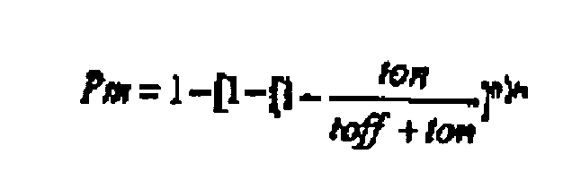
- P ntx 1 - ton ton + toff
- ton and toff represent the same information as defined above.
- n, ton, and toff have the same meanings as described above, and m represents the number of confidence signal transmissions made by a transmitting tag of interest (e.g., tag 5a1) .
- tags 5a1-5xx are transmitting distress signals at any one time, for a case wherein there are various numbers (0 to 1000) of tags 5a1-5xx randomly transmitting 12 bit packet, 1kbps information signals based upon a second average time interval of 15 second duration.
- Fig. 6 illustrates a graph representing probabilities that a particular one tag (e.g., tag 5a1) of 500 tags 5a1-5xx will successfully communicate 12 bit packet, 1kbps distress signals with the master transceiver 3 per each of 10 successive random transmissions occurring based upon a second average time interval of 15 second duration.
- tag 5a1 a particular one tag
- 1kbps distress signals with the master transceiver 3 per each of 10 successive random transmissions occurring based upon a second average time interval of 15 second duration.
- Fig. 7 illustrates a graph representing probabilities that no activated ones of various numbers (0 to 1000) of tags 5a1-5xx are transmitting distress signals at any one time, for a case wherein the tags 5a1-5xx are randomly transmitting 12 bit packet, 1 kbps information signals based upon a second average time interval of 1 second duration.
- Fig. 8 illustrates a graph representing probabilities that a particular one tag (e.g., tag 5a1) of 50 transmitting tags 5a1-5xx will successfully communicate 12 bit packet, 1 kbps distress signals with the master transceiver 3 per each of 10 successive transmissions, wherein each tag 5a1-5xx randomly transmits distress signals based upon a second average time interval of 1 second duration.
- tag 5a1 e.g., tag 5a1
- Fig. 9 illustrates a graph representing probabilities that no tags 5a1-5xx are transmitting information signals at any one time while the tags 5a1-5xx are operating in the confidence mode, wherein there are various numbers (0 to 10000) of tags 5a1-5xx randomly transmitting 17 bit packet, 1 kbps information signals of 17 millisecond pulse duration, based upon a first average time interval of 5 minute duration.
- Fig. 10 illustrates a graph representing probabilities that no tags 5a1-5xx are transmitting information signals at any one time, during the confidence mode of operation, for various numbers (0 to 10000) of tags 5a1-5xx that are randomly transmitting 17 bit packet, 120 bps information signals of 141 millisecond pulse duration, based upon a first average time interval of 5 minutes.
- Fig. 11 illustrates a graph representing probabilities that a particular one tag (e.g., tag 5a1) of 1000 tags 5a1-5xx will successfully communicate 17 bit packet, 1kbps, and 17 millisecond pulse duration information signals with the master transceiver 3 per each of 10 successive random transmissions occurring based upon a first average time interval of 5 minutes.
- tag 5a1 a particular one tag
- Fig. 11 illustrates a graph representing probabilities that a particular one tag (e.g., tag 5a1) of 1000 tags 5a1-5xx will successfully communicate 17 bit packet, 1kbps, and 17 millisecond pulse duration information signals with the master transceiver 3 per each of 10 successive random transmissions occurring based upon a first average time interval of 5 minutes.
- Fig. 12 illustrates a graph representing probabilities that a particular one tag (e.g., tag 5a1) of 1000 tags 5a1-5xx will successfully communicate 141 millisecond pulse duration information signals with the master transceiver 3 per each of 10 successive random transmissions occurring based upon a first average time interval of 5 minutes.
- tag 5a1 a particular one tag
- Fig. 12 illustrates a graph representing probabilities that a particular one tag (e.g., tag 5a1) of 1000 tags 5a1-5xx will successfully communicate 141 millisecond pulse duration information signals with the master transceiver 3 per each of 10 successive random transmissions occurring based upon a first average time interval of 5 minutes.
- this further embodiment is referred to as a "Transmit-Then-Receive" (TTR) protocol embodiment wherein individual tags 5a1-5xx transmit signals at intervals to the master transceiver 3 or a remote interrogator (e.g., remote interrogator 4a) in order to perform an inventorying of items (e.g., a paintings) associated with the tags, in the same manner as was described above.
- TTR Transmit-Then-Receive
- each transmission is followed by a predetermined waiting period, during which the tag operates in a receive mode, instead of a transmit mode, for a predetermined time interval.
- each of the master transceiver 3 and the remote transceivers 4a-4n comprises (in lieu of the DSSS TX block 44) the OOK TX block 46 which functions as described below.
- the OOK TX block 46 is a less complex system than the DSSS TX block 44.
- Fig. 4c illustrates an RX/TX tag constructed in accordance with a preferred embodiment of this invention.
- the RX/TX tag is similar to the transmit-only tag of the first embodiment of the invention in that it comprises a local oscillator 18, a modulator 15, an amplifier 16, a filter 19, a microprocessor controller 10, an "over-temperature” monitor sensor 14, a “bump” monitor sensor 12, an antenna 22, and an external user-interface 13. These elements function in a similar manner to the same elements of the transmit-only tag, although the controller 10 performs additional functions over that for the transmit-only tags.
- the RX/TX tag also comprises a larger memory (e.g., 1 to 100 kilobyte) 60 than the transmit-only tag (whose memory is not illustrated in Fig. 2) and circuitry, namely an OOK receiver circuit, enabling it to receive signals.
- the controller 10 controls the RX/TX tag to change its operating mode from the transmit mode to the receive mode for a time interval that is predetermined by, for example, information entered previously into controller 10 via the user-interface 13.
- the time interval is preferably a short time interval.
- an amplifier 64 has an input that is coupled to antenna 22 such that when the RX/TX tag is in a receive mode and a signal is received by the antenna 22, the signal is amplified to an appropriate level by amplifier 64.
- the amplifier 64 is tunable by an off-chip tuning block 66.
- a mixer 62 thereafter mixes the amplified signal with an output of local oscillator 18, whereafter the signal is amplified by amplifier 68 and thence filtered by a bandpass filter 70 (e.g., a 4.5MHz IF bandpass filter).
- a detector circuit 72 detects an output of the filter 70 and thereafter provides a signal to a logic block 74 which is, by example, a comparator.
- the comparator 74 determines whether a signal received from the detector 72 is of a sufficient magnitude (e.g., above a noise level). If so, the comparator 74 provides a signal to the controller 10, which thereafter changes the operating mode to the transmit mode (i.e., the controller 10 "turns off” or “cycles-off” the receiver circuitry and "turns on” or “cycles-on” the transmitter circuitry). Having a receive capability, the RX/TX tag can have its parameters (e.g., an ID number, a bill of lading, and first and/or second average time intervals) programmed from a remote location, as will be described below.
- parameters e.g., an ID number, a bill of lading, and first and/or second average time intervals
- the controller 10 controls the RX/TX tag to change its operating mode from the transmit mode to the receive mode as described above.
- the remote transceiver 4a receives the signal over antenna 48, which then provides the received signal to DSSS RX block 42, wherein appropriate receiving functions are performed to the signal (Fig. 3). After the signal passes through the DSSS RX block 42, the signal is provided to the processor 40.
- the processor 40 measures the frequency of the signal, which frequency was set originally at the transmitting RX/TX tag 5a1. This frequency measurement process occurs as a first step in the spread spectrum signal receive operation, and as such does not increase the complexity of the system. Following the frequency determination, the processor 40 controls the OOK TX block 46 to "cycle-on" so as to transmit a return data signal to the RX/TX tag 5a1 at a frequency that is offset from the measured frequency by a predetermined amount sufficient to optimize the performance of the RX/TX tag 5a1.
- the return data signal may carry information specifying, by example, a new first and/or second average time interval for the RX/TX tag 5a1, an identification number, or that the controller 10 of the RX/TX tag 5a1 shall cease the RX/TX tag 5a1 from making further transmissions.
- the processor 40 controls the OOK TX block 46 to turn off.
- This frequency adjustment scheme allows for improved system characteristics such as, by example, a relatively simple, inexpensive tag Local Oscillator (LO), the minimization of tag IF bandwidth requirements (thereby maximizing sensitivity and operational range), and an inexpensive OOK style receiver.
- LO Local Oscillator
- the signal traverses the receiving circuitry in the manner described above, ultimately being provided to controller 10. Thereafter, the controller 10 changes the operating mode from the receive mode to the transmit mode, and performs an error check to determine whether the received signal carries error-free data. If it is determined that the return signal does carry error-free data, the tag may indicate same by transmitting an acknowledgement signal back to the remote interrogator 4a.
- the RX/TX tag 5a1 may transmit a signal to the remote transceiver 4a requesting a re-transmission, whereafter the remote transceiver 4a re-transmits the signal until the TX/RX tag 5a1 controller 10 determines that the signal has been received without error. If the RX/TX controller 10 continually finds an error in the signals received from remote interrogator 4a, and the RX/TX tag 5a1 transmits a re-transmission request signal to the remote transceiver 4a a predetermined number of times, the remote transceiver 4a transmits a signal back to the master transceiver 3 indicating failure.
- the master transceiver 3 can function in the same manner as described above for the remote interrogator 4a.
- the application is described in the context in which the remote interrogator 4a sends a response signal to the RX/TX tag 5a1, in some applications it may not be necessary to send a response signal.
- data that is received without error need not be acknowledged back to the remote transceiver 4a.
- Fig. 4b illustrates a preferable approximate frequency (i.e., 2.414 GHz) of an RX tag local oscillator.
- Fig. 4b also shows possible receive band schemes for the RX/TX tag embodiment of the invention, including an ISM band for low power receive applications, and a higher-frequency licensed band for higher power applications.
- the tags because the tags transmit for short intervals, pause, and then change to a receive mode for a short interval, the tags operate in an energy-efficient manner.
Abstract
Claims (34)
- Un procédé permettant de comptabiliser des articles individuels parmi une pluralité d'articles, comprenant les étapes effectuant:la transmission de signaux d'information provenant d'étiquettes émettrices individuelles parmi une pluralité d'étiquettes émettrices (5a1-5xx) à un émetteur-récepteur maître (3), les transmissions de signaux d'information se produisant à des moments aléatoires à l'intérieur d'intervalles respectifs parmi une pluralité de premiers intervalles de temps prédéterminés successifs, les émetteurs individuels parmi la pluralité d'émetteurs étant fixés sur les articles individuels respectifs parmi la pluralité d'articles, les signaux d'information transmis à partir des étiquettes émettrices individuelles (5al-5xx) correspondant au moins aux articles respectifs sur lesquels les étiquettes émettrices (5a1-5xx) sont fixées; eten réponse à un signal d'entrée appliqué à au moins l'une des étiquettes émettrices (5a1-5xx), la transmission des signaux d'information provenant de la ou des étiquettes émettrices (5a1-5xx) à l'émetteur-récepteur maître (3) à des moments aléatoires à l'intérieur d'intervalles respectifs parmi une pluralité de seconds intervalles de temps prédéterminés successifs;caractérisé parà l'intérieur d'un poste de sécurité (2) couplé à l'émetteur-récepteur maître (3), en réponse à la réception de signaux individuels parmi les signaux d'information, la confirmation que les articles correspondant aux signaux d'information sont comptabilisés, etla détection dans le poste de sécurité (2) d'une variation de la vitesse à laquelle les signaux d'information sont reçus en provenance de la ou des étiquettes émettrices (5al-5xx) et ainsi la reconnaissance du fait qu'un événement prédéterminé s'est produit.
- Un procédé tel que présenté dans la revendication 1, dans lequel la durée de chacun desdits premiers intervalles de temps prédéterminés diffère de la durée de chacun desdits seconds intervalles de temps prédéterminés.
- Un procédé tel que présenté dans la revendication 1, dans lequel la durée de chacun des seconds intervalles de temps prédéterminés est plus courte que la durée de chacun des premiers intervalles de temps prédéterminés.
- Un procédé tel que présenté dans la revendication 1, dans lequel les étapes effectuant transmission des signaux d'information sont réalisées afin de transmettre les signaux d'information à au moins un émetteur-récepteur distant (4a-4n), dans lequel dans le cas où les signaux d'information sont transmis au ou aux émetteurs-récepteurs distants (4a-4n), le ou les émetteurs-récepteurs distants (4a-4n) relaient les signaux d'information à l'émetteur-récepteur maître (3).
- Un procédé tel que présenté dans la revendication 4, dans lequel le ou les émetteurs-récepteurs distants (4a-4n) reçoivent les signaux d'information selon, au moins en partie, une position du ou des émetteurs-récepteurs distants (4a-4n) par rapport à celle des étiquettes émettrices (5a1-5xx) qui transmettent les signaux d'information.
- Un procédé tel que présenté dans la revendication 4, dans lequel le fait que les signaux d'information soient transmis à l'émetteur-récepteur maître (3) ou à ou aux émetteurs-récepteurs distants (4a-4n) dépend, au moins en partie, des positions des étiquettes émettrices individuelles (5a1-5xx) qui transmettent les signaux d'information par rapport aux positions de l'émetteur-récepteur maître et du ou des émetteurs-récepteurs distants (4a-4n).
- Un procédé tel que présenté dans la revendication 1, dans lequel le signal d'entrée est généré en réponse à un utilisateur utilisant une interface utilisateur de la ou des étiquettes émettrices (5a1-5xx).
- Un procédé tel que présenté dans la revendication 1, dans lequel l'événement prédéterminé est au moins l'un des suivants: un mouvement, une tension de batterie atteignant un niveau prédéterminé, et une température prédéterminée qui est atteinte.
- Un procédé tel que présenté dans la revendication 1, comprenant en outre les étapes qui assurent:à l'intérieur de l'émetteur-récepteur maître (3), en réponse à la réception d'un signal individuel parmi les signaux d'information transmis à l'origine par une étiquette individuelle parmi les étiquettes émettrices (5a1-5xx), la mesure d'une intensité de signal du signal d'information reçu pour obtenir une intensité de signal mesurée du signal d'information reçu; etsur la base d'une différence entre l'intensité de signal mesurée du signal d'information reçu et l'intensité de signal de référence, la détermination d'au moins un déplacement et/ou un emplacement d'un article sur lequel l'étiquette émettrice individuelle (5a1-5xx) est fixée.
- Un procédé tel que présenté dans la revendication 1 ou 6, dans lequel les étapes effectuant transmission sont réalisées en utilisant une technique de modulation à spectre étalé à séquence directe (DSSS).
- Un procédé tel que présenté dans la revendication 1, dans lequel chaque étiquette individuelle parmi la pluralité d'étiquettes émettrices (5a1-5xx) transmet des signaux d'information indépendamment des autres étiquettes parmi la pluralité d'étiquettes émettrices (5a1-5xx), ce qui limite la probabilité que l'émetteur-récepteur maître (3) reçoive plus d'un signal d'information simultanément.
- Un procédé tel que présenté dans la revendication 1, dans lequel la probabilité qu'une étiquette individuelle parmi la pluralité d'étiquettes émettrices (5a1-5xx) transmette un signal d'information à un moment où aucune des autres étiquettes parmi la pluralité d'étiquettes émettrices (5a1-5xx) ne transmet des signaux d'information est représentée par Ptx, où:

- Un procédé tel que présenté dans la revendication 1, où la probabilité qu'une étiquette individuelle parmi la pluralité d'étiquettes émettrices (5a1-5xx) transmette un signal d'information durant une période de temps où aucune des autres étiquettes parmi la pluralité d'étiquettes émettrices (5a1-5xx) ne transmet des signaux d'information est représentée par Pm, où:
- Le procédé selon la revendication 1, dans lequel ladite ou lesdites étiquettes émettrices (5a1-5xx) possèdent un mode de transmission et un mode de réception, dans lequel lors du fonctionnement dans le mode de transmission, ladite ou lesdites étiquettes émettrices (5a1-5xx) possèdent une capacité de transmission des signaux et, lors du fonctionnement dans ledit mode de réception, ladite ou lesdites étiquettes émettrices possèdent une capacité de réception des signaux;
lorsque la ou les étiquettes émettrices (5a1-5xx) fonctionnent dans le mode de transmission, un premier signal est transmis à partir de la ou des étiquettes émettrices (5a1-5xx) audit émetteur-récepteur maître (3);
en réponse à l'exécution de l'étape de transmission, le mode de fonctionnement de la ou des étiquettes émettrices (5a1-5xx) passe du mode de transmission au mode de réception et la ou les étiquettes émettrices (5a1-5xx) fonctionnent dans le mode de réception pendant une période de temps prédéterminée; et
en réponse à l'expiration de la période de temps prédéterminée, le mode de fonctionnement de la ou des étiquettes émettrices (5a1-5xx) passe du mode de réception au mode de transmission. - Un procédé tel que présenté dans la revendication 14, dans lequel en réponse à l'émetteur-récepteur maître (3) recevant le premier signal, l'émetteur-récepteur maître (3) effectue les étapes effectuant:la détermination d'une fréquence du premier signal reçu pour obtenir une fréquence mesurée du premier signal; etdans lequel le second signal possède une fréquence qui est décalée d'un degré prédéterminé par rapport à la fréquence mesurée.
- Un procédé tel que présenté dans la revendication 15, dans lequel après la réception du second signal, la ou les étiquettes émettrices (5a1-5xx) contrôlent les erreurs du second signal et, après que le mode de fonctionnement de la ou des étiquettes émettrices (5a1-5xx) est passé au mode de transmission, la ou les étiquettes émettrices (5a1-5xx) transmettent un troisième signal au dispositif de réception (3) indiquant si une erreur a été détectée ou non durant la réception du second signal.
- Le procédé selon la revendication 4, comprenant en outre les étapes effectuant:à l'intérieur de l'émetteur-récepteur maître (3), le réglage d'une minuterie (10a) de manière à ce qu'elle fonctionne en réponse à la réception d'un premier signal parmi les signaux d'information provenant de la ou des étiquettes émettrices (5a1-5xx);le stockage à l'intérieur du ou des émetteurs-récepteurs distants (4a-4n) des informations qui indiquent un état d'alarme en réponse à l'un des événements suivants: (1) la minuterie atteignant une première valeur temporelle prédéterminée avant qu'un second signal parmi les signaux d'information ne soit reçu par le ou les émetteurs-récepteurs distants (4a-4n) en provenance de la ou des étiquettes émettrices (5a1-5xx) et (2) un second signal parmi les signaux d'information étant reçu par le ou les émetteurs-récepteurs distants avant que la minuterie (10a) n'atteigne une seconde valeur temporelle prédéterminée;la communication d'une commande d'interrogation par l'émetteur-récepteur maître (3) à ou aux émetteurs-récepteurs distants; eten réponse au ou aux émetteurs-récepteurs distants (4a-4n) recevant la commande d'interrogation, la communication des informations stockées par le ou les émetteurs-récepteurs distants (4a-4n) à l'émetteur-récepteur maître (3).
- Le procédé selon la revendication 4, comprenant en outre les étapes effectuant:la reconnaissance de l'apparition d'une condition affectant une étiquette individuelle parmi les étiquettes émettrices (5a1-5xx) en détectant que les signaux d'information reçus par le ou les émetteurs-récepteurs distants (4a-4n) en provenance de l'étiquette émettrice individuelle (5a1-5xx) ont des intensités différentes; etla notification à un émetteur-récepteur maître (3) du fait que la condition affectant l'étiquette émettrice individuelle (5a1-5xx) est apparue en réponse au ou aux émetteurs-récepteurs distants (4a-4n) recevant une commande d'interrogation en provenance de l'émetteur-récepteur maître (3).
- Un procédé tel que présenté dans la revendication 4, comprenant en outre l'étape effectuant:dans le ou les émetteurs-récepteurs (4a-4n), en réponse à la réception d'une paire de signaux comprenant au moins le premier et/ou le second signaux d'information transmis à l'origine à partir d'une étiquette individuelle parmi les étiquettes émettrices (5a1-5xx), la mesure de l'intensité de chaque paire comprenant ledit premier et/ou ledit second signaux d'information; etsur la base d'une relation entre les intensités mesurées de chaque paire comprenant ledit premier et/ou ledit second signaux d'information, la détermination d'un emplacement d'un article sur lequel l'étiquette émettrice (5a1-5xx) est fixée et/ou d'un déplacement de l'article par rapport à un emplacement de référence.
- Un procédé tel que présenté dans la revendication 18, dans lequel une autre étape est réalisée pour notifier à un utilisateur l'apparition de la condition.
- Un procédé tel que présenté dans la revendication 1, dans lequel le signal d'entrée est généré par un détecteur (12, 14) en réponse au détecteur détectant une condition prédéterminée et est ensuite appliqué à la ou aux étiquettes émettrices (5a1-5xx).
- Un système d'inventaire à intervalles de temps aléatoires permettant de comptabiliser des articles individuels parmi une pluralité d'articles, comprenant:une pluralité d'étiquettes émettrices (5a1-5xx), fixées sur les articles individuels respectifs de la pluralité d'articles, chacune des étiquettes émettrices (5a1-5xx) fonctionnant soit dans un premier mode de transmission soit dans un second mode de transmission, dans lequel lors du fonctionnement dans le premier mode de transmission, les étiquettes émettrices (5a1-5xx) transmettent les signaux d'information à des moments aléatoires à l'intérieur d'intervalles respectifs parmi une pluralité de premiers intervalles de temps prédéterminés successifs, et dans lequel lors du fonctionnement dans le second mode de transmission, les étiquettes émettrices (5a1-5xx) transmettent les signaux d'information à des moments aléatoires à l'intérieur d'intervalles respectifs parmi une pluralité de seconds intervalles de temps prédéterminés successifs, et dans lequel les étiquettes individuelles parmi lesdites étiquettes émettrices (5a1-5xx) fonctionnent dans ledit premier mode de transmission, lesdites étiquettes émettrices individuelles (5a1-5xx) réagissent à un signal d'entrée appliqué pour fonctionner dans ledit second mode de transmission;caractérisé parun poste de sécurité (2) distant de ladite étiquette émettrice (5a1-5xx), conçu pour, en réponse à la réception des signaux d'information, confirmer que les articles correspondant aux signaux d'information sont comptabilisés et pour détecter une variation de la vitesse à laquelle les signaux d'information sont reçus en provenance de la ou des étiquettes émettrices (5a1-5xx), ce qui permet de reconnaître qu'un événement prédéterminé s'est produit.
- Un système d'inventaire à intervalles de temps aléatoires tel que présenté dans la revendication 22, dans lequel les durées desdits premiers intervalles de temps prédéterminés diffèrent des durées desdits seconds intervalles de temps prédéterminés.
- Un système d'inventaire à intervalles de temps aléatoires tel que présenté dans la revendication 22, comprenant en outre:au moins un émetteur-récepteur maître (3) possédant une sortie, ledit ou lesdits émetteurs-récepteurs maîtres (3) permettant de recevoir des signaux d'information et permettant de fournir lesdits signaux d'information à ladite sortie;le poste de sécurité (2), possédant une entrée couplée à ladite sortie d'émetteur-récepteur maître (3), ledit poste de sécurité (2) permettant de confirmer qu'un article correspondant à un signal d'information reçu à ladite entrée est comptabilisé, ledit poste de sécurité (2) permettant également de détecter un changement de la vitesse à laquelle les signaux d'information sont reçus à ladite entrée pour reconnaître un état d'alarme; etdans lequel lesdites étiquettes émettrices (5a1-5xx) transmettent lesdits signaux d'information audit ou auxdits émetteurs-récepteurs maîtres (3) et audit ou auxdits émetteurs-récepteurs distants (4a-4n).
- Un système d'inventaire à intervalles de temps aléatoires tel que présenté dans la revendication 24, dans lequel dans le cas où lesdits signaux d'information sont transmis audit ou auxdits émetteurs-récepteurs distants (4a-4n), ledit ou lesdits émetteurs-récepteurs distants (4a-4n) reçoivent lesdits signaux d'information provenant d'au moins l'une des étiquettes parmi ladite pluralité d'étiquettes émettrices (5a1-5xx), et en réponse à ceux-ci, relaient lesdits signaux d'information reçus audit ou auxdits émetteurs-récepteurs maîtres (3).
- Un système d'inventaire à intervalles de temps aléatoires tel que présenté dans la revendication 25, dans lequel ledit ou lesdits émetteurs-récepteurs maîtres (3) et ledit ou lesdits émetteurs-récepteurs distants (4a-4n) comprennent au moins un émetteur utilisant la modulation à spectre étalé à séquence directe (DSSS) (44) et/ou un récepteur DSSS (42).
- Un système d'inventaire à intervalles de temps aléatoires tel que présenté dans la revendication 24, dans lequel ladite pluralité d'étiquettes émettrices (5a1-5xx) comprend au moins un émetteur utilisant la modulation à spectre étalé à séquence directe (DSSS) (44).
- Le système d'inventaire à intervalles de temps aléatoires selon la revendication 24, comprenant en outre:au moins un moyen de détection (12) couplé à ladite ou auxdites étiquettes émettrices pour détecter l'apparition d'un événement spécifique;dans lequel ladite étiquette émettrice (5a1-5xx) réagit audit moyen de détection (12) détectant un événement spécifique pour fonctionner dans le second mode parmi la pluralité de modes de transmission afin de transmettre les informations de l'événement détecté.
- Un système d'inventaire à intervalles de temps aléatoires tel que présenté dans la revendication 24, comprenant en outre au moins une ligne électrique, dans lequel ledit ou lesdits moyens de réception distants relaient lesdits signaux d'information reçus audit ou auxdits émetteurs-récepteurs maîtres (3) au moyen de ladite ou lesdites lignes électriques.
- Un système d'inventaire à intervalles de temps aléatoires selon la revendication 22, dans lequel chacune des étiquettes émettrices comprend:Une étiquette de réception/transmission (RX/TX) (5a1-5xx), comprenant:un contrôleur (10);une partie de récepteur; etune partie d'émetteur, ledit contrôleur (10) étant couplé à ladite partie de récepteur et à ladite partie d'émetteur, dans laquelle ledit contrôleur contrôle un mode de fonctionnement de ladite étiquette RX/TX, dans laquelle dans un premier mode de transmission de ladite étiquette RX/TX, ladite partie d'émetteur est activée et ladite partie de récepteur est désactivée sous le contrôle dudit contrôleur, dans laquelle dans le premier mode de transmission, ledit émetteur peut être contrôlé par ledit contrôleur (10) pour transmettre un signal provenant de l'étiquette RX/TX, dans laquelle après que le signal est transmis à partir de ladite étiquette RX/TX, ledit contrôleur (10) désactive ladite partie d'émetteur pendant une période de temps prédéterminée et active ladite partie de récepteur pendant la période de temps prédéterminée pour faire fonctionner l'étiquette RX/TX dans un second mode de réception pendant la période de temps prédéterminée, dans laquelle ledit contrôleur réagit à une expiration de ladite période de temps prédéterminée pour activer à nouveau ladite partie d'émetteur et désactiver à nouveau ladite partie de récepteur pour faire à nouveau fonctionner l'étiquette RX/TX dans le premier mode de transmission.
- Un système d'inventaire à intervalles de temps aléatoires selon la revendication 30, dans lequel ladite partie de récepteur comprend un émetteur avec une touche activation-désactivation (00K) et
dans lequel ledit récepteur de ladite étiquette RX/TX (5a1-5xx) est un récepteur 00K. - Un système d'inventaire à intervalles de temps aléatoires selon la revendication 22, dans lequel
la partie de récepteur reconnaît l'apparition d'une condition affectant les étiquettes individuelles en détectant que les signaux d'information reçus par le dispositif récepteur en provenance des étiquettes émettrices (5a1-5xx) ont des intensités différentes. - Un système d'inventaire à intervalles de temps aléatoires tel que présenté dans la revendication 32, comprenant en outre une interface utilisateur (13) et/ou un détecteur (12), dans lequel un signal d'information est généré à l'origine en réponse à un utilisateur utilisant l'interface utilisateur et/ou au détecteur (12) détectant une condition prédéterminée.
- Un système d'inventaire tel que présenté dans la revendication 22, comprenant en outre une interface utilisateur (13) et/ou un détecteur (12, 14), dans lequel ledit signal d'information est généré à l'origine en réponse à un utilisateur utilisant l'interface utilisateur et/ou au détecteur (12) détectant une condition prédéterminée.
Applications Claiming Priority (3)
| Application Number | Priority Date | Filing Date | Title |
|---|---|---|---|
| US667896 | 1996-06-20 | ||
| US08/667,896 US6058374A (en) | 1996-06-20 | 1996-06-20 | Inventorying method and system for monitoring items using tags |
| PCT/US1997/010657 WO1998000945A2 (fr) | 1996-06-20 | 1997-06-19 | Systeme d'inventaire a intervalles de temps aleatoires |
Publications (3)
| Publication Number | Publication Date |
|---|---|
| EP0974101A2 EP0974101A2 (fr) | 2000-01-26 |
| EP0974101A4 EP0974101A4 (fr) | 2000-06-28 |
| EP0974101B1 true EP0974101B1 (fr) | 2007-06-27 |
Family
ID=24680111
Family Applications (1)
| Application Number | Title | Priority Date | Filing Date |
|---|---|---|---|
| EP97932212A Expired - Lifetime EP0974101B1 (fr) | 1996-06-20 | 1997-06-19 | Systeme d'inventaire a intervalles de temps aleatoires |
Country Status (5)
| Country | Link |
|---|---|
| US (2) | US6058374A (fr) |
| EP (1) | EP0974101B1 (fr) |
| JP (1) | JP2002512739A (fr) |
| DE (1) | DE69737871T2 (fr) |
| WO (1) | WO1998000945A2 (fr) |
Families Citing this family (112)
| Publication number | Priority date | Publication date | Assignee | Title |
|---|---|---|---|---|
| US6393045B1 (en) * | 1997-09-26 | 2002-05-21 | Wherenet Corp. | Spread spectrum baseband modulation of magnetic fields for communications and proximity sensing |
| WO1999020845A1 (fr) * | 1997-10-22 | 1999-04-29 | The Yokohama Rubber Co., Ltd. | Defense et systeme de gestion pour cette derniere |
| US7844505B1 (en) | 1997-11-21 | 2010-11-30 | Symbol Technologies, Inc. | Automated real-time distributed tag reader network |
| US7035818B1 (en) * | 1997-11-21 | 2006-04-25 | Symbol Technologies, Inc. | System and method for electronic inventory |
| GB9804584D0 (en) * | 1998-03-04 | 1998-04-29 | Trolley Scan Pty Limited | Identification of objects by a reader |
| US6192222B1 (en) | 1998-09-03 | 2001-02-20 | Micron Technology, Inc. | Backscatter communication systems, interrogators, methods of communicating in a backscatter system, and backscatter communication methods |
| US6246882B1 (en) | 1998-12-22 | 2001-06-12 | Telefonaktiebolaget Lm Ericsson (Publ) | Wide area item tracking system |
| FR2790156A1 (fr) * | 1999-02-24 | 2000-08-25 | Groupe Ecoles Telecomm | Procede de transmission d'informations,notamment en parallele, entre une pluralite d'objets emetteurs et/ou recepteurs |
| US7592898B1 (en) * | 1999-03-09 | 2009-09-22 | Keystone Technology Solutions, Llc | Wireless communication systems, interrogators and methods of communicating within a wireless communication system |
| US6356764B1 (en) * | 1999-03-09 | 2002-03-12 | Micron Technology, Inc. | Wireless communication systems, interrogators and methods of communicating within a wireless communication system |
| US6603391B1 (en) * | 1999-03-09 | 2003-08-05 | Micron Technology, Inc. | Phase shifters, interrogators, methods of shifting a phase angle of a signal, and methods of operating an interrogator |
| AU1935201A (en) * | 1999-12-01 | 2001-06-12 | Ensure Technologies, Inc. | Method of linking authorized users to a plurality of devices |
| US7277866B1 (en) * | 2000-03-13 | 2007-10-02 | Zvi Or-Bach | System and method for consolidated shipping and receiving using reusable containers |
| US6958677B1 (en) * | 2000-03-31 | 2005-10-25 | Ge Medical Systems Information Technologies, Inc. | Object location monitoring system |
| DE60139872D1 (de) * | 2000-06-07 | 2009-10-22 | Tyco Electronics Logistics Ag | Verfahren und system zur überwachung und steuerung von arbeitskomponenten |
| US20020035524A1 (en) * | 2000-09-21 | 2002-03-21 | Martin Husslage | System and method for monitoring inventory amounts and locations |
| US20100330930A1 (en) * | 2000-12-22 | 2010-12-30 | Twitchell Robert W | Lprf device wake up using wireless tag |
| US8204439B2 (en) * | 2000-12-22 | 2012-06-19 | Google Inc. | Wireless reader tags (WRTs) with sensor components in asset monitoring and tracking systems |
| US8280345B2 (en) * | 2000-12-22 | 2012-10-02 | Google Inc. | LPRF device wake up using wireless tag |
| US7522568B2 (en) | 2000-12-22 | 2009-04-21 | Terahop Networks, Inc. | Propagating ad hoc wireless networks based on common designation and routine |
| US20080303897A1 (en) * | 2000-12-22 | 2008-12-11 | Terahop Networks, Inc. | Visually capturing and monitoring contents and events of cargo container |
| US7563991B2 (en) * | 2005-06-08 | 2009-07-21 | Terahop Networks, Inc. | All weather housing assembly for electronic components |
| US7554442B2 (en) * | 2005-06-17 | 2009-06-30 | Terahop Networks, Inc. | Event-driven mobile hazmat monitoring |
| JP4037269B2 (ja) * | 2001-02-12 | 2008-01-23 | シンボル テクノロジーズ インコーポレイテッド | 無線周波数識別アーキテクチャ |
| US6788199B2 (en) * | 2001-03-12 | 2004-09-07 | Eureka Technology Partners, Llc | Article locator system |
| US7232067B1 (en) * | 2001-05-15 | 2007-06-19 | Nicholas Sheppard Bromer | Registering multiple similar items with flickers |
| US20030004761A1 (en) * | 2001-06-28 | 2003-01-02 | Lampe Karen L. | System for reserving merchandise |
| US8339265B2 (en) | 2002-01-09 | 2012-12-25 | Sensormatic Electronics, Llc. | Method of assigning and deducing the location of articles detected by multiple RFID antennae |
| CN1639913B (zh) * | 2002-01-09 | 2010-05-26 | Vue科技公司 | 使用多个射频天线的智能站、包括智能站的库存控制系统及方法 |
| US6972682B2 (en) | 2002-01-18 | 2005-12-06 | Georgia Tech Research Corporation | Monitoring and tracking of assets by utilizing wireless communications |
| US6783367B1 (en) * | 2002-02-19 | 2004-08-31 | Cisco Technology, Inc. | Method and system for providing a global product services electronic laboratory |
| US9471818B2 (en) * | 2002-03-13 | 2016-10-18 | Nxp B.V. | Communication station for communication with transponders and further communication stations with the aid of different protocols |
| US7009496B2 (en) * | 2002-04-01 | 2006-03-07 | Symbol Technologies, Inc. | Method and system for optimizing an interrogation of a tag population |
| EP2192421A1 (fr) * | 2002-07-29 | 2010-06-02 | Nippon Telegraph and Telephone Corporation | Système de localisation et procédé pour déterminer la position d'objets |
| US6972677B2 (en) | 2002-08-27 | 2005-12-06 | Coulthard John J | Monitoring system |
| US6975206B2 (en) * | 2002-08-30 | 2005-12-13 | Intellectual Property, Llc | Method for communication between central terminal and multiple transponders |
| US7002472B2 (en) * | 2002-09-04 | 2006-02-21 | Northrop Grumman Corporation | Smart and secure container |
| US6927692B1 (en) | 2002-09-05 | 2005-08-09 | American Greetings Corporation | RF inventory system |
| US20040049428A1 (en) * | 2002-09-05 | 2004-03-11 | Soehnlen John Pius | Wireless environmental sensing in packaging applications |
| US7444401B1 (en) | 2002-11-18 | 2008-10-28 | Arkion Systems Llc | Method and apparatus for inexpensively monitoring and controlling remotely distributed appliances |
| US7283048B2 (en) * | 2003-02-03 | 2007-10-16 | Ingrid, Inc. | Multi-level meshed security network |
| US7057512B2 (en) * | 2003-02-03 | 2006-06-06 | Ingrid, Inc. | RFID reader for a security system |
| US7532114B2 (en) * | 2003-02-03 | 2009-05-12 | Ingrid, Inc. | Fixed part-portable part communications network for a security network |
| US7091827B2 (en) | 2003-02-03 | 2006-08-15 | Ingrid, Inc. | Communications control in a security system |
| US20060132302A1 (en) * | 2003-02-03 | 2006-06-22 | Stilp Louis A | Power management of transponders and sensors in an RFID security network |
| US7511614B2 (en) * | 2003-02-03 | 2009-03-31 | Ingrid, Inc. | Portable telephone in a security network |
| US7042353B2 (en) | 2003-02-03 | 2006-05-09 | Ingrid, Inc. | Cordless telephone system |
| US7119658B2 (en) | 2003-02-03 | 2006-10-10 | Ingrid, Inc. | Device enrollment in a security system |
| US7495544B2 (en) * | 2003-02-03 | 2009-02-24 | Ingrid, Inc. | Component diversity in a RFID security network |
| US7079034B2 (en) * | 2003-02-03 | 2006-07-18 | Ingrid, Inc. | RFID transponder for a security system |
| WO2004070697A1 (fr) * | 2003-02-03 | 2004-08-19 | Sharp Kabushiki Kaisha | Afficheur a cristaux liquides |
| US7079020B2 (en) * | 2003-02-03 | 2006-07-18 | Ingrid, Inc. | Multi-controller security network |
| US20090267747A1 (en) * | 2003-03-31 | 2009-10-29 | Rivest Ronald L | Security and Data Collision Systems and Related Techniques for Use With Radio Frequency Identification Systems |
| SG118198A1 (en) * | 2003-07-31 | 2006-01-27 | Kenetics Innovations Pte Ltd | Use of RFID tags and readers to automate real timealert signals in a security system |
| US7394372B2 (en) * | 2003-12-30 | 2008-07-01 | G2 Microsystems Pty. Ltd. | Method and apparatus for aggregating and communicating tracking information |
| WO2006018231A1 (fr) * | 2004-08-16 | 2006-02-23 | Giesecke & Devrient Gmbh | Chargement sans contact commande d'un accumulateur d'une carte a puce |
| WO2006093992A2 (fr) * | 2005-03-01 | 2006-09-08 | I.D. Systems, Inc. | Portail mobile pour applications d'identification par radiofrequence (rfid) |
| US20060220874A1 (en) * | 2005-03-03 | 2006-10-05 | Campero Richard J | Apparatus for and method of using an intelligent network and RFID signal router |
| CA2603118A1 (fr) * | 2005-03-29 | 2006-10-05 | Symbol Technologies, Inc. | Articles intelligents d'identification de radiofrequences (rfid) |
| WO2006107282A1 (fr) | 2005-04-07 | 2006-10-12 | National University Of Singapore | Systeme et procede de recherche d'objets physiques |
| US7828342B2 (en) * | 2005-07-29 | 2010-11-09 | Terahop Networks, Inc. | Reusable locking body, of bolt-type seal lock, having open-ended passageway and U-shaped bolt |
| US9041513B1 (en) * | 2005-10-03 | 2015-05-26 | National Semiconductor Corporation | System and method for communicating with sensors/loggers in integrated radio frequency identification (RFID) tags |
| US20070126556A1 (en) * | 2005-12-07 | 2007-06-07 | Kovio, Inc. | Printed radio frequency identification (RFID) tag using tags-talk-first (TTF) protocol |
| US8316156B2 (en) * | 2006-02-17 | 2012-11-20 | Intel-Ne, Inc. | Method and apparatus for interfacing device drivers to single multi-function adapter |
| US8690117B2 (en) | 2006-05-04 | 2014-04-08 | Capstone Metering Llc | Water meter |
| WO2007131169A2 (fr) * | 2006-05-04 | 2007-11-15 | Capstone Mobile Technologies, Llc | système et procédé pour surveiller et commander à distance un compteur d'eau |
| US20080061940A1 (en) * | 2006-08-03 | 2008-03-13 | Kimberly-Clark Worldwide, Inc. | Smart antenna system for reading data tags |
| US8994533B2 (en) * | 2006-11-30 | 2015-03-31 | Patent Navigation, Inc. | Conditional RFID |
| CN101755275A (zh) * | 2007-05-25 | 2010-06-23 | 胡斯曼公司 | 供应链管理系统 |
| US9202190B2 (en) * | 2007-05-29 | 2015-12-01 | Sap Se | Method for tracking and controlling grainy and fluid bulk goods in stream-oriented transportation process using RFID devices |
| US8319607B2 (en) * | 2007-08-29 | 2012-11-27 | Seeonic, Inc. | Inventory monitoring system |
| US7502619B1 (en) * | 2008-01-22 | 2009-03-10 | Katz Daniel A | Location determination of low power wireless devices over a wide area |
| ES2730077T3 (es) | 2008-10-27 | 2019-11-08 | Mueller Int Llc | Sistema y método de monitoreo de infraestructura |
| US8217785B2 (en) * | 2008-10-28 | 2012-07-10 | Research In Motion Limited | Mobile tag tracking system |
| US8705523B2 (en) | 2009-02-05 | 2014-04-22 | Google Inc. | Conjoined class-based networking |
| AU2010249499B2 (en) * | 2009-05-22 | 2015-01-29 | Mueller International Llc | Infrastructure monitoring devices, systems, and methods |
| EP2435949A4 (fr) * | 2009-05-29 | 2014-04-30 | Ericsson Telefon Ab L M | Appareil, procédé et produit programme d'ordinateur pour détecter des drapeaux de risque |
| US8074890B2 (en) * | 2009-09-04 | 2011-12-13 | Consortium P, Inc. | Wearable data transceiver with coupled antenna |
| GB201013128D0 (en) * | 2009-09-24 | 2010-09-22 | Barloworld Handling Ltd | Maintence control system |
| EP2582886B1 (fr) | 2010-06-16 | 2019-11-27 | Mueller International, LLC | Dispositifs, systèmes et procédés de surveillance d'infrastructure |
| US8787961B2 (en) * | 2010-08-09 | 2014-07-22 | Gene Ryan Skalicky | Safety and tracking system and related devices |
| US8549367B1 (en) * | 2010-12-29 | 2013-10-01 | Cadence Design Systems, Inc. | Method and system for accelerating memory randomization |
| AU2012202173B2 (en) | 2011-04-18 | 2013-09-05 | Castle Bookkeeping Wizard Pty Ltd | System and method for processing a transaction document including one or more financial transaction entries |
| US8833390B2 (en) | 2011-05-31 | 2014-09-16 | Mueller International, Llc | Valve meter assembly and method |
| WO2013003813A1 (fr) | 2011-06-30 | 2013-01-03 | Lutron Electronics Co., Inc. | Dispositif et procédé permettant de transmettre de façon optique des informations numériques à partir d'un smart phone vers un dispositif de commande de charge |
| WO2013003804A2 (fr) | 2011-06-30 | 2013-01-03 | Lutron Electronics Co., Inc. | Procédé de programmation de dispositif de régulation de charge à l'aide de téléphone intelligent |
| WO2013012547A1 (fr) | 2011-06-30 | 2013-01-24 | Lutron Electronics Co., Inc. | Dispositif de commande de charge ayant une connectivité internet, et procédé de programmation de celui-ci à l'aide d'un téléphone intelligent |
| JP5912330B2 (ja) * | 2011-08-05 | 2016-04-27 | 任天堂株式会社 | システム、発信機および管理方法 |
| US9368025B2 (en) | 2011-08-29 | 2016-06-14 | Lutron Electronics Co., Inc. | Two-part load control system mountable to a single electrical wallbox |
| US8660134B2 (en) | 2011-10-27 | 2014-02-25 | Mueller International, Llc | Systems and methods for time-based hailing of radio frequency devices |
| US8855569B2 (en) | 2011-10-27 | 2014-10-07 | Mueller International, Llc | Systems and methods for dynamic squelching in radio frequency devices |
| US10019047B2 (en) | 2012-12-21 | 2018-07-10 | Lutron Electronics Co., Inc. | Operational coordination of load control devices for control of electrical loads |
| US10244086B2 (en) | 2012-12-21 | 2019-03-26 | Lutron Electronics Co., Inc. | Multiple network access load control devices |
| US9413171B2 (en) | 2012-12-21 | 2016-08-09 | Lutron Electronics Co., Inc. | Network access coordination of load control devices |
| US10135629B2 (en) | 2013-03-15 | 2018-11-20 | Lutron Electronics Co., Inc. | Load control device user interface and database management using near field communication (NFC) |
| CA3128758A1 (fr) | 2013-03-15 | 2014-09-25 | Mueller International, Llc | Systemes pour mesurer des proprietes d'eau dans un systeme de distribution d'eau |
| US11080644B2 (en) * | 2013-05-06 | 2021-08-03 | Fedex Corporate Services, Inc. | Methods, systems, and devices for detecting and resolving risks associated with shipped objects |
| US9590453B2 (en) | 2013-06-11 | 2017-03-07 | Lutron Electronics Co., Inc. | Configuring communications for a load control system |
| US9112790B2 (en) | 2013-06-25 | 2015-08-18 | Google Inc. | Fabric network |
| US10121028B2 (en) | 2013-06-26 | 2018-11-06 | Vypin, LLC | Asset tag apparatus and related methods |
| US9904885B2 (en) * | 2014-04-06 | 2018-02-27 | Vypin, LLC | Wireless medication compliance sensing device, system, and related methods |
| US10572700B2 (en) | 2013-06-26 | 2020-02-25 | Vypin, LLC | Wireless asset location tracking system and related techniques |
| US9633551B2 (en) * | 2013-11-20 | 2017-04-25 | Aeroscout Ltd. | Enhanced wireless location system and method |
| US9494249B2 (en) | 2014-05-09 | 2016-11-15 | Mueller International, Llc | Mechanical stop for actuator and orifice |
| US9460323B2 (en) | 2014-06-23 | 2016-10-04 | Sony Corporation | Tag powersave |
| US9565620B2 (en) | 2014-09-02 | 2017-02-07 | Mueller International, Llc | Dynamic routing in a mesh network |
| US10430758B2 (en) * | 2015-01-19 | 2019-10-01 | Aesynt Incorporated | Cycle count based inventory management |
| AU2016270807A1 (en) * | 2015-06-01 | 2017-12-14 | The Board Of Trustees Of The University Of Illinois | Miniaturized electronic systems with wireless power and near-field communication capabilities |
| US11029198B2 (en) | 2015-06-01 | 2021-06-08 | The Board Of Trustees Of The University Of Illinois | Alternative approach for UV sensing |
| US11041839B2 (en) | 2015-06-05 | 2021-06-22 | Mueller International, Llc | Distribution system monitoring |
| WO2021100806A1 (fr) | 2019-11-20 | 2021-05-27 | 京セラ株式会社 | Système d'accumulation de données et procédé d'accumulation de données |
| US11725366B2 (en) | 2020-07-16 | 2023-08-15 | Mueller International, Llc | Remote-operated flushing system |
Family Cites Families (62)
| Publication number | Priority date | Publication date | Assignee | Title |
|---|---|---|---|---|
| US3163856A (en) * | 1961-11-14 | 1964-12-29 | Frederick G Kirby | Alarm device for indicating lack of motion |
| AU498573B2 (en) * | 1974-06-18 | 1979-03-15 | Aboyne Pty. Ltd. | Information transmission system |
| US4044351A (en) * | 1974-06-24 | 1977-08-23 | Walter Kidde & Company, Inc. | System monitor with innate line security ability |
| GB2043314A (en) * | 1979-02-27 | 1980-10-01 | Essex County Council | Line signaling apparatus |
| US4367458A (en) * | 1980-08-29 | 1983-01-04 | Ultrak Inc. | Supervised wireless security system |
| US4471345A (en) * | 1982-03-05 | 1984-09-11 | Sensormatic Electronics Corporation | Randomized tag to portal communication system |
| US4636950A (en) * | 1982-09-30 | 1987-01-13 | Caswell Robert L | Inventory management system using transponders associated with specific products |
| US4656463A (en) * | 1983-04-21 | 1987-04-07 | Intelli-Tech Corporation | LIMIS systems, devices and methods |
| US4862160A (en) * | 1983-12-29 | 1989-08-29 | Revlon, Inc. | Item identification tag for rapid inventory data acquisition system |
| US4593273A (en) * | 1984-03-16 | 1986-06-03 | Narcisse Bernadine O | Out-of-range personnel monitor and alarm |
| US4675656A (en) * | 1984-03-16 | 1987-06-23 | Narcisse Bernadine O | Out-of-range personnel monitor and alarm |
| US4747120A (en) * | 1985-08-13 | 1988-05-24 | Digital Products Corporation | Automatic personnel monitoring system |
| US4611198A (en) * | 1985-09-19 | 1986-09-09 | Levinson Samuel H | Security and communication system |
| US4734680A (en) * | 1986-02-06 | 1988-03-29 | Emhart Industries, Inc. | Detection system with randomized transmissions |
| US4885571A (en) * | 1986-04-15 | 1989-12-05 | B. I. Incorperated | Tag for use with personnel monitoring system |
| US4952913A (en) * | 1986-04-15 | 1990-08-28 | B. I. Incorporated | Tag for use with personnel monitoring system |
| US4710751A (en) * | 1986-04-24 | 1987-12-01 | Environmental Protection Systems | Ground fault monitor circuit |
| US4857893A (en) * | 1986-07-18 | 1989-08-15 | Bi Inc. | Single chip transponder device |
| EP0270274A3 (fr) * | 1986-12-05 | 1990-01-24 | Meridian Micro-Systems Limited | Répondeur et interrogateur |
| US4814751A (en) * | 1987-02-27 | 1989-03-21 | Wildlife Materials, Inc. | Patient tracking system |
| US5153583A (en) * | 1987-11-18 | 1992-10-06 | Uniscan Ltd. | Transponder |
| US4853692A (en) * | 1987-12-07 | 1989-08-01 | Wolk Barry M | Infant security system |
| US5113349A (en) * | 1988-03-26 | 1992-05-12 | Fuji Electric Co. Ltd. | Method and system for storing/removing and distributing articles of manufacture |
| ATE109292T1 (de) * | 1988-05-27 | 1994-08-15 | Digital Products Corp | Belegschafts-sicherheitsüberwachungsvorrichtung |
| US5204670A (en) * | 1988-08-29 | 1993-04-20 | B. I. Incorporated | Adaptable electric monitoring and identification system |
| US4952928A (en) * | 1988-08-29 | 1990-08-28 | B. I. Incorporated | Adaptable electronic monitoring and identification system |
| US4918432A (en) * | 1988-09-27 | 1990-04-17 | B. I. Incorporated | House arrest monitoring system |
| JPH02269989A (ja) * | 1988-10-14 | 1990-11-05 | Total Alert Corp | 個人位置伝送器 |
| US4899135A (en) * | 1988-12-05 | 1990-02-06 | Mehdi Ghahariiran | Child monitoring device |
| US5029183A (en) * | 1989-06-29 | 1991-07-02 | Symbol Technologies, Inc. | Packet data communication network |
| US5021794A (en) * | 1989-08-15 | 1991-06-04 | Lawrence Robert A | Personal emergency locator system |
| US5422626A (en) * | 1989-08-15 | 1995-06-06 | Fish; David | Electrical monitoring system |
| US4998095A (en) * | 1989-10-19 | 1991-03-05 | Specific Cruise Systems, Inc. | Emergency transmitter system |
| US4975681A (en) * | 1989-12-07 | 1990-12-04 | Sensormatic Electronics Corporation | Interfering signal rejection circuitry and electronic article surveillance system and method employing same |
| US5028918A (en) * | 1989-12-18 | 1991-07-02 | Dairy Equipment Company | Identification transponder circuit |
| US5047750A (en) * | 1990-03-09 | 1991-09-10 | Hector Larry F | Non-intrusive infant security system |
| US5079541A (en) * | 1990-06-04 | 1992-01-07 | Moody Thomas O | System and method for detecting movement of an infant from a secure area |
| US5075670A (en) * | 1990-08-01 | 1991-12-24 | Digital Products Corporation | Personnel monitoring tag with tamper detection and secure reset |
| US5182543A (en) * | 1990-09-12 | 1993-01-26 | Board Of Trustees Operating Michigan State University | Miniaturized data communication and identification system |
| US5115223A (en) * | 1990-09-20 | 1992-05-19 | Moody Thomas O | Personnel location monitoring system and method |
| JP3143123B2 (ja) * | 1990-11-06 | 2001-03-07 | マイクロン・テクノロジー・インコーポレイテッド | デュアルモード電子識別システム |
| US5231273A (en) * | 1991-04-09 | 1993-07-27 | Comtec Industries | Inventory management system |
| US5189395A (en) * | 1991-05-10 | 1993-02-23 | Bi, Inc. | Electronic house arrest system having officer safety reporting feature |
| US5266926A (en) * | 1991-05-31 | 1993-11-30 | Avid Marketing, Inc. | Signal transmission and tag power consumption measurement circuit for an inductive reader |
| US5115224A (en) * | 1991-07-05 | 1992-05-19 | Detection Systems, Inc. | Personal security system network |
| US5218344A (en) * | 1991-07-31 | 1993-06-08 | Ricketts James G | Method and system for monitoring personnel |
| US5365516A (en) * | 1991-08-16 | 1994-11-15 | Pinpoint Communications, Inc. | Communication system and method for determining the location of a transponder unit |
| US5363425A (en) * | 1992-06-29 | 1994-11-08 | Northern Telecom Limited | Method and apparatus for providing a personal locator, access control and asset tracking service using an in-building telephone network |
| IL102737A (en) * | 1992-08-05 | 1995-11-27 | Technion Res & Dev Foundation | Return of modulated digital frequency signals to their original state |
| US5289163A (en) * | 1992-09-16 | 1994-02-22 | Perez Carla D | Child position monitoring and locating device |
| US5426425A (en) * | 1992-10-07 | 1995-06-20 | Wescom, Inc. | Intelligent locator system with multiple bits represented in each pulse |
| US5287384A (en) * | 1992-10-15 | 1994-02-15 | Lxe Inc. | Frequency hopping spread spectrum data communications system |
| US5289499A (en) * | 1992-12-29 | 1994-02-22 | At&T Bell Laboratories | Diversity for direct-sequence spread spectrum systems |
| US5347263A (en) * | 1993-02-05 | 1994-09-13 | Gnuco Technology Corporation | Electronic identifier apparatus and method utilizing a single chip microcontroller and an antenna coil |
| US5491468A (en) * | 1993-06-24 | 1996-02-13 | Westinghouse Electric Corporation | Identification system and method with passive tag |
| US5448221A (en) * | 1993-07-29 | 1995-09-05 | Weller; Robert N. | Dual alarm apparatus for monitoring of persons under house arrest |
| US5576689A (en) * | 1993-08-27 | 1996-11-19 | Queen; Andrew | Self testing personal response system with programmable timer values |
| US5416468A (en) * | 1993-10-29 | 1995-05-16 | Motorola, Inc. | Two-tiered system and method for remote monitoring |
| US5434775A (en) * | 1993-11-04 | 1995-07-18 | The General Hospital Corporation | Managing an inventory of devices |
| US5440295A (en) * | 1994-05-02 | 1995-08-08 | Ciecwisz; Richard A. | Apparatus and method for preventing unauthorized removal of a newborn infant from a predetermined area |
| US5589821A (en) * | 1994-12-13 | 1996-12-31 | Secure Technologies, Inc. | Distance determination and alarm system |
| US5617074A (en) * | 1995-11-02 | 1997-04-01 | White; Marvin D. | Child finder |
-
1996
- 1996-06-20 US US08/667,896 patent/US6058374A/en not_active Expired - Lifetime
-
1997
- 1997-06-19 JP JP50419098A patent/JP2002512739A/ja not_active Ceased
- 1997-06-19 DE DE69737871T patent/DE69737871T2/de not_active Expired - Lifetime
- 1997-06-19 WO PCT/US1997/010657 patent/WO1998000945A2/fr active IP Right Grant
- 1997-06-19 EP EP97932212A patent/EP0974101B1/fr not_active Expired - Lifetime
-
1999
- 1999-05-18 US US09/314,430 patent/US20020087436A1/en not_active Abandoned
Also Published As
| Publication number | Publication date |
|---|---|
| DE69737871D1 (de) | 2007-08-09 |
| US6058374A (en) | 2000-05-02 |
| WO1998000945A2 (fr) | 1998-01-08 |
| WO1998000945A3 (fr) | 1998-02-12 |
| US20020087436A1 (en) | 2002-07-04 |
| EP0974101A4 (fr) | 2000-06-28 |
| DE69737871T2 (de) | 2008-02-28 |
| EP0974101A2 (fr) | 2000-01-26 |
| JP2002512739A (ja) | 2002-04-23 |
Similar Documents
| Publication | Publication Date | Title |
|---|---|---|
| EP0974101B1 (fr) | Systeme d'inventaire a intervalles de temps aleatoires | |
| EP0904582B1 (fr) | Etiquette de surveillance personnelle | |
| US5887176A (en) | Method and system for remote monitoring and tracking of inventory | |
| US4462022A (en) | Security system with radio frequency coupled remote sensors | |
| US6265963B1 (en) | Methods of processing wireless communication, methods of processing radio frequency communication, and related systems | |
| US7408456B2 (en) | Wireless communication system | |
| US6499656B1 (en) | Identification of objects by a reader | |
| US7991354B2 (en) | Method of communication and base station | |
| US4794268A (en) | Automotive keyless entry system incorporating portable radio self-identifying code signal transmitter | |
| US6566997B1 (en) | Interference control method for RFID systems | |
| EP0694860B1 (fr) | Appareil et méthode pour identifier une multiplicité de transpondeurs | |
| US7156312B2 (en) | RFID tag having multiple transceivers | |
| EP2202704B1 (fr) | Dispositif de communication de données de fréquence radio | |
| US7944369B2 (en) | Wireless sensing device, system and method | |
| US6420961B1 (en) | Wireless communication systems, interfacing devices, communication methods, methods of interfacing with an interrogator, and methods of operating an interrogator | |
| US20060220785A1 (en) | Generic radio transmission network for door applications | |
| WO1998000945B1 (fr) | Systeme d'inventaire a intervalles de temps aleatoires | |
| KR20010034624A (ko) | 복수의 원격 장치와 제어 장치간의 통신 방법 | |
| WO1998016849A1 (fr) | Systeme de poursuite d'articles | |
| US20020171534A1 (en) | Identification system | |
| WO2001069557A2 (fr) | Systeme et procede pour simplifier la vie d'une personne |
Legal Events
| Date | Code | Title | Description |
|---|---|---|---|
| PUAI | Public reference made under article 153(3) epc to a published international application that has entered the european phase |
Free format text: ORIGINAL CODE: 0009012 |
|
| 17P | Request for examination filed |
Effective date: 19990111 |
|
| AK | Designated contracting states |
Kind code of ref document: A2 Designated state(s): DE FR GB SE |
|
| A4 | Supplementary search report drawn up and despatched |
Effective date: 20000517 |
|
| AK | Designated contracting states |
Kind code of ref document: A4 Designated state(s): DE FR GB SE |
|
| RIC1 | Information provided on ipc code assigned before grant |
Free format text: 7G 06F 15/00 A, 7G 06K 17/00 B |
|
| GRAP | Despatch of communication of intention to grant a patent |
Free format text: ORIGINAL CODE: EPIDOSNIGR1 |
|
| GRAS | Grant fee paid |
Free format text: ORIGINAL CODE: EPIDOSNIGR3 |
|
| GRAA | (expected) grant |
Free format text: ORIGINAL CODE: 0009210 |
|
| AK | Designated contracting states |
Kind code of ref document: B1 Designated state(s): DE FR GB SE |
|
| REG | Reference to a national code |
Ref country code: GB Ref legal event code: FG4D |
|
| REF | Corresponds to: |
Ref document number: 69737871 Country of ref document: DE Date of ref document: 20070809 Kind code of ref document: P |
|
| REG | Reference to a national code |
Ref country code: SE Ref legal event code: TRGR |
|
| ET | Fr: translation filed | ||
| PLBE | No opposition filed within time limit |
Free format text: ORIGINAL CODE: 0009261 |
|
| STAA | Information on the status of an ep patent application or granted ep patent |
Free format text: STATUS: NO OPPOSITION FILED WITHIN TIME LIMIT |
|
| 26N | No opposition filed |
Effective date: 20080328 |
|
| REG | Reference to a national code |
Ref country code: GB Ref legal event code: 732E Free format text: REGISTERED BETWEEN 20110428 AND 20110504 |
|
| REG | Reference to a national code |
Ref country code: FR Ref legal event code: TP Owner name: NORTHROP GRUMMAN SYSTEMS CORPORATION, US Effective date: 20120314 |
|
| REG | Reference to a national code |
Ref country code: DE Ref legal event code: R082 Ref document number: 69737871 Country of ref document: DE Representative=s name: BEETZ & PARTNER PATENT- UND RECHTSANWAELTE, DE |
|
| REG | Reference to a national code |
Ref country code: DE Ref legal event code: R082 Ref document number: 69737871 Country of ref document: DE Representative=s name: BEETZ & PARTNER MBB PATENT- UND RECHTSANWAELTE, DE Effective date: 20130205 Ref country code: DE Ref legal event code: R082 Ref document number: 69737871 Country of ref document: DE Representative=s name: BEETZ & PARTNER MBB, DE Effective date: 20130205 Ref country code: DE Ref legal event code: R082 Ref document number: 69737871 Country of ref document: DE Representative=s name: BEETZ & PARTNER PATENT- UND RECHTSANWAELTE, DE Effective date: 20130205 Ref country code: DE Ref legal event code: R081 Ref document number: 69737871 Country of ref document: DE Owner name: NORTHROP GRUMMAN SYSTEMS CORPORATION (N.D.GES., US Free format text: FORMER OWNER: NORTHROP GRUMMAN CORP., LOS ANGELES, CALIF., US Effective date: 20130205 Ref country code: DE Ref legal event code: R081 Ref document number: 69737871 Country of ref document: DE Owner name: NORTHROP GRUMMAN SYSTEMS CORPORATION (N.D.GES., US Free format text: FORMER OWNER: NORTHROP GRUMMAN CORP., LOS ANGELES, US Effective date: 20130205 |
|
| REG | Reference to a national code |
Ref country code: FR Ref legal event code: PLFP Year of fee payment: 19 |
|
| PGFP | Annual fee paid to national office [announced via postgrant information from national office to epo] |
Ref country code: DE Payment date: 20150619 Year of fee payment: 19 Ref country code: SE Payment date: 20150618 Year of fee payment: 19 Ref country code: GB Payment date: 20150618 Year of fee payment: 19 |
|
| PGFP | Annual fee paid to national office [announced via postgrant information from national office to epo] |
Ref country code: FR Payment date: 20150619 Year of fee payment: 19 |
|
| REG | Reference to a national code |
Ref country code: DE Ref legal event code: R119 Ref document number: 69737871 Country of ref document: DE |
|
| REG | Reference to a national code |
Ref country code: SE Ref legal event code: EUG |
|
| PG25 | Lapsed in a contracting state [announced via postgrant information from national office to epo] |
Ref country code: SE Free format text: LAPSE BECAUSE OF NON-PAYMENT OF DUE FEES Effective date: 20160620 |
|
| GBPC | Gb: european patent ceased through non-payment of renewal fee |
Effective date: 20160619 |
|
| REG | Reference to a national code |
Ref country code: FR Ref legal event code: ST Effective date: 20170228 |
|
| PG25 | Lapsed in a contracting state [announced via postgrant information from national office to epo] |
Ref country code: DE Free format text: LAPSE BECAUSE OF NON-PAYMENT OF DUE FEES Effective date: 20170103 Ref country code: FR Free format text: LAPSE BECAUSE OF NON-PAYMENT OF DUE FEES Effective date: 20160630 |
|
| PG25 | Lapsed in a contracting state [announced via postgrant information from national office to epo] |
Ref country code: GB Free format text: LAPSE BECAUSE OF NON-PAYMENT OF DUE FEES Effective date: 20160619 |