EP0979991A1 - Measuring system for a pressure sensing device and method of manufacturing a measuring system for a pressure sensing device - Google Patents
Measuring system for a pressure sensing device and method of manufacturing a measuring system for a pressure sensing device Download PDFInfo
- Publication number
- EP0979991A1 EP0979991A1 EP98113938A EP98113938A EP0979991A1 EP 0979991 A1 EP0979991 A1 EP 0979991A1 EP 98113938 A EP98113938 A EP 98113938A EP 98113938 A EP98113938 A EP 98113938A EP 0979991 A1 EP0979991 A1 EP 0979991A1
- Authority
- EP
- European Patent Office
- Prior art keywords
- spring
- end piece
- measuring system
- spring end
- board
- Prior art date
- Legal status (The legal status is an assumption and is not a legal conclusion. Google has not performed a legal analysis and makes no representation as to the accuracy of the status listed.)
- Granted
Links
- 238000004519 manufacturing process Methods 0.000 title claims abstract description 31
- 238000000034 method Methods 0.000 claims abstract description 20
- 230000007246 mechanism Effects 0.000 claims description 44
- 239000002184 metal Substances 0.000 claims description 17
- 238000013459 approach Methods 0.000 claims description 15
- 238000000926 separation method Methods 0.000 claims description 3
- 238000005476 soldering Methods 0.000 description 21
- 238000005452 bending Methods 0.000 description 6
- 238000012986 modification Methods 0.000 description 4
- 230000004048 modification Effects 0.000 description 4
- 230000008901 benefit Effects 0.000 description 3
- 238000013461 design Methods 0.000 description 3
- BASFCYQUMIYNBI-UHFFFAOYSA-N platinum Chemical compound [Pt] BASFCYQUMIYNBI-UHFFFAOYSA-N 0.000 description 3
- 229910000679 solder Inorganic materials 0.000 description 3
- 230000008569 process Effects 0.000 description 2
- 238000004080 punching Methods 0.000 description 2
- 238000012549 training Methods 0.000 description 2
- 238000009530 blood pressure measurement Methods 0.000 description 1
- 230000008859 change Effects 0.000 description 1
- 230000001419 dependent effect Effects 0.000 description 1
- 238000011161 development Methods 0.000 description 1
- 230000014509 gene expression Effects 0.000 description 1
- 238000003698 laser cutting Methods 0.000 description 1
- 239000000463 material Substances 0.000 description 1
- 238000005259 measurement Methods 0.000 description 1
- 238000000465 moulding Methods 0.000 description 1
- 239000000126 substance Substances 0.000 description 1
Images
Classifications
-
- G—PHYSICS
- G01—MEASURING; TESTING
- G01L—MEASURING FORCE, STRESS, TORQUE, WORK, MECHANICAL POWER, MECHANICAL EFFICIENCY, OR FLUID PRESSURE
- G01L7/00—Measuring the steady or quasi-steady pressure of a fluid or a fluent solid material by mechanical or fluid pressure-sensitive elements
- G01L7/02—Measuring the steady or quasi-steady pressure of a fluid or a fluent solid material by mechanical or fluid pressure-sensitive elements in the form of elastically-deformable gauges
- G01L7/04—Measuring the steady or quasi-steady pressure of a fluid or a fluent solid material by mechanical or fluid pressure-sensitive elements in the form of elastically-deformable gauges in the form of flexible, deformable tubes, e.g. Bourdon gauges
- G01L7/043—Measuring the steady or quasi-steady pressure of a fluid or a fluent solid material by mechanical or fluid pressure-sensitive elements in the form of elastically-deformable gauges in the form of flexible, deformable tubes, e.g. Bourdon gauges with mechanical transmitting or indicating means
-
- G—PHYSICS
- G01—MEASURING; TESTING
- G01L—MEASURING FORCE, STRESS, TORQUE, WORK, MECHANICAL POWER, MECHANICAL EFFICIENCY, OR FLUID PRESSURE
- G01L7/00—Measuring the steady or quasi-steady pressure of a fluid or a fluent solid material by mechanical or fluid pressure-sensitive elements
- G01L7/02—Measuring the steady or quasi-steady pressure of a fluid or a fluent solid material by mechanical or fluid pressure-sensitive elements in the form of elastically-deformable gauges
- G01L7/04—Measuring the steady or quasi-steady pressure of a fluid or a fluent solid material by mechanical or fluid pressure-sensitive elements in the form of elastically-deformable gauges in the form of flexible, deformable tubes, e.g. Bourdon gauges
- G01L7/041—Construction or mounting of deformable tubes
-
- Y—GENERAL TAGGING OF NEW TECHNOLOGICAL DEVELOPMENTS; GENERAL TAGGING OF CROSS-SECTIONAL TECHNOLOGIES SPANNING OVER SEVERAL SECTIONS OF THE IPC; TECHNICAL SUBJECTS COVERED BY FORMER USPC CROSS-REFERENCE ART COLLECTIONS [XRACs] AND DIGESTS
- Y10—TECHNICAL SUBJECTS COVERED BY FORMER USPC
- Y10T—TECHNICAL SUBJECTS COVERED BY FORMER US CLASSIFICATION
- Y10T29/00—Metal working
- Y10T29/49—Method of mechanical manufacture
- Y10T29/49789—Obtaining plural product pieces from unitary workpiece
-
- Y—GENERAL TAGGING OF NEW TECHNOLOGICAL DEVELOPMENTS; GENERAL TAGGING OF CROSS-SECTIONAL TECHNOLOGIES SPANNING OVER SEVERAL SECTIONS OF THE IPC; TECHNICAL SUBJECTS COVERED BY FORMER USPC CROSS-REFERENCE ART COLLECTIONS [XRACs] AND DIGESTS
- Y10—TECHNICAL SUBJECTS COVERED BY FORMER USPC
- Y10T—TECHNICAL SUBJECTS COVERED BY FORMER US CLASSIFICATION
- Y10T29/00—Metal working
- Y10T29/49—Method of mechanical manufacture
- Y10T29/49826—Assembling or joining
- Y10T29/49863—Assembling or joining with prestressing of part
- Y10T29/4987—Elastic joining of parts
Definitions
- the invention relates to a measuring system for a pressure measuring device according to the preamble of claim 1 and a method for the production of a measuring system for a pressure measuring device according to the preamble of claim 15.
- a measuring system with the features of the preamble of claim 1 and a method with the features of the preamble of claim 15 are known.
- the known measuring system can with a dial placed on the front plate and be provided with a pointer placed on the pointer pin.
- the unit from the measuring system, the dial and the pointer can be arranged in a case in front of the dial carries a lens, so that these elements then a pressure gauge form.
- the spring support usually consists from a cuboid, metallic component on which on the one hand a pierced device connection is formed and on the other hand a groove is formed.
- a threaded pin trained device connection is used to connect the pressure gauge to a system in which the measuring pressure, i.e. the one to be measured Pressure prevails and is connected to the groove.
- the one The end of the Bourdon tube is inserted into the groove and there with the Spring support soldered. With the other end of the Bourdon tube is the spring end piece is soldered in such a way that the other end is pressure-tight closed is.
- the measuring pressure passes through the device connection into the curved Bourdon tube depending on the Height of the measuring pressure is expanded so that its other end and thus the spring end piece can be deflected.
- the spring end piece is in the known measuring system by means of a tie rod hinged to the lever section of the toothed segment, so that the deflection of the spring end piece in a rotation of the pointer shaft and thus the pointer is converted. On the dial the pointer shows the prevailing measuring pressure.
- the manufacture of the known measuring system is this manufacture comparatively labor-intensive and complex. Besides, it is not ensures that the Bourdon tube and the spring end piece their assume geometric target positions with respect to the pointer mechanism, what, depending on the accuracy requirements of the measuring system, a more or less complex adjustment of the measuring system can make necessary.
- a measuring system with the features of the preamble of claim 1 and a method with the features of the preamble of claim 15 are also by the publication DE 23 54 473 C2 known.
- Spring support either as screwed to the top board Metal piece in which one end of the Bourdon tube is clamped airtight is, or formed as a sheet metal tab with the upper board formed in one piece or screwed to it is. If the spring support is designed as a sheet metal tab is in the course of the production of this known measuring system pushed one end of the Bourdon tube onto the sheet metal tab. Moreover a tube serving to supply the measuring pressure in inserted one end of the Bourdon tube. The sheet metal rag Tubes and one end of the Bourdon tube eventually become welded together.
- the spring support is screwed to the circuit board of the pointer mechanism is the manufacture of the measuring system and its adjustment similarly expensive as in the previously described known Measuring system. If the sheet metal tab forming the spring support is in one piece is formed with the upper board, that is Connect one end of the Bourdon tube to the spring support and making a rigid connection to this end of the Bourdon tube combined into a step with the pointer mechanism. The However, spring end piece does not take one with respect to the pointer mechanism sufficiently well-defined position, so that the accuracy the pressure display is low or an increase in the display accuracy only achieved through increased adjustment effort can be.
- the invention has for its object the generic To further develop the measuring system in such a way that it reduces the adjustment effort required. In other words, this means that a comparatively high display accuracy even without adjustment should have. Furthermore, the manufacture of the to be created Measuring system be simplified.
- the invention is also based on the object of the generic type Process further in that the manufacture the measuring system is simplified and with little manufacturing effort a comparatively accurate measuring system is created.
- the task is performed by the measuring system solved according to claim 1.
- the spring end piece by a before connecting the Bourdon tube with the spring end piece on one of the two boards attached and after attaching the Bourdon tube to the Spring end piece formed from this board part is.
- this is the spring end piece forming part before connecting to the Bourdon tube on one of the two boards attached.
- This takes the spring end piece with regard to the elements of the pointer mechanism, in particular with regard to the axis of rotation of the tooth segment, a defined position one, in the course of the manufacture of the circuit board on which the the part forming the end piece is attached before being separated, with high accuracy in accordance with the target position of the Spring end piece can be brought.
- the spring support is attached to one of the two boards that the board to which the spring support is attached there is a metal sheet and that the spring support in one piece is formed with this board and in the form of a cap U-shaped cross section is bent from the metal sheet.
- the spring support is attached to one of the two boards, that it is designed as a sleeve, one in its longitudinal direction running slot for receiving one end of the Bourdon tube has, and that on the sleeve one with a bore Provided connecting pin is formed, the bore in the Interior of the sleeve opens.
- the pointer mechanism has a biasing spring which on the toothed segment Pretensioning force, and that with the spring end piece rigid Stop is connected to the lever portion of the toothed segment due to the biasing force of the bias spring.
- the lever section of the toothed segment follows always the movement or deflection of the spring end piece, so that a tie rod to establish the connection between the spring end piece and the lever section of the toothed segment are unnecessary.
- This tie rodless connection can also be advantageous be used in measuring systems in which the spring end piece not by a before connecting the Bourdon tube to the spring end piece part attached to one of the two boards is.
- the task is accomplished by the procedure solved according to claim 16.
- the method provides that the spring end piece be used as a of the two boards is firmly connected part, so that the spring end piece is part of the assembled pointer mechanism is that the spring end piece in connection with the lever portion is brought before the other end of the Bourdon tube with the spring end piece is rigidly connected to the other end of the Bourdon tube is rigidly connected to the spring end piece while this attached to the board, and that after connecting the Bourdon tube with the spring end piece the spring end piece of the Board is separated.
- This will make it easy Way created a measuring system that already without adjustment a has comparatively high display accuracy, like this already above in connection with the measuring system according to claim 1 of the patent was explained.
- the spring support on one of the boards the pointer mechanism is molded or attached before it with the one end of the Bourdon tube is connected so that the spring support Part of the assembled movement is, and that the one End of the Bourdon tube is inserted into the spring support while the other end of the tube spring is rigidly connected to the spring end piece becomes.
- the position is due to the spring support of the Bourdon tube during connection to the spring end piece and fixed, so that for this purpose no additional Fixing devices are required.
- the method should be provided that connecting the one end of the Bourdon tube with the spring support and connecting the other end of the Bourdon tube with the spring end piece at the same time respectively.
- This is the conventional approach Steps of soldering the Bourdon tube to the spring support, the Soldering the Bourdon tube with the spring end and the rigid Connecting the pointer mechanism with the Bourdon tube into a single one Manufacturing step summarized.
- the upper board 4 and the lower board 6 spaced apart and parallel arranged to each other.
- the upper board 4 is flat, is from a metal sheet and is manufactured as a stamped part.
- the lower board 6 has a flat main section also from a metal sheet and is by punching and Bending. On the flat main section of the lower board 6 are two bent at approximately 90 ° to the upper board 4 directed tabs 8 are formed, on which the upper board 4 is present.
- Each tab 8 has an approach 9, the protrudes through a corresponding opening in the upper board 4 and caulked. In this way, the upper board 4 and which are firmly connected to each other under board 6.
- the upper board 4 is provided with two mounting holes 10, to attach a dial 12 to the upper Serve board 4 (see Fig. 5). Also in the top board 4 a bearing hole 14 and a bearing hole 16 are formed. In the lower board are two mounting holes 18 and two bearing holes 20 and 22 formed (see Fig. 10).
- the pointer shaft 24 has at one End a pointer pin 26, in the manner shown in Fig. 1 protrudes from the board 4. Because the board 4 is the one from which the pointer pin 26 protrudes, it becomes in the frame the above description and claims as "upper board” designated. With the pointer shaft 24 is firmly connected between the pinions 28 arranged on the two plates 4 and 6.
- a shaft 30 is between the two plates 4 and 6 arranged tooth segment 32 mounted.
- the tooth segment is 32 designed as a two-armed lever, one arm is formed by a toothed section 34 and the other Arm is formed by a lever portion 36.
- the toothed Section 34 and the lever section 36 lie in one plane parallel to the levels of boards 4 and 6. In this The lever section 36 is curved in a U-shaped plane.
- the toothed Section 34 meshes with pinion 28.
- a coil spring trained bias spring 38 arranged, one of which End is connected to the pointer shaft 24 and the other end fixed in a manner not shown on the lower board 6 is.
- the biasing spring 38 exerts a biasing torque in the counterclockwise direction in Fig. 2 on the pinion 28, which due the engagement between the pinion 28 and the toothed portion 34 to an elastic prestressing force on the toothed segment 32 leads that this tries to turn clockwise in Fig. 2.
- a spring support 40 in the form of a Sleeve 41 attached.
- a connecting pin 42 is formed with a central bore 44, which opens into the interior of the sleeve.
- the sleeve 41 sits on the visible in Fig. 2 front of the lower board 6, and the connecting pin 42 runs through a hole in the lower Board 6 so that it protrudes from the back, as in Figures 1 and 3 is shown.
- the forming the spring support 40 Sleeve 41 is attached to the lower board by caulking.
- the sleeve 41 is open at its upper end in FIG. 3 and has a longitudinal slot 46 on.
- the measuring system has in addition to that explained above Pointer movement 2 and the spring support integrated with the pointer movement 40 an arcuate, metallic tubular spring 48 on.
- One end 50 extends through the slot 46 in the interior of the sleeve 41 and with that through the sleeve 41st formed spring support 40 rigidly connected by soldering.
- the Lot is not shown in Fig. 2.
- the measuring pressure get inside the Bourdon tube 48. Otherwise it is the connection between the one end 50 of the Bourdon tube 48 and the spring support 40 pressure-tight. In this way it is an end 50 of the Bourdon tube 48 rigidly connected to the pointer mechanism 2 and fixed in its position relative to the pointer movement 2.
- the tubular spring 48 extends in an arc of approximately 270 ° around the pointer mechanism 2, as shown in FIG. 2.
- the tubular spring 48 On at its other end 52, the tubular spring 48 carries a spring end piece 54, with the other end 52 this tightly through Soldering is rigidly connected, again the solder in Fig. 2nd is not shown.
- the spring end piece 54 is by one part formed that before soldering to the end 52 at the bottom Board 6 was attached and after this soldering from the bottom Board 6 has been separated, as follows will be explained in more detail.
- soldering is the same as that described Embodiment selected type of manufacture of the rigid Connection of the two ends of the tubular spring 48 to the spring support 40 or the spring end piece 54.
- this connection is not necessarily a solder joint. Rather come too other types of integral connection, in particular one Weld joint, in question. This applies to the entire following Description including explanation of the process for Manufacture of the measuring system. Even if in the following the term "Soldering" and related expressions are used to come always different methods of producing a rigid material connection Connection in question.
- the spring end piece 54 formed as a cap having a bottom 56 and two side walls 58 and 60.
- the bottom 56 and the two side walls 58 and 60 are made of the same metal sheet as the lower board 6 and are by bending the side walls 58 and 60 as well of the bottom 56 has been molded relative to each other to the cap.
- the one side wall 60 is an L-shaped approach in one piece 62 formed, the outgoing from the spring end piece 54 Leg 64 parallel to the planes of the two boards 4th and 6 runs.
- the other leg 66 of the extension 62 extends itself essentially perpendicular to the planes of the two Boards 4 and 6 and forms a stop for the U-shaped Lever section 36.
- the free end of the lever section 36 is located due to the biasing force exerted by the biasing spring 38 on the side of the leg 66 facing the spring end piece 54 on.
- the measuring system is in a depressurized state shown. If the measuring pressure acts in the Bourdon tube 48 and higher than the ambient pressure acting on the tubular spring 48 from the outside is, the tube spring 48 is expanded and is thereby whose other end 52 in the direction of an arrow M in Fig. 2 deflected.
- the spring end piece 54 takes this deflection part, which has the consequence that the leg 66, the toothed segment 32nd pivots counterclockwise in Fig. 2 so that the pointer shaft 24 is rotated according to the deflection. 2 is additionally the toothed section 34 in its the nominal pressure of the measuring system corresponding end position 34 '.
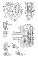
- Fig. 5 shows a pressure measuring device in which the measuring system according to the Figures 1 to 4 is applied.
- the pressure gauge includes a Housing 68, to which a device connection 70 belongs, which acts as a threaded pin is formed and with an external thread and a blind hole 72 formed in the threaded pin is provided.
- the Device connection 70 is used to connect the pressure measuring device a system that guides the substance, the pressure of which is generated by the Pressure measuring device to be measured.
- On the from the device connection 70 opposite side of the housing 68 is in this one transparent lens 74 used.
- the measuring system In the housing 68 and the window 74 enclosed space is the measuring system arranged so that its upper board 4 of the viewing window 74 is facing.
- the dial 12 On the upper board 4 of the measuring system the dial 12 attached, for which two molded on the dial 12 Pin 76 in the mounting holes 10 in the top Board 4 are locked. On the pointer pin 26 is a Pointer 78 inserted, its position over the dial 12 through the lens 74 is visible, so that the the pressure value indicated on the dial 12 by the pointer 78 can be.
- FIG. 5 the housing 68, the dial 12 and the Viewing window 74 shown in section, whereas the measuring system, that has the design according to Figures 1 to 4, in a Fig. 1 corresponding side view is shown.
- the Bourdon tube 48 shown broken away.
- Fig. 5 they are the other End 52 of the tubular spring 48 having half of the tubular spring 48 and the spring end piece 54 because of the broken view the Bourdon tube 48 not shown.
- dash-colon lines is the approach 62, which is before the drawing level of Fig. 5 is located.
- 5 shows the measuring system 2 in one position, which are obtained by rotating the measuring system from that shown in FIG Position about 180 ° around the axis of the pointer shaft 24 results.
- the lower board 6 On the inner wall 80 of the housing 68 are on the mounting holes 10 corresponding projections in the lower board 6 places 82 molded. These are not shown in Fig. 5. However, one of these protrusions 82 is shown in FIG. 6. To do that Attach the measuring system to the housing 68, the lower board 6 attached to the inner wall 80 such that the projections 82nd pass through the mounting holes 10. After that, the tabs 82 expanded and flattened in such a way that it Fig. 6 take the form shown. In this way, the lower one Board 6 riveted to the housing 68 and thereby the entire measuring system attached to the housing.
- a bore 84 is formed, the one End through a channel 86 with the blind hole 72 in connection stands and opens at its other end in the inner wall 80.
- the Bore 84 is sized and positioned to be the connection pin 42 receives sealed when the measuring system is attached to the housing 68 in the manner described above.
- the pressure connection thus produced between the Measuring system and the housing is shown in Fig. 7. 5 is The bore 84 is shown, but not the one inserted into it Connection pin 42.
- the measuring pressure passes through the blind hole 72, the channel 86, the bore 84, the bore 44 in the connecting pin 42 and the spring support 40 into the tubular spring 48.
- the other end 52 thereof and the spring end piece 54 are dependent on the measurement pressure deflected, this deflection by means of the toothed segment 32 and the pinion 28 is transmitted to the pointer 78.
- the connecting pin 42 of the measuring system does not simultaneously connect the device of the pressure measuring device, but rather that the device connection 72 and the connecting pin 42 two different Elements are.
- Pressure measuring device can be modified in that the rear device connection 70 through a so-called radial device connection is replaced by a radial, for example down in Fig. 5, replaced by the housing 68 protruding threaded pin is.
- only channel 86 would have to be another than the course shown.
- the measuring system including its connecting pin 42 need not be modified in this case to be, but can with reference to Figures 1 to 4 Retain the training described.
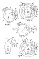
- FIG. 10 shows the lower board 6 of the measuring system in a FIG. 2 similar representation in the state in which it is with assembled the remaining elements of the pointer mechanism to the pointer mechanism 2 becomes.
- the two tabs 8 have already been bent over, and the spring support 40 is in the manner already explained above has been attached to the lower board 6.
- a web 88 is formed on the lower board 6, it merges into approach 62, which in turn merges and is formed in one piece with the spring end piece 54.
- Das Spring end piece 54 and extension 62 are thus in the position in FIG. 10 shown state firmly connected to the lower board 6.
- the spring end piece 54 and the shoulder 62 each have theirs final shape, which they as part of the finished measuring system according to Figures 1 to 4.
- that Spring end piece 54 and the shoulder 62 by means of the web 88 on the lower board 68 relative to the other elements of the lower Circuit board 6, in particular to the bearing hole 20 for the shaft 30 of the toothed segment 32, held in those relative positions, those for the finished measuring system as target positions for unpressurized Bourdon tube are specified.
- the elements forming the extension 62 and the spring end piece 54 are together with the other elements of the lower board 6th punched out of a flat metal sheet and then into the desired one Shape bent.
- the spring end piece 54 shown in Fig. 11 shows that it differs from the state shown in FIG. 10 alone distinguishes that the elements forming the spring end piece have not yet been bent.
- the bottom 56 and the two side walls 58 and 60 of Spring end piece still flat in the plane of the main section of the lower board 6. In this position, the bottom 56 and the two side walls 58 and 60 together with the other elements the lower board 6 has been punched.
- the spring end piece 54 is started from the state shown in Fig.
- the side wall 58 is bent about a bending line 90, the Bottom 56 is bent around a bending line 92 and becomes the side wall 60 bent around a bending line 94, so that the in the figures 10 and 2 shown shape of the spring end piece 54 results.
- the lower board 6 is in its state shown in FIG. 10 with the pointer shaft 24 carrying the pinion 28, which the toothed segment 32 supporting shaft 30, the bias spring 38 and the upper board 4 assembled or assembled to the pointer movement 2.
- the spring end piece 54 and the approach 62 due to its attachment to the lower board 6 components of the pointer mechanism.
- the tubular spring 48 with one end 50 in the Spring carrier 40 inserted and with its other end 52 in the Spring end piece 54 used.
- FIG. 12 shown arrangement of the tubular spring 48 and the pointer mechanism 2, at which at this time the spring end piece 54 and the Approach 62 are attached by means of the web 88. While the Bourdon tube 48 relative to the pointer 2 her shown in Fig.
- Removing the web 88 changes the positions the spring end piece 54 and the shoulder 62 relative to the elements of the pointer mechanism 2, since the removal of the web 88 has no influence on the shape of the tubular spring 48, which thus has the same shape before and after removal of the web 88.
- the spring end piece 54 on the finished measuring system assumes its target position with the same high accuracy, which in the manufacture of the lower board 6 with the molded on it Spring end piece 54 (see Fig. 10) is reached.
- Figures 8 and 9 show similar in Figures 3 and 4 Representations of a further embodiment of the spring support 40.
- the spring support 40 is not a sleeve trained rather than one from the sheet metal of the lower one Board 6 curved cap 96 which is integral with the lower Board 6 is formed and one in plan view according to Fig. 9 has a U-shaped cross section.
- the spring support 40 in shape cap 96 may be similar to that for the spring end 54 has been explained with reference to FIGS. 10 and 11, by bending elements of the stamped part for the lower board getting produced.
- the Cap 96 from the front of the lower board 6 before while on the back of the lower board 6 of this the connecting pin 42 protrudes with the bore 44.
- the connecting pin 42 not molded on the spring support but a separately manufactured one Part inserted into a hole in the bottom board 6 and attached to the lower board 6 by caulking is.
- the connecting pin 42 instead of on the back of the lower board 6 at the bottom 98 of the Cap 96 may be attached.
- the spring support 40 including its modifications are characterized by simple manufacture and small dimensions so that they make it easier to make the measuring system compact. Therefore, the described embodiments of the spring support including their modifications also with advantage be used in measuring systems in which the spring end piece before soldering with the tube spring not to one of the two Boards is attached.
- connection between the toothed segment and the spring end piece without one Drawbar can be a modification of the preferred Embodiment such a tie rod can be provided.
- the L-shaped projection 62 is omitted and is through the tie rod replaced.
- This modification remains unchanged, that the spring end piece is formed by a part that is first attached to one of the boards of the pointer mechanism and only after soldering the other end of the Bourdon tube the spring end piece has been separated.
- Fig. 13 shows the upper board 4, the spring end piece 54 and the shoulder 62 of the measuring system according to Figures 1 to 4, during the Approach 62 still with the upper board 4 by means of a web connected is.
- the approach 62 and the spring end piece 54 are in molded in the same way on the upper board 4, as this with reference to Figures 10 and 11 for the molding on the lower Board 6 has been explained.
- the pointer movement is made from the upper board 4 in its state shown in FIG.
- the spring support 40 on one of the two Boards namely the lower board 6, attached.
- this attachment the spring support is not provided on one of the two boards.
- 14 shows this further exemplary embodiment in a Fig. 12 similar representation during its manufacture.
- 8 and 9 of the measuring system is the spring support 40 with the lower one Circuit board 6 caulked or integrally formed on it, the connection of the spring support 40 to the lower board 46 is produced before the pointer mechanism is assembled.
- the Training provided according to the invention of the spring end piece as a part that before soldering the Bourdon tube to the spring end piece is attached to one of the two boards and after the Solder the Bourdon tube to the spring end piece from this board separated, can also be used for a measuring system that a conventional, with a molded Has device connection provided spring support with which the The pointer mechanism is screwed.
- the assembled Pointer movement, on one of which the spring end piece is attached is screwed to the spring support, after which the Bourdon tube with their ends inserted into the spring support and the spring end piece becomes. After soldering the two ends of the Bourdon tube to the The spring support and the spring end piece separate the spring end piece from the pointer movement.
- the measuring system for a pressure measuring device comprises a pointer mechanism with two boards in which a pointer shaft carrying a pinion and a toothed segment are rotatably mounted. Furthermore, the measuring system comprises an arcuate, metallic tubular spring which is soldered on the one hand to a spring support and on the other hand to a spring end piece. The spring end piece is connected to the toothed segment in such a way that the deflection of the spring end piece is transmitted to the toothed segment due to the measuring pressure.
- the spring end piece is formed by a part rigidly fastened to one of the two boards before the tube spring is soldered to the spring end piece and separated from this board after the tube spring is soldered to the spring end piece.
- the measuring system for a pressure measuring device comprises a pointer mechanism (2) with two plates (4, 6) in which a pointer shaft (24) carrying a pinion (28) and a toothed segment (32) are rotatably mounted.
- the measuring system further comprises an arcuately curved, metallic tubular spring (48) which is soldered on the one hand to a spring support (40) and on the other hand to a spring end piece (54).
- the spring end piece (54) is connected to the toothed segment (32) in such a way that the deflection of the spring end piece (54) is transmitted to the toothed segment (32) due to the measuring pressure.
- the spring end piece (54) is rigidly fastened to one of the two boards (4, 6) by one before the tube spring (48) is soldered to the spring end piece (54) and after the tube spring (48) is soldered to the spring end piece (54) part of this board.
- the spring end piece (54) is manufactured as a part which is firmly connected to one of the two boards (4, 6).
- the Bourdon tube (48) is soldered to the spring end piece (54) while it is still rigidly attached to the circuit board. Only then is the spring end piece (54) separated from the board.
- the spring support (40) is preferably formed or attached to one of the two boards (4, 6). The spring end piece (54) assumes its desired position with respect to the pointer mechanism (2) with high accuracy.
Abstract
Description
Die Erfindung bezieht sich auf ein Meßsystem für ein Druckmeßgerät gemäß dem Oberbegriff von Patentanspruch 1 sowie ein Verfahren zur Herstellung eines Meßsystems für ein Druckmeßgerät gemäß dem Oberbegriff von Patentanspruch 15.The invention relates to a measuring system for a pressure measuring device according to the preamble of claim 1 and a method for the production of a measuring system for a pressure measuring device according to the preamble of claim 15.
Ein Meßsystem mit dem Merkmalen des Oberbegriffs von Patentanspruch 1 sowie ein Verfahren mit den Merkmalen des Oberbegriffs von Patentanspruch 15 sind bekannt. Das bekannte Meßsystem kann mit einem auf die vordere Platine aufgesetzten Zifferblatt und einem auf den Zeigerzapfen aufgesetzten Zeiger versehen sein. Die Einheit aus dem Meßsystem, dem Zifferblatt und dem Zeiger kann in einem Gehäuse angeordnet sein, das vor dem Zifferblatt eine Sichtscheibe trägt, so daß diese Elemente dann ein Druckmeßgerät bilden.A measuring system with the features of the preamble of claim 1 and a method with the features of the preamble of claim 15 are known. The known measuring system can with a dial placed on the front plate and be provided with a pointer placed on the pointer pin. The unit from the measuring system, the dial and the pointer can be arranged in a case in front of the dial carries a lens, so that these elements then a pressure gauge form.
Bei dem bekannten Meßsystem besteht der Federträger üblicherweise aus einem quaderförmigen, metallischen Bauteil, an dem einerseits ein durchbohrter Geräteanschluß angeformt und andererseits eine Nut ausgebildet ist. Der häufig als Gewindezapfen ausgebildete Geräteanschluß dient zum Anschließen des Druckmeßgeräts an ein System, in dem der Meßdruck, d.h. der zu messende Druck, herrscht und steht in Verbindung mit der Nut. Das eine Ende der Rohrfeder ist in die Nut eingesetzt und dort mit dem Federträger verlötet. Mit dem anderen Ende der Rohrfeder ist das Federendstück derart verlötet, daß das andere Ende druckdicht geschlossen ist. Der Meßdruck gelangt durch den Geräteanschluß in die gekrümmte Rohrfeder, die in Abhängigkeit von der Höhe des Meßdrucks aufgeweitet wird, so daß ihr anderes Ende und somit das Federendstück ausgelenkt werden. Das Federendstück ist bei dem bekannten Meßsystem mittels einer Zugstange gelenkig mit dem Hebelabschnitt des Zahnsegmentes verbunden, so daß die Auslenkung des Federendstücks in eine Drehung der Zeigerwelle und somit des Zeigers umgewandelt wird. Am Zifferblatt zeigt der Zeiger den herrschenden Meßdruck an.In the known measuring system, the spring support usually consists from a cuboid, metallic component on which on the one hand a pierced device connection is formed and on the other hand a groove is formed. Often as a threaded pin trained device connection is used to connect the pressure gauge to a system in which the measuring pressure, i.e. the one to be measured Pressure prevails and is connected to the groove. The one The end of the Bourdon tube is inserted into the groove and there with the Spring support soldered. With the other end of the Bourdon tube is the spring end piece is soldered in such a way that the other end is pressure-tight closed is. The measuring pressure passes through the device connection into the curved Bourdon tube depending on the Height of the measuring pressure is expanded so that its other end and thus the spring end piece can be deflected. The spring end piece is in the known measuring system by means of a tie rod hinged to the lever section of the toothed segment, so that the deflection of the spring end piece in a rotation of the pointer shaft and thus the pointer is converted. On the dial the pointer shows the prevailing measuring pressure.
Im Zuge der Herstellung des bekannten Meßsystems wird das eine Ende der Rohrfeder am Federträger angelötet und wird das Federendstück mit dem anderen Ende der Rohrfeder verlötet. Parallel dazu wird das Zeigerwerk montiert. Das montierte Zeigerwerk wird dann am Federträger befestigt. Dies geschieht üblicherweise dadurch, daß die untere Platine des Zeigerwerks am Federträger angeschraubt wird. Dabei muß darauf geachtet werden, daß die Rohrfeder und das Federendstück möglichst genau ihre Sollstellungen bezüglich des Zeigerwerks, insbesondere bezüglich der Drehachse des Zahnsegmentes, einnehmen, da von der Genauigkeit, mit der diese Sollstellungen eingehalten werden, die Genauigkeit der Druckmessung und der Druckanzeige beeinflußt wird. Nachdem das Zeigerwerk am Federträger befestigt worden ist, wird die Zugstange gelenkig sowohl mit dem Federendstück als auch mit dem Hebelabschnitt des Zahnsegmentes verbunden, damit die Auslenkung des Federendstücks zum Hebelabschnitt übertragen werden kann.In the course of the manufacture of the known measuring system, this becomes one End of the Bourdon tube is soldered to the spring support and the spring end piece soldered to the other end of the Bourdon tube. Parallel the pointer mechanism is installed. The assembled pointer mechanism is then attached to the spring support. This usually happens in that the lower plate of the pointer mechanism on the spring support is screwed on. Care must be taken that the Bourdon tube and the spring end piece as precisely as possible their target positions with regard to the pointer mechanism, in particular with regard to the axis of rotation of the tooth segment, because of the accuracy, with which these target positions are maintained, the accuracy the pressure measurement and the pressure display becomes. After the pointer has been attached to the spring support is, the tie rod is articulated both with the spring end piece as well as connected to the lever section of the tooth segment, thus the deflection of the spring end piece to the lever section can be transferred.
Aufgrund der vorstehend beschriebenen Verfahrensschritte bei der Herstellung des bekannten Meßsystems ist diese Herstellung vergleichsweise arbeitsintensiv und aufwendig. Zudem ist nicht gewährleistet, daß die Rohrfeder und das Federendstück ihre geometrischen Sollstellungen bezüglich des Zeigerwerks einnehmen, was, je nach den Genauigkeitsanforderungen an das Meßsystem, eine mehr oder weniger aufwendige Justierung des Meßsystems notwendig machen kann.Due to the process steps described above the manufacture of the known measuring system is this manufacture comparatively labor-intensive and complex. Besides, it is not ensures that the Bourdon tube and the spring end piece their assume geometric target positions with respect to the pointer mechanism, what, depending on the accuracy requirements of the measuring system, a more or less complex adjustment of the measuring system can make necessary.
Ein Meßsystem mit den Merkmalen des Oberbegriffs von Patentanspruch 1 sowie ein Verfahren mit dem Merkmalen des Oberbegriffs von Patentanspruch 15 sind auch durch die Veröffentlichung DE 23 54 473 C2 bekannt. Bei diesem bekannten Meßsystem ist der Federträger entweder als mit der oberen Platine verschraubtes Metallstück, in das das eine Ende der Rohrfeder luftdicht eingespannt ist, oder als Blechlappen ausgebildet, der mit der oberen Platine einstückig ausgebildet oder an dieser angeschraubt ist. Wenn der Federträger als Blechlappen ausgebildet ist, wird im Zuge der Herstellung dieses bekannten Meßsystems das eine Ende der Rohrfeder auf den Blechlappen geschoben. Außerdem wird ein der Zufuhr des Meßdrucks dienendes Röhrchen in das eine Ende der Rohrfeder eingeschoben. Der Blechlappen, das Röhrchen und das eine Ende der Rohrfeder werden schließlich miteinander verschweißt. Wenn bei diesem bekannten Meßsystem der Federträger an der Platine des Zeigerwerks angeschraubt wird, sind die Herstellung des Meßsystems und seine Justierung ähnlich aufwendig wie bei dem zuvor beschriebenen bekannten Meßsystem. Wenn der den Federträger bildende Blechlappen einstückig mit der oberen Platine ausgebildet ist, sind zwar das Verbinden des einen Endes der Rohrfeder mit dem Federträger und die Herstellung einer starren Verbindung dieses Endes der Rohrfeder mit dem Zeigerwerk zu einem Schritt zusammengefaßt. Das Federendstück nimmt jedoch bezüglich des Zeigerwerks eine nicht hinreichend genau definierte Stellung ein, so daß die Genauigkeit der Druckanzeige gering ist bzw. eine Erhöhung der Anzeigegenauigkeit nur durch erhöhten Justierungsaufwand erzielt werden kann.A measuring system with the features of the preamble of claim 1 and a method with the features of the preamble of claim 15 are also by the publication DE 23 54 473 C2 known. In this known measuring system Spring support either as screwed to the top board Metal piece in which one end of the Bourdon tube is clamped airtight is, or formed as a sheet metal tab with the upper board formed in one piece or screwed to it is. If the spring support is designed as a sheet metal tab is in the course of the production of this known measuring system pushed one end of the Bourdon tube onto the sheet metal tab. Moreover a tube serving to supply the measuring pressure in inserted one end of the Bourdon tube. The sheet metal rag Tubes and one end of the Bourdon tube eventually become welded together. If with this known measuring system the spring support is screwed to the circuit board of the pointer mechanism is the manufacture of the measuring system and its adjustment similarly expensive as in the previously described known Measuring system. If the sheet metal tab forming the spring support is in one piece is formed with the upper board, that is Connect one end of the Bourdon tube to the spring support and making a rigid connection to this end of the Bourdon tube combined into a step with the pointer mechanism. The However, spring end piece does not take one with respect to the pointer mechanism sufficiently well-defined position, so that the accuracy the pressure display is low or an increase in the display accuracy only achieved through increased adjustment effort can be.
Der Erfindung liegt die Aufgabe zugrunde, das gattungsgemäße Meßsystem dahingehend weiterzubilden, daß es verringerten Justierungsaufwand erfordert. Dies heißt mit anderen Worten, daß es schon ohne Justierung eine vergleichsweise hohe Anzeigegenauigkeit haben soll. Ferner soll die Herstellung des zu schaffenden Meßsystems vereinfacht sein.The invention has for its object the generic To further develop the measuring system in such a way that it reduces the adjustment effort required. In other words, this means that a comparatively high display accuracy even without adjustment should have. Furthermore, the manufacture of the to be created Measuring system be simplified.
Der Erfindung liegt ferner die Aufgabe zugrunde, das gattungsgemäße Verfahren dahingehend weiterzubilden, daß die Herstellung des Meßsystems vereinfacht ist und mit geringem Herstellungsaufwand ein vergleichsweise genau anzeigendes Meßsystem geschaffen wird.The invention is also based on the object of the generic type Process further in that the manufacture the measuring system is simplified and with little manufacturing effort a comparatively accurate measuring system is created.
Hinsichtlich des Meßsystems wird die Aufgabe durch das Meßsystem gemäß Patentanspruch 1 gelöst. Dieses zeichnet sich dadurch aus, daß das Federendstück durch ein vor dem Verbinden der Rohrfeder mit dem Federendstück an einer der beiden Platinen befestigtes und nach der Anbringung der Rohrfeder an dem Federendstück von dieser Platine abgetrenntes Teil gebildet ist. Bei dem erfindungsgemäßen Meßsystem ist das das Federendstück bildende Teil vor dem Verbinden mit der Rohrfeder an einer der beiden Platinen befestigt. Das Federendstück nimmt dadurch bezüglich der Elemente des Zeigerwerks, insbesondere bezüglich der Drehachse des Zahnsegmentes, eine definierte Stellung ein, die im Zuge der Herstellung der Platine, an der das das Endstück bildende Teil vor dem Abtrennen befestigt ist, mit hoher Genauigkeit in Übereinstimmung mit der Sollstellung des Federendstücks gebracht werden kann. Während des starren Verbindens des anderen Endes der Rohrfeder mit dem Federendstück wird letzteres aufgrund seiner Befestigung an der Platine praktisch genau in seiner Sollstellung gehalten, die das Federendstück dann zwangsläufig auch noch nach der Trennung von der Platine einnimmt. Auf diese Weise ist ein Meßsystem geschaffen, das schon ohne Justierung eine vergleichsweise hohe Anzeigegenauigkeit aufweist.With regard to the measuring system, the task is performed by the measuring system solved according to claim 1. This is characterized by it that the spring end piece by a before connecting the Bourdon tube with the spring end piece on one of the two boards attached and after attaching the Bourdon tube to the Spring end piece formed from this board part is. In the measuring system according to the invention, this is the spring end piece forming part before connecting to the Bourdon tube on one of the two boards attached. This takes the spring end piece with regard to the elements of the pointer mechanism, in particular with regard to the axis of rotation of the tooth segment, a defined position one, in the course of the manufacture of the circuit board on which the the part forming the end piece is attached before being separated, with high accuracy in accordance with the target position of the Spring end piece can be brought. During the rigid connection the other end of the Bourdon tube with the spring end piece the latter becomes practical due to its attachment to the board held exactly in its target position, which is the spring end piece then inevitably even after the separation from the Occupies board. In this way a measuring system is created a comparatively high display accuracy even without adjustment having.
Gemäß den Patentansprüchen 5 und 6 kann vorgesehen sein, daß
der Federträger an einer der beiden Platinen befestigt ist, daß
diejenige Platine, an der der Federträger befestigt ist, aus
einem Metallblech besteht und daß der Federträger einstückig
mit dieser Platine ausgebildet ist und in Form einer Kappe mit
U-förmigem Querschnitt aus dem Metallblech gebogen ist. Alternativ
kann gemäß den Patentansprüchen 5 und 9 vorgesehen sein,
daß der Federträger an einer der beiden Platinen befestigt ist,
daß er als Hülse ausgebildet ist, die einen in ihrer Längsrichtung
verlaufenden Schlitz zur Aufnahme des einen Endes der
Rohrfeder aufweist, und daß an der Hülse ein mit einer Bohrung
versehener Anschlußzapfen angeformt ist, dessen Bohrung in den
Innenraum der Hülse mündet. Gemäß diesen beiden vorstehend genannten
Alternativen ist der Federträger besonders kompakt und
auf besonders zweckmäßige Weise in das Zeigerwerk integriert.
Diese beiden alternativen Ausbildungen des Federträgers sind
bei einem Meßsystem sinnvoll auch dann anwendbar, wenn das Federendstück
nicht durch ein vor dem starren Verbinden mit dem
Federendstück an einer der beiden Platinen befestigtes Teil gebildet
ist. In Verbindung mit dem kennzeichnenden Merkmal von
Anspruch 1 hat die Befestigung des Federträgers an einer der
beiden Platinen den Vorteil, daß der Federträger während des
Verbindens des anderen Endes der Rohrfeder mit dem Federendstück
als Vorrichtung zur Lagefixierung des einen Endes der
Rohrfeder dienen kann und somit eine separate Fixiervorrichtung
zu diesem Zweck nicht notwendig ist.According to
Gemäß Patentanspruch 12 kann vorgesehen sein, daß das Zeigerwerk
eine Vorspannfeder aufweist, die auf das Zahnsegment eine
Vorspannkraft ausübt, und daß mit dem Federendstück starr ein
Anschlag verbunden ist, an dem der Hebelabschnitt des Zahnsegmentes
aufgrund der Vorspannkraft der Vorspannfeder anliegt.
Bei dieser Ausbildung folgt der Hebelabschnitt des Zahnsegmentes
stets der Bewegung bzw. Auslenkung des Federendstücks, so
daß sich eine Zugstange zur Herstellung der Verbindung zwischen
dem Federendstück und dem Hebelabschnitt des Zahnsegmentes erübrigt.
Diese zugstangenlose Verbindung kann vorteilhaft auch
bei Meßsystemen angewendet werden, bei denen das Federendstück
nicht durch ein vor dem Verbinden der Rohrfeder mit dem Federendstück
an einer der beiden Platinen befestigtes Teil gebildet
ist.According to
Hinsichtlich des Verfahrens wird die Aufgabe durch das Verfahren gemäß Patentanspruch 16 gelöst. Gemäß dem erfindungsgemäßen Verfahren ist vorgesehen, daß das Federendstück als mit einer der beiden Platinen fest verbundenes Teil gefertigt wird, so daß das Federendstück Bestandteil des montierten Zeigerwerks ist, daß das Federendstück in Verbindung mit dem Hebelabschnitt gebracht wird, bevor das andere Ende der Rohrfeder mit dem Federendstück starr verbunden wird, daß das andere Ende der Rohrfeder mit dem Federendstück starr verbunden wird, während dieses an der Platine befestigt ist, und daß nach dem Verbinden der Rohrfeder mit dem Federendstück das Federendstück von der Platine getrennt wird. Durch dieses Vorgehen wird auf einfache Weise ein Meßsystem geschaffen, das bereits ohne Justierung eine vergleichsweise hohe Anzeigegenauigkeit hat, wie dies bereits vorstehend im Zusammenhang mit dem Meßsystem nach Anspruch 1 des Patentes erläutert wurde.With regard to the procedure, the task is accomplished by the procedure solved according to claim 16. According to the invention The method provides that the spring end piece be used as a of the two boards is firmly connected part, so that the spring end piece is part of the assembled pointer mechanism is that the spring end piece in connection with the lever portion is brought before the other end of the Bourdon tube with the spring end piece is rigidly connected to the other end of the Bourdon tube is rigidly connected to the spring end piece while this attached to the board, and that after connecting the Bourdon tube with the spring end piece the spring end piece of the Board is separated. This will make it easy Way created a measuring system that already without adjustment a has comparatively high display accuracy, like this already above in connection with the measuring system according to claim 1 of the patent was explained.
In vorteilhafter Weiterbildung des erfindungsgemäßen Verfahrens kann vorgesehen sein, daß der Federträger an einer der Platinen des Zeigerwerks angeformt oder befestigt wird, bevor er mit dem einen Ende der Rohrfeder verbunden wird, so daß der Federträger Bestandteil des montierten Zeigerwerks ist, und daß das eine Ende der Rohrfeder in den Federträger eingesetzt ist, während das andere Ende der Rohrfeder mit dem Federendstück starr verbunden wird. In diesem Fall ist durch den Federträger die Lage der Rohrfeder während des Verbindens mit dem Federendstück vorgegeben und fixiert, so daß zu diesem Zweck keine zusätzlichen Fixiervorrichtungen erforderlich sind.In an advantageous development of the method according to the invention can be provided that the spring support on one of the boards the pointer mechanism is molded or attached before it with the one end of the Bourdon tube is connected so that the spring support Part of the assembled movement is, and that the one End of the Bourdon tube is inserted into the spring support while the other end of the tube spring is rigidly connected to the spring end piece becomes. In this case, the position is due to the spring support of the Bourdon tube during connection to the spring end piece and fixed, so that for this purpose no additional Fixing devices are required.
Ferner kann in weiterer vorteilhafter Ausbildung des erfindungsgemäßen Verfahrens vorgesehen sein, daß das Verbinden des einen Endes der Rohrfeder mit dem Federträger und das Verbinden des anderen Endes der Rohrfeder mit dem Federendstück gleichzeitig erfolgen. Bei diesem Vorgehen sind die herkömmlichen Schritte des Verlötens der Rohrfeder mit dem Federträger, des Verlötens der Rohrfeder mit dem Federendstück und des starren Verbindens des Zeigerwerks mit der Rohrfeder zu einem einzigen Herstellungsschritt zusammengefaßt. Furthermore, in a further advantageous embodiment of the invention The method should be provided that connecting the one end of the Bourdon tube with the spring support and connecting the other end of the Bourdon tube with the spring end piece at the same time respectively. This is the conventional approach Steps of soldering the Bourdon tube to the spring support, the Soldering the Bourdon tube with the spring end and the rigid Connecting the pointer mechanism with the Bourdon tube into a single one Manufacturing step summarized.
Weitere vorteilhafte Ausgestaltungen der Erfindung sind in den Unteransprüchen gekennzeichnet.Further advantageous embodiments of the invention are in the Subclaims marked.
Ausführungsbeispiele der Erfindung werden im folgenden anhand der Zeichnungen näher erläutert. Es zeigen:
- Fig. 1
- eine Seitenansicht eines Ausführungsbeispiels des erfindungsgemäßen Meßsystems, wobei eine Rohrfeder des Meßsystems teilweise weggebrochen dargestellt ist;
- Fig. 2
- eine Vordersicht des Meßsystem gemäß Fig. 1 bei Betrachtung in Richtung eines Pfeiles A in Fig. 1;
- Fig. 3
- eine Ansicht eines Federträgers des Meßsystems gemäß den Figuren 1 und 2 bei Betrachtung in Richtung eines Pfeiles B in Fig. 2;
- Fig. 4
- eine Draufsicht zu Fig. 3;
- Fig. 5
- eine Schnittdarstellung eines Druckmeßgerätes mit dem Meßsystem gemäß den Figuren 1 bis 4, wobei das Meßsystem in Seitenansicht dargestellt ist und dessen Rohrfeder teilweise weggebrochen dargestellt ist;
- Fig. 6
- eine ausschnittsweise Schnittdarstellung zur Erläuterung der Befestigung des Meßsystems des Druckmeßgerätes gemäß Fig. 5 an dessen Gehäuse;
- Fig. 7
- eine ausschnittsweise Schnittdarstellung zur Erläuterung eines Druckanschlusses des Druckmeßgerätes gemäß Fig. 5;
Figuren 8 und 9- den Figuren 3 und 4 entsprechende Darstellungen einer weiteren Ausführungsform des Federträgers;
- Fig. 10
- eine untere Platine des Meßsystems gemäß den Figuren 1 und 2 zu einem Zeitpunkt vor der Montage von dessen Zeigerwerk;
- Fig. 11
- die unter Platine gemäß Fig. 10 während ihrer Herstellung;
- Fig. 12
- das Meßsystem gemäß den Figuren 1 und 2 während eines Herstellungsschrittes desselben;
- Fig. 13
- eine obere Platine für eine abgewandelte Ausführungsform des Verfahrens zur Herstellung des Meßsystems gemäß den Figuren 1 und 2; und
- Fig. 14
eine Figur 12 entsprechende Darstellung eines Meßsystems gemäß einem weiteren Ausführungsbeispiel.
- Fig. 1
- a side view of an embodiment of the measuring system according to the invention, wherein a Bourdon tube of the measuring system is shown partially broken away;
- Fig. 2
- a front view of the measuring system of Figure 1 when viewed in the direction of an arrow A in Fig. 1.
- Fig. 3
- a view of a spring support of the measuring system according to Figures 1 and 2 when viewed in the direction of an arrow B in Fig. 2;
- Fig. 4
- a plan view of Fig. 3;
- Fig. 5
- a sectional view of a pressure measuring device with the measuring system according to Figures 1 to 4, wherein the measuring system is shown in side view and the Bourdon tube is shown partially broken away;
- Fig. 6
- a partial sectional view for explaining the attachment of the measuring system of the pressure measuring device according to FIG 5 to the housing.
- Fig. 7
- a partial sectional view for explaining a pressure connection of the pressure measuring device according to FIG. 5;
- Figures 8 and 9
- Figures 3 and 4 corresponding representations of another embodiment of the spring support;
- Fig. 10
- a lower board of the measuring system according to Figures 1 and 2 at a time before the assembly of the pointer movement;
- Fig. 11
- the under board according to Figure 10 during its manufacture.
- Fig. 12
- the measuring system according to Figures 1 and 2 during the same manufacturing step;
- Fig. 13
- an upper board for a modified embodiment of the method for producing the measuring system according to Figures 1 and 2; and
- Fig. 14
- a representation corresponding to Figure 12 of a measuring system according to another embodiment.
In den Figuren sind gleiche bzw. einander entsprechende Elemente jeweils mit demselben Bezugszeichen bezeichnet.The figures show the same or corresponding elements each designated with the same reference number.
Das in den Figuren 1 bis 4 dargestellte Ausführungsbeispiel eines
Meßsystems umfaßt ein sogenanntes Zeigerwerk 2, das als
tragende Elemente eine obere Platine 4 und eine untere Platine
6 aufweist. Wie insbesondere Fig. 1 zeigt, sind die ober Platine
4 und die untere Platine 6 mit Abstand voneinander und parallel
zueinander angeordnet. Die obere Platine 4 ist eben, besteht
aus einem Metallblech und ist als Stanzteil hergestellt.
Die untere Platine 6 weist einen ebenen Hauptabschnitt auf, besteht
ebenfalls aus einem Metallblech und ist durch Stanzen und
Umbiegen hergestellt. Am ebenen Hauptabschnitt der unteren Platine
6 sind zwei unter ungefähr 90° umgebogene, zur oberen Platine
4 gerichtete Lappen 8 angeformt, an denen die obere Platine
4 anliegt. Jeder Lappen 8 weist einen Ansatz 9 auf, der
durch eine entsprechende Öffnung in der oberen Platine 4 ragt
und verstemmt ist. Auf diese Weise sind die obere Platine 4 und
die unter Platine 6 fest miteinander verbunden.The embodiment shown in Figures 1 to 4 of a
Measuring system comprises a so-called
Die obere Platine 4 ist mit zwei Befestigungslöchern 10 versehen,
die zur Befestigung eines Zifferblattes 12 an der oberen
Platine 4 dienen (siehe Fig. 5). Ferner sind in der oberen Platine
4 ein Lagerloch 14 und ein Lagerloch 16 ausgebildet. In
der unteren Platine sind zwei Montagelöcher 18 sowie zwei Lagerlöcher
20 und 22 ausgebildet (siehe Fig. 10).The
In dem Lagerloch 16 und dem Lagerloch 22 ist eine Zeigerwelle
24 drehbar gelagert. Die Zeigerwelle 24 weist an ihrem einen
Ende einen Zeigerzapfen 26 auf, der in in Fig. 1 gezeigter Weise
von der Platine 4 vorsteht. Weil die Platine 4 diejenige
ist, von der der Zeigerzapfen 26 vorsteht, wird sie im Rahmen
der vorstehenden Beschreibung und Ansprüche als "obere Platine"
bezeichnet. Mit der Zeigerwelle 24 fest verbunden ist ein zwischen
den beiden Platinen 4 und 6 angeordnetes Ritzel 28.There is a pointer shaft in the bearing hole 16 and the bearing hole 22
24 rotatably mounted. The
In den Lagerlöchern 14 und 20 ist eine Welle 30 eines zwischen
den beiden Platinen 4 und 6 angeordneten Zahnsegmentes 32 gelagert.
Beim dargestellten Ausführungsbeispiel ist das Zahnsegment
32 als zweiarmiger Hebel ausgebildet, dessen einer Arm
durch einen verzahnten Abschnitt 34 gebildet ist und dessen anderer
Arm durch einen Hebelabschnitt 36 gebildet ist. Der verzahnte
Abschnitt 34 und der Hebelabschnitt 36 liegen in einer
zu den Ebenen der Platinen 4 und 6 parallelen Ebene. In dieser
Ebene ist der Hebelabschnitt 36 U-förmig gekrümmt. Der verzahnte
Abschnitt 34 kämmt mit dem Ritzel 28.In the bearing holes 14 and 20, a
Zwischen den beiden Platinen 4 und 6 ist ferner eine als Spiralfeder
ausgebildete Vorspannfeder 38 angeordnet, deren eines
Ende mit der Zeigerwelle 24 verbunden ist und deren anderes Ende
in nicht dargestellter Weise an der unteren Platine 6 festgelegt
ist. Die Vorspannfeder 38 übt ein Vorspannmoment im Gegenuhrzeigersinn
in Fig. 2 auf das Ritzel 28 aus, das aufgrund
des Eingriffs zwischen dem Ritzel 28 und dem verzahnten Abschnitt
34 zu einer elastischen Vorspannkraft am Zahnsegment 32
führt, die dieses im Uhrzeigersinn in Fig. 2 zu drehen versucht.Between the two
An der unteren Platine 6 ist ein Federträger 40 in Form einer
Hülse 41 befestigt. Am in Fig. 3 unteren Ende der Hülse 41 ist
ein Anschlußzapfen 42 mit einer mittigen Bohrung 44 angeformt,
die in den Innenraum der Hülse mündet. Die Hülse 41 sitzt auf
der in Fig. 2 sichtbaren Vorderseite der unteren Platine 6, und
der Anschlußzapfen 42 verläuft durch ein Loch in der unteren
Platine 6, so daß er von deren Rückseite vorsteht, wie dies in
den Figuren 1 und 3 gezeigt ist. Die den Federträger 40 bildende
Hülse 41 ist durch Verstemmen an der unteren Platine befestigt.
Die Hülse 41 ist an ihrem in Fig. 3 oberen Ende offen
und weist einen in ihrer Längsrichtung verlaufenden Schlitz 46
auf.On the
Das Meßsystem weist zusätzlich zu dem vorstehend erläuterten
Zeigerwerk 2 und dem mit dem Zeigerwerk integrierten Federträger
40 eine bogenförmig gekrümmte, metallische Rohrfeder 48
auf. Deren eines Ende 50 erstreckt sich durch den Schlitz 46 in
den Innenraum der Hülse 41 und ist mit dem durch die Hülse 41
gebildeten Federträger 40 durch Verlöten starr verbunden. Das
Lot ist in Fig. 2 nicht dargestellt. Durch die Bohrung 46 im
Anschlußzapfen 42 und den Innenraum der Hülse 41 kann der Meßdruck
in das Innere der Rohrfeder 48 gelangen. Ansonsten ist
die Verbindung zwischen dem einen Ende 50 der Rohrfeder 48 und
dem Federträger 40 druckdicht. Auf diese Weise ist das eine Ende
50 der Rohrfeder 48 starr mit dem Zeigerwerk 2 verbunden und
in seiner Lage relativ zum Zeigerwerk 2 festgelegt.The measuring system has in addition to that explained above
Die Rohrfeder 48 erstreckt sich in einem Bogen von ungefähr
270° um das Zeigerwerk 2, wie dies in Fig. 2 gezeigt ist. An
ihrem anderen Ende 52 trägt die Rohrfeder 48 ein Federendstück
54, das mit dem anderen Ende 52 dieses dicht schließend durch
Verlöten starr verbunden ist, wobei wiederum das Lot in Fig. 2
nicht dargestellt ist. Das Federendstück 54 ist durch ein Teil
gebildet, das vor dem Verlöten mit dem Ende 52 an der unteren
Platine 6 befestigt war und nach diesem Verlöten von der unteren
Platine 6 abgetrennt worden ist, wie dies im folgenden noch
näher erläutert werden wird.The
Vorstehend ist angegeben, daß das eine Ende 50 der Rohrfeder 48
mit dem Federträger 40 verlötet ist und daß das andere Ende 52
der Rohrfeder 48 mit dem Federendstück 54 verlötet ist. Dabei
handelt es sich bei dem Verlöten um die bei dem beschriebenen
Ausführungsbeispiel gewählte Art der Herstellung der starren
Verbindung der beiden Enden der Rohrfeder 48 mit dem Federträger
40 bzw. dem Federendstück 54. Diese Verbindung ist jedoch
nicht notwendigerweise eine Lötverbindung. Vielmehr kommen auch
andere Arten der stoffschlüssigen Verbindung, insbesondere eine
Schweißverbinung, in Frage. Dies gilt für die gesamte folgende
Beschreibung einschließlich der Erläuterung des Verfahrens zur
Herstellung des Meßsystems. Auch wenn im folgenden der Begriff
"Löten" und sinnverwandte Ausdrücke benutzt werden, kommen
stets andere Verfahren zur Herstellung einer starren stoffschlüssigen
Verbindung in Frage.It is stated above that one
Beim dargestellten Ausführungsbeispiel ist das Federendstück 54
als Kappe ausgebildet, die einen Boden 56 und zwei Seitenwände
58 und 60 aufweist. Der Boden 56 und die beiden Seitenwände 58
und 60 bestehen aus demselben Metallblech wie die untere Platine
6 und sind durch Umbiegen der Seitenwände 58 und 60 sowie
des Bodens 56 relativ zueinander zu der Kappe geformt worden.
Mit der einen Seitenwand 60 ist einstückig ein L-förmiger Ansatz
62 ausgebildet, dessen von dem Federendstück 54 ausgehender
Schenkel 64 parallel zu den Ebenen der beiden Platinen 4
und 6 verläuft. Der andere Schenkel 66 des Ansatzes 62 erstreckt
sich im wesentlichen senkrecht zu den Ebenen der beiden
Platinen 4 und 6 und bildet einen Anschlag für den U-förmigen
Hebelabschnitt 36. Das freie Ende des Hebelabschnitts 36 liegt
aufgrund der von der Vorspannfeder 38 ausgeübten Vorspannkraft
auf der dem Federendstück 54 zugewandten Seite des Schenkels 66
an.In the illustrated embodiment, the
In den Figuren 1 und 2 ist das Meßsystem im drucklosen Zustand
dargestellt. Wenn in der Rohrfeder 48 der Meßdruck wirkt und
höher als der von außen auf die Rohrfeder 48 wirkende Umgebungsdruck
ist, wird die Rohrfeder 48 aufgeweitet und wird dadurch
deren anderes Ende 52 in Richtung eines Pfeiles M in Fig.
2 ausgelenkt. An dieser Auslenkung nimmt das Federendstück 54
teil, was zur Folge hat, daß der Schenkel 66 das Zahnsegment 32
im Gegenuhrzeigersinn in Fig. 2 schwenkt, so daß die Zeigerwelle
24 entsprechend der Auslenkung gedreht wird. In Fig. 2 ist
zusätzlich der verzahnte Abschnitt 34 in seiner dem Nenndruck
des Meßsystems entsprechenden Endstellung 34' dargestellt. In Figures 1 and 2, the measuring system is in a depressurized state
shown. If the measuring pressure acts in the
Fig. 5 zeigt ein Druckmeßgerät, bei dem das Meßsystem gemäß den
Figuren 1 bis 4 angewendet ist. Das Druckmeßgerät umfaßt ein
Gehäuse 68, zu dem ein Geräteanschluß 70 gehört, der als Gewindezapfen
ausgebildet ist und mit einem Außengewinde und einem
im Gewindezapfen ausgebildeten Sackloch 72 versehen ist. Der
Geräteanschluß 70 dient zum Anschließen des Druckmeßgerätes an
ein System, das den Stoff führt, dessen Druck mittels des
Druckmeßgerätes gemessen werden soll. Auf der vom Geräteanschluß
70 abgewandten Seite des Gehäuses 68 ist in dieses eine
durchsichtige Sichtscheibe 74 eingesetzt. In dem vom Gehäuse 68
und der Sichtscheibe 74 umschlossenen Raum ist das Meßsystem
derart angeordnet, daß seine obere Platine 4 der Sichtscheibe
74 zugewandt ist. An der oberen Platine 4 des Meßsystems ist
das Zifferblatt 12 befestigt, wozu zwei am Zifferblatt 12 angeformte
Zapfen 76 in die Befestigungslöcher 10 in der oberen
Platine 4 eingerastet sind. Auf den Zeigerzapfen 26 ist ein
Zeiger 78 gesteckt, dessen Stellung über dem Zifferblatt 12
durch die Sichtscheibe 74 hindurch sichtbar ist, so daß der auf
dem Zifferblatt 12 vom Zeiger 78 angezeigte Druckwert abgelesen
werden kann.Fig. 5 shows a pressure measuring device in which the measuring system according to the
Figures 1 to 4 is applied. The pressure gauge includes a
In Fig. 5 sind das Gehäuse 68, das Zifferblatt 12 und die
Sichtscheibe 74 im Schnitt dargestellt, wogegen das Meßsystem,
das die Ausbildung gemäß den Figuren 1 bis 4 hat, in einer Fig.
1 entsprechenden Seitenansicht gezeigt ist. Dabei ist die Rohrfeder
48 weggebrochen dargestellt. In Fig. 5 sind die das andere
Ende 52 der Rohrfeder 48 aufweisende Hälfte der Rohrfeder 48
sowie das Federendstück 54 wegen der abgebrochenen Darstellung
der Rohrfeder 48 nicht gezeigt. Mit Strich-Doppelpunkt-Linien
ist jedoch der Ansatz 62, der sich vor der Zeichenebene von
Fig. 5, befindet eingezeichnet. Wie in Fig. 5 erkennbar ist,
ist das Meßsystem 2 in Fig. 5 in einer Position dargestellt,
die sich durch Drehung des Meßsystems aus der in Fig. 1 gezeigten
Stellung um ungefähr 180° um die Achse der Zeigerwelle 24
ergibt. 5, the
An der Innenwand 80 des Gehäuses 68 sind an den Befestigungslöchern
10 in der unteren Platine 6 entsprechenden Stellen Vorsprünge
82 angeformt. Diese sind in Fig. 5 nicht dargestellt.
Einer dieser Vorsprünge 82 ist jedoch in Fig. 6 gezeigt. Um das
Meßsystem am Gehäuse 68 zu befestigen, wird die untere Platine
6 derart an die Innenwand 80 angesetzt, daß die Vorsprünge 82
durch die Befestigungslöcher 10 treten. Danach werden die Vorsprünge
82 derart aufgeweitet und abgeflacht, daß sie die in
Fig. 6 gezeigte Form annehmen. Auf diese Weise ist die untere
Platine 6 am Gehäuse 68 angenietet und dadurch das gesamte Meßsystem
am Gehäuse befestigt.On the inner wall 80 of the
Im Gehäuse 68 ist eine Bohrung 84 ausgebildet, die an ihrem einen
Ende durch einen Kanal 86 mit dem Sackloch 72 in Verbindung
steht und an ihrem anderen Ende in der Innenwand 80 mündet. Die
Bohrung 84 ist derart dimensioniert und positioniert, daß sie
den Anschlußzapfen 42 abgedichtet aufnimmt, wenn das Meßsystem
in vorstehend beschriebener Weise am Gehäuse 68 befestigt ist.
Der auf diese Weise hergestellte Druckanschluß zwischen dem
Meßsystem und dem Gehäuse ist in Fig. 7 gezeigt. In Fig. 5 ist
zwar die Bohrung 84 gezeigt, nicht jedoch der in diese eingesetzte
Anschlußzapfen 42.In the
Im Betrieb gelangt der Meßdruck durch das Sackloch 72, den Kanal
86, die Bohrung 84, die Bohrung 44 im Anschlußzapfen 42 und
den Federträger 40 in die Rohrfeder 48. Deren anderes Ende 52
und das Federendstück 54 werden in Abhängigkeit vom Meßdruck
ausgelenkt, wobei diese Auslenkung mittels des Zahnsegmentes 32
und des Ritzels 28 zum Zeiger 78 übertragen wird.In operation, the measuring pressure passes through the
Aus der vorstehenden Beschreibung ergibt sich, daß der Anschlußzapfen
42 des Meßsystems nicht zugleich den Geräteanschluß
des Druckmeßgerätes bildet, sondern daß vielmehr der Geräteanschluß
72 und der Anschlußzapfen 42 zwei verschiedene
Elemente sind. Dies ermöglicht es, das gleiche Meßsystem in
Druckmeßgeräte einzubauen, die sich durch ihren Geräteanschluß
unterscheiden. Beispielsweise kann das in Fig. 5 dargestellte
Druckmeßgerät dadurch abgewandelt sein, daß der rückseitige Geräteanschluß
70 durch einen sogenannten radialen Geräteanschluß
ersetzt ist, der durch einen radial, beispielsweise nach unten
in Fig. 5, vom Gehäuse 68 vorstehenden Gewindezapfen ersetzt
ist. In diesem Fall müßte lediglich der Kanal 86 einen anderen
als den dargestellten Verlauf haben. Das Meßsystem einschließlich
seines Anschlußzapfens 42 braucht in diesem Fall nicht abgewandelt
zu werden, sondern kann die anhand der Figuren 1 bis
4 beschriebene Ausbildung behalten.From the above description it follows that the connecting
Im folgenden werden unter Bezugnahme auf die Figuren 10 bis 12 einzelne Schritte des Verfahrens zur Herstellung des Meßsystems gemäß den Figuren 1 bis 4 erläutert.In the following, with reference to FIGS. 10 to 12 individual steps of the method for producing the measuring system according to Figures 1 to 4 explained.
Fig. 10 zeigt die untere Platine 6 des Meßsystems in einer Fig.
2 ähnlichen Darstellung in demjenigen Zustand, in dem sie mit
den übrigen Elementen des Zeigerwerks zum Zeigerwerk 2 zusammengebaut
wird. Die beiden Lappen 8 sind bereits umgebogen, und
der Federträger 40 ist in bereits vorstehend erläuterter Weise
an der unteren Platine 6 befestigt worden.10 shows the
Wie Fig. 10 zeigt, ist an der unteren Platine 6 ein Steg 88 angeformt,
der übergeht in den Ansatz 62, der wiederum übergeht
und einstückig ausgebildet ist mit dem Federendstück 54. Das
Federendstück 54 und der Ansatz 62 sind somit in dem in Fig. 10
gezeigten Zustand fest mit der unteren Platine 6 verbunden. Dabei
haben das Federendstück 54 und der Ansatz 62 jeweils ihre
endgültige Gestalt, die sie als Bestandteil des fertigen Meßsystems
gemäß den Figuren 1 bis 4 haben sollen. Ferner werden das
Federendstück 54 und der Ansatz 62 mittels des Stegs 88 an der
unteren Platine 68 relativ zu den übrigen Elementen der unteren
Platine 6, insbesondere zu dem Lagerloch 20 für die Welle 30
des Zahnsegmentes 32, in denjenigen Relativstellungen gehalten,
die für das fertige Meßsystem als Sollstellungen bei druckloser
Rohrfeder vorgegeben sind.As shown in FIG. 10, a
Die den Ansatz 62 und das Federendstück 54 bildenden Elemente
werden zusammen mit den übrigen Elementen der unteren Platine 6
aus einem ebenen Metallblech gestanzt und dann in die gewünschte
Gestalt gebogen. Dies ist im Hinblick auf das Federendstück
54 in Fig. 11 gezeigt, die die untere Platine 6 in einem Zustand
zeigt, der sich von dem Zustand gemäß Fig. 10 allein dadurch
unterscheidet, daß die das Federendstück bildenden Elemente
noch nicht gebogen worden sind. Im Zustand gemäß Fig. 11
liegen der Boden 56 und die beiden Seitenwände 58 und 60 des
Federendstücks noch flach in der Ebene des Hauptabschnitts der
unteren Platine 6. In dieser Lage sind der Boden 56 und die
beiden Seitenwände 58 und 60 zusammen mit den übrigen Elementen
der unteren Platine 6 gestanzt worden. Um das Federendstück 54
zu formen, wird, von dem in Fig. 11 gezeigten Zustand ausgehend,
die Seitenwand 58 um eine Biegelinie 90 gebogen, wird der
Boden 56 um eine Biegelinie 92 gebogen und wird die Seitenwand
60 um eine Biegelinie 94 gebogen, so daß sich die in den Figuren
10 und 2 gezeigte Gestalt des Federendstücks 54 ergibt.The elements forming the
Die untere Platine 6 wird in ihrem in Fig. 10 gezeigten Zustand
mit der das Ritzel 28 tragenden Zeigerwelle 24, der das Zahnsegment
32 tragenden Welle 30, der Vorspannfeder 38 und der
oberen Platine 4 zu dem Zeigerwerk 2 zusammengebaut bzw. montiert.
Dabei sind zu diesem Zeitpunkt das Federendstück 54 und
der Ansatz 62 aufgrund ihrer Befestigung an der unteren Platine
6 Bestandteile des Zeigerwerks. Nach der Montage des Zeigerwerks
2 wird die Rohrfeder 48 mit ihrem einen Ende 50 in den
Federträger 40 eingesetzt und mit ihrem anderen Ende 52 in das
Federendstück 54 eingesetzt. Dadurch ergibt sich die in Fig. 12
gezeigte Anordnung aus der Rohrfeder 48 und den Zeigerwerk 2,
an dem zu diesem Zeitpunkt noch das Federendstück 54 und der
Ansatz 62 mittels des Steges 88 befestigt sind. Während die
Rohrfeder 48 relativ zum Zeigerwerk 2 ihre in Fig. 12 gezeigte
Stellung einnimmt und weder durch eine Druckdifferenz zwischen
ihrem Inneren und ihrer Umgebung noch durch andere Kräfte verformt
ist, wird das eine Ende 50 mit dem Federträger 40 verlötet
und wird das andere Ende 52 mit dem Federendstück 54 verlötet.
Diese beiden Lötungen werden vorzugsweise gleichzeitig
durchgeführt. Da sich dabei die Relativstellung zwischen dem
Federendstück 54 und der unteren Platine 68 nicht ändert, nimmt
das Federendstück 54 auch im an die Rohrfeder 48 angelöteten
Zustand nach wie vor genau seine Sollstellung ein.The
Im Anschluß an das Löten werden das Federendstück 54 und der
Ansatz 62 von der unteren Platine 6 dadurch getrennt, daß der
Steg 88 entfernt wird. Dies kann beispielsweise durch Stanzen
oder Laserschneiden erfolgen. Dadurch entsteht das fertige, anhand
der Figuren 1 bis 4 bereits vorstehend erläuterte Meßsystem.
Durch das Entfernen des Steges 88 ändern sich die Lagen
des Federendstücks 54 und des Ansatzes 62 relativ zu den Elementen
des Zeigerwerks 2 nicht, da das Entfernen des Steges 88
keinen Einfluß auf die Gestalt der Rohrfeder 48 hat, die somit
vor und nach dem Entfernen des Steges 88 dieselbe Gestalt hat.
Dies bedeutet, daß das Federendstück 54 am fertigen Meßsystem
seine Sollstellung mit derselben hohen Genauigkeit einnimmt,
die bei der Fertigung der unteren Platine 6 mit dem daran angeformten
Federendstück 54 (siehe Fig. 10) erreicht wird.Following the soldering, the
Bei dem auf vorstehend beschriebene Weise hergestellten Meßsystem
ist somit dafür gesorgt, daß das Federendstück 54 seine
Sollstellung bezüglich des Zeigerwerks einnimmt, ohne daß hierzu
eine Justierung notwendig ist. Dadurch ist die Anzeigegenauigkeit
des mit dem Meßsystem ausgerüsteten Meßgerätes erhöht.
Wenn zur weiteren Erhöhung der Anzeigegenauigkeit dennoch eine
Justierung durchgeführt wird, so ist der hierzu erforderliche
Aufwand bei dem erfindungsgemäßen Meßsystem geringer als bei
den herkömmlichen Meßsystemen der in der Einleitung beschriebenen
Art. In the measuring system produced in the manner described above
is thus ensured that the
Bei dem vorstehend beschriebenen Verfahren zur Herstellung des Meßsystems sind die Schritte des Verlötens des einen Endes der Rohrfeder mit dem Federträger, des Verlötens des anderen Endes der Rohrfeder mit dem Federendstück und des starren Verbindens des einen Endes Rohrfeder mit dem Zeigerwerk zu einem einzigen Herstellungsschritt zusammengefaßt. Dadurch ist das Herstellungsverfahren vereinfacht.In the method for producing the Measuring system are the steps of soldering one end of the Bourdon tube with the spring support, soldering the other end the Bourdon tube with the spring end piece and the rigid connection one end Bourdon tube with the pointer movement to a single Manufacturing step summarized. This is the manufacturing process simplified.
Die Figuren 8 und 9 zeigen in den Figuren 3 und 4 ähnlichen
Darstellungen eine weitere Ausführungsform des Federträgers 40.
Gemäß den Figuren 8 und 9 ist der Federträger 40 nicht als Hülse
ausgebildet sondern als eine aus dem Metallblech der unteren
Platine 6 gebogene Kappe 96, die einstückig mit der unteren
Platine 6 ausgebildet ist und einen in der Draufsicht gemäß
Fig. 9 U-förmigen Querschnitt hat. Der Federträger 40 in Form
der Kappe 96 kann auf ähnliche Weise, wie dies für das Federendstück
54 anhand der Figuren 10 und 11 erläutert worden ist,
durch Biegen von Elementen des Stanzteils für die untere Platine
hergestellt werden. Wie in Fig. 8 erkennbar ist, steht die
Kappe 96 von der Vorderseite der unteren Platine 6 vor, während
auf der Rückseite der unteren Platine 6 von dieser der Anschlußzapfen
42 mit der Bohrung 44 vorsteht. Bei der Ausführungsform
gemäß den Figuren 8 und 9 ist der Anschlußzapfen 42
nicht am Federträger angeformt sondern ein davon getrennt gefertigtes
Teil, das in ein Loch in der unteren Platine 6 eingesetzt
und durch Verstemmen an der unteren Platine 6 befestigt
ist.Figures 8 and 9 show similar in Figures 3 and 4
Representations of a further embodiment of the
Abweichend von der anhand der Figuren 8 und 9 erläuterten Ausführungsform
des Federträgers 40 kann der Anschlußzapfen 42
statt auf der Rückseite der unteren Platine 6 am Boden 98 der
Kappe 96 befestigt sein. Sinngemäß gleiches gilt für die Ausführungsform
des Federträgers 40 gemäß den Figuren 3 und 4, bei
der der Anschlußzapfen 42 statt als axiale Verlängerung der
Hülse 41 als seitlicher, radial von der Hülse 41 vorstehender
Ansatz ausgebildet sein kann. Diese Abwandlungen der Ausführungsformen
gemäß den Figuren 3 und 4 sowie 8 und 9 sind dann
vorteilhaft, wenn das Meßsystem überwiegend bei Druckmeßgeräten
zur Anwendung kommt, die einen sogenannten radialen Geräteanschluß
aufweisen.Deviating from the embodiment explained with reference to FIGS. 8 and 9
of the
Die anhand der Fig. 3, 4, 8 und 9 beschriebenen Ausführungsformen
des Federträgers 40 einschließlich ihrer Abwandlungen
zeichnen sich durch einfache Fertigung und geringe Abmessungen
aus, so daß sie es erleichtern, das Meßsystem kompakt auszubilden.
Daher können die beschriebenen Ausführungsformen des Federträgers
einschließlich ihrer Abwandlungen auch mit Vorteil
bei Meßsystemen angewendet werden, bei dem das Federendstück
vor dem Verlöten mit der Rohr feder nicht an einer der beiden
Platinen befestigt ist.The embodiments described with reference to FIGS. 3, 4, 8 and 9
the
Bei dem vorstehend beschriebenen Ausführungsbeispiel des Meßsystems
liegt der Hebelabschnitt 36 des Zahnsegmentes 32 unmittelbar
an dem Schenkel 66 des starr mit dem Federendstück 54
verbundenen Ansatzes 62 an. Es entfällt somit die sonst übliche
Zugstange, so daß der Herstellungsaufwand, der Montageaufwand
und der Raumbedarf für die sonst üblich Zugstange entfallen.
Diese zugstangenlose Verbindung zwischen dem Federendstück und
dem Zahnsegment kann vorteilhaft auch bei Meßsystemen angewendet
werden, bei denen das Federendstück vor dem Verlöten mit
der Rohrfeder nicht an einer der beiden Platinen befestigt ist.In the embodiment of the measuring system described above
is the
Obwohl bei dem bevorzugten, vorstehend anhand der Figuren 1 bis
4 erläuterten Ausführungsbeispiel des Meßsystems die Verbindung
zwischen dem Zahnsegment und dem Federendstück ohne eine
Zugstange realisiert ist, kann in Abwandlung des bevorzugten
Ausführungsbeispiels eine solche Zugstange vorgesehen sein. In
diesem Fall entfällt der L-förmige Ansatz 62 und ist er durch
die Zugstange ersetzt. Beibehalten bleibt bei dieser Abwandlung,
daß das Federendstück durch ein Teil gebildet ist, das
zunächst an einer der Platinen des Zeigerwerks befestigt ist
und erst nach dem Verlöten des anderen Endes der Rohrfeder mit
dem Federendstück abgetrennt worden ist.Although in the preferred, with reference to Figures 1 to
4 illustrated embodiment of the measuring system, the connection
between the toothed segment and the spring end piece without one
Drawbar is realized can be a modification of the preferred
Embodiment such a tie rod can be provided. In
in this case the L-shaped
Bei dem vorstehend beschriebenen Ausführungsbeispiel des Meßsystems
und des Verfahrens zu seiner Herstellung sind das Federendstück
54 und der Ansatz 62 zunächst mit der unteren Platine
6 verbunden. Alternativ können sie auch zunächst mit der oberen
Platine 4 verbunden sein, wie dies in Fig. 13 gezeigt ist. Fig.
13 zeigt die obere Platine 4, das Federendstück 54 und den Ansatz
62 des Meßsystems gemäß den Figuren 1 bis 4, während der
Ansatz 62 noch mit der oberen Platine 4 mittels eines Steges
verbunden ist. Der Ansatz 62 und das Federendstück 54 werden in
sinngemäß gleicher Weise an der oberen Platine 4 angeformt, wie
dies anhand der Figuren 10 und 11 für das Anformen an der unteren
Platine 6 erläutert worden ist. Das Zeigerwerk wird aus der
oberen Platine 4 in ihrem Zustand gemäß Fig. 13 und den übrigen
beschriebenen Elementen des Zeigerwerkes montiert, wobei in
diesem Fall die untere Platine 6 die Gestalt gemäß Fig. 2 hat
und nicht mit dem Federendstück 54 und dem Ansatz 62 versehen
ist. Mit diesem montierten Federwerk wird dann die Rohrfeder 48
in gleicher Weise verlötet, wie dies im Zusammenhang mit Fig.
12 erläutert worden ist. Abschließend wird dann der Steg 100
entfernt, um den Ansatz 62 und das Federendstück 54 von der
oberen Platine 4 zu trennen. Das auf diese Weise gefertigte
Meßsystem hat die Ausbildung gemäß den Figuren 1 bis 4, und
dieses Meßsystem sowie das Verfahren zu seiner Herstellung weisen
die gleichen Vorteile auf, wie sie vorstehend im Anschluß
an die Erläuterung der Fig. 12 angegeben sind.In the embodiment of the measuring system described above
and the method for its manufacture are the
Bei dem anhand der Figuren 1 bis 4 erläuterten Ausführungsbeispiel
des Meßsystems ist der Federträger 40 an einer der beiden
Platinen, nämlich der unteren Platine 6, befestigt. Gemäß einem
weiteren Ausführungsbeispiel des Meßsystems ist diese Befestigung
des Federträgers an einer der beiden Platinen nicht vorgesehen.
Fig. 14 zeigt dieses weitere Ausführungsbeispiel in einer
Fig. 12 ähnlichen Darstellung während seiner Herstellung. In the exemplary embodiment explained with reference to FIGS. 1 to 4
of the measuring system is the
Die einzigen Unterschiede zwischen den Figuren 12 und 14 bestehen
darin, daß gemäß Fig. 14 der Federträger 40 an keiner der
beiden Platinen 4 und 6 befestigt ist, daß die untere Platine 6
im Bereich des Federträgers 40 eine Aussparung aufweist und daß
das dem Federträger 40 benachbarte Montageloch 18 kreisrund
ist. Während des Verlötens der Rohrfeder 48 mit dem Federendstück
54 und dem Federtäger 40 nehmen das Zeigerwerk 2, die
Rohrfeder 48 und das Federendstück 54 die in Fig. 14 gezeigten
Relativstellungen ein, in denen sie mittels einer nicht dargestellten
Lötvorrichtung gehalten werden. Dabei muß die Relativstellung
zwischen dem Zeigerwerk 2 und dem Federträger 40 übereinstimmen
mit der Relativstellung, die der Federträger 40 und
das Zeigerwerk 2 im Druckmeßgerät einnehmen. Dies gilt auch für
die durch einen Doppelpfeil X in Fig. 14 angedeutete Drehstellung
des Federträgers 40, der, um die Reproduzierung seiner
Drehstellung zu gewährleisten, mit einem radialen Vorsprung 102
versehen sein kann, der in der Lötvorrichtung in eine entsprechende
Ausnehmung eingreift und der, wenn der Anschlußzapfen am
Federträger 40 in die Bohrung 84 des Gehäuses 68 eingesetzt
ist, in eine Ausnehmung des Gehäuses eingreift.The only differences between Figures 12 and 14 are
14 that the
Während das Zeigerwerk 2, der Federträger 40 und die Rohrfeder
48 in vorstehend beschriebener Weise in der Lötvorrichtung fixiert
sind, wird das eine Ende 50 der Rohrfeder 48 mit dem Federträger
40 verlötet und wird das andere Ende 52 der Rohrfeder
48 mit dem Federendstück 54 verlötet. Im Anschluß daran wird
der Steg 88 entfernt, so daß dadurch das Federendstück 54 und
der Ansatz 62 von der unteren Platine 6 getrennt werden. Da
dann weder der Federträger 40, noch das Federendstück 54 mit
dem Zeigerwerk 2 verbunden sind, nimmt das Federendstück 54
vorübergehend nicht seine Sollstellung bezüglich des Zeigerwerks
2 ein. Sobald jedoch das Zeigerwerk 2 und die Rohrfeder
48 im Gehäuse 68 des Druckmeßgerätes montiert worden sind, nehmen
das Federendstück 54 und der Ansatz 62 ihre Sollstellungen
bezüglich des Zeigerwerks 2 ein, weil der Federträger dann vom
Gehäuse 68 in der vorgegebenen Relativstellung - einschließlich
der Drehstellung des Federträgers 40 - bezüglich des Zeigerwerks
2 gehalten wird.While the
Bei dem anhand der Figuren 1 bis 4, 8 und 9 erläuterten Ausführungsbeispiel
des Meßsystems ist der Federträger 40 mit der unteren
Platine 6 verstemmt oder einstückig an dieser angeformt,
wobei die Verbindung des Federträgers 40 mit der unteren Platine
46 hergestellt wird, bevor das Zeigerwerk montiert wird. Die
erfindungsgemäß vorgesehene Ausbildung des Federendstücks als
ein Teil, das vor dem Verlöten der Rohrfeder mit dem Federendstück
an einer der beiden Platinen befestigt ist und nach dem
Verlöten der Rohrfeder mit dem Federendstück von dieser Platine
abgetrennt wird, kann darüberhinaus auch angewendet werden bei
einem Meßsystem, das einen herkömmlichen, mit einem angeformten
Geräteanschluß versehenen Federträger aufweist, mit dem das
Zeigerwerk verschraubt ist. In diesem Fall wird das montierte
Zeigerwerk, an dessen einer Platine das Federendstück befestigt
ist, am Federträger angeschraubt, wonach dann die Rohrfeder mit
ihren Enden in den Federträger und das Federendstück eingesetzt
wird. Nach dem Verlöten der beiden Enden der Rohrfeder mit dem
Federträger und dem Federendstück erfolgt die Trennung des Federendstücks
vom Zeigerwerk.In the exemplary embodiment explained with reference to FIGS. 1 to 4, 8 and 9
of the measuring system is the
Das Meßsystem für ein Druckmeßgerät umfaßt ein Zeigerwerk mit
zwei Platinen, in denen eine ein Ritzel tragende Zeigerwelle
sowie ein Zahnsegment drehbar gelagert sind. Ferner umfaßt das
Meßsystem eine bogenförmig gekrümmte, metallische Rohrfeder,
die einerseits mit einem Federträger und andererseits mit einem
Federendstück verlötet ist. Das Federendstück ist mit dem Zahnsegment
derart verbunden, daß die Auslenkung des Federendstücks
aufgrund des Meßdrucks zum Zahnsegment übertragen wird. Das Federendstück
ist durch ein vor dem Verlöten der Rohrfeder mit
dem Federendstück an einer der beiden Platinen starr befestigtes
und nach dem Verlöten der Rohrfeder mit dem Federendstück
von dieser Platine abgetrenntes Teil gebildet. Im Zuge der Herstellung
des Meßsystems wird das Federendstück als ein mit einer
der beiden Platinen fest verbundenes Teil gefertigt. Die
Rohrfeder wird mit dem Federendstück verlötet, während dieses
noch starr an der Platine befestigt ist. Erst danach wird das
Federendstück von der Platine getrennt. Vorzugsweise ist der
Federträger an einer der beiden Platinen angeformt oder befestigt.
Das Federendstück nimmt mit hoher Genauigkeit seine
Sollstellung bezüglich des Zeigerwerks ein.
Das Meßsystem für ein Druckmeßgerät umfaßt ein Zeigerwerk (2)
mit zwei Platinen (4, 6), in denen eine ein Ritzel (28) tragende
Zeigerwelle (24) sowie ein Zahnsegment (32) drehbar gelagert
sind. Ferner umfaßt das Meßsystem eine bogenförmig gekrümmte,
metallische Rohrfeder (48), die einerseits mit einem Federträger
(40) und andererseits mit einem Federendstück (54) verlötet ist.
Das Federendstück (54) ist mit dem Zahnsegment (32) derart verbunden,
daß die Auslenkung des Federendstücks (54) aufgrund des
Meßdrucks zum Zahnsegment (32) übertragen wird. Das Federendstück
(54) ist durch ein vor dem Verlöten der Rohrfeder (48) mit
dem Federendstück (54) an einer der beiden Platinen (4, 6) starr
befestigtes und nach dem Verlöten der Rohrfeder (48) mit dem Federendstück
(54) von dieser Platine abgetrenntes Teil gebildet.
Im Zuge der Herstellung des Meßsystems wird das Federendstück
(54) als ein mit einer der beiden Platinen (4, 6) fest verbundenes
Teil gefertigt. Die Rohrfeder (48) wird mit dem Federendstück
(54) verlötet, während dieses noch starr an der Platine
befestigt ist. Erst danach wird das Federendstück (54) von der
Platine getrennt. Vorzugsweise ist der Federträger (40) an einer
der beiden Platinen (4, 6) angeformt oder befestigt. Das Federendstück
(54) nimmt mit hoher Genauigkeit seine Sollstellung
bezüglich des Zeigerwerks (2) ein.The measuring system for a pressure measuring device comprises a pointer mechanism with two boards in which a pointer shaft carrying a pinion and a toothed segment are rotatably mounted. Furthermore, the measuring system comprises an arcuate, metallic tubular spring which is soldered on the one hand to a spring support and on the other hand to a spring end piece. The spring end piece is connected to the toothed segment in such a way that the deflection of the spring end piece is transmitted to the toothed segment due to the measuring pressure. The spring end piece is formed by a part rigidly fastened to one of the two boards before the tube spring is soldered to the spring end piece and separated from this board after the tube spring is soldered to the spring end piece. In the course of the manufacture of the measuring system, the spring end piece is manufactured as a part which is firmly connected to one of the two boards. The Bourdon tube is soldered to the spring end piece while it is still rigidly attached to the circuit board. Only then is the spring end piece separated from the board. The spring support is preferably formed or attached to one of the two boards. The spring end piece assumes its target position with respect to the pointer mechanism with high accuracy.
The measuring system for a pressure measuring device comprises a pointer mechanism (2) with two plates (4, 6) in which a pointer shaft (24) carrying a pinion (28) and a toothed segment (32) are rotatably mounted. The measuring system further comprises an arcuately curved, metallic tubular spring (48) which is soldered on the one hand to a spring support (40) and on the other hand to a spring end piece (54). The spring end piece (54) is connected to the toothed segment (32) in such a way that the deflection of the spring end piece (54) is transmitted to the toothed segment (32) due to the measuring pressure. The spring end piece (54) is rigidly fastened to one of the two boards (4, 6) by one before the tube spring (48) is soldered to the spring end piece (54) and after the tube spring (48) is soldered to the spring end piece (54) part of this board. In the course of manufacturing the measuring system, the spring end piece (54) is manufactured as a part which is firmly connected to one of the two boards (4, 6). The Bourdon tube (48) is soldered to the spring end piece (54) while it is still rigidly attached to the circuit board. Only then is the spring end piece (54) separated from the board. The spring support (40) is preferably formed or attached to one of the two boards (4, 6). The spring end piece (54) assumes its desired position with respect to the pointer mechanism (2) with high accuracy.
Claims (19)
wobei das Verfahren die Schritte umfaßt,
the method comprising the steps
Priority Applications (14)
| Application Number | Priority Date | Filing Date | Title |
|---|---|---|---|
| ES01126670T ES2225385T3 (en) | 1998-07-24 | 1998-07-24 | MEASUREMENT SYSTEM FOR A MANOMETRIC DEVICE. |
| ES01126676T ES2225386T3 (en) | 1998-07-24 | 1998-07-24 | PROCEDURE FOR MANUFACTURING A MEASUREMENT SYSTEM FOR A MANOMETRIC DEVICE. |
| DE59812186T DE59812186D1 (en) | 1998-07-24 | 1998-07-24 | Method for manufacturing a measuring system for a pressure measuring device |
| DE59804523T DE59804523D1 (en) | 1998-07-24 | 1998-07-24 | Measuring system for a pressure measuring device and method for producing a measuring system for a pressure measuring device |
| EP20010126670 EP1189049B1 (en) | 1998-07-24 | 1998-07-24 | Measuring system for a pressure sensing device |
| DE59812185T DE59812185D1 (en) | 1998-07-24 | 1998-07-24 | Measuring system for a pressure measuring device |
| ES98113938T ES2175567T3 (en) | 1998-07-24 | 1998-07-24 | MEASUREMENT SYSTEM FOR A MNOMETRIC DEVICE, AS WELL AS A PROCEDURE FOR MANUFACTURING A MEASUREMENT SYSTEM FOR A MANOMETRIC DEVICE. |
| EP01126676A EP1195589B1 (en) | 1998-07-24 | 1998-07-24 | Method of manufacturing a measuring system for a pressure sensing device |
| EP98113938A EP0979991B1 (en) | 1998-07-24 | 1998-07-24 | Measuring system for a pressure sensing device and method of manufacturing a measuring system for a pressure sensing device |
| JP19896099A JP3215387B2 (en) | 1998-07-24 | 1999-07-13 | Pressure gauge measuring device and method of manufacturing pressure gauge measuring device |
| US09/353,264 US6301764B1 (en) | 1998-07-24 | 1999-07-14 | Measuring system for a pressure gauge and method for manufacturing a measuring system for a pressure gauge |
| CN99110637.7A CN1124477C (en) | 1998-07-24 | 1999-07-22 | Tester of pressure gauge and making method thereof |
| HK00105736A HK1026477A1 (en) | 1998-07-24 | 2000-09-12 | Measuring instrument for a pressure gauge and method for manufacturing a measuring instrument for a pressure gauge |
| US09/887,786 US6684712B2 (en) | 1998-07-24 | 2001-06-21 | Measuring instrument for a pressure gauge |
Applications Claiming Priority (1)
| Application Number | Priority Date | Filing Date | Title |
|---|---|---|---|
| EP98113938A EP0979991B1 (en) | 1998-07-24 | 1998-07-24 | Measuring system for a pressure sensing device and method of manufacturing a measuring system for a pressure sensing device |
Related Child Applications (2)
| Application Number | Title | Priority Date | Filing Date |
|---|---|---|---|
| EP01126676A Division EP1195589B1 (en) | 1998-07-24 | 1998-07-24 | Method of manufacturing a measuring system for a pressure sensing device |
| EP20010126670 Division EP1189049B1 (en) | 1998-07-24 | 1998-07-24 | Measuring system for a pressure sensing device |
Publications (2)
| Publication Number | Publication Date |
|---|---|
| EP0979991A1 true EP0979991A1 (en) | 2000-02-16 |
| EP0979991B1 EP0979991B1 (en) | 2002-06-19 |
Family
ID=8232344
Family Applications (3)
| Application Number | Title | Priority Date | Filing Date |
|---|---|---|---|
| EP01126676A Expired - Lifetime EP1195589B1 (en) | 1998-07-24 | 1998-07-24 | Method of manufacturing a measuring system for a pressure sensing device |
| EP98113938A Expired - Lifetime EP0979991B1 (en) | 1998-07-24 | 1998-07-24 | Measuring system for a pressure sensing device and method of manufacturing a measuring system for a pressure sensing device |
| EP20010126670 Expired - Lifetime EP1189049B1 (en) | 1998-07-24 | 1998-07-24 | Measuring system for a pressure sensing device |
Family Applications Before (1)
| Application Number | Title | Priority Date | Filing Date |
|---|---|---|---|
| EP01126676A Expired - Lifetime EP1195589B1 (en) | 1998-07-24 | 1998-07-24 | Method of manufacturing a measuring system for a pressure sensing device |
Family Applications After (1)
| Application Number | Title | Priority Date | Filing Date |
|---|---|---|---|
| EP20010126670 Expired - Lifetime EP1189049B1 (en) | 1998-07-24 | 1998-07-24 | Measuring system for a pressure sensing device |
Country Status (7)
| Country | Link |
|---|---|
| US (2) | US6301764B1 (en) |
| EP (3) | EP1195589B1 (en) |
| JP (1) | JP3215387B2 (en) |
| CN (1) | CN1124477C (en) |
| DE (3) | DE59812186D1 (en) |
| ES (3) | ES2225386T3 (en) |
| HK (1) | HK1026477A1 (en) |
Cited By (2)
| Publication number | Priority date | Publication date | Assignee | Title |
|---|---|---|---|---|
| US6592233B1 (en) | 2000-10-03 | 2003-07-15 | Nokia Mobile Phones Ltd. | Lighting device for non-emissive displays |
| CN110657903A (en) * | 2019-10-31 | 2020-01-07 | 安徽南自电气股份有限公司 | Pressure gauge with alarm function and manufacturing process thereof |
Families Citing this family (10)
| Publication number | Priority date | Publication date | Assignee | Title |
|---|---|---|---|---|
| DE10313986B4 (en) * | 2003-03-27 | 2005-02-10 | Armaturenbau Gmbh | Spring-elastic measuring element |
| JP2009519357A (en) * | 2005-12-13 | 2009-05-14 | 蘭欽 楊 | Preparation method of vegetable oil and fat, plant crude protein and plant fiber by water leaching method |
| JP2007218758A (en) * | 2006-02-17 | 2007-08-30 | Fuji Bourdon Seisakusho:Kk | Bourdon-tube pressure gauge |
| TWM300807U (en) * | 2006-06-07 | 2006-11-11 | Li-Jen Chen | Adjustable structure of sensory device for pressure meter |
| US7546773B2 (en) * | 2007-05-03 | 2009-06-16 | Scott Wu | Pressure gauge |
| JP5192402B2 (en) * | 2009-01-16 | 2013-05-08 | 有限会社フジブルドン製作所 | Bourdon tube pressure gauge |
| CN105043654A (en) * | 2015-05-11 | 2015-11-11 | 上海为民仪表厂 | Pressure gauge for diesel engine |
| CN105784207A (en) * | 2016-04-07 | 2016-07-20 | 博艳萍 | Mounting rack for spring-loaded thrust meter |
| CN209326840U (en) | 2018-12-27 | 2019-08-30 | 热敏碟公司 | Pressure sensor and pressure transmitter |
| KR102637189B1 (en) * | 2020-09-24 | 2024-02-14 | 김영제 | Solar panel monitoring system, inverter including the same, and solar panel with solar panel monitoring device and monitoring method |
Citations (2)
| Publication number | Priority date | Publication date | Assignee | Title |
|---|---|---|---|---|
| DE2354473A1 (en) * | 1972-11-28 | 1974-05-30 | Carlo Alinari | PRESSURE GAUGE ACCORDING TO THE BOURDON SPRING PRINCIPLE |
| DE9215178U1 (en) * | 1992-11-07 | 1993-01-07 | Afriso-Euro-Index Gmbh, 7129 Gueglingen, De |
Family Cites Families (12)
| Publication number | Priority date | Publication date | Assignee | Title |
|---|---|---|---|---|
| US3871095A (en) * | 1971-08-26 | 1975-03-18 | Citizen Watch Co Ltd | Process for the manufacture of hair spring collet |
| US4051730A (en) * | 1976-05-20 | 1977-10-04 | H. O. Trerice Co. | Condition responsive indicating instrument |
| US4100812A (en) * | 1977-01-05 | 1978-07-18 | Span Instruments | Dry pressure gauge with dampened needle movement |
| US4173150A (en) * | 1977-05-18 | 1979-11-06 | Span Instruments, Inc. | Sensor with adjustable pressure responsive detection and control |
| US4825699A (en) * | 1988-05-03 | 1989-05-02 | Roc Triad International Co., Ltd. | Non-deflectable adjustable bourdon gauge |
| US5507090A (en) * | 1994-07-20 | 1996-04-16 | Thiokol Corporation | Method for making stress sensors |
| DE59403196D1 (en) * | 1994-07-27 | 1997-07-24 | Wika Alexander Wiegand Gmbh | Connecting device for a manometer and method for its manufacture |
| US5533414A (en) * | 1995-05-22 | 1996-07-09 | Huang; Tien-Tsai | Coupling device for coupling an indicator needle to an actuating unit in a pressure gauge |
| US5640992A (en) * | 1995-08-09 | 1997-06-24 | Huang; Tien-Tsai | Pressure gauge capable of automatically stopping supply of pressure from a pressure source |
| FR2741715B1 (en) * | 1995-11-23 | 1997-12-26 | Air Liquide | BOURDON TUBE MANOMETER |
| US5895861A (en) * | 1997-11-19 | 1999-04-20 | Weiss Instruments, Inc. | Combination pressure/temperature gauge employing two bourdon tubes |
| DE59813429D1 (en) * | 1998-12-15 | 2006-05-04 | Wika Alexander Wiegand Gmbh | Measuring system for a pressure gauge and pressure gauge |
-
1998
- 1998-07-24 ES ES01126676T patent/ES2225386T3/en not_active Expired - Lifetime
- 1998-07-24 EP EP01126676A patent/EP1195589B1/en not_active Expired - Lifetime
- 1998-07-24 DE DE59812186T patent/DE59812186D1/en not_active Expired - Lifetime
- 1998-07-24 EP EP98113938A patent/EP0979991B1/en not_active Expired - Lifetime
- 1998-07-24 DE DE59804523T patent/DE59804523D1/en not_active Expired - Lifetime
- 1998-07-24 ES ES98113938T patent/ES2175567T3/en not_active Expired - Lifetime
- 1998-07-24 ES ES01126670T patent/ES2225385T3/en not_active Expired - Lifetime
- 1998-07-24 EP EP20010126670 patent/EP1189049B1/en not_active Expired - Lifetime
- 1998-07-24 DE DE59812185T patent/DE59812185D1/en not_active Expired - Lifetime
-
1999
- 1999-07-13 JP JP19896099A patent/JP3215387B2/en not_active Expired - Lifetime
- 1999-07-14 US US09/353,264 patent/US6301764B1/en not_active Expired - Lifetime
- 1999-07-22 CN CN99110637.7A patent/CN1124477C/en not_active Expired - Fee Related
-
2000
- 2000-09-12 HK HK00105736A patent/HK1026477A1/en not_active IP Right Cessation
-
2001
- 2001-06-21 US US09/887,786 patent/US6684712B2/en not_active Expired - Lifetime
Patent Citations (2)
| Publication number | Priority date | Publication date | Assignee | Title |
|---|---|---|---|---|
| DE2354473A1 (en) * | 1972-11-28 | 1974-05-30 | Carlo Alinari | PRESSURE GAUGE ACCORDING TO THE BOURDON SPRING PRINCIPLE |
| DE9215178U1 (en) * | 1992-11-07 | 1993-01-07 | Afriso-Euro-Index Gmbh, 7129 Gueglingen, De |
Cited By (2)
| Publication number | Priority date | Publication date | Assignee | Title |
|---|---|---|---|---|
| US6592233B1 (en) | 2000-10-03 | 2003-07-15 | Nokia Mobile Phones Ltd. | Lighting device for non-emissive displays |
| CN110657903A (en) * | 2019-10-31 | 2020-01-07 | 安徽南自电气股份有限公司 | Pressure gauge with alarm function and manufacturing process thereof |
Also Published As
| Publication number | Publication date |
|---|---|
| DE59804523D1 (en) | 2002-07-25 |
| ES2175567T3 (en) | 2002-11-16 |
| EP0979991B1 (en) | 2002-06-19 |
| US20010029787A1 (en) | 2001-10-18 |
| ES2225386T3 (en) | 2005-03-16 |
| EP1189049A1 (en) | 2002-03-20 |
| EP1189049B1 (en) | 2004-10-27 |
| CN1124477C (en) | 2003-10-15 |
| US6684712B2 (en) | 2004-02-03 |
| DE59812185D1 (en) | 2004-12-02 |
| EP1195589B1 (en) | 2004-10-27 |
| JP2000046664A (en) | 2000-02-18 |
| US6301764B1 (en) | 2001-10-16 |
| ES2225385T3 (en) | 2005-03-16 |
| DE59812186D1 (en) | 2004-12-02 |
| JP3215387B2 (en) | 2001-10-02 |
| CN1254834A (en) | 2000-05-31 |
| EP1195589A1 (en) | 2002-04-10 |
| HK1026477A1 (en) | 2000-12-15 |
Similar Documents
| Publication | Publication Date | Title |
|---|---|---|
| DE3738924C2 (en) | ||
| EP1189049B1 (en) | Measuring system for a pressure sensing device | |
| DE102010054038B4 (en) | Common basis for manually retractable and electrically retractable vehicle door mirrors, manually retractable vehicle door mirrors, electrically retractable vehicle door mirrors, and methods for selectively manufacturing a manually retractable / electrically retractable vehicle door mirror | |
| DE2659185A1 (en) | CONNECTION ARRANGEMENT | |
| DE2939478C2 (en) | Bayonet ring for attaching a lens to a camera housing | |
| DE3315093A1 (en) | BAROMETER | |
| EP1014065B1 (en) | Measuring system for a pressure transducer and pressure transducer | |
| DE2621037C2 (en) | ||
| EP0011681B1 (en) | Barometer | |
| DE2807618A1 (en) | TUNING DEVICE FOR A STRING INSTRUMENT | |
| DE4005678C2 (en) | Tripping torque setting device for an overload clutch | |
| EP1163083B1 (en) | Angle grinder | |
| DE2921390A1 (en) | PRESSURE MEASURING DEVICE | |
| DE102005024846B4 (en) | Airbag unit | |
| DE2823034A1 (en) | SAFETY MANOMETER | |
| DE3516684C2 (en) | ||
| DE10114476B4 (en) | Windscreen wiper and method for its production | |
| DE102004042552A1 (en) | "Device for balancing the pressures between the inside and the outside of a rack-and-pinion steering system for motor vehicles" | |
| DE3423052C2 (en) | ||
| DE19832215C1 (en) | Manometer, especially for use with fire extinguishers | |
| DE19840085A1 (en) | Fixture joins secures hydraulic brake or clutch hose to vehicle bodywork with hose bush having a spring-flexible radial section | |
| EP0727614A2 (en) | Mounting assembly for pilot burner comprising a gas nozzle, an ignition electrode and/or a flame sensor | |
| DE4029884A1 (en) | PIPE CONNECTION AND REINFORCEMENT ELEMENT | |
| DE2809546A1 (en) | INTERMEDIATE FOR LOCKS, IN PARTICULAR FOR CYLINDER LOCKS, AND PROCESS FOR ITS MANUFACTURING | |
| EP3106265A1 (en) | Handheld tool and method for its production |
Legal Events
| Date | Code | Title | Description |
|---|---|---|---|
| PUAI | Public reference made under article 153(3) epc to a published international application that has entered the european phase |
Free format text: ORIGINAL CODE: 0009012 |
|
| 17P | Request for examination filed |
Effective date: 19981222 |
|
| AK | Designated contracting states |
Kind code of ref document: A1 Designated state(s): DE ES FR GB IT |
|
| AX | Request for extension of the european patent |
Free format text: AL;LT;LV;MK;RO;SI |
|
| AKX | Designation fees paid |
Free format text: DE ES FR GB IT |
|
| GRAG | Despatch of communication of intention to grant |
Free format text: ORIGINAL CODE: EPIDOS AGRA |
|
| GRAG | Despatch of communication of intention to grant |
Free format text: ORIGINAL CODE: EPIDOS AGRA |
|
| GRAH | Despatch of communication of intention to grant a patent |
Free format text: ORIGINAL CODE: EPIDOS IGRA |
|
| GRAH | Despatch of communication of intention to grant a patent |
Free format text: ORIGINAL CODE: EPIDOS IGRA |
|
| GRAA | (expected) grant |
Free format text: ORIGINAL CODE: 0009210 |
|
| AK | Designated contracting states |
Kind code of ref document: B1 Designated state(s): DE ES FR GB IT |
|
| REG | Reference to a national code |
Ref country code: GB Ref legal event code: FG4D Free format text: NOT ENGLISH |
|
| REF | Corresponds to: |
Ref document number: 59804523 Country of ref document: DE Date of ref document: 20020725 |
|
| GBT | Gb: translation of ep patent filed (gb section 77(6)(a)/1977) |
Effective date: 20020723 |
|
| REG | Reference to a national code |
Ref country code: ES Ref legal event code: FG2A Ref document number: 2175567 Country of ref document: ES Kind code of ref document: T3 |
|
| PLBE | No opposition filed within time limit |
Free format text: ORIGINAL CODE: 0009261 |
|
| STAA | Information on the status of an ep patent application or granted ep patent |
Free format text: STATUS: NO OPPOSITION FILED WITHIN TIME LIMIT |
|
| 26N | No opposition filed |
Effective date: 20030320 |
|
| REG | Reference to a national code |
Ref country code: FR Ref legal event code: PLFP Year of fee payment: 19 |
|
| PGFP | Annual fee paid to national office [announced via postgrant information from national office to epo] |
Ref country code: IT Payment date: 20160721 Year of fee payment: 19 Ref country code: GB Payment date: 20160722 Year of fee payment: 19 |
|
| PGFP | Annual fee paid to national office [announced via postgrant information from national office to epo] |
Ref country code: FR Payment date: 20160722 Year of fee payment: 19 |
|
| PGFP | Annual fee paid to national office [announced via postgrant information from national office to epo] |
Ref country code: ES Payment date: 20160722 Year of fee payment: 19 |
|
| PGFP | Annual fee paid to national office [announced via postgrant information from national office to epo] |
Ref country code: DE Payment date: 20170724 Year of fee payment: 20 |
|
| GBPC | Gb: european patent ceased through non-payment of renewal fee |
Effective date: 20170724 |
|
| REG | Reference to a national code |
Ref country code: FR Ref legal event code: ST Effective date: 20180330 |
|
| PG25 | Lapsed in a contracting state [announced via postgrant information from national office to epo] |
Ref country code: GB Free format text: LAPSE BECAUSE OF NON-PAYMENT OF DUE FEES Effective date: 20170724 |
|
| PG25 | Lapsed in a contracting state [announced via postgrant information from national office to epo] |
Ref country code: FR Free format text: LAPSE BECAUSE OF NON-PAYMENT OF DUE FEES Effective date: 20170731 |
|
| REG | Reference to a national code |
Ref country code: DE Ref legal event code: R071 Ref document number: 59804523 Country of ref document: DE |
|
| PG25 | Lapsed in a contracting state [announced via postgrant information from national office to epo] |
Ref country code: IT Free format text: LAPSE BECAUSE OF NON-PAYMENT OF DUE FEES Effective date: 20170724 |
|
| REG | Reference to a national code |
Ref country code: ES Ref legal event code: FD2A Effective date: 20181029 |
|
| PG25 | Lapsed in a contracting state [announced via postgrant information from national office to epo] |
Ref country code: ES Free format text: LAPSE BECAUSE OF NON-PAYMENT OF DUE FEES Effective date: 20170725 |