EP0981878B1 - Fair and efficient scheduling of variable-size data packets in an input-buffered multipoint switch - Google Patents
Fair and efficient scheduling of variable-size data packets in an input-buffered multipoint switch Download PDFInfo
- Publication number
- EP0981878B1 EP0981878B1 EP99911067A EP99911067A EP0981878B1 EP 0981878 B1 EP0981878 B1 EP 0981878B1 EP 99911067 A EP99911067 A EP 99911067A EP 99911067 A EP99911067 A EP 99911067A EP 0981878 B1 EP0981878 B1 EP 0981878B1
- Authority
- EP
- European Patent Office
- Prior art keywords
- requests
- input
- request
- priority
- channel
- Prior art date
- Legal status (The legal status is an assumption and is not a legal conclusion. Google has not performed a legal analysis and makes no representation as to the accuracy of the status listed.)
- Expired - Lifetime
Links
Images


Classifications
-
- H—ELECTRICITY
- H04—ELECTRIC COMMUNICATION TECHNIQUE
- H04L—TRANSMISSION OF DIGITAL INFORMATION, e.g. TELEGRAPHIC COMMUNICATION
- H04L49/00—Packet switching elements
- H04L49/50—Overload detection or protection within a single switching element
- H04L49/505—Corrective measures
- H04L49/508—Head of Line Blocking Avoidance
-
- H—ELECTRICITY
- H04—ELECTRIC COMMUNICATION TECHNIQUE
- H04L—TRANSMISSION OF DIGITAL INFORMATION, e.g. TELEGRAPHIC COMMUNICATION
- H04L49/00—Packet switching elements
- H04L49/15—Interconnection of switching modules
- H04L49/1553—Interconnection of ATM switching modules, e.g. ATM switching fabrics
- H04L49/1576—Crossbar or matrix
-
- H—ELECTRICITY
- H04—ELECTRIC COMMUNICATION TECHNIQUE
- H04L—TRANSMISSION OF DIGITAL INFORMATION, e.g. TELEGRAPHIC COMMUNICATION
- H04L49/00—Packet switching elements
- H04L49/20—Support for services
- H04L49/201—Multicast operation; Broadcast operation
- H04L49/203—ATM switching fabrics with multicast or broadcast capabilities
-
- H—ELECTRICITY
- H04—ELECTRIC COMMUNICATION TECHNIQUE
- H04L—TRANSMISSION OF DIGITAL INFORMATION, e.g. TELEGRAPHIC COMMUNICATION
- H04L49/00—Packet switching elements
- H04L49/25—Routing or path finding in a switch fabric
- H04L49/253—Routing or path finding in a switch fabric using establishment or release of connections between ports
- H04L49/254—Centralised controller, i.e. arbitration or scheduling
-
- H—ELECTRICITY
- H04—ELECTRIC COMMUNICATION TECHNIQUE
- H04L—TRANSMISSION OF DIGITAL INFORMATION, e.g. TELEGRAPHIC COMMUNICATION
- H04L49/00—Packet switching elements
- H04L49/35—Switches specially adapted for specific applications
- H04L49/351—Switches specially adapted for specific applications for local area network [LAN], e.g. Ethernet switches
- H04L49/352—Gigabit ethernet switching [GBPS]
-
- H—ELECTRICITY
- H04—ELECTRIC COMMUNICATION TECHNIQUE
- H04L—TRANSMISSION OF DIGITAL INFORMATION, e.g. TELEGRAPHIC COMMUNICATION
- H04L49/00—Packet switching elements
- H04L49/60—Software-defined switches
- H04L49/608—ATM switches adapted to switch variable length packets, e.g. IP packets
-
- H—ELECTRICITY
- H04—ELECTRIC COMMUNICATION TECHNIQUE
- H04L—TRANSMISSION OF DIGITAL INFORMATION, e.g. TELEGRAPHIC COMMUNICATION
- H04L12/00—Data switching networks
- H04L12/54—Store-and-forward switching systems
- H04L12/56—Packet switching systems
- H04L12/5601—Transfer mode dependent, e.g. ATM
- H04L2012/5638—Services, e.g. multimedia, GOS, QOS
- H04L2012/5646—Cell characteristics, e.g. loss, delay, jitter, sequence integrity
- H04L2012/5651—Priority, marking, classes
-
- H—ELECTRICITY
- H04—ELECTRIC COMMUNICATION TECHNIQUE
- H04L—TRANSMISSION OF DIGITAL INFORMATION, e.g. TELEGRAPHIC COMMUNICATION
- H04L12/00—Data switching networks
- H04L12/54—Store-and-forward switching systems
- H04L12/56—Packet switching systems
- H04L12/5601—Transfer mode dependent, e.g. ATM
- H04L2012/5678—Traffic aspects, e.g. arbitration, load balancing, smoothing, buffer management
- H04L2012/5679—Arbitration or scheduling
-
- H—ELECTRICITY
- H04—ELECTRIC COMMUNICATION TECHNIQUE
- H04L—TRANSMISSION OF DIGITAL INFORMATION, e.g. TELEGRAPHIC COMMUNICATION
- H04L49/00—Packet switching elements
- H04L49/20—Support for services
- H04L49/201—Multicast operation; Broadcast operation
-
- H—ELECTRICITY
- H04—ELECTRIC COMMUNICATION TECHNIQUE
- H04L—TRANSMISSION OF DIGITAL INFORMATION, e.g. TELEGRAPHIC COMMUNICATION
- H04L49/00—Packet switching elements
- H04L49/30—Peripheral units, e.g. input or output ports
-
- H—ELECTRICITY
- H04—ELECTRIC COMMUNICATION TECHNIQUE
- H04L—TRANSMISSION OF DIGITAL INFORMATION, e.g. TELEGRAPHIC COMMUNICATION
- H04L49/00—Packet switching elements
- H04L49/40—Constructional details, e.g. power supply, mechanical construction or backplane
Definitions
- the invention relates generally to the scheduling of variable-size packets in a high-bandwidth input-buffered multipoint switch, for instance as used in gigabit ethernet network. More particularly, the invention describes a non-blocking scheduler that utilizes a parallel multi-level arbitration method.
- Networks are widely used to transfer voice, video, and data between various network devices such as telephones, televisions, and computers.
- Data transmitted through a network is typically segmented into packets and under some network protocols data is segmented into fixed-length cells.
- ATM Asynchronous Transfer Mode
- Other network protocols such as ethernet or Internet protocol, carry data in variable-size packets.
- Switches are integral parts of most networks. Switches receive packets from input channels and direct packets to the appropriate output channels of the switch. Typical switches have three components: a physical switch fabric to provide the connections from input channels to output channels, a scheduling mechanism to direct traffic when multiple packets arrive on different input channels destined for the same output channel, and a buffering or queuing mechanism at the switch input or output to accommodate traffic fluctuations without undue packet loss.
- Fig. 1 is a diagram of a prior art switch 10 that has four input channels 12, 14, 16 and 18 and four output channels 20, 22, 24 and 26. The switch has serial input queues 28, 30, 32 and 36 for each input channel, a crossbar physical switch 38, and a crossbar scheduler 40.
- the crossbar scheduler receives a signal, referred to as a request, from an input queue.
- the request dictates the output channel or channels that will receive the queued packet.
- the scheduler arbitrates between competing requests and sends a signal, referred to as a grant, back to the input buffers that have been selected to deliver a packet.
- each input queue 28-36 provides requests to the scheduler 40 one at a time on a first-in-first-out (FIFO) basis and the scheduler arbitrates among the four requests received from the four input queues, with a goal of maximizing utilization of the input channels 12-18 and output channels 20-26 of the switch.
- FIFO first-in-first-out
- HOL blocking is common when a multicast request is made because there is a lower probability that all of the output channels for the multicast request will be available immediately.
- a request from a particular input channel is forced to wait until all output channels are available, all of the packets associated with the particular input channel are also forced to wait, thereby slowing the transfer of data from that input channel.
- Parallel input queues provide a separate FIFO queue for each output channel of the switch, with each queue providing a corresponding request to the scheduler.
- N input queue by N output channel switch requires N input queues 46 for each input channel for a total of N 2 input queues.
- N 2 scaling factor the number of input queues connected to the crossbar scheduler 50 may be very high. For example, in a 16 ⁇ 16 switch, 256 separate queues are required.
- the advantage that the parallel design provides is that, with respect to any one of the input channels, a series of requests for available output channels is not held up by a single request for in-use output channels.
- a variety of arbitration techniques can be used with parallel input channels to provide an efficient throughput through a switch.
- maximum matching algorithms are designed in an attempt to assign output channels to input channels in such a way that a maximum number of transfers occur simultaneously.
- maximum matching algorithms can prevent some requests from being granted, creating a new blocking problem.
- input channel 1 is represented as requesting to transfer cells from its output-distributed queue 54 to output channel 1 only, while input channel 2 is requesting to transfer cells from its output-distributed queue 56 to output channels 1 and 2.
- input channel 1 transmits cells to output channel 1 and input channel 2 transmits cells to output channel 2.
- input channel 2 will be blocked from transferring cells destined for output channel 1, since this would require the cell transfer from input channel 1 to output channel 1 to stop, and as a result, only output channel 1 would be utilized.
- sending cells from input channel 2 to output channel 1 causes input channel 1 and output channel 2 to remain idle and does not achieve maximum matching.
- the output-distributed queue architecture does not easily support multicast requests, which are more common in network protocols such as ethernet than in network protocols such as ATM.
- multicast requests which are more common in network protocols such as ethernet than in network protocols such as ATM.
- the cell that is to be multicasted must either be replicated into all of the output channel queues that are indicated by the request or a separate multicast queue must be established in addition to the N 2 queues already present.
- EP-A-0 771 132 discloses a multiplexer in an ATM switch that includes input and output buffers and a device to control the internal flows of ATM cells.
- the document, WO 97/04564 discloses an ATM network switch that is capable of adaptively providing integrated services.
- the document, EP-A-0 603 916 discloses an ATM switch system that includes input buffers and output buffers and a self-routing network for routing packets from the input buffers to the output buffers.
- a method and apparatus for scheduling variable-size data packets in a multipoint switch utilize request buffers having multi-level request registers that are linked in parallel to a scheduler to allow arbitration among requests of different input channels and different priority levels.
- Arbitration among the totality of requests can be executed on a priority basis such that grants are issued in response to requests in a sequence from the lowest priority request to the highest priority request.
- arbitration among different priority requests from the same input channel can be performed simultaneously in parallel on a channel-by-channel basis.
- the N request buffers are connected to a data path multiplexer and a scheduler.
- the NxM request registers of the N request buffers are connected in parallel to the scheduler, such that the scheduler can simultaneously access all N ⁇ M requests.
- the scheduler of the preferred embodiment switches variable-size data packets by utilizing the requests from the request buffers to manage data traffic through the data path multiplexer in a manner that is designed to maximize the throughput of data without unfairly delaying lower priority data.
- the scheduler includes a mask generator unit, a mask compare unit, a level-specific scheduling unit, a priority encoder unit, and a resource management unit.
- the mask generator unit is a circuit that generates priority level-specific masks that are utilized in the arbitration process to indicate which output channels will be utilized by the input channels for a specific packet priority level.
- a level-specific mask consists of a 16-bit vector where each bit represents one of the output channels.
- a level-specific mask is generated by combining all of the request vectors from the request channels 0 through 15 for the same packet priority level to form a single mask vector that represents all of the requests.
- the mask compare unit is a circuit that compares level-specific masks generated by the mask generator to the availability of the input channels and to the requests from the corresponding packet priority level.
- the mask compare unit looks for conflicts between available inputs, requested outputs, and the corresponding mask.
- the level-specific scheduling unit is a circuit that contains a level-specific sub-scheduler for each packet priority level.
- the level-specific sub-schedulers receive level-specific requests that are output from the mask compare unit and compare the input and output vectors, the requesting channel, and the requests to determine if channel conflicts exist. If no channel conflict exists between the input vector, the output vector, the requesting channel, and the request vector, a grant is issued and the input and output vectors are set to reflect a new grant.
- the level-specific sub-scheduling units utilize a round-robin arbitration scheme to guarantee fairness among input channels.
- channel 0 is designated as having the highest round-robin channel priority (hereinafter round-robin priority) and channel 15 is designated as having the lowest round-robin priority.
- round-robin priority is relevant to the channel order inside the level-specific sub-schedulers and different from the packet priority, which is relevant to the order in which requests are presented from channel modules.
- requests are processed between channels in round-robin priority order such that requests from channels with higher round-robin priority are granted access to output channels whenever there is contention with requests from channels with lower round-robin priority.
- the highest round-robin priority designation is rotated to the next input channel with a pending request. Under this rotating round-robin channel priority approach, every channel will periodically be designated as the highest priority.
- High round-robin priority designation plays an especially important role in allowing multicast transmissions through a switch. Multicast requests are difficult to schedule in high-traffic environments, because the likelihood that all output channels are available is low. To guarantee bounded latency for multicast and broadcast traffic, when a channel is designated as the highest round-robin priority, any output channels requested by the channel will be reserved by the scheduler, unless the output channels are required by requests from other channels with higher packet priority until all of the output channels required to grant this request become available.
- the priority encoder unit is responsible for implementing the packet priority order and issuing the final grants to the channel modules.
- the priority encoder unit picks the grant corresponding to the request with the highest packet priority and passes the grant on to the requesting channel module.
- the priority encoder unit also sends the updated values of the input and output channel utilization to the resource management unit.
- the resource management unit is responsible for maintaining the status of the input and output channels. Every time a grant is issued, the input channel that received the grant and the output channels that are going to be used in the packet transfer are marked as busy. When the end of a packet transfer is signaled by the channel module using a done signal, the input channel and the output channel used in the transfer are cleared so that the cleared channels can be scheduled for another transfer.
- An advantage of the invention is that the sixteen request buffers with four request registers per buffer utilized in a 16 ⁇ 16 switch are significantly less complex than the 256 queues required for a 16 ⁇ 16 switch using a conventional output-distributed scheduling architecture.
- the invention readily allows multicast requests to be granted and the corresponding cells to be transmitted from the input buffers to the output channels.
- the multi-level request buffers eliminate the HOL blocking problem, because the scheduler has simultaneous and in-parallel access to more than one request for each input channel.
- the invention also allows for packet-by-packet scheduling of variable-size packets, which eliminates the reassembly overhead associated with cell-based switching systems.
- the invention allows multicast requests to be processed efficiently such that multicast packets are transferred from the source input port to all target output ports simultaneously and multiple multicast transfers can be concurrently scheduled from multiple input ports to multiple sets of output ports.
- Fig. 5 is a diagram of a preferred embodiment of the invention.
- a 4x4 version of an N ⁇ N multipoint switch fabric 60 is depicted, although a 16 ⁇ 16 switch is preferred.
- the input channels 62, 64, 66 and 68 and output channels 72, 74, 76 and 78 are combined into packet processing units 82, 84, 86 and 88 that include input packet processors (IPPs) 92, 94, 96 and 98 and output packet processors (OPPs) 102, 104, 106 and 108.
- IPPs input packet processors
- POPs output packet processors
- the IPPs segment incoming variable-sized packets into fixed-length switching cells and buffer the cells before they are switched. Packets arriving at the IPPs can range in size, and may reach a size of thousands of bytes.
- the IPPs segment the packets into 36-byte fixed-length switching cells.
- each 36-byte switching cell 140 consists of a 4-byte command cell 142 and a 32-byte data cell 144.
- each switching cell is sent through the switch over eighteen clocks and a framing pulse 146 is used to indicate the termination of one switching cell and the beginning of an adjacent switching cell.
- Each command cell consists of two command fields. The first command field contains a request or response that is used to exchange messages related to switching arbitration. The second command field contains a data identifier that carries information relating to the data cell in the current switching cell.
- the data cell carries the data that is a part of a larger packet 150 from which the switching cell was segmented. After the switching cells pass through the data path multiplexer, the data cell portions of the switching cells are reassembled into variable-length packets by the OPPs for transmission within the network.
- switching cells are transmitted between the IPPs/OPPs 92-98 and 102-108 and the corresponding channel modules 112, 114, 116 and 118.
- the channel modules execute a synchronization protocol for each channel, perform a cyclic redundancy check (CRC) for incoming requests, and generate a CRC for outgoing acknowledge messages.
- CRC cyclic redundancy check
- the channel modules are also responsible for routing the command and data cells to the proper locations within the switch.
- the command cells that are transmitted between the channel modules and the IPPs/OPPs are piggybacked onto data cells to form complete 36-byte switching cells, even though the command cells are not likely to be directly related to the data in the data cells they are traveling with.
- the channel modules demultiplex the command cells from the data cells and write the request portions of the command cells to a request buffer.
- Fig. 7 is an expanded diagram of an example channel module N 118.
- the channel module of Fig. 7 has a request buffer 128 that can store M requests 160, 162, 164, 166 in M request registers and that can provide M requests to a scheduler in parallel.
- M is equal to 4. That is, there can be up to four requests stored in each of sixteen request buffers for a total of sixty-four requests.
- a 16 ⁇ 16 switch With one buffer per channel and four request registers per buffer, a 16 ⁇ 16 switch has only sixteen buffers and provides only sixty-four requests to a scheduler per arbitration cycle, in comparison to a conventional 16 ⁇ 16 switch with output-distributed queues which would require N 2 , or 256, request buffers and would provide N 2 , or 256, requests to a scheduler per arbitration cycle.
- the request buffers 122-128 of Fig. 5 and 7 are filled from the IPPs 92-98 in different manners, depending on what packet priority scheme is being implemented in the switch. If the packet priority scheme is based upon time, where the oldest request has the highest packet priority, then the buffer is filled on a FIFO basis.
- the request buffer 128 for channel N has four request register designations 160, 162, 164 and 166 from bottom to top, level 0 (L0), level 1 (L1), level 2 (L2), and level M (LM), where register L0 is the highest priority and register LM is the lowest priority.
- register L0 contains the oldest request and register LM contains the newest request.
- the request buffer adjusts on a FIFO basis, thereby leaving a vacant request register at the lowest priority, LM.
- the vacant request register 166 is then available to receive a new request from the IPP 98.
- the packet priority scheme may be based upon a factor other than time.
- the packet priority scheme may be based upon the source of the data or the type of data.
- the four registers 160-166 in the request buffer 128 can be identified, for example, as control, high, medium, and low priority, with control being the highest packet priority (i.e., L0) and low being the lowest packet priority (i.e., LM).
- L0 the highest packet priority
- LM lowest packet priority
- Fig. 7 also depicts the specific input and output links associated with each channel module, using channel N as an example.
- the data_in and data_out links located at the top of the channel module 118 are used to transport command cells, data cells, grants and level selects between the channel module and the IPP/OPP.
- the input grant link (IGRANT_CHN) and level select link (LEVEL_SEL) located at the right side of the channel module are used to transport the IGRANT_CHN signal and LEVEL_SEL signal from the scheduler to the channel module.
- the IGRANT_CHN signal represents an input grant that has been issued by the scheduler for channel N.
- the LEVEL_SEL signal represents the packet priority level that corresponds to the IGRANT_CHN signal. For example, the LEVEL_SEL signal will identify one of the levels L0 through LM corresponding to a CHN grant.
- the channel N request links level 0 through level M (RQ_CHN_L0 through RQ_CHN_LM) and the done link (DONE_CHN) located at the bottom right of the channel module 118 are used to transport the channel requests and a done signal to the scheduler.
- the M request links are routed to the scheduler in parallel and provide the M requests to the scheduler simultaneously. As will be discussed further, providing parallel delivery of M requests helps to minimize the HOL blocking problem discussed above.
- the request links in the preferred 16 ⁇ 16 switch are 16-bit channels that carry requests that include a 16-bit crossbar exit channel descriptor (CEP).
- CEP crossbar exit channel descriptor
- the DONE_CHN signal indicates to the scheduler when the input channel has completed transmitting the current group of switching cells. Switching cells that are segmented from the same packet are ideally transmitted one after another. Since packets are variable length and are therefore made up of a variable number of switching cells, it is preferred that the scheduler be informed when an input channel has completed transferring of a group of switching cells.
- the DONE_CHN signal is also used to determine which output channels have become available to receive switching cells. Determining available output channels from a DONE_CHN signal that indicates the availability of an input channel is accomplished through a look-up table. A look-up table is updated each time a grant is issued to an input channel. The look-up table identifies which output channels will be utilized by the input channel for the granted cell transfer. When a DONE_CHN signal is received by the scheduler, the look-up table for the corresponding input channel is accessed and the identified output channels in the look-up table are released and made available for future switching.
- the data to and from the multiplexer links (data_to_mux and data_from_mux) and the multiplexer setup link (mux_set) located at the bottom left of the channel module 118 are used to transfer data cells to and from the multiplexer and to set up the data paths within the multiplexer for the transfer of switching cells.
- the channel module 118 also performs a time-out function to limit the amount of time and therefore the number of cells that can be transferred uninterrupted by a single input/output channel combination. Every time a grant is issued to an input channel, a timeout counter in the corresponding channel module is set to the timeout value. During every successive clock cycle, the timeout counter is decremented and if the input channel cannot complete the transfer within the timeout period, the timeout counter expires and the transfer is terminated.
- the timeout counters in the channel modules are set to allow up to 4,096-byte packets to be switched in one uninterrupted event.
- the channel modules 112-118 are connected to a data path multiplexer 130 that provides the physical paths for data cell switching between channels.
- the preferred data path multiplexer has the ability to unicast data cells and to multicast data cells.
- the data path multiplexer is a multipoint switch, although in another embodiment the data path multiplexer can be a crossbar switch.
- the type of data path multiplexer is not critical to the invention.
- the channel modules 112-118 are also connected to a scheduler 132.
- the scheduler utilizes the requests from the channel modules to manage the cell traffic through the data path multiplexer in a manner that maximizes the throughput of switching cells without unfairly delaying lower priority data.
- Fig. 8 is an expanded view of the scheduler 132.
- the scheduler is first described in terms of the input and output links and then in terms of the functional blocks within the scheduler that operate to generate the output signals.
- request links and done signal links are connected to the scheduler for receiving requests and done signals from the channel modules as depicted in Fig. 7 .
- Each channel has M parallel request links between the channel modules and the scheduler and in the preferred embodiment there are four parallel request links per channel.
- the highest packet priority request link is identified as, for example, RQ_CH0_L0, where "RQ" is short for request, "CH0" is short for channel 0, and "L0" is short for packet priority level 0.
- each request link consists of 16-bit channels where a 16-bit field is delivered to the scheduler in a single clock.
- the DONE_CH0 signal is received from the channel module and indicates when an input is available and what corresponding outputs are available.
- the output links located along the right side of the scheduler include a grant link for each channel and a level select link.
- the grant links transmit the IGRANT_CHN signals generated within the scheduler to the channel modules to indicate that a request from a particular channel has been granted.
- the LEVEL_SEL link transmits a LEVEL_SEL signal to the channel module along with each grant to indicate the packet priority level of the granted request. For example, if a request is granted to channel N, the LEVEL_SEL signal indicates to channel module N the particular packet priority level of the request.
- the functional blocks within the scheduler depicted in Fig. 8 include a mask generator unit 170, a mask compare unit 172, a level-specific scheduling unit 174, a priority encoder unit 176, and a resource management unit 178.
- the mask generator unit is a circuit that generates packet priority level-specific masks that are utilized in the arbitration process to indicate which output channels will be utilized by the input channels for a specific packet priority level.
- a level-specific mask consists of a 16-bit vector where each bit is dedicated to one of the output channels.
- a level-specific mask is generated by combining all of the request vectors from the request channels 0-15 for the same packet priority level to form a single mask vector that represents all of the requests.
- masks are generated from the requests of input channels 0-3, CHO-CH3, having packet priority levels 1 through 3, L1-L3.
- the channels 0-3 are the input channels 62-68, respectively.
- Fig. 9 represents the requests from channels CHO-CH3 at packet priority levels L0-L3.
- Figs. 10A-10C represent the mask generation for the L1_MASK, the L2_MASK and the L3_MASK.
- the L1_MASK is generated from the aggregate of the requests for channels CH0 through CH3 at packet priority level L0.
- the mask represented in Fig.
- L1_MASK has a bit set to "1" at any place where an L0 request for any channel was set to "1.”
- the end result is that the mask represents all outputs that are requested by the stored requests that are designated as having the highest packet priority levels.
- L0_MASK (not shown) is generated by simply copying the highest packet priority request that is related to the channel with the highest round-robin priority designation.
- Round-robin priority refers to a priority scheme among channels that is used in the arbitration process and will be discussed further below.
- all of the masks are regenerated once before each eighteen clock arbitration cycle, but the masks can be regenerated every clock, if desired.
- the algorithms for creating four masks for an N ⁇ N switch are as follows:
- the next functional block in Fig. 8 is the mask compare unit 172.
- the mask compare unit is a circuit that compares level-specific masks to the availability of the input channels and to the requests from the corresponding priority level, while monitoring for conflicts between available inputs, requested outputs, and the mask.
- the availability of inputs is represented by an input vector (IVEC) that is an N bit vector where N equals the number of input channels in the switch.
- the IVEC is a 4-bit vector with unavailable input channels having a corresponding bit set to "1.”
- Figs. 11A and 11B examples of the mask compare process are depicted. In the example of Fig. 11A , the request used, RQ_CH1_L1, is taken from Fig.
- the input vector, IVEC is exemplary and is the 4-bit vector "0100,” representing that input channel 1 is unavailable or busy. Since the unavailable input channel is the same as the input channel making the request, the request cannot be granted to the busy channel and all request bits are set to "0.”
- the resulting request is compared to the L1_MASK, which represents the higher priority output channel requests from L0. Since the resulting RQ_CH1_L1 is the 4-bit vector "0000,” a request for zero output channels is passed on to the level-specific scheduling unit.
- request RQ_CH2_L1 is taken from Fig. 9 and is the 4-bit request vector "0010.”
- the input vector is exemplary and is the same 4-bit vector "0100" as used in the previous example. Since the input vector indicates that only input channel 1 is unavailable and the request is from input channel 2, the resulting request vector remains "0010.”
- the L1_MASK vector is again "1001" which represents that output channels 0 and 3 have been or will be requested by higher priority requests for output channels. The L1_MASK does not conflict with the request and as a result, the scheduler will pass on RQ_CH2_L1 as the vector "0010.”
- the level-specific scheduling unit is a circuit that contains a level-specific sub-scheduler for each packet priority level. In the preferred embodiment of the 16 ⁇ 16 switch, there are four packet priority levels and therefore four level-specific sub-schedulers.
- the level-specific sub-schedulers receive the level-specific requests that are output from the mask compare unit 172 and compare input and output vectors to the requesting channel and to the request vector to determine if channel conflicts exist. If no channel conflicts exist between the input vector, output vector, requesting channel, and request vector, a grant is issued and the input and output vectors are set to reflect the new grant.
- the level-specific sub-scheduling units utilize a round-robin arbitration scheme to guarantee fairness among requests of the same priority level.
- channel 0 is designated as having the highest round-robin channel priority
- channel 15 is designated as having the lowest round-robin priority.
- round-robin priority is relevant to the channel priority order inside the level-specific sub-schedulers and is different from the packet priority, which is relevant to the order in which requests are presented from channel modules.
- requests are processed between channels in round-robin priority order such that requests from channels with higher round-robin priority are granted access to output channels whenever there is contention with requests from channels with lower round-robin priority.
- the highest round-robin priority designation is rotated to the next input channel with a pending request. Under the rotating round-robin channel priority approach, every channel will periodically be designated as the highest priority.
- High round-robin priority designation plays an especially important role in allowing multicast transmissions through a switch. Multicast requests are difficult to schedule in high-traffic environments, because the likelihood that all output channels are available is low. To guarantee bounded latency for multicast and broadcast traffic, when a channel is designated as the highest round-robin priority, any output channels requested by the channel will be reserved by the scheduler, unless the output channels are required by requests from other channels with higher packet priority until all of the output channels required to grant the request become available.
- FIG. 12 An example of the level-specific sub-scheduling process is depicted in Fig. 12 for one packet priority level. For the example, assume that channel 2 has the highest round-robin priority. The example is a continuation of the example of Fig. 11B .
- the input vector is still "0100”
- the exemplary output vector is "0001,”
- the request RQ_CH2_L1_ is "0010.”
- the input vector indicates that input channel 1 is busy and the output vector indicates that output channel 3 is busy.
- the request RQ_CH2_L1 is for input channel 2 to transmit a cell to output channel 2, neither of which conflicts with the input vector or output vector.
- a grant with vector "0010" is issued for CH2_L1.
- the level-specific sub-scheduling unit also generates updated input and output vectors that represent the IVEC and the OVEC that will be utilized if the request is granted.
- the updated input vector and output vector are identified as IVEC_NEXT_L1 and OVEC_NEXT_L1.
- IVEC will change from "0100” to "0110” to signify that input channel 2 will also be busy and OVEC will change from "0001" to "0011” to indicate that output channel 2 will also be busy.
- the priority encoder unit is a circuit that is responsible for implementing the packet priority order and issuing the final grants to the channel modules.
- the priority encoder unit picks the grant corresponding to the request with the highest packet priority and passes the grant on to the requesting channel module.
- the priority encoder unit also sends the updated values of the input and output channel utilization to the resource management unit to update IVEC and OVEC.
- the resource management unit 178 is responsible for maintaining the status of the input and output vectors IVEC and OVEC, respectively. Every time a grant is issued, the input vector bit related to the input channel that received the grant and the output vector bit related to the output channels that are going to be used in the packet transfer are marked as busy. When the end of a packet transfer is signaled by the channel module using a done signal, the respective input vector bits and output vector bits marked during the transfer are cleared so that the channels can be scheduled for another transfer.
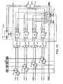
- Fig. 13 is a diagram of the preferred N-channel multi-priority scheduler architecture that includes the mask generator unit 190, mask compare sub-units 192, 194, 196 and 198, the level-specific sub-scheduling units 202, 204, 206 and 208, the priority encoder unit 210, and the resource management unit 230.
- the preferred architecture reflects a scheduler where M, the number of packet priority levels and request buffer registers per channel, is equal to 4.
- a request for example, RQ_CHO_L0 enters a mask compare sub-unit 192 at the request input (RI).
- the level 0 mask enters the mask compare sub-unit at MSK and an input vector, IVEC, enters at INP_BSY.
- the vectors are compared as described above, and a request is output from the request output (RO) to an N:1 multiplexer 212.
- the N:1 multiplexer designates the request as high priority where applicable and forwards the request to a sub-scheduling unit 202 of the level-specific scheduling unit for L0.
- the input vector, IVEC, and an output vector, OVEC are input into the level-specific sub-scheduling unit from the resource management unit along with the request for channel 0 at level 0, RQ_CH0_L0 from the mask compare sub-unit.
- a grant is issued from the level-specific sub-scheduling units 202-208 based on the availability of input channels and output channels and the round-robin priority as described above.
- the updated input and output vectors are sent to respective multiplexers as IVEC_NEXT_L0 and OVEC_NEXT_L0, while the grant is sent to the priority encoder unit as IGRANT_L0.
- the priority encoder unit 210 receives four grants from the four level-specific sub-scheduling units 202-208 for each channel.
- a single grant for a single channel is issued by the priority encoder unit based on packet priority level. That is, the grant with the highest packet priority level is selected among the four available grants and, therefore, if there is a grant for an output channel from level 0, it has priority over all other packet priority levels for the channel.
- the L2 grant is issued and the L3 grant must wait for a later arbitration cycle.
- the preferred channel priority architecture 230 is depicted in Fig. 13 . After being processed through the priority encoder unit, the grant issued based on packet priority level is transmitted to the corresponding channel module accompanied by a level select signal that identifies which packet priority level the request relates to and where in the request buffer the request is located.
- the functions of the overall scheduler unit have been specifically described, it is important to note that the functions may be performed in different orders. For example, it is possible to perform the level-specific sub-scheduling function before the mask compare function. In addition, the process of accounting for input and output channel availability as performed by the resource management unit may differ. Further, the physical boundaries may vary from those described. For example, certain functions such as mask generation may be performed outside the physical boundaries of the scheduler.
- Fig. 14 graphically represents buffered requests from an N-channel multipoint switch.
- the channel modules have the ability to buffer M requests in their respective buffers with a packet priority designation that ranges from a highest packet priority at level 0, L0, to a lowest packet priority at level M, LM.
- packet priority refers to the priority level of one buffered request for a channel versus another buffered request for the same channel.
- Time is used as the packet priority basis in this embodiment and under the time approach L0 contains the oldest request in the buffer and has the highest packet priority.
- Levels 1, 2, and 3 contain sequentially newer requests and have sequentially lower packet priority.
- Round-robin priority refers to the channel that is designated as high round-robin priority under the rotating round-robin channel priority scheme. As described above, once a channel is designated as high round-robin priority, the channel maintains the designation for successive arbitration cycles until a grant is issued for the channel. Round-robin priority after the high priority channel is distributed sequentially in descending order from the high round-robin priority channel.
- CH13 is the highest round-robin priority channel
- CH14 is the next highest round-robin priority
- CH15 is the next highest round-robin priority
- CH0 is the next highest round-robin priority
- the preferred multilevel in-parallel arbitration (MLIPA) process is described with reference to Fig. 15 .
- L0 is designated high packet priority and channel 0 has the highest round-robin priority. Therefore, in the first clock, phase 1, the four requests, L0-L3, for CH0 are arbitrated as described above. Simultaneously, the L0-L3 requests are processed through the mask compare unit, the level-specific scheduling unit, and the priority encoder unit. Out of the parallel process, one request from one of the four packet priority levels will be granted.
- CH0 is the highest priority channel, it is likely that the CH0_L0 request will receive the grant even if it is a multicast request that requires available output channels to be reserved while unavailable output channels become available.
- phase 2 the four requests, L0-L3, for CH1 are arbitrated as described above.
- the arbitration of the four requests is performed in parallel and, if possible, one request is issued for the channel.
- phase 3 the four requests, L0-L3, for CH2 are arbitrated as described above.
- the arbitration continues for sixteen clocks and at the end of sixteen clocks sixty-four requests have been arbitrated and grants have been issued in a manner that maximizes input channel and output channel utilization.
- a complete arbitration cycle requires eighteen clocks, two clocks for arbitration preparation and sixteen clocks for arbitration.
- the sixteen clocks that are required to arbitrate the sixty-four requests are synchronized to the sixteen clocks that are required to transmit the data cell portion of a switching cell, as described with reference to Fig. 6 .
- preparations are made for the next arbitration process.
- In the first clock all of the done signals are reviewed and the channels that have become available during the preceding arbitration cycle are released by clearing the appropriate input vectors and output vectors. Additionally, in the first clock the request buffers are replenished to fill request registers vacated by the requests that were granted in the last arbitration cycle.
- new masks that reflect the newly replenished buffers, are generated for the four packet priority levels and the round-robin priority is rotated if the highest round-robin priority channel received a grant in the last arbitration cycle.
- the requests in the request buffers can be arbitrated one request at a time, one packet priority level at a time, as depicted in Fig. 16 .
- the arbitration process would arbitrate sixty-four requests in sixty-four clocks.
- the arbitration would start at the highest round-robin priority and highest packet priority request, for example, RQ_CH0_L0.
- Phase 1 requires sixteen clocks
- phase 2 requires sixteen clocks
- phase 3 requires sixteen clocks
- phase 4 requires sixteen clocks for a total of sixty-four clocks.
- Grants are issued on a first request-first grant basis with the round-robin priority rotating each arbitration cycle as described above.
- An advantage of this approach is the simplicity found in the fact that mask generation, mask comparing, and parallel arbitration are not being performed.
- a disadvantage is that one arbitration cycle takes sixty-four clocks as opposed to eighteen clocks per cycle for the arbitration method described above.
Abstract
Description
- The invention relates generally to the scheduling of variable-size packets in a high-bandwidth input-buffered multipoint switch, for instance as used in gigabit ethernet network. More particularly, the invention describes a non-blocking scheduler that utilizes a parallel multi-level arbitration method.
- Networks are widely used to transfer voice, video, and data between various network devices such as telephones, televisions, and computers. Data transmitted through a network is typically segmented into packets and under some network protocols data is segmented into fixed-length cells. For example, Asynchronous Transfer Mode (ATM) protocol requires 53-byte cells, with 5 bytes of each cell designated for a header and 48 bytes of each cell designated for payload. Other network protocols, such as ethernet or Internet protocol, carry data in variable-size packets.
- Switches are integral parts of most networks. Switches receive packets from input channels and direct packets to the appropriate output channels of the switch. Typical switches have three components: a physical switch fabric to provide the connections from input channels to output channels, a scheduling mechanism to direct traffic when multiple packets arrive on different input channels destined for the same output channel, and a buffering or queuing mechanism at the switch input or output to accommodate traffic fluctuations without undue packet loss.
Fig. 1 is a diagram of aprior art switch 10 that has fourinput channels output channels serial input queues physical switch 38, and acrossbar scheduler 40. The crossbar scheduler receives a signal, referred to as a request, from an input queue. The request dictates the output channel or channels that will receive the queued packet. The scheduler arbitrates between competing requests and sends a signal, referred to as a grant, back to the input buffers that have been selected to deliver a packet. - In switches such as the
switch 10 described in reference toFig. 1 , each input queue 28-36 provides requests to thescheduler 40 one at a time on a first-in-first-out (FIFO) basis and the scheduler arbitrates among the four requests received from the four input queues, with a goal of maximizing utilization of the input channels 12-18 and output channels 20-26 of the switch. As a grant is issued to a particular input channel to access a target output channel or channels, a new request is accessible by the scheduler in place of the granted request. - A problem known as head-of-line (HOL) blocking is created when one of the requests at the head of a queue line is a request for an output channel that is not available. HOL blocking is common when a multicast request is made because there is a lower probability that all of the output channels for the multicast request will be available immediately. When a request from a particular input channel is forced to wait until all output channels are available, all of the packets associated with the particular input channel are also forced to wait, thereby slowing the transfer of data from that input channel.
- As one remedy to solving HOL blocking problems, parallel input queues have been implemented. Parallel input queues provide a separate FIFO queue for each output channel of the switch, with each queue providing a corresponding request to the scheduler. Referring to
Fig. 2 , an N input channel by N output channel switch requiresN input queues 46 for each input channel for a total of N2 input queues. With an N2 scaling factor, the number of input queues connected to thecrossbar scheduler 50 may be very high. For example, in a 16×16 switch, 256 separate queues are required. In spite of the added complexity, the advantage that the parallel design provides is that, with respect to any one of the input channels, a series of requests for available output channels is not held up by a single request for in-use output channels. - A variety of arbitration techniques can be used with parallel input channels to provide an efficient throughput through a switch. For example, maximum matching algorithms are designed in an attempt to assign output channels to input channels in such a way that a maximum number of transfers occur simultaneously. However, under heavy load conditions, maximum matching algorithms can prevent some requests from being granted, creating a new blocking problem. For example, referring to
Fig. 3 ,input channel 1 is represented as requesting to transfer cells from its output-distributedqueue 54 tooutput channel 1 only, whileinput channel 2 is requesting to transfer cells from its output-distributedqueue 56 tooutput channels input channel 1 transmits cells to outputchannel 1 andinput channel 2 transmits cells to outputchannel 2. However,input channel 2 will be blocked from transferring cells destined foroutput channel 1, since this would require the cell transfer frominput channel 1 to outputchannel 1 to stop, and as a result, onlyoutput channel 1 would be utilized. As shown inFig. 4 , sending cells frominput channel 2 tooutput channel 1 causesinput channel 1 andoutput channel 2 to remain idle and does not achieve maximum matching. - Arbitration methods developed to optimize performance of high speed switches utilizing parallel input queues are disclosed in
U.S. Pat. No. 5,500,858 , entitled "Method and Apparatus for Switching Cells in an Input-Queued Switch," issued to McKeown and inU.S. Pat. No. 5,517,495 , entitled "Fair Prioritized Scheduling in an Input-Buffered Switch," issued to Lund et al. Although these arbitration approaches are effective for their intended purpose, they both require that an NxN switch have N2 distinct FIFO input queues. Since there are N2 distinct FIFO input queues, there will also be N2 requests delivered to the scheduler. As the number of input and output channels increases, the complexity of providing N2 input queues and sending N2 requests to the scheduler becomes costly and difficult to implement. - In addition to the problem of added complexity, the output-distributed queue architecture does not easily support multicast requests, which are more common in network protocols such as ethernet than in network protocols such as ATM. For example, in order to utilize the output-distributed architecture of
Fig. 2 to satisfy a multicast request, the cell that is to be multicasted must either be replicated into all of the output channel queues that are indicated by the request or a separate multicast queue must be established in addition to the N2 queues already present. - The document, Ruixue Fan; Suzuki H; Yamada K; Matuura N; Expandable ATOM switch architecture (XATOM) for ATM LANs; Communications, 1994. ICC '94, SUPERCOMM/ICC '94, IEEE International Conference on New Orleans, LA, USA 1 - 5 May 1994; 1994-05-01; PG 402 - 409; XP010126771), discloses an expandable switch architecture for ATM LANs. The document,
EP-A-0 771 132 , discloses a multiplexer in an ATM switch that includes input and output buffers and a device to control the internal flows of ATM cells. The document,WO 97/04564 EP-A-0 603 916 , discloses an ATM switch system that includes input buffers and output buffers and a self-routing network for routing packets from the input buffers to the output buffers. - As a result of the shortcomings of conventional output-distributed queue architecture, what is needed is a method and apparatus that limit the number of input queues and the complexity of sending requests to a scheduler, while still maintaining fair and efficient scheduling.
- A method and apparatus according to the present invention are set out in the independent claims, to which the reader is now referred. Preferred features are laid out in the dependent claims.
- A method and apparatus for scheduling variable-size data packets in a multipoint switch utilize request buffers having multi-level request registers that are linked in parallel to a scheduler to allow arbitration among requests of different input channels and different priority levels. Arbitration among the totality of requests can be executed on a priority basis such that grants are issued in response to requests in a sequence from the lowest priority request to the highest priority request. Alternatively, arbitration among different priority requests from the same input channel can be performed simultaneously in parallel on a channel-by-channel basis.
- The preferred multipoint switch has N input channels and N output channels (e.g., N = 16), with each input channel having a request buffer with M request registers (e.g., M = 4) of different priorities for storing up to M requests with packet priority levels that correspond to the priorities of the request registers. The N request buffers are connected to a data path multiplexer and a scheduler. The NxM request registers of the N request buffers are connected in parallel to the scheduler, such that the scheduler can simultaneously access all N×M requests.
- The scheduler of the preferred embodiment switches variable-size data packets by utilizing the requests from the request buffers to manage data traffic through the data path multiplexer in a manner that is designed to maximize the throughput of data without unfairly delaying lower priority data. To accomplish fair and efficient scheduling of variable-size data packets, the scheduler includes a mask generator unit, a mask compare unit, a level-specific scheduling unit, a priority encoder unit, and a resource management unit. The mask generator unit is a circuit that generates priority level-specific masks that are utilized in the arbitration process to indicate which output channels will be utilized by the input channels for a specific packet priority level. In the preferred 16×16 switch, a level-specific mask consists of a 16-bit vector where each bit represents one of the output channels. A level-specific mask is generated by combining all of the request vectors from the
request channels 0 through 15 for the same packet priority level to form a single mask vector that represents all of the requests. - The mask compare unit is a circuit that compares level-specific masks generated by the mask generator to the availability of the input channels and to the requests from the corresponding packet priority level. The mask compare unit looks for conflicts between available inputs, requested outputs, and the corresponding mask.
- The level-specific scheduling unit is a circuit that contains a level-specific sub-scheduler for each packet priority level. In the 16×16 switch, there are four level-specific sub-schedulers corresponding to the four packet priority levels. The level-specific sub-schedulers receive level-specific requests that are output from the mask compare unit and compare the input and output vectors, the requesting channel, and the requests to determine if channel conflicts exist. If no channel conflict exists between the input vector, the output vector, the requesting channel, and the request vector, a grant is issued and the input and output vectors are set to reflect a new grant.
- The level-specific sub-scheduling units utilize a round-robin arbitration scheme to guarantee fairness among input channels. Under this scheme, initially,
channel 0 is designated as having the highest round-robin channel priority (hereinafter round-robin priority) andchannel 15 is designated as having the lowest round-robin priority. Note that round-robin priority is relevant to the channel order inside the level-specific sub-schedulers and different from the packet priority, which is relevant to the order in which requests are presented from channel modules. Inside the level-specific sub-schedulers, requests are processed between channels in round-robin priority order such that requests from channels with higher round-robin priority are granted access to output channels whenever there is contention with requests from channels with lower round-robin priority. Once the channel with the highest round-robin priority receives a grant, the highest round-robin priority designation is rotated to the next input channel with a pending request. Under this rotating round-robin channel priority approach, every channel will periodically be designated as the highest priority. - High round-robin priority designation plays an especially important role in allowing multicast transmissions through a switch. Multicast requests are difficult to schedule in high-traffic environments, because the likelihood that all output channels are available is low. To guarantee bounded latency for multicast and broadcast traffic, when a channel is designated as the highest round-robin priority, any output channels requested by the channel will be reserved by the scheduler, unless the output channels are required by requests from other channels with higher packet priority until all of the output channels required to grant this request become available.
- The priority encoder unit is responsible for implementing the packet priority order and issuing the final grants to the channel modules. When there are one or more possible grants transmitted to the priority encoder unit from the four level-specific sub-schedulers in the current scheduling cycle, the priority encoder unit picks the grant corresponding to the request with the highest packet priority and passes the grant on to the requesting channel module. The priority encoder unit also sends the updated values of the input and output channel utilization to the resource management unit.
- The resource management unit is responsible for maintaining the status of the input and output channels. Every time a grant is issued, the input channel that received the grant and the output channels that are going to be used in the packet transfer are marked as busy. When the end of a packet transfer is signaled by the channel module using a done signal, the input channel and the output channel used in the transfer are cleared so that the cleared channels can be scheduled for another transfer.
- An advantage of the invention is that the sixteen request buffers with four request registers per buffer utilized in a 16×16 switch are significantly less complex than the 256 queues required for a 16×16 switch using a conventional output-distributed scheduling architecture. In addition, the invention readily allows multicast requests to be granted and the corresponding cells to be transmitted from the input buffers to the output channels. Further, the multi-level request buffers eliminate the HOL blocking problem, because the scheduler has simultaneous and in-parallel access to more than one request for each input channel. The invention also allows for packet-by-packet scheduling of variable-size packets, which eliminates the reassembly overhead associated with cell-based switching systems.
- In addition, the invention allows multicast requests to be processed efficiently such that multicast packets are transferred from the source input port to all target output ports simultaneously and multiple multicast transfers can be concurrently scheduled from multiple input ports to multiple sets of output ports.
-
-
Fig. 1 is a diagram of a prior art switch that has four input channels and four output channels. -
Fig. 2 is an N input channel by N output channel switch with N2 output-distributed input queues. -
Fig. 3 is a depiction of the transferring of cells from output-distributed input queues to output channels where maximum matching between input and output channels is achieved using prior art techniques. -
Fig. 4 is a depiction of the transferring of cells from output-distributed input queues to output channels where maximum matching between input and output channels is not achieved using the prior art techniques. -
Fig. 5 is a diagram of the switch fabric architecture in accordance with the present invention. -
Fig. 6 is a diagram of a data packet and an expanded switching cell that is transmitted through the switch fabric ofFig. 5 . -
Fig. 7 is an expanded diagram of a channel module as shown inFig. 5 . -
Fig. 8 is an expanded diagram of the scheduler as shown inFig. 5 . -
Fig. 9 is an example matrix of requests fromswitch input channels 0 through 3 atpacket priority levels 0 through 3. -
Fig. 10A is an example of thelevel 1 mask generation for the requests atlevel 1 inFig. 9 . -
Fig. 10B is an example of thelevel 2 mask generation for the requests atlevel 2 inFig. 9 . -
Fig. 10C is an example of thelevel 3 mask generation for the requests atlevel 3 inFig. 9 . -
Fig. 11A is an example of the mask compare process for a request shown inFig. 9 . -
Fig. 11B is an example of the mask compare process for a request shown inFig. 9 . -
Fig. 12 is an example of the level-specific sub-scheduling process for the requests related toFigs. 9 and11B . -
Fig. 13 is a diagram of the preferred N-channel multi-priority scheduler architecture for the scheduler shown inFigs. 5 and6 . -
Fig. 14 is a depiction of the preferred multi-level in-parallel arbitration process for an N×N switch with M packet priority levels in accordance with the invention. -
Fig. 15 is a depiction of the preferred multi-level in-parallel arbitration process for a 16×16 switch with four packet priority levels in accordance with the invention. -
Fig. 16 is a diagram of an alternative single level, single channel arbitration process for an N×N switch with M packet priority levels in accordance with the invention. -
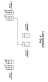
Fig. 5 is a diagram of a preferred embodiment of the invention. For diagram purposes a 4x4 version of an N×N multipointswitch fabric 60 is depicted, although a 16×16 switch is preferred. In the preferred embodiment, theinput channels output channels packet processing units - Referring to
Fig. 6 , each 36-byte switching cell 140 consists of a 4-byte command cell 142 and a 32-byte data cell 144. Using 16-bit channels, each switching cell is sent through the switch over eighteen clocks and a framingpulse 146 is used to indicate the termination of one switching cell and the beginning of an adjacent switching cell. Each command cell consists of two command fields. The first command field contains a request or response that is used to exchange messages related to switching arbitration. The second command field contains a data identifier that carries information relating to the data cell in the current switching cell. The data cell carries the data that is a part of alarger packet 150 from which the switching cell was segmented. After the switching cells pass through the data path multiplexer, the data cell portions of the switching cells are reassembled into variable-length packets by the OPPs for transmission within the network. - Referring back to
Fig. 5 , switching cells are transmitted between the IPPs/OPPs 92-98 and 102-108 and the correspondingchannel modules -
Fig. 7 is an expanded diagram of an examplechannel module N 118. The channel module ofFig. 7 has arequest buffer 128 that can store M requests 160, 162, 164, 166 in M request registers and that can provide M requests to a scheduler in parallel. In the preferred 16×16 switch, M is equal to 4. That is, there can be up to four requests stored in each of sixteen request buffers for a total of sixty-four requests. With one buffer per channel and four request registers per buffer, a 16×16 switch has only sixteen buffers and provides only sixty-four requests to a scheduler per arbitration cycle, in comparison to a conventional 16×16 switch with output-distributed queues which would require N2, or 256, request buffers and would provide N2, or 256, requests to a scheduler per arbitration cycle. - The request buffers 122-128 of
Fig. 5 and7 are filled from the IPPs 92-98 in different manners, depending on what packet priority scheme is being implemented in the switch. If the packet priority scheme is based upon time, where the oldest request has the highest packet priority, then the buffer is filled on a FIFO basis. InFig. 7 , therequest buffer 128 for channel N has fourrequest register designations vacant request register 166 is then available to receive a new request from theIPP 98. - On the other hand, the packet priority scheme may be based upon a factor other than time. For example, the packet priority scheme may be based upon the source of the data or the type of data. Under such a packet priority scheme, the four registers 160-166 in the
request buffer 128 can be identified, for example, as control, high, medium, and low priority, with control being the highest packet priority (i.e., L0) and low being the lowest packet priority (i.e., LM). When a request is granted under this scheme, the vacant request register is resupplied with a request having the same packet priority level as the request for which a grant was just issued. -
Fig. 7 also depicts the specific input and output links associated with each channel module, using channel N as an example. The data_in and data_out links located at the top of thechannel module 118 are used to transport command cells, data cells, grants and level selects between the channel module and the IPP/OPP. The input grant link (IGRANT_CHN) and level select link (LEVEL_SEL) located at the right side of the channel module are used to transport the IGRANT_CHN signal and LEVEL_SEL signal from the scheduler to the channel module. The IGRANT_CHN signal represents an input grant that has been issued by the scheduler for channel N. The LEVEL_SEL signal represents the packet priority level that corresponds to the IGRANT_CHN signal. For example, the LEVEL_SEL signal will identify one of the levels L0 through LM corresponding to a CHN grant. - The channel N request links
level 0 through level M (RQ_CHN_L0 through RQ_CHN_LM) and the done link (DONE_CHN) located at the bottom right of thechannel module 118 are used to transport the channel requests and a done signal to the scheduler. The M request links are routed to the scheduler in parallel and provide the M requests to the scheduler simultaneously. As will be discussed further, providing parallel delivery of M requests helps to minimize the HOL blocking problem discussed above. The request links in the preferred 16×16 switch are 16-bit channels that carry requests that include a 16-bit crossbar exit channel descriptor (CEP). The 16-bit CEP has one bit associated with each output channel, and the desired output channels are identified by setting the bits that correspond to the output channels. - The DONE_CHN signal indicates to the scheduler when the input channel has completed transmitting the current group of switching cells. Switching cells that are segmented from the same packet are ideally transmitted one after another. Since packets are variable length and are therefore made up of a variable number of switching cells, it is preferred that the scheduler be informed when an input channel has completed transferring of a group of switching cells. The DONE_CHN signal is also used to determine which output channels have become available to receive switching cells. Determining available output channels from a DONE_CHN signal that indicates the availability of an input channel is accomplished through a look-up table. A look-up table is updated each time a grant is issued to an input channel. The look-up table identifies which output channels will be utilized by the input channel for the granted cell transfer. When a DONE_CHN signal is received by the scheduler, the look-up table for the corresponding input channel is accessed and the identified output channels in the look-up table are released and made available for future switching.
- The data to and from the multiplexer links (data_to_mux and data_from_mux) and the multiplexer setup link (mux_set) located at the bottom left of the
channel module 118 are used to transfer data cells to and from the multiplexer and to set up the data paths within the multiplexer for the transfer of switching cells. - Although not represented, the
channel module 118 also performs a time-out function to limit the amount of time and therefore the number of cells that can be transferred uninterrupted by a single input/output channel combination. Every time a grant is issued to an input channel, a timeout counter in the corresponding channel module is set to the timeout value. During every successive clock cycle, the timeout counter is decremented and if the input channel cannot complete the transfer within the timeout period, the timeout counter expires and the transfer is terminated. - In the preferred embodiment, the timeout counters in the channel modules are set to allow up to 4,096-byte packets to be switched in one uninterrupted event.
- Referring back to
Fig. 5 , the channel modules 112-118 are connected to a data path multiplexer 130 that provides the physical paths for data cell switching between channels. The preferred data path multiplexer has the ability to unicast data cells and to multicast data cells. In the preferred embodiment, the data path multiplexer is a multipoint switch, although in another embodiment the data path multiplexer can be a crossbar switch. The type of data path multiplexer is not critical to the invention. - The channel modules 112-118 are also connected to a
scheduler 132. The scheduler utilizes the requests from the channel modules to manage the cell traffic through the data path multiplexer in a manner that maximizes the throughput of switching cells without unfairly delaying lower priority data. -
Fig. 8 is an expanded view of thescheduler 132. The scheduler is first described in terms of the input and output links and then in terms of the functional blocks within the scheduler that operate to generate the output signals. Located along the top of the scheduler, request links and done signal links are connected to the scheduler for receiving requests and done signals from the channel modules as depicted inFig. 7 . Each channel has M parallel request links between the channel modules and the scheduler and in the preferred embodiment there are four parallel request links per channel. The highest packet priority request link is identified as, for example, RQ_CH0_L0, where "RQ" is short for request, "CH0" is short forchannel 0, and "L0" is short forpacket priority level 0. As described above, each request link consists of 16-bit channels where a 16-bit field is delivered to the scheduler in a single clock. The DONE_CH0 signal is received from the channel module and indicates when an input is available and what corresponding outputs are available. - The output links located along the right side of the scheduler include a grant link for each channel and a level select link. As described with reference to the channel modules, the grant links transmit the IGRANT_CHN signals generated within the scheduler to the channel modules to indicate that a request from a particular channel has been granted. The LEVEL_SEL link transmits a LEVEL_SEL signal to the channel module along with each grant to indicate the packet priority level of the granted request. For example, if a request is granted to channel N, the LEVEL_SEL signal indicates to channel module N the particular packet priority level of the request.
- The functional blocks within the scheduler depicted in
Fig. 8 include amask generator unit 170, a mask compareunit 172, a level-specific scheduling unit 174, apriority encoder unit 176, and aresource management unit 178. The mask generator unit is a circuit that generates packet priority level-specific masks that are utilized in the arbitration process to indicate which output channels will be utilized by the input channels for a specific packet priority level. In the preferred 16×16 switch, a level-specific mask consists of a 16-bit vector where each bit is dedicated to one of the output channels. A level-specific mask is generated by combining all of the request vectors from the request channels 0-15 for the same packet priority level to form a single mask vector that represents all of the requests. - In an example related to the N×N switch of
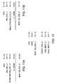
Fig. 5 , masks are generated from the requests of input channels 0-3, CHO-CH3, havingpacket priority levels 1 through 3, L1-L3. The channels 0-3 are the input channels 62-68, respectively. For example purposes,Fig. 9 represents the requests from channels CHO-CH3 at packet priority levels L0-L3.Figs. 10A-10C represent the mask generation for the L1_MASK, the L2_MASK and the L3_MASK. The L1_MASK is generated from the aggregate of the requests for channels CH0 through CH3 at packet priority level L0. The mask, represented inFig. 10A as L1_MASK, has a bit set to "1" at any place where an L0 request for any channel was set to "1." The end result is that the mask represents all outputs that are requested by the stored requests that are designated as having the highest packet priority levels. As depicted inFigs. 10B and 10C , the L2 and L3 masks are generated by building on the lower level masks in the same manner. The highest packet priority level mask, L0_MASK (not shown), is generated by simply copying the highest packet priority request that is related to the channel with the highest round-robin priority designation. Round-robin priority refers to a priority scheme among channels that is used in the arbitration process and will be discussed further below. Preferably, all of the masks are regenerated once before each eighteen clock arbitration cycle, but the masks can be regenerated every clock, if desired. The algorithms for creating four masks for an N×N switch are as follows: - L0_MASK = RQ_CHX_L0, where CHX is the channel with the "high priority" designation
- L1_MASK = (RQ_CH0_L0) | (RQ_CH1_L0)| ... (RQ_CHN_L0)
- L2_MASK = L1_MASK | (RQ_CH0_L1) | (RQ_CH1_L1) | ... (RQ_CHN_L1)
- L3_MASK = L2_MASK | (RQ_CHO_L2) | (RQ_CH1_L2) | ... (RQ_CHN_L2)
- The next functional block in
Fig. 8 is the mask compareunit 172. The mask compare unit is a circuit that compares level-specific masks to the availability of the input channels and to the requests from the corresponding priority level, while monitoring for conflicts between available inputs, requested outputs, and the mask. The availability of inputs is represented by an input vector (IVEC) that is an N bit vector where N equals the number of input channels in the switch. In the 4×4 switch example, the IVEC is a 4-bit vector with unavailable input channels having a corresponding bit set to "1." Referring toFigs. 11A and 11B , examples of the mask compare process are depicted. In the example ofFig. 11A , the request used, RQ_CH1_L1, is taken fromFig. 9 and includes the 4-bit request vector "0010." The input vector, IVEC, is exemplary and is the 4-bit vector "0100," representing thatinput channel 1 is unavailable or busy. Since the unavailable input channel is the same as the input channel making the request, the request cannot be granted to the busy channel and all request bits are set to "0." The resulting request is compared to the L1_MASK, which represents the higher priority output channel requests from L0. Since the resulting RQ_CH1_L1 is the 4-bit vector "0000," a request for zero output channels is passed on to the level-specific scheduling unit. - In the example of
Fig. 11B , request RQ_CH2_L1 is taken fromFig. 9 and is the 4-bit request vector "0010." The input vector is exemplary and is the same 4-bit vector "0100" as used in the previous example. Since the input vector indicates thatonly input channel 1 is unavailable and the request is frominput channel 2, the resulting request vector remains "0010." The L1_MASK vector is again "1001" which represents thatoutput channels - Referring back to
Fig. 8 , the next functional block is the level-specific scheduling unit 174. The level-specific scheduling unit is a circuit that contains a level-specific sub-scheduler for each packet priority level. In the preferred embodiment of the 16×16 switch, there are four packet priority levels and therefore four level-specific sub-schedulers. The level-specific sub-schedulers receive the level-specific requests that are output from the mask compareunit 172 and compare input and output vectors to the requesting channel and to the request vector to determine if channel conflicts exist. If no channel conflicts exist between the input vector, output vector, requesting channel, and request vector, a grant is issued and the input and output vectors are set to reflect the new grant. - The level-specific sub-scheduling units utilize a round-robin arbitration scheme to guarantee fairness among requests of the same priority level. Under the round-robin scheme, initially,
channel 0 is designated as having the highest round-robin channel priority andchannel 15 is designated as having the lowest round-robin priority. Note that round-robin priority is relevant to the channel priority order inside the level-specific sub-schedulers and is different from the packet priority, which is relevant to the order in which requests are presented from channel modules. Inside the level-specific sub-schedulers, requests are processed between channels in round-robin priority order such that requests from channels with higher round-robin priority are granted access to output channels whenever there is contention with requests from channels with lower round-robin priority. Once the channel with the highest round-robin priority receives a grant, the highest round-robin priority designation is rotated to the next input channel with a pending request. Under the rotating round-robin channel priority approach, every channel will periodically be designated as the highest priority. - High round-robin priority designation plays an especially important role in allowing multicast transmissions through a switch. Multicast requests are difficult to schedule in high-traffic environments, because the likelihood that all output channels are available is low. To guarantee bounded latency for multicast and broadcast traffic, when a channel is designated as the highest round-robin priority, any output channels requested by the channel will be reserved by the scheduler, unless the output channels are required by requests from other channels with higher packet priority until all of the output channels required to grant the request become available.
- An example of the level-specific sub-scheduling process is depicted in
Fig. 12 for one packet priority level. For the example, assume thatchannel 2 has the highest round-robin priority. The example is a continuation of the example ofFig. 11B . InFig. 12 , the input vector is still "0100," the exemplary output vector is "0001," and the request RQ_CH2_L1_ is "0010." The input vector indicates thatinput channel 1 is busy and the output vector indicates thatoutput channel 3 is busy. The request RQ_CH2_L1 is forinput channel 2 to transmit a cell tooutput channel 2, neither of which conflicts with the input vector or output vector. Since no conflicts exist between the request, the requesting channel, the input vector, and the output vector, a grant with vector "0010" is issued for CH2_L1. Along with the grant, the level-specific sub-scheduling unit also generates updated input and output vectors that represent the IVEC and the OVEC that will be utilized if the request is granted. The updated input vector and output vector are identified as IVEC_NEXT_L1 and OVEC_NEXT_L1. In the example, IVEC will change from "0100" to "0110" to signify thatinput channel 2 will also be busy and OVEC will change from "0001" to "0011" to indicate thatoutput channel 2 will also be busy. - Referring back to
Fig. 8 , the next functional block is thepriority encoder unit 176. The priority encoder unit is a circuit that is responsible for implementing the packet priority order and issuing the final grants to the channel modules. When there are one or more possible grants transmitted to the priority encoder unit from the four level-specific sub-schedulers in the current scheduling cycle, the priority encoder unit picks the grant corresponding to the request with the highest packet priority and passes the grant on to the requesting channel module. The priority encoder unit also sends the updated values of the input and output channel utilization to the resource management unit to update IVEC and OVEC. - Referring back to
Fig. 8 , theresource management unit 178 is responsible for maintaining the status of the input and output vectors IVEC and OVEC, respectively. Every time a grant is issued, the input vector bit related to the input channel that received the grant and the output vector bit related to the output channels that are going to be used in the packet transfer are marked as busy. When the end of a packet transfer is signaled by the channel module using a done signal, the respective input vector bits and output vector bits marked during the transfer are cleared so that the channels can be scheduled for another transfer. -
Fig. 13 is a diagram of the preferred N-channel multi-priority scheduler architecture that includes themask generator unit 190, mask compare sub-units 192, 194, 196 and 198, the level-specificsub-scheduling units priority encoder unit 210, and theresource management unit 230. The preferred architecture reflects a scheduler where M, the number of packet priority levels and request buffer registers per channel, is equal to 4. Following a logical flow, a request, for example, RQ_CHO_L0 enters a mask compare sub-unit 192 at the request input (RI). Thelevel 0 mask enters the mask compare sub-unit at MSK and an input vector, IVEC, enters at INP_BSY. The vectors are compared as described above, and a request is output from the request output (RO) to an N:1multiplexer 212. The N:1 multiplexer designates the request as high priority where applicable and forwards the request to asub-scheduling unit 202 of the level-specific scheduling unit for L0. The input vector, IVEC, and an output vector, OVEC, are input into the level-specific sub-scheduling unit from the resource management unit along with the request forchannel 0 atlevel 0, RQ_CH0_L0 from the mask compare sub-unit. - A grant is issued from the level-specific sub-scheduling units 202-208 based on the availability of input channels and output channels and the round-robin priority as described above. The updated input and output vectors are sent to respective multiplexers as IVEC_NEXT_L0 and OVEC_NEXT_L0, while the grant is sent to the priority encoder unit as IGRANT_L0.
- The
priority encoder unit 210 receives four grants from the four level-specific sub-scheduling units 202-208 for each channel. A single grant for a single channel is issued by the priority encoder unit based on packet priority level. That is, the grant with the highest packet priority level is selected among the four available grants and, therefore, if there is a grant for an output channel fromlevel 0, it has priority over all other packet priority levels for the channel. Similarly, if there are no grants for packet priority levels L0 and L1, but there are grants for packet priority levels L2 and L3, then the L2 grant is issued and the L3 grant must wait for a later arbitration cycle. - If a grant is issued to the high priority channel, then the high priority designation is shifted to the next channel. The preferred
channel priority architecture 230 is depicted inFig. 13 . After being processed through the priority encoder unit, the grant issued based on packet priority level is transmitted to the corresponding channel module accompanied by a level select signal that identifies which packet priority level the request relates to and where in the request buffer the request is located. - Although the functions of the overall scheduler unit have been specifically described, it is important to note that the functions may be performed in different orders. For example, it is possible to perform the level-specific sub-scheduling function before the mask compare function.
In addition, the process of accounting for input and output channel availability as performed by the resource management unit may differ. Further, the physical boundaries may vary from those described. For example, certain functions such as mask generation may be performed outside the physical boundaries of the scheduler. - The preferred arbitration method is further explained with reference to
Fig. 14 , which graphically represents buffered requests from an N-channel multipoint switch. The channel modules have the ability to buffer M requests in their respective buffers with a packet priority designation that ranges from a highest packet priority atlevel 0, L0, to a lowest packet priority at level M, LM. In the preferred embodiment, N is 16, indicating sixteen channels CH0-CH15 and M is 4, indicating four request storage registers and four corresponding packet priority levels L0-L3 related to each channel for a total of 4×16 = 64 request buffer registers. - In the preferred arbitration method, packet priority refers to the priority level of one buffered request for a channel versus another buffered request for the same channel. Time is used as the packet priority basis in this embodiment and under the time approach L0 contains the oldest request in the buffer and has the highest packet priority.
Levels - With the priority protocol established, the preferred multilevel in-parallel arbitration (MLIPA) process is described with reference to
Fig. 15 . In the example, it is assumed that L0 is designated high packet priority andchannel 0 has the highest round-robin priority. Therefore, in the first clock,phase 1, the four requests, L0-L3, for CH0 are arbitrated as described above. Simultaneously, the L0-L3 requests are processed through the mask compare unit, the level-specific scheduling unit, and the priority encoder unit. Out of the parallel process, one request from one of the four packet priority levels will be granted. Remembering that CH0 is the highest priority channel, it is likely that the CH0_L0 request will receive the grant even if it is a multicast request that requires available output channels to be reserved while unavailable output channels become available. - In the next clock,
phase 2, the four requests, L0-L3, for CH1 are arbitrated as described above. The arbitration of the four requests is performed in parallel and, if possible, one request is issued for the channel. In the next clock,phase 3, the four requests, L0-L3, for CH2 are arbitrated as described above. As can be seen, the arbitration continues for sixteen clocks and at the end of sixteen clocks sixty-four requests have been arbitrated and grants have been issued in a manner that maximizes input channel and output channel utilization. - A complete arbitration cycle requires eighteen clocks, two clocks for arbitration preparation and sixteen clocks for arbitration. The sixteen clocks that are required to arbitrate the sixty-four requests are synchronized to the sixteen clocks that are required to transmit the data cell portion of a switching cell, as described with reference to
Fig. 6 . Before a new sixteen clock arbitration process begins, and during the two clocks required to transmit the command cell portion of the next switching cell, preparations are made for the next arbitration process. In the first clock, all of the done signals are reviewed and the channels that have become available during the preceding arbitration cycle are released by clearing the appropriate input vectors and output vectors. Additionally, in the first clock the request buffers are replenished to fill request registers vacated by the requests that were granted in the last arbitration cycle. In the second and last clock before the next arbitration begins, new masks, that reflect the newly replenished buffers, are generated for the four packet priority levels and the round-robin priority is rotated if the highest round-robin priority channel received a grant in the last arbitration cycle. - In an alternative arbitration method, the requests in the request buffers can be arbitrated one request at a time, one packet priority level at a time, as depicted in
Fig. 16 . In the preferred embodiment where N = 16 and M = 4, the arbitration process would arbitrate sixty-four requests in sixty-four clocks. The arbitration would start at the highest round-robin priority and highest packet priority request, for example, RQ_CH0_L0.Phase 1 requires sixteen clocks,phase 2 requires sixteen clocks,phase 3 requires sixteen clocks, andphase 4 requires sixteen clocks for a total of sixty-four clocks. Grants are issued on a first request-first grant basis with the round-robin priority rotating each arbitration cycle as described above. An advantage of this approach is the simplicity found in the fact that mask generation, mask comparing, and parallel arbitration are not being performed. A disadvantage is that one arbitration cycle takes sixty-four clocks as opposed to eighteen clocks per cycle for the arbitration method described above.
Claims (14)
- An apparatus for scheduling variable-size packets in an input-buffered multipoint switch comprising a plurality of input channels (62, 64, 66, and 68) and a plurality of output channels (72, 74, 76, and 78), the apparatus characterized in that it comprises:multi-level request buffers (122, 124, 126, and 128), each multi-level request buffer being specific to one of said plurality of input channels, said multi-level request buffers having discrete levels for storing requests having different packet priorities, wherein said requests correspond to variable-size packets;a scheduler circuit (132), connected to said multi-level request buffers, to
indicate a transmission status for each of said input and output channels, said transmission status being indicative of channel availability,
arbitrate among a totality of said requests stored in all of said levels of said plurality of multi-level request buffers at least partially based upon a combination of said packet priorities and said transmission statuses of said input and output channels, and
issue grants to said requests in a sequence based upon
said arbitrating among said totality of requests; and
parallel links between each level of said multi-level request buffers and said scheduler circuit, said scheduler circuit being enabled to simultaneously access all of said levels of each said request buffer. - The apparatus of claim 1 wherein said scheduler circuit further includes a mask generator circuit (170) operationally connected to said multi-level request buffers to generate output vectors that are indicative of each output channel that is requested at each of said different packet priorities, each said output vector being associated with one of said packet priorities.
- The apparatus of claim 2 wherein said scheduler circuit further includes a mask comparator circuit (172) operationally connected to said mask generator circuit and said multi-level request buffers to compare each particular output vector to associated requests having a packet priority associated with said each particular output vector, said mask comparator circuit having a plurality of outputs, each output being responsive to said comparing of said each particular output vector to said associated requests and being indicative of availability of output channels represented by said associated requests.
- The apparatus of claim 3 wherein said scheduler circuit further includes a plurality of sula-scheduler circuits (174; 202, 204, 206, 208), each sub-scheduler circuit being operationally connected to an associated output of said mask comparator circuit to generate a level-specific grant for a request having an available input channel and available requested output channels.
- The apparatus of claim 4 wherein said scheduler circuit further includes a priority encoder circuit (176) operationally connected to said sub-scheduler circuits to select a highest priority grant from all grants generated from said sub-scheduler circuits for a specific channel and to transmit said selected highest priority grant to an input channel that corresponds to said selected highest priority request.
- The apparatus of claim 1 further including a data path multiplexer (130) operationally connected between said plurality of input channels and said plurality of output channels, said data path multiplexer having data paths for transmitting variable-size packets to requested output channels when a request specific to an awaiting variable-size packet has been issued a grant by said scheduler circuit.
- The apparatus of claim 1 wherein the transmission status for each of said input and output channels is indicated by channel-specific done signals (DONE_CHN) that indicate the end of a variable-size packet transfer.
- A method for scheduling transmissions of variable-size packets across an input-buffered network switch that connects a plurality of input channels (62, 64, 66, and 68) to a plurality of output channels (72, 74, 76, and 78), each variable-size packet being associated with one of said plurality of input channels, characterized in that said method includes the steps of:storing a first plurality of requests in a first multi-level request buffer (122) that buffers requests related to a first input channel, each said request corresponding to one of said variable-size packets and having a priority;storing a second plurality of requests in a second multi-level request buffer that buffers requests related to a second input channel, each said request corresponding to one of said variable-size packets and having a priority;accessing said first and second pluralities of requests in parallel such that all requests are accessed in parallel;arbitrating among said requests of said accessed first and second pluralities of requests based upon availability of said first and second input channels and availability of requested output channels;issuing a grant in response to that request of said first and second pluralities of requests that has a highest priority and for which respective input channels and output channels are available; andissuing grants in response to those requests of said first and second pluralities of requests that have lower priorities than said highest priority and that utilize input channels and output channels that are not utilized by said request having said highest priority.
- The method of claim 8 further including a step of receiving done signals (DONE_CHN) that indicate when input channels and output channels are available for new variable-size packet transmissions.
- The method of claim 8 wherein said step of arbitrating includes a step of arbitrating requests one at a time in descending priority from highest priority to lowest priority.
- The method of claim 8 wherein said step of arbitrating includes a sub-step of arbitrating requests of all priority levels stored in a request buffer associated with a particular input channel in parallel.
- The method of claim 11 wherein said step of arbitrating requests of all priority levels in parallel includes a step of executing said arbitrations in a fixed sequence with respect to said input channels.
- The method of claim 11 wherein said step of arbitrating requests of all priority levels includes sub-steps of:generating masks (LN_MASK) that represent all requests of similar priority levels; andcomparing a mask for a particular priority level to a request having a same priority level to determine availability of output channels required by said request.
- The method of claim 11 further including the steps of:identifying an input channel having a highest round-robin priority among said plurality of input channels for arbitration purposes; andreserving requested output channels for a multicast request when said multicast request is associated with an input channel that has said highest round-robin priority among said plurality of input channels.
Applications Claiming Priority (3)
| Application Number | Priority Date | Filing Date | Title |
|---|---|---|---|
| US37218 | 1998-03-10 | ||
| US09/037,218 US6044061A (en) | 1998-03-10 | 1998-03-10 | Method and apparatus for fair and efficient scheduling of variable-size data packets in an input-buffered multipoint switch |
| PCT/US1999/004626 WO1999046903A1 (en) | 1998-03-10 | 1999-03-03 | Fair and efficient cell scheduling in input-buffered multipoint switch |
Publications (3)
| Publication Number | Publication Date |
|---|---|
| EP0981878A1 EP0981878A1 (en) | 2000-03-01 |
| EP0981878A4 EP0981878A4 (en) | 2009-07-29 |
| EP0981878B1 true EP0981878B1 (en) | 2011-10-19 |
Family
ID=21893115
Family Applications (1)
| Application Number | Title | Priority Date | Filing Date |
|---|---|---|---|
| EP99911067A Expired - Lifetime EP0981878B1 (en) | 1998-03-10 | 1999-03-03 | Fair and efficient scheduling of variable-size data packets in an input-buffered multipoint switch |
Country Status (5)
| Country | Link |
|---|---|
| US (1) | US6044061A (en) |
| EP (1) | EP0981878B1 (en) |
| AU (1) | AU746166B2 (en) |
| CA (1) | CA2291049C (en) |
| WO (1) | WO1999046903A1 (en) |
Cited By (1)
| Publication number | Priority date | Publication date | Assignee | Title |
|---|---|---|---|---|
| DE102014003435B4 (en) * | 2013-03-12 | 2021-04-29 | Imagination Technologies Limited | System and method for arbitrating access to an interconnect |
Families Citing this family (75)
| Publication number | Priority date | Publication date | Assignee | Title |
|---|---|---|---|---|
| US6442172B1 (en) | 1996-07-11 | 2002-08-27 | Alcatel Internetworking, Inc. | Input buffering and queue status-based output control for a digital traffic switch |
| US5768257A (en) * | 1996-07-11 | 1998-06-16 | Xylan Corporation | Input buffering/output control for a digital traffic switch |
| US6195335B1 (en) * | 1997-06-27 | 2001-02-27 | International Business Machines Corporation | Data switch |
| KR100250437B1 (en) * | 1997-12-26 | 2000-04-01 | 정선종 | Path control device for round robin arbitration and adaptation |
| US6667984B1 (en) * | 1998-05-15 | 2003-12-23 | Polytechnic University | Methods and apparatus for arbitrating output port contention in a switch having virtual output queuing |
| US6707824B1 (en) * | 1998-05-20 | 2004-03-16 | Nortel Networks Limited | Method and apparatus for flexible egress traffic queuing |
| IL125271A0 (en) * | 1998-07-08 | 1999-03-12 | Galileo Technology Ltd | Head of line blocking |
| US6876660B1 (en) * | 1999-02-16 | 2005-04-05 | Cisco Technology, Inc. | Method for implementing automatic protection switching (APS) using cell replication |
| US6822966B2 (en) * | 1999-03-01 | 2004-11-23 | Enterasys Networks, Inc. | Allocating buffers for data transmission in a network communication device |
| US6747971B1 (en) * | 1999-04-20 | 2004-06-08 | Cisco Technology, Inc. | Crosspoint switch with independent schedulers |
| US6707815B1 (en) * | 1999-07-02 | 2004-03-16 | Cisco Technology, Inc. | Minimum bandwidth guarantee for input-buffered packet switch |
| US6625160B1 (en) | 1999-07-02 | 2003-09-23 | Cisco Technology, Inc. | Minimum bandwidth guarantee for cross-point buffer switch |
| JP3389913B2 (en) * | 1999-11-10 | 2003-03-24 | 日本電気株式会社 | Grouped pipeline scheduling method and method |
| US6681270B1 (en) * | 1999-12-07 | 2004-01-20 | Texas Instruments Incorporated | Effective channel priority processing for transfer controller with hub and ports |
| JP3565121B2 (en) * | 1999-12-15 | 2004-09-15 | 日本電気株式会社 | Packet switch and packet switching method |
| DE10105935B4 (en) * | 2000-02-09 | 2009-06-18 | Nec Corp. | Multimode scheduler, device with a multimode scheduler and multimode handler |
| US6700894B1 (en) * | 2000-03-15 | 2004-03-02 | Broadcom Corporation | Method and apparatus for shared buffer packet switching |
| US6813274B1 (en) | 2000-03-21 | 2004-11-02 | Cisco Technology, Inc. | Network switch and method for data switching using a crossbar switch fabric with output port groups operating concurrently and independently |
| JP4879382B2 (en) * | 2000-03-22 | 2012-02-22 | 富士通株式会社 | Packet switch, scheduling device, discard control circuit, multicast control circuit, and QoS control device |
| US7016365B1 (en) * | 2000-03-31 | 2006-03-21 | Intel Corporation | Switching fabric including a plurality of crossbar sections |
| US6629147B1 (en) | 2000-03-31 | 2003-09-30 | Intel Corporation | Segmentation and reassembly of data frames |
| GB0008195D0 (en) * | 2000-04-05 | 2000-05-24 | Power X Limited | Data switching arbitration arrangements |
| WO2001089159A1 (en) * | 2000-05-18 | 2001-11-22 | Power X Limited | Apparatus and method for resource arbitration |
| AU2001265727A1 (en) * | 2000-06-06 | 2001-12-17 | Accelight Networks Canada, Inc. | A multiservice optical switch |
| ES2246996T3 (en) * | 2000-07-05 | 2006-03-01 | Roke Manor Research Limited | IMPROVEMENTS CONTRIBUTED TO SWITCHING DEVICES. |
| ATE372629T1 (en) * | 2000-07-27 | 2007-09-15 | Roke Manor Research | IMPROVEMENT IN OR RELATING TO BROKERAGE FACILITIES |
| JP3567878B2 (en) * | 2000-10-02 | 2004-09-22 | 日本電気株式会社 | Packet switching equipment |
| US6721312B2 (en) * | 2001-06-01 | 2004-04-13 | Pluris, Inc. | Method and apparatus for improving data transmission in router fabric cards through pseudo-synchronous data switching |
| US7330900B2 (en) * | 2001-07-06 | 2008-02-12 | Dialogic Corporation | Low-latency packet processor |
| US6999453B1 (en) * | 2001-07-09 | 2006-02-14 | 3Com Corporation | Distributed switch fabric arbitration |
| JP3465703B2 (en) * | 2001-07-18 | 2003-11-10 | 日本電気株式会社 | Common channel flow control method |
| US6757246B2 (en) | 2001-08-14 | 2004-06-29 | Pts Corporation | Method and apparatus for weighted arbitration scheduling separately at the input ports and the output ports of a switch fabric |
| US6990072B2 (en) * | 2001-08-14 | 2006-01-24 | Pts Corporation | Method and apparatus for arbitration scheduling with a penalty for a switch fabric |
| DE10140811A1 (en) * | 2001-08-20 | 2003-03-20 | Infineon Technologies Ag | Packet-based data switching coordination method incorporates priority encoding step for preventing data collisions |
| US7362751B2 (en) * | 2001-10-03 | 2008-04-22 | Topside Research, Llc | Variable length switch fabric |
| US8418129B1 (en) | 2001-12-14 | 2013-04-09 | Qualcomm Incorporated | Method for automatically generating code to define a system of hardware elements |
| US7424013B1 (en) * | 2001-12-20 | 2008-09-09 | Applied Micro Circuits Corporation | System and method for granting arbitrated bids in the switching of information |
| US7352694B1 (en) * | 2001-12-14 | 2008-04-01 | Applied Micro Circuits Corporation | System and method for tolerating data link faults in a packet communications switch fabric |
| US7079545B1 (en) * | 2001-12-17 | 2006-07-18 | Applied Microcircuits Corporation ( Amcc) | System and method for simultaneous deficit round robin prioritization |
| US7324452B2 (en) | 2002-01-14 | 2008-01-29 | Fujitsu Limited | Weighted credit-based arbitration using credit history |
| US7420987B1 (en) * | 2002-01-17 | 2008-09-02 | Juniper Networks, Inc. | Arbiter for multiple mutually exclusive vectors |
| US7239646B1 (en) | 2002-01-17 | 2007-07-03 | Juniper Networks, Inc. | Hierarchical round robin arbiter |
| US7283557B2 (en) | 2002-01-25 | 2007-10-16 | Fulcrum Microsystems, Inc. | Asynchronous crossbar with deterministic or arbitrated control |
| US7158512B1 (en) * | 2002-04-01 | 2007-01-02 | P-Cube Ltd. | System and method for scheduling a cross-bar |
| US7239669B2 (en) * | 2002-04-30 | 2007-07-03 | Fulcrum Microsystems, Inc. | Asynchronous system-on-a-chip interconnect |
| US6785875B2 (en) * | 2002-08-15 | 2004-08-31 | Fulcrum Microsystems, Inc. | Methods and apparatus for facilitating physical synthesis of an integrated circuit design |
| US7698535B2 (en) * | 2002-09-16 | 2010-04-13 | Fulcrum Microsystems, Inc. | Asynchronous multiple-order issue system architecture |
| US6901496B1 (en) * | 2002-10-04 | 2005-05-31 | Adaptec, Inc. | Line rate buffer using single ported memories for variable length packets |
| US7274701B2 (en) * | 2002-11-04 | 2007-09-25 | Tellabs Operations, Inc. | Cell based wrapped wave front arbiter (WWFA) with bandwidth reservation |
| US20040100900A1 (en) * | 2002-11-25 | 2004-05-27 | Fulcrum Microsystems, Inc. | Message transfer system |
| US7571258B2 (en) * | 2002-12-12 | 2009-08-04 | Adaptec, Inc. | Method and apparatus for a pipeline architecture |
| US7877581B2 (en) * | 2002-12-12 | 2011-01-25 | Pmc-Sierra Us, Inc. | Networked processor for a pipeline architecture |
| US8332197B2 (en) * | 2002-12-12 | 2012-12-11 | Pmc-Sierra Us, Inc. | Simulation of complex system architecture |
| US7320013B2 (en) * | 2002-12-12 | 2008-01-15 | Adaptec, Inc. | Method and apparatus for aligning operands for a processor |
| US7062582B1 (en) * | 2003-03-14 | 2006-06-13 | Marvell International Ltd. | Method and apparatus for bus arbitration dynamic priority based on waiting period |
| JP4041002B2 (en) * | 2003-03-24 | 2008-01-30 | 株式会社三菱東京Ufj銀行 | Database update processing system, update data input method for database update, update data processing method, and program |
| US7701949B1 (en) * | 2003-06-24 | 2010-04-20 | Cisco Technology, Inc. | System and method for switching high priority traffic with low latency |
| EP1494402A1 (en) * | 2003-07-01 | 2005-01-05 | Thomson Multimedia Broadband Belgium | Transmission control device and process for an interface between communication networks and associated products |
| US7260753B2 (en) * | 2003-07-14 | 2007-08-21 | Fulcrum Microsystems, Inc. | Methods and apparatus for providing test access to asynchronous circuits and systems |
| US7315549B2 (en) * | 2003-07-24 | 2008-01-01 | Intel Corporation | Formatting data for a buffer |
| US8345701B1 (en) * | 2003-08-26 | 2013-01-01 | F5 Networks, Inc. | Memory system for controlling distribution of packet data across a switch |
| KR20050052921A (en) * | 2003-12-01 | 2005-06-07 | 삼성전자주식회사 | Multi-channel job schedule apparatus in the communication system and method thereof |
| US7742486B2 (en) * | 2004-07-26 | 2010-06-22 | Forestay Research, Llc | Network interconnect crosspoint switching architecture and method |
| US20060140191A1 (en) * | 2004-12-29 | 2006-06-29 | Naik Uday R | Multi-level scheduling using single bit vector |
| US7525978B1 (en) | 2005-04-15 | 2009-04-28 | Altera Corporation | Method and apparatus for scheduling in a packet buffering network |
| JP2006333438A (en) * | 2005-04-28 | 2006-12-07 | Fujitsu Ten Ltd | Gateway apparatus and routing method |
| US7965708B2 (en) | 2005-06-07 | 2011-06-21 | Cisco Technology, Inc. | Method and apparatus for using meta-packets in a packet processing system |
| US8559443B2 (en) | 2005-07-22 | 2013-10-15 | Marvell International Ltd. | Efficient message switching in a switching apparatus |
| US8004991B1 (en) * | 2006-10-11 | 2011-08-23 | Qlogic, Corporation | Method and system for processing network information |
| US8526315B2 (en) * | 2007-08-23 | 2013-09-03 | Cisco Technology, Inc. | Flow state attributes for producing media flow statistics at a network node |
| US8775685B1 (en) * | 2011-10-13 | 2014-07-08 | Xilinx, Inc. | Parallel processing of network packets |
| US9419902B1 (en) | 2013-12-30 | 2016-08-16 | Google Inc. | Method and system for network micro flow control |
| US9800509B2 (en) * | 2014-02-20 | 2017-10-24 | Uvic Industry Partnerships Inc. | System and method for efficient transport of large data files |
| US10834065B1 (en) | 2015-03-31 | 2020-11-10 | F5 Networks, Inc. | Methods for SSL protected NTLM re-authentication and devices thereof |
| US10404698B1 (en) | 2016-01-15 | 2019-09-03 | F5 Networks, Inc. | Methods for adaptive organization of web application access points in webtops and devices thereof |
Family Cites Families (15)
| Publication number | Priority date | Publication date | Assignee | Title |
|---|---|---|---|---|
| CA2015514C (en) * | 1989-08-22 | 1996-08-06 | Mitsuru Tsuboi | Packet switching system having bus matrix switch |
| US5301333A (en) * | 1990-06-14 | 1994-04-05 | Bell Communications Research, Inc. | Tree structured variable priority arbitration implementing a round-robin scheduling policy |
| US5241536A (en) * | 1991-10-03 | 1993-08-31 | Northern Telecom Limited | Broadband input buffered atm switch |
| US5255265A (en) * | 1992-05-05 | 1993-10-19 | At&T Bell Laboratories | Controller for input-queued packet switch |
| US5267235A (en) * | 1992-05-21 | 1993-11-30 | Digital Equipment Corporation | Method and apparatus for resource arbitration |
| JP2655464B2 (en) | 1992-12-25 | 1997-09-17 | 日本電気株式会社 | Packet switching method |
| US5471590A (en) * | 1994-01-28 | 1995-11-28 | Compaq Computer Corp. | Bus master arbitration circuitry having improved prioritization |
| US5561669A (en) * | 1994-10-26 | 1996-10-01 | Cisco Systems, Inc. | Computer network switching system with expandable number of ports |
| US5517495A (en) * | 1994-12-06 | 1996-05-14 | At&T Corp. | Fair prioritized scheduling in an input-buffered switch |
| US5500858A (en) * | 1994-12-20 | 1996-03-19 | The Regents Of The University Of California | Method and apparatus for scheduling cells in an input-queued switch |
| US5631908A (en) * | 1995-03-28 | 1997-05-20 | Digital Equipment Corporation | Method and apparatus for generating and implementing smooth schedules for forwarding data flows across cell-based switches |
| AU6502496A (en) | 1995-07-19 | 1997-02-18 | Ascom Nexion Inc. | Allocated and dynamic bandwidth management |
| FR2740283B1 (en) | 1995-10-24 | 1997-12-19 | Thomson Csf | DEVICE FOR REGULATING THE ATM CELL FLOW WITHIN AN ATM BREWER |
| US5689508A (en) * | 1995-12-21 | 1997-11-18 | Xerox Corporation | Reservation ring mechanism for providing fair queued access in a fast packet switch networks |
| US5742597A (en) * | 1996-03-14 | 1998-04-21 | Motorola, Inc. | Method and device for multipoint switching and arbitration in output-request packet switch |
-
1998
- 1998-03-10 US US09/037,218 patent/US6044061A/en not_active Expired - Lifetime
-
1999
- 1999-03-03 AU AU29800/99A patent/AU746166B2/en not_active Ceased
- 1999-03-03 CA CA002291049A patent/CA2291049C/en not_active Expired - Fee Related
- 1999-03-03 WO PCT/US1999/004626 patent/WO1999046903A1/en active IP Right Grant
- 1999-03-03 EP EP99911067A patent/EP0981878B1/en not_active Expired - Lifetime
Cited By (1)
| Publication number | Priority date | Publication date | Assignee | Title |
|---|---|---|---|---|
| DE102014003435B4 (en) * | 2013-03-12 | 2021-04-29 | Imagination Technologies Limited | System and method for arbitrating access to an interconnect |
Also Published As
| Publication number | Publication date |
|---|---|
| EP0981878A4 (en) | 2009-07-29 |
| CA2291049C (en) | 2004-12-21 |
| CA2291049A1 (en) | 1999-09-16 |
| AU2980099A (en) | 1999-09-27 |
| WO1999046903A1 (en) | 1999-09-16 |
| US6044061A (en) | 2000-03-28 |
| AU746166B2 (en) | 2002-04-18 |
| EP0981878A1 (en) | 2000-03-01 |
Similar Documents
| Publication | Publication Date | Title |
|---|---|---|
| EP0981878B1 (en) | Fair and efficient scheduling of variable-size data packets in an input-buffered multipoint switch | |
| US6160812A (en) | Method and apparatus for supplying requests to a scheduler in an input buffered multiport switch | |
| EP1129546B1 (en) | Method and apparatus for fair and efficient scheduling of variable size data packets in input buffered switch | |
| KR100339329B1 (en) | RRGS-Round-Robin Greedy Scheduling for input/output terabit switches | |
| US7023841B2 (en) | Three-stage switch fabric with buffered crossbar devices | |
| US7161906B2 (en) | Three-stage switch fabric with input device features | |
| US7042883B2 (en) | Pipeline scheduler with fairness and minimum bandwidth guarantee | |
| JP3936044B2 (en) | Access mediation method | |
| JPH11510004A (en) | Point-to-multipoint transmission using subqueues | |
| JP2000506701A (en) | Efficient output-request packet switch and method | |
| WO1999040754A1 (en) | Arbitration method and apparatus for a non-blocking switch | |
| JPH10164096A (en) | Multicast packet access mediation method | |
| US20040083326A1 (en) | Switch scheduling algorithm | |
| AU736780B2 (en) | Method for providing delays independent of switch size in a crossbar switch with speedup | |
| EP1836814A1 (en) | Method and apparatus for scheduling packets and/or cells | |
| EP1335540A2 (en) | Communications system and method utilizing a device that performs per-service queuing | |
| EP1521411B1 (en) | Method and apparatus for request/grant priority scheduling | |
| US7346068B1 (en) | Traffic management scheme for crossbar switch |
Legal Events
| Date | Code | Title | Description |
|---|---|---|---|
| PUAI | Public reference made under article 153(3) epc to a published international application that has entered the european phase |
Free format text: ORIGINAL CODE: 0009012 |
|
| 17P | Request for examination filed |
Effective date: 19991109 |
|
| AK | Designated contracting states |
Kind code of ref document: A1 Designated state(s): DE FR GB |
|
| RAP1 | Party data changed (applicant data changed or rights of an application transferred) |
Owner name: RIVERSTONE NETWORKS, INC. |
|
| A4 | Supplementary search report drawn up and despatched |
Effective date: 20090630 |
|
| 17Q | First examination report despatched |
Effective date: 20090831 |
|
| RTI1 | Title (correction) |
Free format text: FAIR AND EFFICIENT SCHEDULING OF VARIABLE-SIZE DATA PACKETS IN AN INPUT-BUFFERED MULTIPOINT SWITCH |
|
| GRAP | Despatch of communication of intention to grant a patent |
Free format text: ORIGINAL CODE: EPIDOSNIGR1 |
|
| GRAS | Grant fee paid |
Free format text: ORIGINAL CODE: EPIDOSNIGR3 |
|
| GRAA | (expected) grant |
Free format text: ORIGINAL CODE: 0009210 |
|
| AK | Designated contracting states |
Kind code of ref document: B1 Designated state(s): DE FR GB |
|
| REG | Reference to a national code |
Ref country code: GB Ref legal event code: FG4D |
|
| REG | Reference to a national code |
Ref country code: DE Ref legal event code: R096 Ref document number: 69943795 Country of ref document: DE Effective date: 20111215 |
|
| REG | Reference to a national code |
Ref country code: DE Ref legal event code: R082 Ref document number: 69943795 Country of ref document: DE |
|
| PLBE | No opposition filed within time limit |
Free format text: ORIGINAL CODE: 0009261 |
|
| STAA | Information on the status of an ep patent application or granted ep patent |
Free format text: STATUS: NO OPPOSITION FILED WITHIN TIME LIMIT |
|
| 26N | No opposition filed |
Effective date: 20120720 |
|
| REG | Reference to a national code |
Ref country code: DE Ref legal event code: R097 Ref document number: 69943795 Country of ref document: DE Effective date: 20120720 |
|
| REG | Reference to a national code |
Ref country code: FR Ref legal event code: TP Owner name: ALCATEL-LUCENT USA INC, US Effective date: 20130710 Ref country code: FR Ref legal event code: CD Owner name: ALCATEL-LUCENT USA INC, US Effective date: 20130710 |
|
| REG | Reference to a national code |
Ref country code: GB Ref legal event code: 732E Free format text: REGISTERED BETWEEN 20130822 AND 20130828 |
|
| REG | Reference to a national code |
Ref country code: FR Ref legal event code: GC Effective date: 20140225 |
|
| REG | Reference to a national code |
Ref country code: FR Ref legal event code: RG Effective date: 20141015 |
|
| REG | Reference to a national code |
Ref country code: FR Ref legal event code: PLFP Year of fee payment: 17 |
|
| REG | Reference to a national code |
Ref country code: FR Ref legal event code: PLFP Year of fee payment: 18 |
|
| PGFP | Annual fee paid to national office [announced via postgrant information from national office to epo] |
Ref country code: FR Payment date: 20160321 Year of fee payment: 18 Ref country code: GB Payment date: 20160321 Year of fee payment: 18 |
|
| PGFP | Annual fee paid to national office [announced via postgrant information from national office to epo] |
Ref country code: DE Payment date: 20160330 Year of fee payment: 18 |
|
| REG | Reference to a national code |
Ref country code: DE Ref legal event code: R119 Ref document number: 69943795 Country of ref document: DE |
|
| GBPC | Gb: european patent ceased through non-payment of renewal fee |
Effective date: 20170303 |
|
| REG | Reference to a national code |
Ref country code: FR Ref legal event code: ST Effective date: 20171130 |
|
| PG25 | Lapsed in a contracting state [announced via postgrant information from national office to epo] |
Ref country code: FR Free format text: LAPSE BECAUSE OF NON-PAYMENT OF DUE FEES Effective date: 20170331 Ref country code: DE Free format text: LAPSE BECAUSE OF NON-PAYMENT OF DUE FEES Effective date: 20171003 |
|
| PG25 | Lapsed in a contracting state [announced via postgrant information from national office to epo] |
Ref country code: GB Free format text: LAPSE BECAUSE OF NON-PAYMENT OF DUE FEES Effective date: 20170303 |