EP0983462B2 - Lösbare schnellkupplung - Google Patents
Lösbare schnellkupplung Download PDFInfo
- Publication number
- EP0983462B2 EP0983462B2 EP98930686A EP98930686A EP0983462B2 EP 0983462 B2 EP0983462 B2 EP 0983462B2 EP 98930686 A EP98930686 A EP 98930686A EP 98930686 A EP98930686 A EP 98930686A EP 0983462 B2 EP0983462 B2 EP 0983462B2
- Authority
- EP
- European Patent Office
- Prior art keywords
- plug
- housing
- main body
- head portion
- receiving
- Prior art date
- Legal status (The legal status is an assumption and is not a legal conclusion. Google has not performed a legal analysis and makes no representation as to the accuracy of the status listed.)
- Expired - Lifetime
Links
Images
Classifications
-
- F—MECHANICAL ENGINEERING; LIGHTING; HEATING; WEAPONS; BLASTING
- F16—ENGINEERING ELEMENTS AND UNITS; GENERAL MEASURES FOR PRODUCING AND MAINTAINING EFFECTIVE FUNCTIONING OF MACHINES OR INSTALLATIONS; THERMAL INSULATION IN GENERAL
- F16L—PIPES; JOINTS OR FITTINGS FOR PIPES; SUPPORTS FOR PIPES, CABLES OR PROTECTIVE TUBING; MEANS FOR THERMAL INSULATION IN GENERAL
- F16L37/00—Couplings of the quick-acting type
- F16L37/08—Couplings of the quick-acting type in which the connection between abutting or axially overlapping ends is maintained by locking members
- F16L37/084—Couplings of the quick-acting type in which the connection between abutting or axially overlapping ends is maintained by locking members combined with automatic locking
- F16L37/0841—Couplings of the quick-acting type in which the connection between abutting or axially overlapping ends is maintained by locking members combined with automatic locking by means of a transversally slidable locking member surrounding the tube
-
- F—MECHANICAL ENGINEERING; LIGHTING; HEATING; WEAPONS; BLASTING
- F16—ENGINEERING ELEMENTS AND UNITS; GENERAL MEASURES FOR PRODUCING AND MAINTAINING EFFECTIVE FUNCTIONING OF MACHINES OR INSTALLATIONS; THERMAL INSULATION IN GENERAL
- F16L—PIPES; JOINTS OR FITTINGS FOR PIPES; SUPPORTS FOR PIPES, CABLES OR PROTECTIVE TUBING; MEANS FOR THERMAL INSULATION IN GENERAL
- F16L37/00—Couplings of the quick-acting type
- F16L37/08—Couplings of the quick-acting type in which the connection between abutting or axially overlapping ends is maintained by locking members
- F16L37/084—Couplings of the quick-acting type in which the connection between abutting or axially overlapping ends is maintained by locking members combined with automatic locking
- F16L37/098—Couplings of the quick-acting type in which the connection between abutting or axially overlapping ends is maintained by locking members combined with automatic locking by means of flexible hooks
-
- F—MECHANICAL ENGINEERING; LIGHTING; HEATING; WEAPONS; BLASTING
- F16—ENGINEERING ELEMENTS AND UNITS; GENERAL MEASURES FOR PRODUCING AND MAINTAINING EFFECTIVE FUNCTIONING OF MACHINES OR INSTALLATIONS; THERMAL INSULATION IN GENERAL
- F16L—PIPES; JOINTS OR FITTINGS FOR PIPES; SUPPORTS FOR PIPES, CABLES OR PROTECTIVE TUBING; MEANS FOR THERMAL INSULATION IN GENERAL
- F16L37/00—Couplings of the quick-acting type
- F16L37/08—Couplings of the quick-acting type in which the connection between abutting or axially overlapping ends is maintained by locking members
- F16L37/12—Couplings of the quick-acting type in which the connection between abutting or axially overlapping ends is maintained by locking members using hooks, pawls or other movable or insertable locking members
- F16L37/14—Joints secured by inserting between mating surfaces an element, e.g. a piece of wire, a pin, a chain
- F16L37/142—Joints secured by inserting between mating surfaces an element, e.g. a piece of wire, a pin, a chain where the securing element is inserted tangentially
- F16L37/144—Joints secured by inserting between mating surfaces an element, e.g. a piece of wire, a pin, a chain where the securing element is inserted tangentially the securing element being U-shaped
Definitions
- the invention relates to a releasable quick coupling according to the preamble of patent claims 1, and 3.
- Such a releasable quick coupling is known from EP-B-0 605 801.
- Such quick couplings are u.a. used in automotive engineering to connect fuel lines with each other or with molded or otherwise attached to fuel tank or distributor or plug-in parts. This is not only a simple and easy-to-assemble handling and an absolutely tight connection after the insertion of the plug in the clutch housing, but the clutch must be able to easily solve if necessary, which is achieved with the invention underlying quick coupling outstanding.
- the shape of the coupling housing is determined by the local conditions at the connection point, wherein the housing can not always be executed in rectilinear extension of the male part, but also angled forms are required due to cramped space and the direction of laying the fuel lines. It may happen that the pressure plates of the holding elements are difficult to access and the coupling can not be solved easily.
- the invention has for its object to provide a releasable quick coupling of the type mentioned, in which even with an angled configuration, the holding element for releasing the connection between the receiving housing and the male part is easily accessible and the receiving housing is still stable.
- the holding element receiving head part can be rotated relative to the main body, so that the holding element can be positioned for easy operation, wherein elements of the base body and the head part are engaged with each other so that a high stability in particular against a tilting of the head part and the body in relation to each other results-Here, two options are provided for the preparation of the connector, which are shown in the drawing and will be explained in more detail with reference to the following description of the drawing.
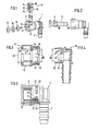
- the quick coupling shown in the figures consists, as shown in FIG. 1 , of a receiving housing 1 made of plastic with a tubular nozzle 7 for connecting a liquid line, not shown, and a cylindrical receiving space 6 for inserting and coupling a tubular male part 3 with a circumferential retaining rib 4th (compare Fig. 2, left).
- the plug-in part 3 can in this case be both the end of a stable metal tube which is used, for example, for fuel lines. But it can also just like the receiving housing - made of rigid plastic or other injection molding material, which is in the same manner as the nozzle 7 of the receiving housing connected to a liquid line or formed on a fuel tank or distributor or otherwise secured.
- a holding element 2 made of hard elastic plastic, which is insertable through an opening in the cylindrical housing wall 5 in the receiving space 6 .
- This holding element 2 has two arc-shaped inwardly directed retaining edges 17 , which engage behind the retaining rib 4 after pressing the male part 3 in a known manner and thus the male part 3 in the housing 1 verkuppeln.
- the holding edges 17 are formed for this purpose on two outwardly projecting support body 13 , which in turn immersed in the installed state of the support member 2 in corresponding recesses 12 of the housing wall 5 and there are also held with circular arc-shaped end faces 18 against the insertion.
- the support body 13 are connected at their ends via V-shaped merged spring bars 14 with each other, wherein one of the joints with an approximately rectangular pressure plate 15 is covered, which is slightly narrower in the outer edges than the housing opening 11. Further details of the support member 2 and its latching Effect of inserting the male part 3 are described in EP 0 605 801 B1 , to the contents of which reference is made.
- the receiving housing 1 is inventively formed in two parts and consists, as shown in FIGS. 3 to 5 , of a head part 8 and a base body 16, which is provided in the present embodiment with a right-angled istknicktem nozzle 7 .
- Headpiece 8 and base body 16 are designed to be plugged together and connectable in the axial direction, the head part 8 having on the insertion side a centering ring 19 , which corresponds in its outer diameter D2 to the inner diameter d2 of the base body 16 .
- an outer sleeve 21 is formed concentric with the centering ring 19, which pushes in the pressing of the head part 8 to the base body 16 through the outer wall of the 22nd
- the sleeve 21 is provided on its inner side with a latching groove 23 , which can be latched with an integrally formed on the outer wall 22 , circumferential latching edge 24 .
- the latching groove 23 expediently has a plurality of circumferentially uniformly distributed, outwardly open openings 25 , so that the secure engagement of the latching edge 24 can be better controlled.
- the receiving space 6 consists of three stepped sections.
- the portion 6 ' lying in the base body 16 has an inner diameter d1 which corresponds to the outer diameter D1 of the insertion part 3 .
- This second section 6" serves to receive two sealing rings 9 and an intermediate ring 10, which is shown in FIG. 1 front opening 11 and in Fig. 5 are shown in the installed state.
- the third, front section 6 "' is located in the head part 8 and has an inner diameter d3 in the entry area, which corresponds to the outer diameter D3 of the retaining rib 4 .
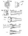
- the housing consists of a head part 30 and a base body 31.
- the head part also has a latching sleeve 26, which is formed in contrast to the embodiment of FIG. 3 on the centering ring 19 and at its free End has an outwardly projecting bead 27 .
- a groove 28 is provided, which is adapted to the bead 27 in width and depth.
- the latching sleeve 26 is interrupted from its front side 20 over the entire length by a plurality of slots 29 distributed uniformly over the circumference.
- This type of locking the head portion 30 in the base body 31 in addition to the rotatability has the further advantage that after insertion of the male part 3 in the receiving space 6, the slotted locking sleeve 26 is supported inwardly, so that the bead 27 is securely anchored in the groove 28 and the headboard is secured against high pull-off forces.
Description
- Die Erfindung betrifft eine lösbare Schnellkupplung gemäß dem Oberbegriff der Patentansprüche 1, und 3.
- Eine derartige lösbare Schnellkupplung ist aus der EP-B-0 605 801 bekannt. Derartige Schnellkupplungen werden u.a. im Kraftfahrzeugbau verwendet, um Kraftstoffleitungen untereinander oder mit an Kraftstoffbehälter oder -verteiler angeformten oder sonstwie befestigten Einsteckteilen zu verbinden. Hierbei kommt es nicht nur auf eine einfache und montagefreundliche Handhabung sowie eine absolut dichte Verbindung nach dem Einrasten des Einsteckteils im Kupplungsgehäuse an, sondern die Kupplung muß sich im Bedarfsfall auch wieder leicht lösen lassen, was mit der Erfindung zugrundeliegenden Schnellkupplung hervorragend erreicht wird.
- Die Form des Kupplungsgehäuses wird hierbei unter anderem bestimmt von den örtlichen Gegebenheiten an der Anschlußstelle, wobei die Gehäuse nicht immer in geradliniger Verlängerung vom Einsteckteil ausgeführt werden können, sondern aufgrund beengter Platzverhältnisse und der Verlegungsrichtung der Kraftstoffleitungen auch abgewinkelte Formen benötigt werden. Dabei kann es passieren, daß die Druckplatten der Halteelemente nur schwer zugänglich sind und die Kupplung nicht ohne weiteres gelöst werden kann.
- Aus US-A-5,542,717 ist eine Schnellkupplung bekannt, bei der ein in ein Aufnahmegehäuse einfügbares Einsteckteil über eine zylinderförmige Kappe unlösbar mit dem Aufnahmegehäuse verbindbar ist, wobei die zylinderförmige Kappe über eine umfänglich angeordnete, Rastrillen und Rastkanten aufweisende Rastverbindung drehbar mit dem Aufnahmegehäuse verbunden ist.
- Der Erfindung liegt die Aufgabe zugrunde, eine lösbare Schnellkupplung der eingangs genannten Art anzugeben, bei der auch bei einer abgewinkelte Ausgestaltung das Halteelement zum Lösen der Verbindung zwischen dem Aufnahmegehäuse und dem Einsteckteil einfach zugänglich ist und das Aufnahmegehäuse weiterhin stabil ist.
- Diese Aufgabe wird bei einer lösbaren Schnellkupplung der eingangs genannten Art erfindungsgemäß in verschiedenen Ausgestaltungen mit den kennzeichnenden Merkmalen der Patentansprüche 1 und 3 gelöst.
- Durch die erfindungsgemäßen zweiteiligen Ausgestaltungen des Aufnahmegehäuses lässt sich das das Halteelement aufnehmende Kopfteil gegenüber dem Grundkörper verdrehen, so dass das Halteelement für ein einfaches Betätigen positionierbar ist, wobei Elemente des Grundkörpers und des Kopfteiles so miteinander in Eingriff sind, dass sich eine hohe Stabilität insbesondere gegenüber einem Verkippen des Kopfteiles und des Grundkörpers in Bezug aufeinander ergibt-Hierbei sind zur Herstellung der Steckverbindung zwei Möglichkeiten vorgesehen, welche in der Zeichnung dargestellt sind und anhand der nachfolgenden Zeichnungsbeschreibung näher erläutert werden sollen.
- Es zeigt
- Fig. 1
- das Aufnahmegehäuse einer Schnellkupplung mit Einbauteilen in einer perspektivischen Explosionsdarstellung,
- Fig. 2
- das Aufnahmegehäuse mit Einsteckteil vor dem Eindrücken,
- Fig. 3
- das Kopfteil eines zweigeteilten Aufnahmegehäuses im Schnitt,
- Fig. 4
- der zugehörige Grundkörper im Schnitt,
- Fig. 5
- das zusammengesteckte Aufnahmegehäuse in Seitenansicht mit Teilschnitt im Verrastungsbereich,
- Fig. 6
- das Kopfteil einer anderen Ausführungsform eines zweigeteilten Aufnahmegehäuses in einer Ansicht in Richtung des Pfeiles A,
- Fig. 7
- das gleiche Kopfteil in Seitenansicht,
- Fig. 8
- einen Schnitt durch das Kopfteil gemäß Linie VIII - VIII in Fig. 6,
- Fig. 9
- der zugehörige Grundkörper im Längsschnitt,
- Fig. 10
- einen Längsschnitt durch das Aufnahmegehäuse im zusammengebauten Zustand,
- Fig. 11
- das gleiche Aufnahmegehäuse mit Einbauteilen im fertig montierten Zustand mit Einsteckteil vor dem Eindrücken und
- Fig. 12
- das gleiche Aufnahmegehäuse nach dem Eindrücken des Einsteckteils, wobei die Schnittebene um 90° gedreht ist.
- Die in den Figuren dargestellte Schnellkupplung besteht, wie aus Fig. 1 ersichtlich, aus einem Aufnahmegehäuse 1 aus Kunststoff mit einem rohrförmigen Stutzen 7 zum Anschluß einer nicht dargestellten Flüssigkeitsleitung und einem zylindrischen Aufnahmeraum 6 zum Einführen und Verkuppeln eines rohrförmigen Einsteckteils 3 mit einer umlaufenden Halterippe 4 (vergleiche Fig. 2, links).
- Das Einsteckteil 3 kann hierbei sowohl das Ende eines stabilen Metallrohres sein, welches beispielsweise für Kraftstoffleitungen verwendet wird. Es kann aber auch genau wie das Aufnahmegehäuse - aus starrem Kunststoff oder anderem Spritzgießmaterial bestehen, welches in gleicher Weise wie der Stutzen 7 des Aufnahmegehäuses mit einer Flüssigkeitsleitung verbindbar ist oder aber an einem Kraftstoffbehälter bzw. -verteiler angeformt oder in sonstiger Weise befestigt ist.
- Im vorderen Bereich des Aufnahmeraums 6 befindet sich ein Halteelement 2 aus hartelastischem Kunststoff, welches durch eine Öffnung in der zylindrischen Gehäusewand 5 in den Aufnahmeraum 6 einführbar ist. Dieses Halteelement 2 weist zwei kreisbogenförmig nach innen gerichtete Haltekanten 17 auf, weiche die Halterippe 4 nach dem Eindrücken des Einsteckteils 3 in bekannter Weise hintergreifen und so das Einsteckteil 3 im Gehäuse 1 verkuppeln.
- Die Haltekanten 17 sind zu diesem Zweck an zwei nach außen abstehende Stützkörper 13 angeformt, welche ihrerseits im eingebauten Zustand des Halteelements 2 in entsprechende Aussparungen 12 der Gehäusewand 5 eintauchen und dort mit ebenfalls kreisbogenförmigen Stirnflächen 18 entgegen der Einsteckrichtung gehalten werden. Die Stützkörper 13 sind an ihren Enden über V-förmig zusammengeführte Federstege 14 untereinander verbunden, wobei eine der Verbindungsstellen mit einer etwa rechteckigen Druckplatte 15 abgedeckt ist, welche in den Außenkanten geringfügig schmaler ist als die Gehäuseöffnung 11. Weitere Einzelheiten des Halteelements 2 sowie dessen verrastende Wirkung beim Einführen des Einsteckteils 3 sind in der EP 0 605 801 B1 beschrieben, auf deren Inhalt Bezug genommen wird.
- Das Aufnahmegehäuse 1 ist erfindungsgemäß zweiteilig ausgebildet und besteht, wie aus Fig. 3 bis 5 ersichtlich, aus einem Kopfteil 8 und einem Grundkörper 16, welcher im vorliegenden Ausführungsbeispiel mit einem rechtwinklig abgeknicktem Stutzen 7 versehen ist. Kopfleil 8 und Grundkörper 16 sind in axialer Richtung zusammensteckbar und verbindbar ausgebildet, wobei das Kopfteil 8 an der Einsteckseite einen Zentrierring 19 aufweist, welcher in seinem Außendurchmesser D2 dem Innendurchmesser d2 des Grundkörpers 16 entspricht.
- Am Kopfteil 8 ist konzentrisch zum Zentrierring 19 eine äußere Hülse 21 angeformt, welche sich beim Andrücken des Kopfteils 8 an den Grundkörper 16 über dessen Außenwand 22 schiebt. Die Hülse 21 ist an ihrer Innenseite mit einer Rastrille 23 versehen, welche mit einer an der Außenwand 22 angeformten, umlaufenden Rastkante 24 verrastbar ist. Die Rastrille 23 weist zweckmäßigerweise mehrere, über den Umfang gleichmäßig verteilte, nach außen offene Durchbrüche 25 auf, damit das sichere Einrasten der Rastkante 24 besser kontrolliert werden kann.
- Wie aus Fig. 3 und 4 ersichtlich, besteht der Aufnahmeraum 6 aus drei stufenweise abgesetzten Abschnitten. Hierbei weist der im Grundkörper 16 innenliegende Abschnitt 6' einen Innendurchmesser d1 auf, welcher dem Außendurchmesser D1 des Einsteckteils 3 entspricht. Dem schließt sich nach außen, d.h. zur Einsteckseite hin, ein zweiter Abschnitt 6" an, dessen Innendurchmesser d2 dem Außendurchmesser D2 des Zentrierrings 19 entspricht. Dieser zweite Abschnitt 6" dient zur Aufnahme von zwei Dichtungsringen 9 sowie einem Zwischenring 10, welche in Fig. 1 vorder Öffnung 11 und in Fig. 5 im eingebauten Zustand dargestellt sind. Der dritte, vordere Abschnitt 6"' befindet sich im Kopfteil 8 und weist im Eingangsbereich einen Innendurchmesser d3 auf, welcher dem Außendurchmesser D3 der Halterippe 4 entspricht.
- Bei dem in den Fig. 6 bis 12 dargestellten Ausführungsbeispiel besteht das Gehäuse aus einem Kopfteil 30 und einem Grundkörper 31. Das Kopfteil besitzt ebenfalls eine Rasthülse 26, welche aber im Unterschied zum Ausführungsbeispiel nach Fig. 3 am Zentrierring 19 angeformt ist und an ihrem freien Ende einen nach außen abstehenden Wulst 27 aufweist. Dementsprechend ist am Grundkörper 31 vor dem Ende des mittleren Abschnitts 6" ein Einführbereich 32 vorgelagert, und am Ende des Abschnitts 6" eine Rille 28 vorgesehen, weiche in Breite und Tiefe dem Wulst 27 angepaßt ist.
- Beim Zusammenfügen von Kopfteil 30 und Grundkörper 31 rastet der Wulst 27 in die Rille 28 des Grundkörpers 31 ein, während gleichzeitig der Zentrierring 19 in eine entsprechende Zentrierhülse 33 am Anfang des Einführbereichs 32 eingreift.
- Damit sich die Rasthülse 26 beim Eindrücken in den trichterförmigen Einführbereich 23 leichter zusammenziehen kann, ist die Rasthülse 26 von ihrer Stirnseite 20 ab über die ganze Länge durch mehrere über den Umfang gleichmäßig verteilte Schlitze 29 unterbrochen.
- Diese Art der Verrastung des Kopfteils 30 im Grundkörper 31 hat neben der Verdrehbarkeit den weiteren Vorteil, daß nach dem Einführen des Einsteckteils 3 in den Aufnahmeraum 6 die geschlitzte Rasthülse 26 nach innen abgestützt ist, so daß der Wulst 27 in der Rille 28 sicher verankert ist und das Kopfteil gegen hohe Abzugskräfte gesichert ist.
Claims (4)
- Lösbare Schnellkupplung zur Aufnahme eines rohrförmigen Einsteckteils (3) mit einer umlaufenden Halterippe (4), bestehend aus einem Aufnahmegehäuse (1) mit einem ebenfalls rohrförmigen Stutzen (7) zum Anschluß einer Flüssigkeitsleitung und einem zylindrischen Aufnahmeraum (6) zum Einführen des Einsteckteils (3) sowie aus einem separaten Halteelement (2) aus hartelastischem Kunststoff mit kreisbogenförmig nach innen gerichteten, elastisch auffederbaren Haltekanten (17) zum Hintergreifen der Halterippe (4) nach dem Eindrücken des Einsteckteils (3), wobei das Halteelement (2) durch eine Öffnung (11) in der zylindrischen Gehäusewand (5) des Aufnahmegehäuses (1) in den Aufnahmeraum (6) einführbar, mit den Haltekanten (17) in axialer Richtung zur Gehäusewand (5) festlegbar und zum Lösen des Einsteckteils (3) im Öffnungsbereich (11) der Gehäusewand (5) von außen eindrückbar ist und wobei der Aufnahmeraum (6) aus drei stufenweise abgesetzten Abschnitten besteht, wovon der erste, innenliegende Abschnitt (6') im Innendurchmesser (d1) dem Außendurchmesser (D1) des Einsteckteils (3) entspricht, der zweite, sich nach außen hin anschließende mittlere Abschnitt (6") zur Aufnahme von mindestens einem Dichtungsring (9) für das Einsteckteil (3) bestimmt ist und der dritte, vordere Abschnitt (6"') im Eingangsbereich einen Innendurchmesser (d3) entsprechend dem Außendurchmesser (D3) der Halterippe (4) aufweist, dadurch gekennzeichnet, daß das Aufnahmegehäuse (1) zweiteilig mit einem Kopfteil (8, 30) und mit einem Grundkörper (16, 31) ausgebildet ist, daß das den vorderen Abschnitt (6"') enthaltende und das Halteelement (2) aufnehmende Kopfteil (8, 30) mit dem Grundkörper (16, 31) in axialer Richtung zusammensteckbar und, verbindba ist und an der Einsteckseite mit einem Zentrierring (19) ausgebildet ist, welcher in seinem Außendurchmesser (D2) dem Innendurchmesser (d2) des Grundkörpers (16) entspricht und dessen Stirnfläche (20) gleichzeitig als Abschluß für den mittleren Abschnitt (6") dient, daß die Verbindung durch Rastelemente (23/24 beziehungsweise 27/28) derart hergestellt ist, daß das Kopfteil (8,30) auf einer Außenwand (22) des Grundkörpers (16, 31) verdrehbar gehalten ist, wobei am Kopfteil (8) konzentrisch zum Zentrierring (19) eine äußere Hülse (21) angeformt ist, welche sich beim Andrücken des Kopfteils (8) an den Grundkörper (16) über dessen Außenwand (22) unter Anlage der Innenseite der Außenwand (22) des Grundkörpers (16) an der Außenseite des Zentrierringes (19) schiebt, und wobei das Kopfteil (8) an seiner Innenseite mit einer Rastrille (23) versehen ist, die mit einer an der Außenwand (22) des Grundkörpers (16) angeformten, umlaufenden Rastkante (24) verrastbar ist.
- Lösbare Schnellkupplung nach Anspruch 1, dadurch gekennzeichnet, daß die Rastrille (23) mehrere, über den Umfang gleichmäßig verteilte, nach außen offene Durchbrüche (25) aufweist.
- Lösbare Schnellkupplung zur Aufnahme eines rohrförmigen Einsteckteils (3) mit einer umlaufenden Halterippe (4), bestehend aus einem Aufnahmegehäuse (1) mit einem ebenfalls rohrförmigen Stutzen (7) zum Anschluß einer Flüssigkeitsleitung und einem zylindrischen Aufnahmeraum (6) zum Einführen des Einsteckteils (3) sowie aus einem separaten Halteelement (2) aus hartelastischem Kunststoff mit kreisbogenförmig nach innen gerichteten, elastisch auffederbaren Haltekanten (17) zum Hintergreifen der Halterippe (4) nach dem Eindrücken des Einsteckteils (3), wobei das Halteelement (2) durch eine Öffnung (11) in der zylindrischen Gehäusewand (5) des Aufnahmegehäuses (1) in den Aufnahmeraum (6) einführbar, mit den Haltekanten (17) in axialer Richtung zur Gehäusewand (5) festlegbar und zum Lösen des Einsteckteils (3) im Öffnungsbereich (11) der Gehäusewand (5) von außen eindrückbar ist und wobei der Aufnahmeraum (6) aus drei stufenweise abgesetzten Abschnitten besteht, wovon der erste, innenliegende Abschnitt (6') im Innendurchmesser (d1) dem Außendurchmesser (D1) des Einsteckteils (3) entspricht, der zweite, sich nach außen hin anschließende mittlere Abschnitt (6") zur Aufnahme von mindestens einem Dichtungsring (9) für das Einsteckteil (3) bestimmt ist und der dritte, vordere Abschnitt (6"') im Eingangsbereich einen Innendurchmesser (d3) entsprechend dem Außendurchmesser (D3) der Halterippe (4) aufweist, dadurch gekennzeichnet , daß das Aufnahmegehäuse (1) zweiteilig mit einem Kopfteil (8, 30) und mit einem Grundkörper (16, 31) ausgebildet ist, daß das den vorderen Abschnitt (6"') enthaltende und das Halteelement (2) aufnehmende Kopfteil (8, 30) mit dem Grundkörper (16, 31) in axialer Richtung zusammensteckbar und verbindbar ist und an der Einsteckseite mit einem Zentrierring (19) ausgebildet ist dessen Stirnfläche (20) gleichzeitig als Abschluß für den mittleren Abschnitt (6") dient, daß die Verbindung durch Rastelemente (23/24 beziehungsweise 27/28) derart hergestellt ist, daß das Kopfteil (8,30) auf einer Außenwand (22) des Grundkörpers (16, 31) verdrehbar gehalten ist, wobei am Zentrierring (19) des Kopfteils (30) eine Rasthülse (26) angeformt ist, die an ihrem freien Ende einen nach außen abstehenden Wulst (27) aufweist, welcher in eine entsprechend breite und tiefe Rille (28) des Grundkörpers (31) am Ende des mittleren Abschnitts (6") einrastbar ist, wobei der Zentrierring (19) in eine am Anfang eines am Grundkörper (31) vor dem Ende des mittleren Abschnitts (6'') vorgelagerten Einführbereiches (32) angeordnete Zentrierhülse (33) eingreift.
- Lösbare Schnellkupplung nach Anspruch 3, dadurch gekennzeichnet, daß die Rasthülse (25) von ihrer Stirnseite (20) ab über die ganze Länge durch mehrere, über den Umfang verteilte Schlitze (29) unterbrochen ist.
Applications Claiming Priority (3)
| Application Number | Priority Date | Filing Date | Title |
|---|---|---|---|
| DE19722842 | 1997-05-30 | ||
| DE19722842A DE19722842C2 (de) | 1997-05-30 | 1997-05-30 | Lösbare Schnellkupplung |
| PCT/EP1998/002815 WO1998054503A1 (de) | 1997-05-30 | 1998-05-13 | Lösbare schnellkupplung |
Publications (3)
| Publication Number | Publication Date |
|---|---|
| EP0983462A1 EP0983462A1 (de) | 2000-03-08 |
| EP0983462B1 EP0983462B1 (de) | 2001-10-17 |
| EP0983462B2 true EP0983462B2 (de) | 2006-08-30 |
Family
ID=7831035
Family Applications (1)
| Application Number | Title | Priority Date | Filing Date |
|---|---|---|---|
| EP98930686A Expired - Lifetime EP0983462B2 (de) | 1997-05-30 | 1998-05-13 | Lösbare schnellkupplung |
Country Status (10)
| Country | Link |
|---|---|
| US (1) | US6318764B1 (de) |
| EP (1) | EP0983462B2 (de) |
| JP (1) | JP3366338B2 (de) |
| KR (1) | KR100528871B1 (de) |
| AT (1) | ATE207193T1 (de) |
| BR (1) | BR9809534A (de) |
| DE (2) | DE19722842C2 (de) |
| ES (1) | ES2165172T3 (de) |
| PT (1) | PT983462E (de) |
| WO (1) | WO1998054503A1 (de) |
Cited By (2)
| Publication number | Priority date | Publication date | Assignee | Title |
|---|---|---|---|---|
| US7878552B2 (en) | 2008-03-11 | 2011-02-01 | A. Kayser Automotive Systems Gmbh | Insert coupling |
| DE102018121293A1 (de) * | 2018-08-31 | 2020-03-05 | Schlemmer Holding GmbH | Kupplungsvorrichtung und wellschlauchanordnung |
Families Citing this family (81)
| Publication number | Priority date | Publication date | Assignee | Title |
|---|---|---|---|---|
| DE19809313C1 (de) * | 1998-03-05 | 1999-08-12 | Raymond A & Cie | Verbindungseinheit einer lösbaren Schnellkupplung für Metalleitungen |
| KR100331471B1 (ko) * | 1999-11-16 | 2002-04-09 | 황현식 | 차량용 연료관의 컨넥터 |
| DE10001100A1 (de) * | 2000-01-13 | 2001-07-26 | Itt Mfg Enterprises Inc | Kupplungsgehäuse und Schnellkupplung für Schläuche oder Rohrleitungen in Kraftfahrzeugen in Verbundbauweise |
| US6302451B1 (en) * | 2000-03-15 | 2001-10-16 | Dana Corporation | Quick-connect hose end couplings |
| US6612622B2 (en) * | 2000-04-06 | 2003-09-02 | Itt Manufacturing Enterprises, Inc. | Rotatable quick connector |
| DE10025817C2 (de) * | 2000-05-24 | 2002-06-20 | Raymond A & Cie | Lösbare Schnellkupplung mit Sicherheitsverrastung |
| FR2818731B1 (fr) * | 2000-12-22 | 2006-11-03 | Legris Sa | Coupleur rapide avec temoin de connexion |
| US20030137148A1 (en) * | 2000-12-27 | 2003-07-24 | Andre Michael J. | Fluid quick connector with non-rotation conduit engaging ribs |
| DE10126205C1 (de) * | 2001-05-30 | 2002-04-04 | Raymond A & Cie | Lösbare Steckkupplung mit Schutzhülse |
| US7073688B2 (en) * | 2001-10-09 | 2006-07-11 | Camelbak Products, Llc | Personal hydration system with component connectivity |
| US20060231561A1 (en) * | 2001-10-09 | 2006-10-19 | Robert Choi | Personal hydration system with component connectivity |
| US20040089301A1 (en) * | 2001-10-09 | 2004-05-13 | Robert Choi | Personal hydration system with component connectivity |
| US6908015B2 (en) | 2001-10-09 | 2005-06-21 | Camelbak Products, Llc | Personal hydration system with component connectivity |
| US8113547B2 (en) * | 2002-03-22 | 2012-02-14 | Cooper Standard Automotive Inc. | Snap mount fluid quick connector |
| US7029036B2 (en) * | 2004-03-09 | 2006-04-18 | Itt Manufacturing Enterprises, Inc. | Rotatable two part quick connection |
| FR2847330A1 (fr) * | 2002-11-19 | 2004-05-21 | Staubli Sa Ets | Raccord rapide pour la jonction amovible de deux canalisations |
| US20050082828A1 (en) | 2003-09-12 | 2005-04-21 | Wicks Jeffrey C. | Releasable connection assembly for joining tubing sections |
| US7413366B2 (en) * | 2003-12-09 | 2008-08-19 | Unger Marketing International, Llc | Connecting members and methods for connecting implements to extension poles |
| DE102004052475A1 (de) * | 2004-10-28 | 2006-05-04 | Eaton Fluid Power Gmbh | Zugfeste Steckkupplung |
| DE102004054467A1 (de) * | 2004-11-11 | 2006-05-24 | A. Raymond & Cie | Sicherungsteil für eine Schnellkupplung |
| US7806213B2 (en) | 2004-12-17 | 2010-10-05 | Tokai Rubber Industries, Ltd. | Piping structure for transporting a fuel |
| JP2006194433A (ja) * | 2004-12-17 | 2006-07-27 | Tokai Rubber Ind Ltd | 燃料輸送用のコネクタ付き樹脂チューブの組付構造及びこれに用いるコネクタ付き樹脂チューブ |
| DE102004062207B3 (de) * | 2004-12-23 | 2005-10-20 | Kirchner Fraenk Rohr | Verbindungseinrichtung |
| DE102005010664A1 (de) * | 2005-03-08 | 2006-09-14 | Siemens Ag | Verbindungselement zum Transport von gasförmigen, flüssigen oder festen Stoffen |
| US7448653B2 (en) | 2005-06-10 | 2008-11-11 | Value Plastics, Inc. | Female connector for releasable coupling with a male connector defining a fluid conduit |
| FR2891889B1 (fr) * | 2005-10-07 | 2009-03-06 | Caillau Ets | Embout de connexion etanche et piece terminale pour un tel embout |
| US7806139B2 (en) | 2006-01-20 | 2010-10-05 | Value Plastics, Inc. | Fluid conduit coupling assembly having male and female couplers with integral valves |
| US7552948B2 (en) * | 2006-03-29 | 2009-06-30 | Tokai Rubber Industries, Ltd. | Quick connector |
| US7497480B2 (en) * | 2006-04-07 | 2009-03-03 | Ti Group Automotive Systems, Llc | Hybrid quick connector |
| DE102006034174A1 (de) * | 2006-07-24 | 2008-01-31 | Siemens Ag | Vorrichtung zum Verbinden zweier kraftstoffführender Bauteile |
| US7731245B2 (en) * | 2006-10-06 | 2010-06-08 | Ti Group Automotive Systems, Llc | Quick connector coupling |
| US20090058082A1 (en) * | 2007-09-05 | 2009-03-05 | Green Ronald D | Two-part quick connect retention attachment for flexible tubing in a water supply system |
| USD654573S1 (en) | 2007-11-19 | 2012-02-21 | Value Plastics, Inc. | Female quick connect fitting |
| USD634840S1 (en) | 2008-07-03 | 2011-03-22 | Value Plastics, Inc. | Female body of connector for fluid tubing |
| US8235426B2 (en) | 2008-07-03 | 2012-08-07 | Nordson Corporation | Latch assembly for joining two conduits |
| USD629894S1 (en) | 2008-07-03 | 2010-12-28 | Value Plastics, Inc. | Male body of connector for fluid tubing |
| USD630320S1 (en) | 2008-07-03 | 2011-01-04 | Value Plastics, Inc. | Connector for fluid tubing |
| FR2935167A1 (fr) * | 2008-08-20 | 2010-02-26 | Legris Sa | Raccord en deux parties reliees par baionette, partie de corps d'un tel raccord et procede de renforcement de la liaison de parties de corps d'un tel raccord |
| WO2010025210A1 (en) * | 2008-08-29 | 2010-03-04 | Ti Group Automotive Systems, Llc | Vehicular climate control system |
| USD655393S1 (en) | 2009-06-23 | 2012-03-06 | Value Plastics, Inc. | Multi-port valve |
| DE102009050076B3 (de) | 2009-10-20 | 2011-04-07 | A. Kayser Automotive Systems Gmbh | Einsteckkupplung |
| USD649240S1 (en) | 2009-12-09 | 2011-11-22 | Value Plastics, Inc. | Male dual lumen bayonet connector |
| US10711930B2 (en) | 2009-12-09 | 2020-07-14 | Nordson Corporation | Releasable connection assembly |
| US9388929B2 (en) | 2009-12-09 | 2016-07-12 | Nordson Corporation | Male bayonet connector |
| USD783815S1 (en) | 2009-12-09 | 2017-04-11 | General Electric Company | Male dual lumen bayonet connector |
| USD650478S1 (en) | 2009-12-23 | 2011-12-13 | Value Plastics, Inc. | Female dual lumen connector |
| EP2516914B1 (de) | 2009-12-23 | 2018-09-05 | General Electric Company | Knopfverriegelung mit einteilig geformten cantileverfedern |
| JP5714028B2 (ja) | 2009-12-23 | 2015-05-07 | ノードソン コーポレーションNordson Corporation | 外形引込み部を有する流体コネクターラッチ |
| US10441120B1 (en) | 2010-04-30 | 2019-10-15 | Unger Marketing International, Llc | Universal connecting members |
| EP2612402B1 (de) | 2010-08-31 | 2018-10-10 | A. RAYMOND et Cie | Schnellkupplung mit einem sensorgehäuse |
| US8408425B2 (en) * | 2010-09-07 | 2013-04-02 | Chien-Ping Lien | Hydration device |
| US9624089B1 (en) | 2010-11-11 | 2017-04-18 | Arctic Innovations, Llc | Cold weather hydration systems, devices, components and methods |
| USD652510S1 (en) | 2011-02-11 | 2012-01-17 | Value Plastics, Inc. | Connector for fluid tubing |
| USD663022S1 (en) | 2011-02-11 | 2012-07-03 | Nordson Corporation | Male body of connector for fluid tubing |
| USD652511S1 (en) | 2011-02-11 | 2012-01-17 | Value Plastics, Inc. | Female body of connector for fluid tubing |
| JP6140691B2 (ja) | 2011-06-02 | 2017-05-31 | ア レイモン エ シーA. Raymond Et Cie | 三次元印刷で製造されたコネクタ |
| USD698440S1 (en) | 2011-07-29 | 2014-01-28 | Nordson Corporation | Connector for fluid tubing |
| USD699840S1 (en) | 2011-07-29 | 2014-02-18 | Nordson Corporation | Male body of connector for fluid tubing |
| USD699841S1 (en) | 2011-07-29 | 2014-02-18 | Nordson Corporation | Female body of connector for fluid tubing |
| DE102011089099A1 (de) | 2011-12-20 | 2013-06-20 | Bayerische Motoren Werke Aktiengesellschaft | Verbindungseinheit und eine derartige Verbindungseinheit umfassende Verbindungsanordnung zur Herstellung einer unlösbaren Verbindung medienführender Leitungen |
| DE102011089100A1 (de) * | 2011-12-20 | 2013-06-20 | Fränkische Industrial Pipes GmbH & Co. KG | Verbindungseinheit und eine derartige Verbindungseinheit umfassende Verbindungsanordnung zur Herstellung einer unlösbaren Verbindung medienführender Leitungen |
| USD709612S1 (en) | 2011-12-23 | 2014-07-22 | Nordson Corporation | Female dual lumen connector |
| EP2728236B1 (de) * | 2012-11-05 | 2017-04-19 | TI Automotive (Fuldabrück) GmbH | Schnellkupplung |
| CA2929476C (en) | 2013-11-06 | 2019-01-22 | Becton Dickinson and Company Limited | System for closed transfer of fluids with a locking member |
| US9528644B2 (en) * | 2013-12-12 | 2016-12-27 | Zoje Kitchen & Bath Co. Ltd. | Quick connector assembly |
| DE102015003792B4 (de) * | 2015-03-23 | 2021-08-26 | A. Kayser Automotive Systems Gmbh | Kupplungsvorrichtung |
| DE102016001610A1 (de) * | 2016-02-12 | 2017-08-17 | A. Kayser Automotive Systems Gmbh | Einsteckkupplung |
| DE212016000272U1 (de) * | 2016-03-11 | 2018-10-26 | Edwards Korea Limited | Schnellverbinder |
| ES2645929B1 (es) * | 2016-06-06 | 2018-09-20 | Industrie Ilpea España, S.A. | Conector rápido para canalizaciones |
| DE102016111194A1 (de) * | 2016-06-20 | 2017-12-21 | Voss Automotive Gmbh | Kupplungsteil für einen Steckverbinder zur Herstellung von Schlauch- und/oder Rohrverbindungen und Steckverbinder mit einem derartigen Kupplungsteil |
| CN107542989A (zh) * | 2016-06-23 | 2018-01-05 | 重庆快联汽车零部件有限公司 | 一种快装接头 |
| USD838366S1 (en) | 2016-10-31 | 2019-01-15 | Nordson Corporation | Blood pressure connector |
| CN109404647A (zh) * | 2017-08-17 | 2019-03-01 | A.雷蒙德公司 | 可拆卸的快速连接装置 |
| WO2019033952A1 (zh) * | 2017-08-17 | 2019-02-21 | A.雷蒙德公司 | 可拆卸的快速连接装置 |
| USD859618S1 (en) | 2017-09-15 | 2019-09-10 | Pentair Water Pool And Spa, Inc. | Heating apparatus clip |
| US10612707B2 (en) * | 2017-11-28 | 2020-04-07 | Cooper-Standard Automotive, Inc. | Quick connect assembly and method |
| US11199281B2 (en) | 2018-01-31 | 2021-12-14 | A. Raymond Et Cie. | Dual-latch quick connector |
| USD896626S1 (en) | 2019-02-28 | 2020-09-22 | Unger Marketing International, Llc | Tool connector |
| US11796099B2 (en) * | 2019-08-22 | 2023-10-24 | Cooper-Standard Automotive Inc. | Connector having a pilot with an indicator |
| USD995208S1 (en) | 2021-05-13 | 2023-08-15 | Hydrapak Llc | Beverage container adapter |
| US11821558B2 (en) * | 2021-09-08 | 2023-11-21 | Cooper-Standard Automotive Inc. | Fluid connector with dry break |
Citations (6)
| Publication number | Priority date | Publication date | Assignee | Title |
|---|---|---|---|---|
| CH643931A5 (de) † | 1979-01-18 | 1984-06-29 | Aeroquip Ag | Steckverbindung fuer druckleitungen. |
| DE8407268U1 (de) † | 1984-03-09 | 1984-07-12 | Aesculap-Werke Ag Vormals Jetter & Scheerer, 7200 Tuttlingen | Schlauchkupplung, insbesondere fuer saugschlaeuche an chirurgischen geraeten |
| DE3741250A1 (de) † | 1987-12-05 | 1989-06-15 | Voss Armaturen | Vorrichtung zum gegenseitigen verbinden von zwei leitungen, insbesondere kraftstoffleitungen |
| DE4107603C1 (de) † | 1991-03-09 | 1992-02-06 | Rasmussen Gmbh, 6457 Maintal, De | |
| DE3790414C2 (de) † | 1986-07-17 | 1995-12-21 | Nitodan As | Schnellkupplung für Schläuche oder Rohre |
| US5542717A (en) † | 1994-01-03 | 1996-08-06 | Form Rite, Corporation | Quick connect coupling |
Family Cites Families (14)
| Publication number | Priority date | Publication date | Assignee | Title |
|---|---|---|---|---|
| DE2611233A1 (de) * | 1976-03-17 | 1977-09-22 | Rolf Dieter Ing Grad Reubelt | Schlauchverschraubung |
| US5069489A (en) * | 1980-10-29 | 1991-12-03 | Proprietary Technology, Inc. | Bleed-down connector assembly |
| IL78369A (en) * | 1986-03-31 | 1990-04-29 | Noam Lemelshtrich | Quick-attachable connectors particularly for use as a hose coupler |
| JPH0618123Y2 (ja) * | 1989-11-11 | 1994-05-11 | 日東工器株式会社 | 管継手のソケット |
| US4923228A (en) * | 1988-12-12 | 1990-05-08 | Aeroquip Corporation | Integral quick-connect tube connector |
| DE3933591C1 (de) * | 1989-10-07 | 1991-02-07 | Rasmussen Gmbh, 6457 Maintal, De | |
| DE4300037C1 (de) * | 1993-01-02 | 1994-04-21 | Raymond A & Cie | Lösbare Steckverbindung |
| DE4318878A1 (de) * | 1993-06-08 | 1994-12-15 | Kuehner Gmbh & Cie | Kältemittelkupplung zur Verbindung von Kältemittelleitungen |
| US5683117A (en) * | 1995-12-14 | 1997-11-04 | Flex Technologies, Inc. | Retainer clip for a connector |
| DE19619026A1 (de) * | 1996-05-10 | 1997-11-13 | Trinova Gmbh | Schnellkupplung |
| FR2753774B1 (fr) * | 1996-09-24 | 1998-11-20 | Connecteur rapide a verrouillage | |
| DE19708377C1 (de) * | 1997-03-01 | 1998-06-18 | Raymond A & Cie | Lösbare Steckverbindung mit Montageanzeige |
| US6155612A (en) * | 1997-11-17 | 2000-12-05 | Itt Manufacturing Enterprises, Inc. | Hybrid quick connector |
| DE19831897C2 (de) * | 1998-07-16 | 2000-07-06 | Rasmussen Gmbh | Steckkupplung zum Verbinden zweier Fluidleitungen |
-
1997
- 1997-05-30 DE DE19722842A patent/DE19722842C2/de not_active Expired - Lifetime
-
1998
- 1998-05-13 US US09/424,828 patent/US6318764B1/en not_active Expired - Lifetime
- 1998-05-13 JP JP50015999A patent/JP3366338B2/ja not_active Expired - Fee Related
- 1998-05-13 EP EP98930686A patent/EP0983462B2/de not_active Expired - Lifetime
- 1998-05-13 ES ES98930686T patent/ES2165172T3/es not_active Expired - Lifetime
- 1998-05-13 PT PT98930686T patent/PT983462E/pt unknown
- 1998-05-13 BR BR9809534-0A patent/BR9809534A/pt not_active IP Right Cessation
- 1998-05-13 WO PCT/EP1998/002815 patent/WO1998054503A1/de active IP Right Grant
- 1998-05-13 AT AT98930686T patent/ATE207193T1/de not_active IP Right Cessation
- 1998-05-13 DE DE59801789T patent/DE59801789D1/de not_active Expired - Lifetime
- 1998-05-13 KR KR10-1999-7010155A patent/KR100528871B1/ko not_active IP Right Cessation
Patent Citations (6)
| Publication number | Priority date | Publication date | Assignee | Title |
|---|---|---|---|---|
| CH643931A5 (de) † | 1979-01-18 | 1984-06-29 | Aeroquip Ag | Steckverbindung fuer druckleitungen. |
| DE8407268U1 (de) † | 1984-03-09 | 1984-07-12 | Aesculap-Werke Ag Vormals Jetter & Scheerer, 7200 Tuttlingen | Schlauchkupplung, insbesondere fuer saugschlaeuche an chirurgischen geraeten |
| DE3790414C2 (de) † | 1986-07-17 | 1995-12-21 | Nitodan As | Schnellkupplung für Schläuche oder Rohre |
| DE3741250A1 (de) † | 1987-12-05 | 1989-06-15 | Voss Armaturen | Vorrichtung zum gegenseitigen verbinden von zwei leitungen, insbesondere kraftstoffleitungen |
| DE4107603C1 (de) † | 1991-03-09 | 1992-02-06 | Rasmussen Gmbh, 6457 Maintal, De | |
| US5542717A (en) † | 1994-01-03 | 1996-08-06 | Form Rite, Corporation | Quick connect coupling |
Cited By (3)
| Publication number | Priority date | Publication date | Assignee | Title |
|---|---|---|---|---|
| US7878552B2 (en) | 2008-03-11 | 2011-02-01 | A. Kayser Automotive Systems Gmbh | Insert coupling |
| DE102018121293A1 (de) * | 2018-08-31 | 2020-03-05 | Schlemmer Holding GmbH | Kupplungsvorrichtung und wellschlauchanordnung |
| WO2020043488A1 (de) | 2018-08-31 | 2020-03-05 | Schlemmer Holding GmbH | Kupplungsvorrichtung und wellschlauchanordnung |
Also Published As
| Publication number | Publication date |
|---|---|
| KR20010012206A (ko) | 2001-02-15 |
| EP0983462B1 (de) | 2001-10-17 |
| ATE207193T1 (de) | 2001-11-15 |
| ES2165172T3 (es) | 2002-03-01 |
| PT983462E (pt) | 2002-04-29 |
| DE19722842A1 (de) | 1998-12-03 |
| DE19722842C2 (de) | 2001-04-12 |
| JP2000513795A (ja) | 2000-10-17 |
| EP0983462A1 (de) | 2000-03-08 |
| JP3366338B2 (ja) | 2003-01-14 |
| KR100528871B1 (ko) | 2005-11-16 |
| US6318764B1 (en) | 2001-11-20 |
| BR9809534A (pt) | 2000-06-20 |
| DE59801789D1 (de) | 2001-11-22 |
| WO1998054503A1 (de) | 1998-12-03 |
Similar Documents
| Publication | Publication Date | Title |
|---|---|---|
| EP0983462B2 (de) | Lösbare schnellkupplung | |
| DE19809313C1 (de) | Verbindungseinheit einer lösbaren Schnellkupplung für Metalleitungen | |
| EP0906534B1 (de) | Lösbare steckverbindung mit montageanzeige | |
| EP1395771B1 (de) | Lösbare steckkupplung mit schutzhülse | |
| DE4300037C1 (de) | Lösbare Steckverbindung | |
| EP0629806B1 (de) | Kältemittelkupplung zur Verbindung von Kältemittelleitungen | |
| EP1697674B1 (de) | Steckverbinder für medienleitungen | |
| DE3424675C2 (de) | Schlauchkupplung | |
| EP1373779B1 (de) | Lösbare steckkupplung mit zusätzlichem verriegelungselement | |
| DE19540784A1 (de) | Lösbare Steckverbindung zur Aufnahme eines rohrförmigen Einsteckteils | |
| EP0806597A1 (de) | Schnellkupplung | |
| DE10000369A1 (de) | Steckverbindungsvorrichtung | |
| EP1781979A1 (de) | Steckverbindung für fluid-leitungen | |
| DE2503606B2 (de) | Rohrverbinder | |
| EP2606270B1 (de) | Verriegelungselement für einen steckverbinder und steckverbinder mit einem solchen verriegelungselement | |
| EP2050996A1 (de) | Steckbarer und verrastbarer Leitungsverbinder | |
| DE102005044751A1 (de) | Steckverbinder für Medienleitungen | |
| EP0618393B1 (de) | Kupplungseinrichtung für Schlauch- und/oder Rohrleitungen | |
| DE4310795C1 (de) | Steckkupplung | |
| EP3361135A1 (de) | Schnellverbindungsvorrichtung und schnellverbindungssystem | |
| DE3438173A1 (de) | Kupplungsmuffe zum verbinden von zwei rohrleitungsenden | |
| EP0579141A1 (de) | Automatisch montierbare Steckkupplung für Leitungsschläuche in Kraftfahrzeugen | |
| EP1265021B1 (de) | Schutzkappe | |
| EP0379106B1 (de) | Anschlussverbindungsstück | |
| EP0531276A2 (de) | Kabelmuffe |
Legal Events
| Date | Code | Title | Description |
|---|---|---|---|
| PUAI | Public reference made under article 153(3) epc to a published international application that has entered the european phase |
Free format text: ORIGINAL CODE: 0009012 |
|
| 17P | Request for examination filed |
Effective date: 19991007 |
|
| AK | Designated contracting states |
Kind code of ref document: A1 Designated state(s): AT CH DE ES FR GB IT LI NL PT SE |
|
| GRAG | Despatch of communication of intention to grant |
Free format text: ORIGINAL CODE: EPIDOS AGRA |
|
| 17Q | First examination report despatched |
Effective date: 20001215 |
|
| GRAG | Despatch of communication of intention to grant |
Free format text: ORIGINAL CODE: EPIDOS AGRA |
|
| GRAH | Despatch of communication of intention to grant a patent |
Free format text: ORIGINAL CODE: EPIDOS IGRA |
|
| GRAH | Despatch of communication of intention to grant a patent |
Free format text: ORIGINAL CODE: EPIDOS IGRA |
|
| GRAA | (expected) grant |
Free format text: ORIGINAL CODE: 0009210 |
|
| AK | Designated contracting states |
Kind code of ref document: B1 Designated state(s): AT CH DE ES FR GB IT LI NL PT SE |
|
| REF | Corresponds to: |
Ref document number: 207193 Country of ref document: AT Date of ref document: 20011115 Kind code of ref document: T |
|
| REG | Reference to a national code |
Ref country code: CH Ref legal event code: EP |
|
| REF | Corresponds to: |
Ref document number: 59801789 Country of ref document: DE Date of ref document: 20011122 |
|
| REG | Reference to a national code |
Ref country code: CH Ref legal event code: NV Representative=s name: BOVARD AG PATENTANWAELTE |
|
| REG | Reference to a national code |
Ref country code: GB Ref legal event code: IF02 |
|
| ET | Fr: translation filed | ||
| GBT | Gb: translation of ep patent filed (gb section 77(6)(a)/1977) |
Effective date: 20020105 |
|
| REG | Reference to a national code |
Ref country code: ES Ref legal event code: FG2A Ref document number: 2165172 Country of ref document: ES Kind code of ref document: T3 |
|
| REG | Reference to a national code |
Ref country code: PT Ref legal event code: SC4A Free format text: AVAILABILITY OF NATIONAL TRANSLATION Effective date: 20020115 |
|
| PLBQ | Unpublished change to opponent data |
Free format text: ORIGINAL CODE: EPIDOS OPPO |
|
| PLBI | Opposition filed |
Free format text: ORIGINAL CODE: 0009260 |
|
| 26 | Opposition filed |
Opponent name: RASMUSSEN GMBH Effective date: 20020615 |
|
| PLBF | Reply of patent proprietor to notice(s) of opposition |
Free format text: ORIGINAL CODE: EPIDOS OBSO |
|
| NLR1 | Nl: opposition has been filed with the epo |
Opponent name: RASMUSSEN GMBH |
|
| PLBF | Reply of patent proprietor to notice(s) of opposition |
Free format text: ORIGINAL CODE: EPIDOS OBSO |
|
| PGFP | Annual fee paid to national office [announced via postgrant information from national office to epo] |
Ref country code: ES Payment date: 20030310 Year of fee payment: 6 |
|
| PGFP | Annual fee paid to national office [announced via postgrant information from national office to epo] |
Ref country code: PT Payment date: 20030320 Year of fee payment: 6 |
|
| PGFP | Annual fee paid to national office [announced via postgrant information from national office to epo] |
Ref country code: GB Payment date: 20030512 Year of fee payment: 6 |
|
| PG25 | Lapsed in a contracting state [announced via postgrant information from national office to epo] |
Ref country code: GB Free format text: LAPSE BECAUSE OF NON-PAYMENT OF DUE FEES Effective date: 20040513 |
|
| PG25 | Lapsed in a contracting state [announced via postgrant information from national office to epo] |
Ref country code: ES Free format text: LAPSE BECAUSE OF NON-PAYMENT OF DUE FEES Effective date: 20040514 |
|
| PG25 | Lapsed in a contracting state [announced via postgrant information from national office to epo] |
Ref country code: PT Free format text: LAPSE BECAUSE OF NON-PAYMENT OF DUE FEES Effective date: 20041115 |
|
| GBPC | Gb: european patent ceased through non-payment of renewal fee |
Effective date: 20040513 |
|
| REG | Reference to a national code |
Ref country code: PT Ref legal event code: MM4A Effective date: 20041115 |
|
| PG25 | Lapsed in a contracting state [announced via postgrant information from national office to epo] |
Ref country code: IT Free format text: LAPSE BECAUSE OF NON-PAYMENT OF DUE FEES Effective date: 20050513 |
|
| REG | Reference to a national code |
Ref country code: ES Ref legal event code: FD2A Effective date: 20040514 |
|
| PGFP | Annual fee paid to national office [announced via postgrant information from national office to epo] |
Ref country code: CH Payment date: 20060508 Year of fee payment: 9 |
|
| PGFP | Annual fee paid to national office [announced via postgrant information from national office to epo] |
Ref country code: NL Payment date: 20060515 Year of fee payment: 9 |
|
| PGFP | Annual fee paid to national office [announced via postgrant information from national office to epo] |
Ref country code: AT Payment date: 20060517 Year of fee payment: 9 |
|
| PUAH | Patent maintained in amended form |
Free format text: ORIGINAL CODE: 0009272 |
|
| STAA | Information on the status of an ep patent application or granted ep patent |
Free format text: STATUS: PATENT MAINTAINED AS AMENDED |
|
| 27A | Patent maintained in amended form |
Effective date: 20060830 |
|
| AK | Designated contracting states |
Kind code of ref document: B2 Designated state(s): AT CH DE ES FR GB IT LI NL PT SE |
|
| REG | Reference to a national code |
Ref country code: CH Ref legal event code: AEN Free format text: AUFRECHTERHALTUNG DES PATENTES IN GEAENDERTER FORM |
|
| REG | Reference to a national code |
Ref country code: ES Ref legal event code: FD2A Effective date: 20040514 |
|
| NLR2 | Nl: decision of opposition |
Effective date: 20060830 |
|
| REG | Reference to a national code |
Ref country code: SE Ref legal event code: RPEO |
|
| NLR3 | Nl: receipt of modified translations in the netherlands language after an opposition procedure | ||
| EN | Fr: translation not filed | ||
| ET3 | Fr: translation filed ** decision concerning opposition | ||
| REG | Reference to a national code |
Ref country code: FR Ref legal event code: EERR Free format text: CORRECTION DE BOPI 07/19 - BREVETS EUROPEENS DONT LA TRADUCTION N A PAS ETE REMISE A L INPI. IL Y A LIEU DE SUPPRIMER : LA MENTION DE LA NON REMISE. LA REMISE DE LA TRADUCTION EST PUBLIEE DANS LE PRESENT BOPI. |
|
| REG | Reference to a national code |
Ref country code: CH Ref legal event code: PL |
|
| PG25 | Lapsed in a contracting state [announced via postgrant information from national office to epo] |
Ref country code: NL Free format text: LAPSE BECAUSE OF NON-PAYMENT OF DUE FEES Effective date: 20071201 |
|
| NLV4 | Nl: lapsed or anulled due to non-payment of the annual fee |
Effective date: 20071201 |
|
| PG25 | Lapsed in a contracting state [announced via postgrant information from national office to epo] |
Ref country code: CH Free format text: LAPSE BECAUSE OF NON-PAYMENT OF DUE FEES Effective date: 20070531 Ref country code: LI Free format text: LAPSE BECAUSE OF NON-PAYMENT OF DUE FEES Effective date: 20070531 Ref country code: AT Free format text: LAPSE BECAUSE OF NON-PAYMENT OF DUE FEES Effective date: 20070513 |
|
| PLAB | Opposition data, opponent's data or that of the opponent's representative modified |
Free format text: ORIGINAL CODE: 0009299OPPO |
|
| PGFP | Annual fee paid to national office [announced via postgrant information from national office to epo] |
Ref country code: SE Payment date: 20090518 Year of fee payment: 12 |
|
| EUG | Se: european patent has lapsed | ||
| PG25 | Lapsed in a contracting state [announced via postgrant information from national office to epo] |
Ref country code: SE Free format text: LAPSE BECAUSE OF NON-PAYMENT OF DUE FEES Effective date: 20100514 |
|
| REG | Reference to a national code |
Ref country code: DE Ref legal event code: R082 Ref document number: 59801789 Country of ref document: DE |
|
| REG | Reference to a national code |
Ref country code: FR Ref legal event code: PLFP Year of fee payment: 19 |
|
| PGFP | Annual fee paid to national office [announced via postgrant information from national office to epo] |
Ref country code: DE Payment date: 20160520 Year of fee payment: 19 |
|
| PGFP | Annual fee paid to national office [announced via postgrant information from national office to epo] |
Ref country code: FR Payment date: 20160520 Year of fee payment: 19 |
|
| REG | Reference to a national code |
Ref country code: DE Ref legal event code: R119 Ref document number: 59801789 Country of ref document: DE |
|
| REG | Reference to a national code |
Ref country code: FR Ref legal event code: ST Effective date: 20180131 |
|
| PG25 | Lapsed in a contracting state [announced via postgrant information from national office to epo] |
Ref country code: DE Free format text: LAPSE BECAUSE OF NON-PAYMENT OF DUE FEES Effective date: 20171201 |
|
| PG25 | Lapsed in a contracting state [announced via postgrant information from national office to epo] |
Ref country code: FR Free format text: LAPSE BECAUSE OF NON-PAYMENT OF DUE FEES Effective date: 20170531 |