EP0986022A2 - A pointing stick having integral control circuitry - Google Patents
A pointing stick having integral control circuitry Download PDFInfo
- Publication number
- EP0986022A2 EP0986022A2 EP99306778A EP99306778A EP0986022A2 EP 0986022 A2 EP0986022 A2 EP 0986022A2 EP 99306778 A EP99306778 A EP 99306778A EP 99306778 A EP99306778 A EP 99306778A EP 0986022 A2 EP0986022 A2 EP 0986022A2
- Authority
- EP
- European Patent Office
- Prior art keywords
- shaft
- actuator
- signal
- substrate
- circuit board
- Prior art date
- Legal status (The legal status is an assumption and is not a legal conclusion. Google has not performed a legal analysis and makes no representation as to the accuracy of the status listed.)
- Withdrawn
Links
Images


Classifications
-
- G—PHYSICS
- G06—COMPUTING; CALCULATING OR COUNTING
- G06F—ELECTRIC DIGITAL DATA PROCESSING
- G06F3/00—Input arrangements for transferring data to be processed into a form capable of being handled by the computer; Output arrangements for transferring data from processing unit to output unit, e.g. interface arrangements
- G06F3/01—Input arrangements or combined input and output arrangements for interaction between user and computer
- G06F3/02—Input arrangements using manually operated switches, e.g. using keyboards or dials
- G06F3/0202—Constructional details or processes of manufacture of the input device
- G06F3/021—Arrangements integrating additional peripherals in a keyboard, e.g. card or barcode reader, optical scanner
- G06F3/0213—Arrangements providing an integrated pointing device in a keyboard, e.g. trackball, mini-joystick
-
- G—PHYSICS
- G06—COMPUTING; CALCULATING OR COUNTING
- G06F—ELECTRIC DIGITAL DATA PROCESSING
- G06F3/00—Input arrangements for transferring data to be processed into a form capable of being handled by the computer; Output arrangements for transferring data from processing unit to output unit, e.g. interface arrangements
- G06F3/01—Input arrangements or combined input and output arrangements for interaction between user and computer
- G06F3/03—Arrangements for converting the position or the displacement of a member into a coded form
- G06F3/033—Pointing devices displaced or positioned by the user, e.g. mice, trackballs, pens or joysticks; Accessories therefor
- G06F3/0338—Pointing devices displaced or positioned by the user, e.g. mice, trackballs, pens or joysticks; Accessories therefor with detection of limited linear or angular displacement of an operating part of the device from a neutral position, e.g. isotonic or isometric joysticks
-
- G—PHYSICS
- G06—COMPUTING; CALCULATING OR COUNTING
- G06F—ELECTRIC DIGITAL DATA PROCESSING
- G06F3/00—Input arrangements for transferring data to be processed into a form capable of being handled by the computer; Output arrangements for transferring data from processing unit to output unit, e.g. interface arrangements
- G06F3/01—Input arrangements or combined input and output arrangements for interaction between user and computer
- G06F3/03—Arrangements for converting the position or the displacement of a member into a coded form
- G06F3/033—Pointing devices displaced or positioned by the user, e.g. mice, trackballs, pens or joysticks; Accessories therefor
- G06F3/038—Control and interface arrangements therefor, e.g. drivers or device-embedded control circuitry
- G06F3/0383—Signal control means within the pointing device
-
- H—ELECTRICITY
- H01—ELECTRIC ELEMENTS
- H01H—ELECTRIC SWITCHES; RELAYS; SELECTORS; EMERGENCY PROTECTIVE DEVICES
- H01H2221/00—Actuators
- H01H2221/008—Actuators other then push button
- H01H2221/012—Joy stick type
Definitions
- This invention generally relates to a pointing device for controlling the positioning, movement and operation of an electronic device, for example, a cursor on a display screen.
- an electronic device for example, a cursor on a display screen.
- a shaft there is a shaft, a substrate, resistor based strain gages, a printed circuit board and control electronics mounted on the printed circuit board.
- US-A-5894301 relates to a collar mounted pointing stick and has the same assignee as the present invention.
- EP-A-844584 relates to a pointing stick with z-axis actuation and has the same assignee as the present invention.
- EP-A-905600 relates to a unified bodied z-axis pointing stick and has the same assignee as the present invention.
- EP-A-862103 relates to a z-axis pointing stick with ESD protection and has the same assignee as the present invention.
- a small stubby, button-like joystick centrally around the keys of the computer keyboard, specifically at the juncture of the "g,” “h” and “b” keys of the standard "QWERTY” keyboard.
- the joystick also known as a pointing stick, was sensitive to lateral pressure, the amount and direction of which were sensed and input into the computer to cause movement of the cursor, and the speed and direction of cursor movement corresponded to the amount and direction of pressure on the joystick. That manufacturer may also provide two upwardly extending "mouse” or "click” buttons immediately below the space bar.
- the joystick is connected by a flexible cable to a computer mother board where it connects to several electronic circuit devices that amplify and condition the signal coming form the joystick.
- the signal from the joystick is a low level analog signal.
- Electronic devices on the mother board amplify the low level analog signal and convert it to a digital signal.
- the electrical signal coming from the joystick is a low level analog signal.
- the signal travels along the flexible cable it loses some of its amplitude and is skewed due to attenuation of the signal. During travel along the cable, the signal can be corrupted due to coupling from external electromagnetic interference.
- an electronic device for example, a cursor on a display screen.
- a shaft there is a shaft, a substrate, resistor based strain gages, a printed circuit board and control electronics mounted on the printed circuit board.
- the printed circuit board is mounted to a keyboard base.
- the device includes an actuator having a first end, a second end and several strain sensitive resistors mounted on the second end of the actuator for generating an electrical signal representative of force applied to the shaft.
- a printed circuit board has the actuator mounted thereto.
- the printed circuit board has a signal conditioning means, mounted to the printed circuit board, for conditioning the electrical signal.
- the signal conditioning means operates to receive the electrical signal as an input and provides a conditioned signal as an output.
- An electrical connection means is disposed between the printed circuit board and the actuator, for electrically routing the electrical signal to the printed circuit board.
- a keyboard base has the printed circuit board and actuator mounted thereto.
- Fig. 1 is a perspective exploded view of the pointing stick with integral control circuitry.
- Fig. 2 is a cross-sectional view of the pointing stick of Figure 1 and control circuitry mounted on a keyboard using a mounting bracket.
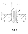
- Fig. 3 is a cross-sectional view showing mounting details of the pointing stick in the substrate.
- Fig. 4 is a perspective view of a keyboard with the pointing stick.
- Fig. 5 is a view of a computer system and the pointing stick mounted on a keyboard.
- pointing stick assembly 10 has a stick or shaft 11 and a first substrate 14 attached to shaft 11.
- the stick is preferably made out of ceramic.
- the first substrate 14 is preferably a flex cable, printed circuit board, polyamide sheet or ceramic.
- Shaft 11 and substrate 14 make up actuator 12.
- Shaft 11 extends through a substrate bore 19.
- Several strain gauge resistors 33, bridge 34 and conductors 36 are screen printed and cured, using conventional thick film resistor processing techniques, onto a side of shaft 11.
- Substrate 14 also has a top surface 20 and a bottom surface 15.
- Substrate 14 has disposed on bottom surface 15 electrically conductive circuit lines 17.
- a printed circuit board or second substrate 22 has several electrical contacts 23 and circuit lines 24 extending from the contacts 23.
- Contacts 23 are connected to the lines 17 by conventional electronic interconnection techniques such as using a solder joint 30.
- conductors 36 are connected to another end of circuit line 17 by another solder joint 30.
- Contacts 23 further connect with a signal processing or conditioning circuit device 27 on printed circuit board 22 via circuit lines 24.
- the signal processing device 27 is a conventional pointing stick electronic signal processing device. One such device is known as TrackPoint (tm) and is commercially available from Phillips Electronics Semiconductor Division.
- Several terminals 26 are provided to connect from printed circuit board 22 to an external electrical circuit such as a computer motherboard. Terminals 26 are connected to the circuit device 27 through contacts 23 and circuit lines 24.
- Printed circuit board 22 has a printed circuit board bore 25 extending therethrough.
- Shaft 11 may be fastened into the substrate bore 19 by gluing, press-fitting or swaging, for example.
- the shaft 11 may or may not extend into printed circuit board bore 25.
- Circuit bore 25 may be omitted if the shaft does not extend far enough.
- FIG. 2 shows a partial cross-sectional view of pointing stick assembly 10 mounted on a keyboard.
- Keyboard assembly 40 is a representation of a keyboard. Assembly 40 has a keyboard base 41, keys 42, and keyboard aperture 43.
- Pointing stick 10 is mounted to keyboard 40 with a mounting bracket 45.
- Shaft 11 extends through keyboard aperture 43 and between keys 42.
- Mounting bracket 45 is attached to keyboard base 41 by conventional fasteners such as rivet 44.
- the pointing stick assembly 10 is supported and contained by bracket 45 below the keyboard base 41.
- the shaft has an end 13 that may or may not extend beyond bottom surface 15.
- Figure 2 also shows details of the electrical connection between the substrate 14 and the printed circuit board 22.
- Solder 30 forms an electrical connection between pads 17 and contacts 23.
- Strain gages 31 are mounted on the sides of the stick 11 and are made of pressure sensitive resistors or strips 32, for electrically changing the resistance of the material in response to the amount of strain applied thereto, a conductive contact bridge 34 for electrically connecting the two resistors or strips 32, and conductors 36 for making electrical contact to circuit lines 17.
- the stick 11 extends through hole 19, and is held in place by an adhesive bond epoxy 40.
- an adhesive bond epoxy 40 For example, a cyanoacrylate adhesive material is also suitable.
- Conductors 36 are electrically connected to circuit lines 17 by solder joints 30.
- the pointing stick assembly 10 can be assembled as follows: The first step usually involves either the screening of resistive thick film or the sputtering of resistive thin film material and conductors 36 and bridge 34 on the sides of stick 11. The screened on material forms the strain gages 31. The second step often involves the placement of the stick 11 into the substrate 14 (or base). At this stage, a certain amount of bonding material 40 is applied onto the substrate 14 to secure the stick 11 to the substrate 14. Next, the solder 30 may be placed around the stick 11 to attach all eight conductors 36 to all eight circuit lines 17, two on each side of the stick 11. Finally, the whole assembly is cured to harden the bonding materials.
- Figure 4 shows a keyboard base 41 with the shaft 11 extending upwardly between keys 42.
- a rubber cap 48 is shown in phantom. The cap 48 may or may not be placed over shaft 11 to improve the ergonomics or feel for the user.
- Figure 5 shows a computer system and a keyboard assembly 40 with pointing stick assembly 10.
- Pointing stick 10 is located between keys 42.
- Keyboard 40 is electrically connected to computer 212 by cable 218.
- Computer 206 is electrically connected to monitor 213 by cable 206.
- Monitor 213 has a cursor 209 on the screen.
- Pointing stick assembly 10 allows a user to control the position of cursor 209 on monitor 213.
- Signal conditioning device 27 supplies a low level voltage through resistors 32.
- the change in resistance value is received by signal conditioning device 27 as an analog signal.
- the signal conditioning device changes the analog signal into a digital signal to be outputed on terminals 26 to another electrical circuit or mouse input (not shown).
- the assembly is completed by attaching the pointing stick to printed circuit board 22.
- Printed circuit board 22 may or may not have been previously populated with the electronic components necessary for signal conditioning. Solder, in paste form, is screened onto conductors 23 and substrate 14 is placed on top of printed circuit board 22 and is then run through a reflow furnace where the solder melts and connects lines 17 to conductors 23. Hot bar soldering could also be used to connect lines 17 to conductors 23.
- the assembly 10 is placed into bracket 45 and shaft 11 is inserted through keyboard base bore 43.
- Keyboard assembly 40 is completed by attaching bracket 45 to keyboard base 41 by fasteners 44.
- printed circuitry board 22 be another material such as a ceramic or a flexible film. Additionally, substrate 14 could be made from ceramic. Even though only one layer of circuit lines 24 are shown, it is possible to have a multi layer circuit board. It is further possible to have additional signal processing devices or circuitry 27 mounted on circuit board 22.
- Keyboard 40 is a representation of a keyboard and can be most any multilayered keyboard design.
- pointing stick assembly 10 disposed below keyboard base 41, with shaft 11 extending upwardly, it is considered equivalent to have pointing stick assembly 10 disposed on the top of the keyboard base 41 and positioned below the keys 42. Further, assembly 10 could be placed in a cutout region in base 41.
- the specification has shown the pointing stick assembly 10 mounted to a keyboard base 41, it is contemplated, however, to mount the pointing stick assembly to other types of bases or structures like remote control devices or joysticks.
- Another variation of the preferred embodiment is to use other types of fasteners to hold the control assembly 10 to the keyboard besides rivet 44 such as glue, press fitting, a retainer with holding tabs or a separate bracket.
- the shaft 11 may extend down into the printed circuit board hole 25 normally or may extend into the hole 25 during depression of the shaft 11.
- circuit lines 17 could be located on the top surface of the substrate 14 along with conductors 36 being above the substrate 14. Vias or plated thru holes could be used to electrically connect circuit lines 17 to the conductors 23.
- the shaft 11 has been shown having four sides with two strain gauge resistors on each. It is contemplated that other shaped shafts could be used such as hexagonal or octagonal with resistors disposed on one or more sides if it is desired to sense other axes of motion.
- shaft 11 could be integral to substrate 14 forming a unitary piece.
Abstract
Description
- This invention generally relates to a pointing device for controlling the positioning, movement and operation of an electronic device, for example, a cursor on a display screen. Specifically, there is a shaft, a substrate, resistor based strain gages, a printed circuit board and control electronics mounted on the printed circuit board.
- The following applications are herein incorporated by reference for supportive and related teachings:
- US-A-5894301 relates to a collar mounted pointing stick and has the same assignee as the present invention.
- EP-A-844584 relates to a pointing stick with z-axis actuation and has the same assignee as the present invention.
- EP-A-905600 relates to a unified bodied z-axis pointing stick and has the same assignee as the present invention.
- EP-A-862103 relates to a z-axis pointing stick with ESD protection and has the same assignee as the present invention.
- U.S. patent application identified by docket number CTS-1675 filed 5121197 relates to a pointing stick having an interposer connecting layer and has the same assignee as the present invention.
- Regarding the example of a pointing device for controlling a cursor, manufacturers of portable laptop computers, recognizing the need for placing the cursor controlling device in a permanent and more convenient location, installed a small stubby, button-like joystick centrally around the keys of the computer keyboard, specifically at the juncture of the "g," "h" and "b" keys of the standard "QWERTY" keyboard. The joystick, also known as a pointing stick, was sensitive to lateral pressure, the amount and direction of which were sensed and input into the computer to cause movement of the cursor, and the speed and direction of cursor movement corresponded to the amount and direction of pressure on the joystick. That manufacturer may also provide two upwardly extending "mouse" or "click" buttons immediately below the space bar. The joystick is connected by a flexible cable to a computer mother board where it connects to several electronic circuit devices that amplify and condition the signal coming form the joystick. The signal from the joystick is a low level analog signal. Electronic devices on the mother board amplify the low level analog signal and convert it to a digital signal.
- Despite the advantages of each type of prior art cursor control, none has been easily or economically manufactured. In particular, providing the electrical connections between the resistors and the circuitry on the computer mother board has been complicated and expensive. The flexible cable runs for a length along a keyboard before connecting with the motherboard.
- Further, the electrical signal coming from the joystick is a low level analog signal. As the signal travels along the flexible cable it loses some of its amplitude and is skewed due to attenuation of the signal. During travel along the cable, the signal can be corrupted due to coupling from external electromagnetic interference. These problems of routing a low level analog signal along a cable can cause erroneous readings as to the position of the pointing stick. Therefore, there is a current unmet and heretofore long felt need for a pointing stick, which is easily connected and has improved signal integrity.
- Examples of prior art representing the background to the present invention are as follows:
- US-Re. 35,016 discloses a three-axis force measurement stylus;
- US-A-5,489,900 discloses a strain sensitive columnar transducer for a data entry keyboard having a column upstanding from the keyboard;
- US-A-5,473,347 discloses a computer pointing device for controlling the positioning, movement and operation of a cursor on the display screen of a computer;
- US-A-5,407,285 discloses an apparatus for use in a computer keyboard for cursor control;
- US-A-5,521,596 discloses a sensor device placed either underneath a key cap or a key on a keyboard or between two keys on a keyboard so that cursor movement may be carried out from the keyboard itself;
- US-A-4,876,524 discloses an isometric control device or the like of the type having an elastic beam and strain gauges attached to the surface of the beam characterized by at least a first group of three strain gages each having an operative axis thereof inclined with a single predetermined angle with respect to the main axis of the beam, and the strain gauges disposed at a first predetermined level along the beam;
- US-A-4,680,577 discloses a multipurpose key switch for controlling cursor movement on a CRT display and for character entry includes a key cap that moves laterally to provide cursor control and that moves vertically for character entry; and
- US-A-5,659,334 discloses a force sensing pointing device.
-
- It is a feature of the invention to provide a pointing device for controlling the positioning, movement and operation of an electronic device, for example, a cursor on a display screen. Specifically, there is a shaft, a substrate, resistor based strain gages, a printed circuit board and control electronics mounted on the printed circuit board. The printed circuit board is mounted to a keyboard base.
- It is a feature of the invention to provide a device for generating conditioned electrical signals in response to forces applied to the device. The device includes an actuator having a first end, a second end and several strain sensitive resistors mounted on the second end of the actuator for generating an electrical signal representative of force applied to the shaft. A printed circuit board has the actuator mounted thereto. The printed circuit board has a signal conditioning means, mounted to the printed circuit board, for conditioning the electrical signal. The signal conditioning means operates to receive the electrical signal as an input and provides a conditioned signal as an output. An electrical connection means is disposed between the printed circuit board and the actuator, for electrically routing the electrical signal to the printed circuit board. A keyboard base has the printed circuit board and actuator mounted thereto.
- It is a further feature of the invention to provide the keyboard base with an aperture and the first end of the actuator extends through the keyboard aperture.
- It is a further feature of the invention to provide the conditioned signal on at least one terminal mounted on the printed circuit board.
- It is a further feature of the invention to receive the electrical signal in an analog state from the actuator and output the conditioned signal in a digital state.
- It is a further feature of the invention to place the strain sensitive resistors on a shaft of the actuator.
- There has thus been outlined, rather broadly, the more important features of the invention so that the detailed description thereof that follows may be better understood and so that the present contribution to the art may be better appreciated. There are, of course, additional features of the invention that will be described hereinafter and which will form the subject matter of the appended claims. Those skilled in the art will appreciate that the preferred embodiment may readily be used as a basis for the designing of other structures, methods and systems for carrying out the several purposes of the present invention. It is important, therefore, that the claims are regarded as including such equivalent constructions since they do not depart from the scope of the present invention.
- Fig. 1 is a perspective exploded view of the pointing stick with integral control circuitry.
- Fig. 2 is a cross-sectional view of the pointing stick of Figure 1 and control circuitry mounted on a keyboard using a mounting bracket.
- Fig. 3 is a cross-sectional view showing mounting details of the pointing stick in the substrate.
- Fig. 4 is a perspective view of a keyboard with the pointing stick.
- Fig. 5 is a view of a computer system and the pointing stick mounted on a keyboard.
- It is noted that the drawings of the invention are not to scale. The drawings are merely schematic representations, not intended to portray specific parameters of the invention. The drawings are intended to depict only typical embodiments of the invention and therefore should not be considered as limiting the scope of the invention. The invention will be described with additional specificity and detail through the accompanying drawings. The description of the invention may contain, for example, such descriptive terms as up, down, top, bottom, right or left. These terms are meant to provide a general orientation of the parts of the invention and are not meant to be limiting as to the scope of the invention.
- Referring to both Figures 1 and 2, there is a pointing stick with integral
control circuitry assembly 10 that can be used to control the movement of a cursor on a computer screen. In particular, pointingstick assembly 10 has a stick orshaft 11 and afirst substrate 14 attached toshaft 11. The stick is preferably made out of ceramic. Thefirst substrate 14 is preferably a flex cable, printed circuit board, polyamide sheet or ceramic.Shaft 11 andsubstrate 14 make upactuator 12.Shaft 11 extends through asubstrate bore 19. Several strain gauge resistors 33,bridge 34 andconductors 36 are screen printed and cured, using conventional thick film resistor processing techniques, onto a side ofshaft 11.Substrate 14 also has atop surface 20 and abottom surface 15.Substrate 14 has disposed onbottom surface 15 electrically conductive circuit lines 17. - A printed circuit board or
second substrate 22 has severalelectrical contacts 23 andcircuit lines 24 extending from thecontacts 23.Contacts 23 are connected to thelines 17 by conventional electronic interconnection techniques such as using asolder joint 30. Similarly,conductors 36 are connected to another end ofcircuit line 17 by another solder joint 30.Contacts 23 further connect with a signal processing or conditioning circuit device 27 on printedcircuit board 22 via circuit lines 24. The signal processing device 27 is a conventional pointing stick electronic signal processing device. One such device is known as TrackPoint (tm) and is commercially available from Phillips Electronics Semiconductor Division.Several terminals 26 are provided to connect from printedcircuit board 22 to an external electrical circuit such as a computer motherboard.Terminals 26 are connected to the circuit device 27 throughcontacts 23 and circuit lines 24. Printedcircuit board 22 has a printed circuit board bore 25 extending therethrough.Shaft 11 may be fastened into the substrate bore 19 by gluing, press-fitting or swaging, for example. Theshaft 11 may or may not extend into printed circuit board bore 25. Circuit bore 25 may be omitted if the shaft does not extend far enough. - Figure 2 shows a partial cross-sectional view of pointing
stick assembly 10 mounted on a keyboard.Keyboard assembly 40 is a representation of a keyboard.Assembly 40 has akeyboard base 41,keys 42, and keyboard aperture 43. Pointingstick 10 is mounted tokeyboard 40 with a mountingbracket 45.Shaft 11 extends through keyboard aperture 43 and betweenkeys 42. Mountingbracket 45 is attached tokeyboard base 41 by conventional fasteners such asrivet 44. Thepointing stick assembly 10 is supported and contained bybracket 45 below thekeyboard base 41. The shaft has an end 13 that may or may not extend beyondbottom surface 15. Figure 2 also shows details of the electrical connection between thesubstrate 14 and the printedcircuit board 22.Solder 30 forms an electrical connection betweenpads 17 andcontacts 23. - Referring to Fig. 3, there is a cross-sectional view taken through
substrate 14 showing mounting details ofshaft 11 tosubstrate 14. In particular, the following additional elements are illustrated: Strain gages 31 are mounted on the sides of thestick 11 and are made of pressure sensitive resistors or strips 32, for electrically changing the resistance of the material in response to the amount of strain applied thereto, aconductive contact bridge 34 for electrically connecting the two resistors or strips 32, andconductors 36 for making electrical contact to circuit lines 17. Thestick 11 extends throughhole 19, and is held in place by anadhesive bond epoxy 40. For example, a cyanoacrylate adhesive material is also suitable.Conductors 36 are electrically connected tocircuit lines 17 by solder joints 30. Thepointing stick assembly 10 can be assembled as follows: The first step usually involves either the screening of resistive thick film or the sputtering of resistive thin film material andconductors 36 andbridge 34 on the sides ofstick 11. The screened on material forms the strain gages 31. The second step often involves the placement of thestick 11 into the substrate 14 (or base). At this stage, a certain amount ofbonding material 40 is applied onto thesubstrate 14 to secure thestick 11 to thesubstrate 14. Next, thesolder 30 may be placed around thestick 11 to attach all eightconductors 36 to all eightcircuit lines 17, two on each side of thestick 11. Finally, the whole assembly is cured to harden the bonding materials. - Figure 4 shows a
keyboard base 41 with theshaft 11 extending upwardly betweenkeys 42. Arubber cap 48 is shown in phantom. Thecap 48 may or may not be placed overshaft 11 to improve the ergonomics or feel for the user. - Figure 5 shows a computer system and a
keyboard assembly 40 with pointingstick assembly 10. Pointingstick 10 is located betweenkeys 42.Keyboard 40 is electrically connected to computer 212 by cable 218.Computer 206 is electrically connected to monitor 213 bycable 206.Monitor 213 has acursor 209 on the screen. Pointingstick assembly 10 allows a user to control the position ofcursor 209 onmonitor 213. - When a user moves
shaft 11, forces exerted on the shaft are translated tosubstrate 14 and toresistors 32 causing the resistors to change their resistance value. Signal conditioning device 27 supplies a low level voltage throughresistors 32. The change in resistance value is received by signal conditioning device 27 as an analog signal. The signal conditioning device changes the analog signal into a digital signal to be outputed onterminals 26 to another electrical circuit or mouse input (not shown). - The assembly is completed by attaching the pointing stick to printed
circuit board 22. Printedcircuit board 22 may or may not have been previously populated with the electronic components necessary for signal conditioning. Solder, in paste form, is screened ontoconductors 23 andsubstrate 14 is placed on top of printedcircuit board 22 and is then run through a reflow furnace where the solder melts and connectslines 17 toconductors 23. Hot bar soldering could also be used to connectlines 17 toconductors 23. Theassembly 10 is placed intobracket 45 andshaft 11 is inserted through keyboard base bore 43.Keyboard assembly 40 is completed by attachingbracket 45 tokeyboard base 41 byfasteners 44. - One of ordinary skill in the art of making pointing sticks or other electronic controls such as remote controls, will realize that there are many different ways of accomplishing the preferred embodiment. For example, although
shaft 11 andsubstrate 14 were shown as separate pieces, they could be one piece. - It is further possible to have printed
circuitry board 22 be another material such as a ceramic or a flexible film. Additionally,substrate 14 could be made from ceramic. Even though only one layer ofcircuit lines 24 are shown, it is possible to have a multi layer circuit board. It is further possible to have additional signal processing devices or circuitry 27 mounted oncircuit board 22. -
Keyboard 40 is a representation of a keyboard and can be most any multilayered keyboard design. - Even though the specification has shown the
pointing stick assembly 10 disposed belowkeyboard base 41, withshaft 11 extending upwardly, it is considered equivalent to havepointing stick assembly 10 disposed on the top of thekeyboard base 41 and positioned below thekeys 42. Further,assembly 10 could be placed in a cutout region inbase 41. - The specification has shown the
pointing stick assembly 10 mounted to akeyboard base 41, it is contemplated, however, to mount the pointing stick assembly to other types of bases or structures like remote control devices or joysticks. - Another variation of the preferred embodiment is to use other types of fasteners to hold the
control assembly 10 to the keyboard besidesrivet 44 such as glue, press fitting, a retainer with holding tabs or a separate bracket. - The
shaft 11 may extend down into the printedcircuit board hole 25 normally or may extend into thehole 25 during depression of theshaft 11. - The circuit lines 17 could be located on the top surface of the
substrate 14 along withconductors 36 being above thesubstrate 14. Vias or plated thru holes could be used to electrically connectcircuit lines 17 to theconductors 23. - The
shaft 11 has been shown having four sides with two strain gauge resistors on each. It is contemplated that other shaped shafts could be used such as hexagonal or octagonal with resistors disposed on one or more sides if it is desired to sense other axes of motion. - Additionally,
shaft 11 could be integral tosubstrate 14 forming a unitary piece. - While the invention has been taught with specific reference to these embodiments, someone skilled in the art will recognize that changes can be made in form and detail without departing from the scope of the invention. The described embodiments are to be considered in all respects only as illustrative and not restrictive.
Claims (13)
- A device for generating electrical signals in response to forces applied thereto, comprising:a) an actuator having force sensing means outputting an electrical signal representative of a force applied thereto;b) a support mounting the actuator and carrying signal conditioning means for receiving the electrical signal from the force sensing means and for outputting a conditioned signal; andc) electrical connection means on the support between the force sensing means and the signal conducting means.
- A device according to Claim 1, wherein the signal conditioning means is arranged to receive an analogue signal from the force sensing means and to output a digital signal.
- A device according to Claim 1 or 2, wherein the force sensing means comprises at least one strain sensitive resistor mounted on the actuator for generating an electrical signal representative of force applied to the actuator, and wherein the actuator and the signal conditioning means are mounted on a printed circuit board.
- A device according to Claim 3, wherein the actuator has a plurality of strain sensitive resistors mounted thereon.
- A device according to any preceding claim, wherein the printed circuit board is held by a mounting bracket.
- A device according to any preceding claim, wherein the actuator has an attached shaft.
- A device according to Claim 6, wherein the mounting bracket is adapted to connect with a keyboard base which has an aperture and an end of the shaft extends through the keyboard aperture.
- A device according to Claim 6 or 7, wherein the actuator comprises a substrate, to which one end of the shaft is attached.
- A device according to any preceding claim, wherein the device outputs the conditioned signal on at least one terminal mounted on the support.
- A device according to Claim 3, 4 or 5, wherein the actuator has a shaft, having a first and second end, a substrate having the first end of the shaft attached thereto, at least one strain sensitive resistor mounted on the shaft for generating an electrical signal representative of a magnitude and direction of force applied to the shaft by a user, at least one circuit line disposed on the substrate and electrically connected to the resistor, and wherein, the electrical connection means are mounted between the substrate and the printed circuit board, for electrically routing the electrical signal from the circuit line through the electrical connection means and to the electrical conductor.
- A device according to Claim 10, wherein the substrate has a bore passing therethrough, the first end of the shaft being mounted in the substrate bore.
- A device according to Claim 10 or 11, wherein the electrical connection means is solder.
- An electronic control device for allowing a user to control the movement or operation of a responsive electronic system comprising:a) a base; andb) signal conditioning means, mounted to the base, for generating a digital electrical signal representative of a direction of mechanical forces applied thereon by a user.
Applications Claiming Priority (2)
| Application Number | Priority Date | Filing Date | Title |
|---|---|---|---|
| US14996698A | 1998-09-09 | 1998-09-09 | |
| US149966 | 1998-09-09 |
Publications (2)
| Publication Number | Publication Date |
|---|---|
| EP0986022A2 true EP0986022A2 (en) | 2000-03-15 |
| EP0986022A3 EP0986022A3 (en) | 2000-06-28 |
Family
ID=22532558
Family Applications (1)
| Application Number | Title | Priority Date | Filing Date |
|---|---|---|---|
| EP99306778A Withdrawn EP0986022A3 (en) | 1998-09-09 | 1999-08-26 | A pointing stick having integral control circuitry |
Country Status (3)
| Country | Link |
|---|---|
| EP (1) | EP0986022A3 (en) |
| JP (1) | JP2000099262A (en) |
| TW (1) | TW476906B (en) |
Cited By (3)
| Publication number | Priority date | Publication date | Assignee | Title |
|---|---|---|---|---|
| WO2005001866A1 (en) * | 2003-06-26 | 2005-01-06 | Sony Ericsson Mobile Communications Ab | Switch dome device |
| WO2013153048A1 (en) * | 2012-04-11 | 2013-10-17 | Behr-Hella Thermocontrol Gmbh | Operating unit for a vehicle component |
| CN105843418A (en) * | 2015-02-04 | 2016-08-10 | 联想(新加坡)私人有限公司 | Pointing device, keyboard assembly, and portable computer |
Families Citing this family (1)
| Publication number | Priority date | Publication date | Assignee | Title |
|---|---|---|---|---|
| JP5719659B2 (en) * | 2011-03-30 | 2015-05-20 | ミネベア株式会社 | Pointing stick mounting structure |
Citations (6)
| Publication number | Priority date | Publication date | Assignee | Title |
|---|---|---|---|---|
| US5349370A (en) * | 1991-10-09 | 1994-09-20 | Mitsumi Electric Co., Ltd. | Signal processing circuit for a pointing device |
| EP0616298A1 (en) * | 1993-02-25 | 1994-09-21 | Matsushita Electric Industrial Co., Ltd. | Position input device and input apparatus using the same |
| US5579033A (en) * | 1992-05-20 | 1996-11-26 | International Business Machines Corporation | Pointing device for retrofitting onto the keyboard of an existing computer system |
| US5754167A (en) * | 1994-03-02 | 1998-05-19 | Alps Electric Co., Ltd. | Coordinate inputting device for a computer keyboard |
| EP0862103A2 (en) * | 1997-02-04 | 1998-09-02 | CTS Corporation | Pointing device |
| EP0905600A1 (en) * | 1997-09-26 | 1999-03-31 | CTS Corporation | Pointing stick |
-
1999
- 1999-08-19 TW TW88114159A patent/TW476906B/en active
- 1999-08-19 JP JP11232816A patent/JP2000099262A/en active Pending
- 1999-08-26 EP EP99306778A patent/EP0986022A3/en not_active Withdrawn
Patent Citations (6)
| Publication number | Priority date | Publication date | Assignee | Title |
|---|---|---|---|---|
| US5349370A (en) * | 1991-10-09 | 1994-09-20 | Mitsumi Electric Co., Ltd. | Signal processing circuit for a pointing device |
| US5579033A (en) * | 1992-05-20 | 1996-11-26 | International Business Machines Corporation | Pointing device for retrofitting onto the keyboard of an existing computer system |
| EP0616298A1 (en) * | 1993-02-25 | 1994-09-21 | Matsushita Electric Industrial Co., Ltd. | Position input device and input apparatus using the same |
| US5754167A (en) * | 1994-03-02 | 1998-05-19 | Alps Electric Co., Ltd. | Coordinate inputting device for a computer keyboard |
| EP0862103A2 (en) * | 1997-02-04 | 1998-09-02 | CTS Corporation | Pointing device |
| EP0905600A1 (en) * | 1997-09-26 | 1999-03-31 | CTS Corporation | Pointing stick |
Cited By (5)
| Publication number | Priority date | Publication date | Assignee | Title |
|---|---|---|---|---|
| WO2005001866A1 (en) * | 2003-06-26 | 2005-01-06 | Sony Ericsson Mobile Communications Ab | Switch dome device |
| US7663068B2 (en) | 2003-06-26 | 2010-02-16 | Sony Ericsson Mobile Communications Ab | Switch dome device |
| WO2013153048A1 (en) * | 2012-04-11 | 2013-10-17 | Behr-Hella Thermocontrol Gmbh | Operating unit for a vehicle component |
| CN105843418A (en) * | 2015-02-04 | 2016-08-10 | 联想(新加坡)私人有限公司 | Pointing device, keyboard assembly, and portable computer |
| CN105843418B (en) * | 2015-02-04 | 2019-01-11 | 联想(新加坡)私人有限公司 | Indicator, keyboard components and portable computer |
Also Published As
| Publication number | Publication date |
|---|---|
| TW476906B (en) | 2002-02-21 |
| JP2000099262A (en) | 2000-04-07 |
| EP0986022A3 (en) | 2000-06-28 |
Similar Documents
| Publication | Publication Date | Title |
|---|---|---|
| US6359613B1 (en) | Pointing stick having chip resistors | |
| US6002388A (en) | Pointing stick having a flexible interposer | |
| US6331849B1 (en) | Integrated surface-mount pointing device | |
| US6239786B1 (en) | Pointing stick with top mounted z-axis sensor | |
| US5966117A (en) | Z-axis sensing pointing stick with base as strain concentrator | |
| US6304247B1 (en) | Piezoelectric stick pointing device | |
| US6323840B1 (en) | Surface-mount pointing device | |
| US5872320A (en) | Force transducer with co-planar strain gauges | |
| US6121954A (en) | Unified bodied z-axis sensing pointing stick | |
| US6195082B1 (en) | Low noise circuit board for trackpoint pointing device | |
| US6753850B2 (en) | Low profile cursor control device | |
| US6788291B2 (en) | Integrated surface-mount pointing device | |
| JPH11238431A (en) | Integral type keyboard and operation control device | |
| EP1581924A2 (en) | Miniature highly manufacturable mouse pointing device | |
| US6137475A (en) | Pointing stick having an interposer connecting layer | |
| US20030218598A1 (en) | Keyboard track stick | |
| JP4141575B2 (en) | Pointing device | |
| EP0986022A2 (en) | A pointing stick having integral control circuitry | |
| JP4141574B2 (en) | Thick film circuit board for pointing stick | |
| US6504703B1 (en) | Capacitive transducer apparatus and method of manufacture thereof for computer display user interface | |
| JPH11259229A (en) | Z-axial pointing stick equipped with esd protection | |
| US7170487B2 (en) | Pointing device and method of producing the same | |
| MXPA98000988A (en) | Vertical point axle lever with electrostat dump protection | |
| JP2000259341A (en) | Pointing stick |
Legal Events
| Date | Code | Title | Description |
|---|---|---|---|
| PUAI | Public reference made under article 153(3) epc to a published international application that has entered the european phase |
Free format text: ORIGINAL CODE: 0009012 |
|
| AK | Designated contracting states |
Kind code of ref document: A2 Designated state(s): DE FR GB |
|
| AX | Request for extension of the european patent |
Free format text: AL;LT;LV;MK;RO;SI |
|
| PUAL | Search report despatched |
Free format text: ORIGINAL CODE: 0009013 |
|
| AK | Designated contracting states |
Kind code of ref document: A3 Designated state(s): AT BE CH CY DE DK ES FI FR GB GR IE IT LI LU MC NL PT SE |
|
| AX | Request for extension of the european patent |
Free format text: AL;LT;LV;MK;RO;SI |
|
| RIC1 | Information provided on ipc code assigned before grant |
Free format text: 7G 06K 11/18 A, 7G 05G 9/047 B, 7G 06F 3/02 B |
|
| 17P | Request for examination filed |
Effective date: 20001120 |
|
| AKX | Designation fees paid |
Free format text: DE FR GB |
|
| STAA | Information on the status of an ep patent application or granted ep patent |
Free format text: STATUS: THE APPLICATION HAS BEEN WITHDRAWN |
|
| 18W | Application withdrawn |
Withdrawal date: 20020222 |